US5971613A - Bag constructions having inwardly directed side seal portions - Google Patents
Bag constructions having inwardly directed side seal portionsDownload PDFInfo
- Publication number
- US5971613A US5971613AUS08/843,156US84315697AUS5971613AUS 5971613 AUS5971613 AUS 5971613AUS 84315697 AUS84315697 AUS 84315697AUS 5971613 AUS5971613 AUS 5971613A
- Authority
- US
- United States
- Prior art keywords
- inner edge
- panel sections
- inwardly directed
- section
- edge
- Prior art date
- Legal status (The legal status is an assumption and is not a legal conclusion. Google has not performed a legal analysis and makes no representation as to the accuracy of the status listed.)
- Expired - Lifetime
Links
Images


Classifications
- B—PERFORMING OPERATIONS; TRANSPORTING
- B29—WORKING OF PLASTICS; WORKING OF SUBSTANCES IN A PLASTIC STATE IN GENERAL
- B29C—SHAPING OR JOINING OF PLASTICS; SHAPING OF MATERIAL IN A PLASTIC STATE, NOT OTHERWISE PROVIDED FOR; AFTER-TREATMENT OF THE SHAPED PRODUCTS, e.g. REPAIRING
- B29C66/00—General aspects of processes or apparatus for joining preformed parts
- B29C66/01—General aspects dealing with the joint area or with the area to be joined
- B29C66/05—Particular design of joint configurations
- B29C66/10—Particular design of joint configurations particular design of the joint cross-sections
- B29C66/11—Joint cross-sections comprising a single joint-segment, i.e. one of the parts to be joined comprising a single joint-segment in the joint cross-section
- B29C66/112—Single lapped joints
- B29C66/1122—Single lap to lap joints, i.e. overlap joints
- B—PERFORMING OPERATIONS; TRANSPORTING
- B29—WORKING OF PLASTICS; WORKING OF SUBSTANCES IN A PLASTIC STATE IN GENERAL
- B29C—SHAPING OR JOINING OF PLASTICS; SHAPING OF MATERIAL IN A PLASTIC STATE, NOT OTHERWISE PROVIDED FOR; AFTER-TREATMENT OF THE SHAPED PRODUCTS, e.g. REPAIRING
- B29C65/00—Joining or sealing of preformed parts, e.g. welding of plastics materials; Apparatus therefor
- B29C65/02—Joining or sealing of preformed parts, e.g. welding of plastics materials; Apparatus therefor by heating, with or without pressure
- B29C65/18—Joining or sealing of preformed parts, e.g. welding of plastics materials; Apparatus therefor by heating, with or without pressure using heated tools
- B—PERFORMING OPERATIONS; TRANSPORTING
- B29—WORKING OF PLASTICS; WORKING OF SUBSTANCES IN A PLASTIC STATE IN GENERAL
- B29C—SHAPING OR JOINING OF PLASTICS; SHAPING OF MATERIAL IN A PLASTIC STATE, NOT OTHERWISE PROVIDED FOR; AFTER-TREATMENT OF THE SHAPED PRODUCTS, e.g. REPAIRING
- B29C66/00—General aspects of processes or apparatus for joining preformed parts
- B29C66/01—General aspects dealing with the joint area or with the area to be joined
- B29C66/05—Particular design of joint configurations
- B29C66/20—Particular design of joint configurations particular design of the joint lines, e.g. of the weld lines
- B29C66/22—Particular design of joint configurations particular design of the joint lines, e.g. of the weld lines said joint lines being in the form of recurring patterns
- B29C66/221—Particular design of joint configurations particular design of the joint lines, e.g. of the weld lines said joint lines being in the form of recurring patterns being in the form of a sinusoidal wave
- B—PERFORMING OPERATIONS; TRANSPORTING
- B29—WORKING OF PLASTICS; WORKING OF SUBSTANCES IN A PLASTIC STATE IN GENERAL
- B29C—SHAPING OR JOINING OF PLASTICS; SHAPING OF MATERIAL IN A PLASTIC STATE, NOT OTHERWISE PROVIDED FOR; AFTER-TREATMENT OF THE SHAPED PRODUCTS, e.g. REPAIRING
- B29C66/00—General aspects of processes or apparatus for joining preformed parts
- B29C66/01—General aspects dealing with the joint area or with the area to be joined
- B29C66/05—Particular design of joint configurations
- B29C66/20—Particular design of joint configurations particular design of the joint lines, e.g. of the weld lines
- B29C66/22—Particular design of joint configurations particular design of the joint lines, e.g. of the weld lines said joint lines being in the form of recurring patterns
- B29C66/229—Other specific patterns not provided for in B29C66/221 - B29C66/227
- B—PERFORMING OPERATIONS; TRANSPORTING
- B29—WORKING OF PLASTICS; WORKING OF SUBSTANCES IN A PLASTIC STATE IN GENERAL
- B29C—SHAPING OR JOINING OF PLASTICS; SHAPING OF MATERIAL IN A PLASTIC STATE, NOT OTHERWISE PROVIDED FOR; AFTER-TREATMENT OF THE SHAPED PRODUCTS, e.g. REPAIRING
- B29C66/00—General aspects of processes or apparatus for joining preformed parts
- B29C66/50—General aspects of joining tubular articles; General aspects of joining long products, i.e. bars or profiled elements; General aspects of joining single elements to tubular articles, hollow articles or bars; General aspects of joining several hollow-preforms to form hollow or tubular articles
- B29C66/51—Joining tubular articles, profiled elements or bars; Joining single elements to tubular articles, hollow articles or bars; Joining several hollow-preforms to form hollow or tubular articles
- B29C66/53—Joining single elements to tubular articles, hollow articles or bars
- B29C66/532—Joining single elements to the wall of tubular articles, hollow articles or bars
- B29C66/5326—Joining single elements to the wall of tubular articles, hollow articles or bars said single elements being substantially flat
- B29C66/53261—Enclosing tubular articles between substantially flat elements
- B29C66/53262—Enclosing spouts between the walls of bags, e.g. of medical bags
- B29C66/53263—Enclosing spouts between the walls of bags, e.g. of medical bags said spouts comprising wings, e.g. said spouts being of ship-like or canoe-like form to avoid leaks in the corners
- B—PERFORMING OPERATIONS; TRANSPORTING
- B29—WORKING OF PLASTICS; WORKING OF SUBSTANCES IN A PLASTIC STATE IN GENERAL
- B29C—SHAPING OR JOINING OF PLASTICS; SHAPING OF MATERIAL IN A PLASTIC STATE, NOT OTHERWISE PROVIDED FOR; AFTER-TREATMENT OF THE SHAPED PRODUCTS, e.g. REPAIRING
- B29C66/00—General aspects of processes or apparatus for joining preformed parts
- B29C66/80—General aspects of machine operations or constructions and parts thereof
- B—PERFORMING OPERATIONS; TRANSPORTING
- B65—CONVEYING; PACKING; STORING; HANDLING THIN OR FILAMENTARY MATERIAL
- B65D—CONTAINERS FOR STORAGE OR TRANSPORT OF ARTICLES OR MATERIALS, e.g. BAGS, BARRELS, BOTTLES, BOXES, CANS, CARTONS, CRATES, DRUMS, JARS, TANKS, HOPPERS, FORWARDING CONTAINERS; ACCESSORIES, CLOSURES, OR FITTINGS THEREFOR; PACKAGING ELEMENTS; PACKAGES
- B65D75/00—Packages comprising articles or materials partially or wholly enclosed in strips, sheets, blanks, tubes or webs of flexible sheet material, e.g. in folded wrappers
- B65D75/008—Standing pouches, i.e. "Standbeutel"
- B—PERFORMING OPERATIONS; TRANSPORTING
- B29—WORKING OF PLASTICS; WORKING OF SUBSTANCES IN A PLASTIC STATE IN GENERAL
- B29C—SHAPING OR JOINING OF PLASTICS; SHAPING OF MATERIAL IN A PLASTIC STATE, NOT OTHERWISE PROVIDED FOR; AFTER-TREATMENT OF THE SHAPED PRODUCTS, e.g. REPAIRING
- B29C66/00—General aspects of processes or apparatus for joining preformed parts
- B29C66/01—General aspects dealing with the joint area or with the area to be joined
- B29C66/02—Preparation of the material, in the area to be joined, prior to joining or welding
- B29C66/024—Thermal pre-treatments
- B29C66/0242—Heating, or preheating, e.g. drying
- B—PERFORMING OPERATIONS; TRANSPORTING
- B29—WORKING OF PLASTICS; WORKING OF SUBSTANCES IN A PLASTIC STATE IN GENERAL
- B29C—SHAPING OR JOINING OF PLASTICS; SHAPING OF MATERIAL IN A PLASTIC STATE, NOT OTHERWISE PROVIDED FOR; AFTER-TREATMENT OF THE SHAPED PRODUCTS, e.g. REPAIRING
- B29C66/00—General aspects of processes or apparatus for joining preformed parts
- B29C66/70—General aspects of processes or apparatus for joining preformed parts characterised by the composition, physical properties or the structure of the material of the parts to be joined; Joining with non-plastics material
- B29C66/71—General aspects of processes or apparatus for joining preformed parts characterised by the composition, physical properties or the structure of the material of the parts to be joined; Joining with non-plastics material characterised by the composition of the plastics material of the parts to be joined
- B—PERFORMING OPERATIONS; TRANSPORTING
- B29—WORKING OF PLASTICS; WORKING OF SUBSTANCES IN A PLASTIC STATE IN GENERAL
- B29C—SHAPING OR JOINING OF PLASTICS; SHAPING OF MATERIAL IN A PLASTIC STATE, NOT OTHERWISE PROVIDED FOR; AFTER-TREATMENT OF THE SHAPED PRODUCTS, e.g. REPAIRING
- B29C66/00—General aspects of processes or apparatus for joining preformed parts
- B29C66/70—General aspects of processes or apparatus for joining preformed parts characterised by the composition, physical properties or the structure of the material of the parts to be joined; Joining with non-plastics material
- B29C66/72—General aspects of processes or apparatus for joining preformed parts characterised by the composition, physical properties or the structure of the material of the parts to be joined; Joining with non-plastics material characterised by the structure of the material of the parts to be joined
- B29C66/723—General aspects of processes or apparatus for joining preformed parts characterised by the composition, physical properties or the structure of the material of the parts to be joined; Joining with non-plastics material characterised by the structure of the material of the parts to be joined being multi-layered
- B29C66/7232—General aspects of processes or apparatus for joining preformed parts characterised by the composition, physical properties or the structure of the material of the parts to be joined; Joining with non-plastics material characterised by the structure of the material of the parts to be joined being multi-layered comprising a non-plastics layer
- B29C66/72321—General aspects of processes or apparatus for joining preformed parts characterised by the composition, physical properties or the structure of the material of the parts to be joined; Joining with non-plastics material characterised by the structure of the material of the parts to be joined being multi-layered comprising a non-plastics layer consisting of metals or their alloys
- B—PERFORMING OPERATIONS; TRANSPORTING
- B29—WORKING OF PLASTICS; WORKING OF SUBSTANCES IN A PLASTIC STATE IN GENERAL
- B29C—SHAPING OR JOINING OF PLASTICS; SHAPING OF MATERIAL IN A PLASTIC STATE, NOT OTHERWISE PROVIDED FOR; AFTER-TREATMENT OF THE SHAPED PRODUCTS, e.g. REPAIRING
- B29C66/00—General aspects of processes or apparatus for joining preformed parts
- B29C66/70—General aspects of processes or apparatus for joining preformed parts characterised by the composition, physical properties or the structure of the material of the parts to be joined; Joining with non-plastics material
- B29C66/72—General aspects of processes or apparatus for joining preformed parts characterised by the composition, physical properties or the structure of the material of the parts to be joined; Joining with non-plastics material characterised by the structure of the material of the parts to be joined
- B29C66/723—General aspects of processes or apparatus for joining preformed parts characterised by the composition, physical properties or the structure of the material of the parts to be joined; Joining with non-plastics material characterised by the structure of the material of the parts to be joined being multi-layered
- B29C66/7234—General aspects of processes or apparatus for joining preformed parts characterised by the composition, physical properties or the structure of the material of the parts to be joined; Joining with non-plastics material characterised by the structure of the material of the parts to be joined being multi-layered comprising a barrier layer
- B—PERFORMING OPERATIONS; TRANSPORTING
- B29—WORKING OF PLASTICS; WORKING OF SUBSTANCES IN A PLASTIC STATE IN GENERAL
- B29C—SHAPING OR JOINING OF PLASTICS; SHAPING OF MATERIAL IN A PLASTIC STATE, NOT OTHERWISE PROVIDED FOR; AFTER-TREATMENT OF THE SHAPED PRODUCTS, e.g. REPAIRING
- B29C66/00—General aspects of processes or apparatus for joining preformed parts
- B29C66/80—General aspects of machine operations or constructions and parts thereof
- B29C66/83—General aspects of machine operations or constructions and parts thereof characterised by the movement of the joining or pressing tools
- B29C66/832—Reciprocating joining or pressing tools
- B29C66/8322—Joining or pressing tools reciprocating along one axis
- B—PERFORMING OPERATIONS; TRANSPORTING
- B29—WORKING OF PLASTICS; WORKING OF SUBSTANCES IN A PLASTIC STATE IN GENERAL
- B29C—SHAPING OR JOINING OF PLASTICS; SHAPING OF MATERIAL IN A PLASTIC STATE, NOT OTHERWISE PROVIDED FOR; AFTER-TREATMENT OF THE SHAPED PRODUCTS, e.g. REPAIRING
- B29C66/00—General aspects of processes or apparatus for joining preformed parts
- B29C66/80—General aspects of machine operations or constructions and parts thereof
- B29C66/84—Specific machine types or machines suitable for specific applications
- B29C66/851—Bag or container making machines
- B29C66/8511—Bag making machines
- Y—GENERAL TAGGING OF NEW TECHNOLOGICAL DEVELOPMENTS; GENERAL TAGGING OF CROSS-SECTIONAL TECHNOLOGIES SPANNING OVER SEVERAL SECTIONS OF THE IPC; TECHNICAL SUBJECTS COVERED BY FORMER USPC CROSS-REFERENCE ART COLLECTIONS [XRACs] AND DIGESTS
- Y10—TECHNICAL SUBJECTS COVERED BY FORMER USPC
- Y10S—TECHNICAL SUBJECTS COVERED BY FORMER USPC CROSS-REFERENCE ART COLLECTIONS [XRACs] AND DIGESTS
- Y10S383/00—Flexible bags
- Y10S383/903—Stress relief
- Y—GENERAL TAGGING OF NEW TECHNOLOGICAL DEVELOPMENTS; GENERAL TAGGING OF CROSS-SECTIONAL TECHNOLOGIES SPANNING OVER SEVERAL SECTIONS OF THE IPC; TECHNICAL SUBJECTS COVERED BY FORMER USPC CROSS-REFERENCE ART COLLECTIONS [XRACs] AND DIGESTS
- Y10—TECHNICAL SUBJECTS COVERED BY FORMER USPC
- Y10S—TECHNICAL SUBJECTS COVERED BY FORMER USPC CROSS-REFERENCE ART COLLECTIONS [XRACs] AND DIGESTS
- Y10S383/00—Flexible bags
- Y10S383/906—Dispensing feature
Definitions
- the present inventionrelates to bag or pouch constructions.
- the inventionconcerns an arrangement in which a bag or pouch construction includes a side seal with a nonlinear edge.
- the inventionalso concerns methods for preparing and using such arrangements.
- a variety of itemsare marketed and enclosed within flexible bags or bag constructions. Examples of such products include shampoo, soap, detergent, lotion, and others. Further, many other products such as nuts, candies, coffee, salt, seed, fertilizer, and the like are also packaged in flexible bags, with or without pour nozzles.
- the bagsmay include a reclosable zipper arrangement at one end.
- Flexible bagssometimes have a base, such as a bottom gusset or pad, and are arranged to stand upright when filled. This permits the seller to display the bag in a visible and attractive manner. Improvements for maximizing the attractiveness of a flexible bag have been desirable.
- a bag construction or arrangementincludes first and second opposed panel sections.
- First and second side sealsare between the panel sections, and define a bag construction interior.
- the first and second side sealseach have an inner edge portion adjacent to the bag construction interior.
- the first side seal inner edge portionhas at least one nonlinear edge section extending over a part of the first side seal inner edge portion.
- the non-linear edge sectionextends a distance of at least about 10 cm over the part. In many instances, the non-linear edge section may extend a distance of about 10-61 cm over the part, and in some instances more.
- the non-linear edge sectionincludes a plurality of spaced inwardly directed projections.
- the plurality of spaced inwardly directed projectionspreferably extend a distance of at least 30% of a length the first side edge. Indeed, the plurality of spaced inwardly directed projections may extend over a distance of about 30-100% of a length of the first side edge.
- the non-linear edge sectionincludes at least 4 and preferably at least 13 spaced inwardly directed projections.
- each of the projectionsmay be uniform, or of identical size and shape, to one another.
- Some arrangementsmay include the non-linear edge section having a plurality of inwardly directed projections alternating with a plurality of outwardly directed recesses.
- the non-linear edge sectionis undulated.
- the non-linear edge sectionmay be defined by a geometry similar to that of a curve having a height of about 0.5-4 mm.
- the non-linear edge sectionmay extend a complete length of the first inner edge portion, in some arrangements.
- the second side seal inner edge portionhas at least one non-linear edge section extending over a portion thereof.
- the non-linear edge section of the second side seal inner edge portionmay also include a plurality of spaced inwardly directed projections.
- a base gusset memberis oriented in extension between the first and second panel sections.
- the base gusset membermay include distribution apertures therein.
- the base gusset membercan be a separate section joined to the first and second panel sections; alternatively, the base gusset member can be part of the same section of material as the first and second panel sections.
- first and second panel sectionsare separate pieces of material joined along the opposite side edges.
- first and second panel sectionsmay be part of the same piece of material, for example, if made by a form-fill-seal process.
- a fitmentis secured to the first and second panel sections.
- Certain embodimentscan include a transverse openable and reclosable closure arrangement extending between the first and second panel sections.
- This closure arrangementmay include a rib and trough closure arrangement.
- the methodincludes a step of providing first and second continuous webs of panel section material. This may include two discrete rolls of panel section material, or it may be from a single roll and then split into two webs.
- the first and second websare oriented with respect to one another to form a continuous feed of pouch blank with front and back faces and first and second opposite side edges.
- the continuous feed of pouch blankis heat sealed by forming a non-linear seal transverse to the first and second side edges to join the front and back faces, and forming a pouch arrangement joined to an adjacent pouch arrangement at the non-linear seal.
- the pouch blankis then separated into individual ones of pouch arrangements by cutting along the non-linear seal.
- the step of forming a non-linear sealincludes forming a seal having a pair of opposite seal edges.
- Each of the seal edgeshas a plurality of spaced projections. This separates the pouch blank into individual pouch arrangements, where each pouch arrangement includes a side seal with a plurality of spaced projections adjacent to, or in communication with, the pouch interior.
- the methodincludes orienting a continuous base gusset between the first and second webs.
- the inventionin another aspect, concerns a seal bar arrangement.
- the seal bar arrangementincludes a rigid bar having a work-engaging surface.
- the baris constructed and arranged to conduct and transmit heat through the work-engaging surface.
- the work-engaging surfaceincludes a flat portion extending at least a partial length of the bar, and first and second side portions intersecting the flat portion.
- Each of the first and second side portionshave an undulated segment and extend at least a partial length of the bar.
- the undulated segment of the first and second side portionsincludes curved projections, each having a height of about 0.5-4 mm and a length of about 12-20 mm.
- the first and second side portionsmay extend a complete length of the bar. In a typical embodiment, the height is about 2.4 mm, and the length is about 16 mm.
- FIG. 1is a perspective view of a first embodiment of a bag arrangement at least partially filled, according to the present invention
- FIG. 2is a plan view of the bag arrangement shown in FIG. 1, devoid of any contents and in a collapsed orientation;
- FIG. 3is a plan view of a second embodiment of a bag arrangement according to the present invention.
- FIG. 4is a plan view of a third embodiment of a bag arrangement according to the present invention.
- FIG. 5is an enlarged, fragmented view of a side edge of the embodiments of FIGS. 1-4 showing one seal, according to the present invention
- FIG. 6is a view similar to FIG. 5, illustrating an alternate embodiment, according to the present invention.
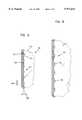
- FIG. 7is a view similar to FIG. 5, illustrating another alternative embodiment, according to the present invention.
- FIG. 8is a top plan view of one embodiment of a seal bar, according to the present invention.
- FIG. 9is an end view of the seal bar shown in FIG. 8, according to the present invention.
- FIG. 10is a schematic representation of certain of the steps for conducting a method according to the present invention.
- the present inventionimproves certain prior art bag arrangements by providing a side seal with a non-linear edge.
- the sealmay include an edge with a series, or plurality, of spaced inwardly directed projections.
- the improved sealimproves the attractiveness of bags or pouches by aiding them to stand upright in a straight configuration when at least partially filled with material.
- One of the problems associated with prior art bag arrangementsis that after the bags are at least partially or completely filled and oriented to stand in an upright manner, the side edges of the bag have a tendency to buckle. That is, at least a portion of the upper part of the bag may fold down upon sections lower than it.
- the present inventionuses, in one typical arrangement, side seals with a series of spaced inwardly directed projections, which help the bag, when filled or partially filled with material, to stand upright with a lower propensity for buckling at the sides. While no particular theory with respect to this observation is asserted herein, it may be that the non-linear seals according to the present invention provide shock absorbers for the filled bag. It is noted that a complete absence of any buckling is not a requirement of arrangements described herein.
- FIG. 1One example of a bag construction made according to the present invention is illustrated in FIG. 1 generally at 20.
- the bag construction 20 depicted in FIG. 1is illustrated as it would generally appear filled or at least partially filled with material 22 for storage therein.
- material 22may include flowable materials such as liquids, for example, soap, shampoo, lotion; alternatively, such material may include flowable particulates such as coffee beans and grounds, grass seed, fertilizer, candies, salt grains and pellets, and the like.
- bag construction 20includes first and second opposed side walls, panel sections, or panels 24 and 26.
- first and second panel sections 24, 26are separate pieces and then joined together.
- first and second panel sections 24, 26may be formed from a single, continuous web material and folded into opposed panel sections. This latter type of arrangement could be constructed in a form-fill-seal machine.
- Bag construction 20is illustrated as being generally rectangular with a slanted portion 25, although other shapes may be utilized.
- Each of the first and second panel sections 24, 26includes a first end edge 28 at a first end 30 of the bag construction 20 and a second end edge 32 at a second end 34 of the bag construction 20. Extending between the first and second end edges 28, 32 are opposite side edges 35, 38. In a typical orientation, the bag construction first end 30 corresponds to a top portion, and second end 34 corresponds to a bottom portion. Slanted portion 25 extends between first end edge 28 and side edge 36, at an angle relative to the remainder of side edge 36.
- a fitment, spout or pour nozzle 27is secured between the first and second panel sections 24, 26 along the slanted portion 25. Pour nozzle 27 may include a cap 31. In the arrangement shown, cap 31 is threadably secured to the nozzle 27.
- each of first and second panel sections 24, 26includes a second end edge 32 which corresponds to the second end 34 of the overall construction 20.
- a base gusset or bottom gusset 39(FIG. 2) is positioned.
- Gusset 39is secured to each of the first and second panel sections 24, 26 by use of appropriate sealing such as heat sealing.
- gusset 39is a separate piece of web material attached to the first and second panel sections 24, 26.
- the gusset 39may be formed from a single, continuous web material as the first and second panel sections 24, 26 and folded into a gusset position with respect to the opposed panel sections. As illustrated in FIG.
- the bottom gusset 39expands to form a base and to support the construction in a standing or upright position projecting upwardly from the base.
- the contents of bag construction 20may be dispensed, as selected, through nozzle 27.
- the gusset 39defines semi-circular portions 90, 91 (FIG. 2) along the first and second edges 36, 38, respectively, adjacent to the second end 34.
- Semi-circular portions 90, 91are sections of gusset material removed; i.e. cuts in the gusset 39. This permits the first and second panel sections 24, 26 to be heat sealed directly to one another in this location, during the manufacturing process.
- the gusset 39is sealed to the panel sections, and the panel sections are not sealed to one another because the gusset is positioned between them.
- First and second panel sections 24, 26are secured to one another along portions of side edges 36, 38. Preferably, this is by use of seals 40, 42.
- seals 40, 42extend along side edges 36, 38, respectively, between first end 30 and points 44, 46 where the gusset 39 intersects the side edges 36, 38. Further, at the region of semi-circular portions 90, 91, the first and second panel sections 24, 26 are sealed to one another.
- first and second seals 40, 42have an inner edge portion 48, 50, respectively, adjacent to, or in communication with, the bag construction interior 52.
- Each of the first and second seals 40, 42also include an opposite outer edge portion 54, 56, respectively.
- the first and second seals 40, 42include a non-linear configuration 58 along the inner edge portions 48, 50.
- the term "non-linear configuration" and variants thereofmeans an edge which is not linear, or straight, along the entire surface of the edge 48, 50, for example from the first end 30 down to points 44, 46 where the seals 40, 42 intersect the ends 44, 46, respectively, of the gusset region.
- a "non-linear configuration"may include at least some portions along the inner edges 48, 50 which are linear, or straight.
- at least some portions along the side seals of the bag constructionmay be curved or include other geometrical shapes (with or without some straight portions), but the edge is not straight along the entire continuous inner edge surface 48, 50 of the seal. It has been found that when the first and second inner edges 48, 50 are constructed with non-linear edges 58, certain advantages result.
- a bag or pouch construction including one or more side seals with at least partial sections having non-linear edges as describedcan exhibit less tendency to buckle at the sides along the seals when filled or partially filled with material and oriented in an upright position.
- One typical, useable, non-linear edge configurationincludes an edge with a series, or plurality, of spaced inwardly directed projections.
- An example of one such edgeis illustrated in FIGS. 1-3 at 60.
- Edge 60includes a series, or plurality, of inwardly directed projections 61, spaced apart from each other at spaces 59.
- inwardly directed projections 61point toward the bag interior 52.
- Inwardly directed projections 61may extend completely along each of side seals 36, 38 at their inner edge portions 48, 50. This may include from the first end edges 28 to the points 44, 46 where the seals 40, 42 intersect the ends of the gusset region. Further, inwardly directed projections 61 may extend completely along the length of the side edges 36, 38.
- inwardly directed projections 61may extend only a partial length along inner edges 48, 50.
- inwardly directed projections 61may extend only in a portion of the middle section of the side edges 36, 38, to cover at least about 30% of the total length of one of the side edges 36, 38, from first end edge 28 to second end edge 32. In other arrangements, at least about 50% of the total length of one of the side edges is used. Many arrangements will use at least 60% up to 100% of the total length of one of the side edges.
- the length of extension of the non-linear edge portionmay depend upon factors such as the product to be held in the bag, the density of the product, the amount of the product in the bag, the structural materials of the panel sections, and the overall size and relative dimensions of the bag construction.
- inwardly directed projections 61are along both of the first and second inner edge portions 48, 50 and along the complete length of first and second seals 40, 42.
- the seal 40will typically have a mirror image appearance to seal 42, but such is not required.
- each of the inwardly directed projections 61are of identical size and shape. However, it is contemplated that each of the inwardly directed projections 61 could vary between each other in size and shape.
- Inwardly directed projections 61 on edge 60may include straight, or linear, portions. It may, for example, resemble a series of square shapes, rectangular shapes, triangular shapes, zigzag shapes, sawtooth shapes, or combinations of these or other shapes.
- Edge 60may also include a series of outwardly directed recesses 63, spaced apart from each other.
- Outwardly directed recesses 63are directed from the bag interior 52 and toward the outer edge of the seals 40, 42.
- Each of the outwardly directed recesses 63in the illustrated embodiments, alternate with each of the inwardly directed projections 61.
- each of the outwardly directed recesses 63are shown as being of identical size and shape, the outwardly directed recesses 63 may vary between each other in size and shape.
- Inwardly directed projections 61 and outwardly directed recesses 63may include rounded portions or curves.
- An example of one such distinctive appearing edge with curvesis illustrated in the FIG. 5 generally at 65.
- FIG. 5illustrates an enlarged view of one of the first and second seals 40, 42, and in particular, the inner edge 62.
- Inner edge 62defines one typical shape for the non-linear edge.
- each of the inwardly directed projections 61includes a curved, or rounded portion 67 having a radius of curvature of about 5-10 mm, and preferably about 7-9 mm.
- each of the outwardly directed recesses 63includes a rounded portion 69 having a radius of curvature of about 2-10 mm, and preferably about 5-8 mm. In one embodiment, the rounded portion of the outwardly directed recess has a radius of curvature of about 6-7 mm, in particular, 6.8 mm.
- inner edge 62may have a series of uniform curved shapes, such as an undulated edge 64.
- the undulated edgemay resemble a wave pattern.
- the curvemay vary in height and length, based upon the desired application and packaging materials used.
- the term “height”means the distance from the farthest extension of the projection to the deepest point of the adjacent recess, as shown in FIG. 5 at 66.
- the term “length”means the distance from the deepest point of one recess to the deepest point of the adjacent recess, as shown in FIG. 5 at 68.
- the curveincludes a height 66 ranging from about 0.5-4 mm, preferably about 1.5-2.5 mm.
- Certain curves 64include heights of about 1-2 mm, and others about 2-3 mm, preferably about 2.4 mm.
- the inner edge 62 shownincludes a length 68 of each curved projection ranging from about 12-20 mm, preferably about 13-17 mm.
- Certain curves usedinclude lengths of about 13 mm, others about 16 mm, and others about 16.6 mm.
- FIG. 5The particular seal arrangement of FIG. 5 is desired, at least in part, because it provides an attractive and eye-catching appearance, when used with the arrangements of FIGS. 1-4, either when flat and devoid of material, or when filled or at least partially filled with material.
- an inner edge 74includes a series of smooth projections 76.
- Inner edge 74defines projections 76 with a greater height and smaller length than the inner edge 62 of FIG. 5.
- FIG. 7illustrates another embodiment of a nonlinear edge for the seals 40, 42.
- an inner edge 78defines a series of spaced inwardly directed projections 80 joined (spaced) by straight edges 82.
- Projections 80resemble bumps and are illustrated as D-shaped.
- a length 84 of each projection 80may range from about 10-20 mm and include a height 86 of about 0.5-5 mm.
- "Height” in this embodimentis the distance between one of the straight edges 82 and the furthest extension of an adjacent projection 80, as shown at 86.
- “Length” in this embodimentis the distance between where one end of the projection intersects the straight edge 82 to where the projection's opposite end intersects the straight edge 82, as illustrated at 84 in FIG. 7.
- Other sizes of projections 80may be used.
- the bag construction 20 of FIG. 1does not include a pour spout or nozzle 27 sealed to the panel sections. Rather, the bag construction is completely sealed with its contents in the bag interior.
- Pouch construction 100includes first and second opposed panel sections 102 and 104. Pouch construction 100 is illustrated as being rectangular, although other shapes may be utilized. Each of the first and second panel sections 102, 104 include a first end edge 106 at a first end 108 of the pouch construction 100 and a second end edge 110 at a second end 112 of the pouch construction 100. Extending between the first and second end edges 106, 110 are opposite side edges 114, 116. A gusset 118 is secured to each of the first and second panel sections 102, 104 by appropriate techniques, such as heat sealing. Semicircular portions 119, defined by gusset 118, are sections of gusset material removed.
- the bottom gusset 118expands to form a base and support the construction in a standing or upright position.
- the pouch construction first end 108corresponds to a top portion
- second end 112corresponds to a bottom portion.
- Pouch construction 100includes a closure arrangement 120 adapted for selective opening and closing of the construction for access to the pouch construction interior.
- the closure arrangement 120includes a rib and trough, or a zipper, closure arrangement 122 secured to interior surfaces of the first and second panel sections 102, 104.
- the closure arrangementmay be mounted adjacent to the first end 108 near the first end edges 106.
- An end sealmay seal the first and second panel sections 102, 104 to each other between the closure arrangement 120 and first end edges 106.
- First and second tear notches 126, 128may be respectively oriented along the opposite side edges 114, 116 of the first and second panel sections 102, 104 to facilitate tearing open the end seal.
- Pouch construction 100may include a vent arrangement on one of the panel sections.
- a vent arrangementmay include a pore covered by a gas permeable filter arrangement comprising a filter member.
- a gas permeable filter arrangementcomprising a filter member.
- the poremay be a vent, slit, or circular hole.
- Such an arrangementmay be advantageous for packaging products which release gasses, such as coffee beans.
- One such arrangementis described in U.S. Pat. No. 5,059,036 to Richison et al., hereby incorporated by reference.
- First and second panel sections 102, 104are secured to one another along portions of side edges 114, 116 preferably by means of seals 130, 132. Seals 130, 132 extend along side edges 114, 116, respectively, between first end 108 and points 134, 136, where the gusset 118 intersects the side edges 114, 116.
- first and second seals 130, 132have an inner edge portion 138, 140 preferably including a nonlinear configuration 142 along the inner edge portions 138, 140.
- Inner edge portions 138, 140may include a plurality of spaced inwardly directed projections 147 or a plurality of spaced outwardly directed recesses 149, such as those illustrated in FIGS. 5-7. Further, inner edge portions 138, 140 may include a series of curved projections, or it may include undulations. Other edge shapes may also be used.
- the non-linear edges in pouch construction 100reduce the tendency of the side edges 114, 116 from buckling or bending over itself, allowing the pouch construction to stand tall, forming about a straight line along side edges 114, 116.
- seal portions 145, 146are secured to each other with seal portions 145, 146.
- Seal portions 145, 146may also include nonlinear inner edge portions 148, as described herein.
- Bag arrangement 150includes first and second opposed panel sections 152 and 154.
- Each of the first and second panel sections 152, 154include a first end edge 156 at a first end 158 of the bag arrangement 150 and a second end edge 160 at a second end 162 of the bag arrangement 150.
- Extending between the first and second end edges 156, 160are opposite side edges 164, 166.
- a gusset 168is secured to each of the first and second panel sections 152, 154 by appropriate techniques such as heat sealing.
- a seal 177secures gusset 168 to interior regions of the first and second panel sections 152, 154. Seal 177 extends transversely from edge 164 to edge 166.
- a portion 179 of gusset 168extends below seal 177.
- Semi-circular portions 169are defined by the gusset 168, and are sections of gusset material removed. This permits the first and second panel sections 152, 154 to heat seal to one another, in the manufacturing process.
- the gusset 168is sealed to the panel sections, and the panel sections are not sealed to one another.
- Gusset 168is perforated, as illustrated, by distribution apertures or holes 170. In one embodiment, round apertures of about 0.1865 inch in diameter are used. The average population of such apertures is about 8 per square inch.
- Bag arrangement 150as oriented and depicted in FIG. 4, has a first closed (top) end 158 and a second, opposite open (bottom) end 162.
- closed end 158includes an upper flap 176 with a handle aperture 178 therein.
- Bag arrangement 150may include a closure arrangement 180 for selective opening and reclosing of end 162.
- closure arrangement 180includes a zipper or rib and trough closure arrangement 182.
- Bag arrangement 150may also include a closure arrangement 184, such as a rib and trough closure 186 for selective opening and reclosing of top end 158.
- closure arrangement 184such as a rib and trough closure 186 for selective opening and reclosing of top end 158.
- bag arrangement 150includes only a single closure arrangement at either the first end 158 or at second end 162. However, some arrangements may include closure arrangements at both ends.
- a seal 188may seal the first and second panel sections 152, 154 to each other to close the second end 162.
- First and second tear notches 189, 190may be respectively oriented along the opposite side edges 164, 166 of the first and second panel sections 152, 154 to facilitate tearing open the seal 188 along a tear perforation 191.
- a typical use for arrangement 150includes distributing flowable material.
- the userholds construction 150 by the handle 178. With bottom end 162 open, if the user shakes the bag arrangement 150, flowable particulate material (for example, pellets, grains, or powders) within bag arrangement 150 will be dispensed through bottom gusset 168, i.e. through apertures 170, and will be distributed out of the open end 162.
- flowable particulate materialfor example, pellets, grains, or powders
- First and second panel sections 152, 154are secured to one another along portions of side edges 164, 166 preferably by means of seals 192, 194. Seals 192, 194 extend along side edges 164, 166, respectively, between first end 158 and points 196, 198, where the gusset 168 intersects with the first and second panel sections 152, 154.
- first and second seals 192, 194have an inner edge portion 200, 202 preferably including a nonlinear configuration 204 along the inner edge portions 200, 202.
- Inner edge portions 200, 202may include a plurality of spaced inwardly directed projections 206 or a plurality of spaced outwardly directed recesses 208, such as those illustrated in FIGS. 5-7. Further, inner edge portions 200, 202 may include other edge shapes.
- the non-linear edges in bag arrangement 150reduces the tendency of the side edges 164, 166 from buckling or doubling over, often resulting in about a straight line along side edges 164, 166.
- seal bar arrangement 300includes a rigid bar 302, illustrated as an elongated member, having a rectangular perimeter in plan view.
- Bar 302includes a first end 304, an opposite longitudinal end 306, a first side 308 and an opposite side 310.
- Seal bar 302includes a work-engaging surface 312 which may extend partially or completely between first and second ends 304, 306. Work-engaging surface extends from, or is plateaued from a shelf 313 of bar 302.
- Seal bar 302is constructed and arranged for conducting heat and transmitting heat from work-engaging surface 312 onto the work, i.e. opposed panel sections for heat sealing. Seal bar 302 is heated in conventional manners within the knowledge of one skilled in the art.
- work-engaging surface 312includes a planar, flat portion 314. Intersecting flat portion 314 are first and second side edges 316, 318, which also extend from and intersect shelf 313 of bar 302. First and second side edges 316, 318 form the edges of work-engaging surface 312.
- First and second side edges 316, 318have the configuration of the desired resulting non-linear edge of the inner edge portions of the seals in the bag constructions and arrangements described herein.
- the side edges 316, 318have a series of spaced inwardly directed projections. More particularly, the side edges 316, 318 have curved rounded surfaces. Specifically, the side edges resemble an undulated configuration.
- at least one of the side edges 316 or 318 in the seal bar arrangement 300should have a height and length of each rounded projection the same as the FIG. 5 illustration. One typical height is about 2.4 mm, and length is about 16 mm.
- Seal bar arrangement 300includes an opposite surface 320 on an opposite side from work-engaging surface 312.
- Surface 320defines a series of cylindrical apertures 322 in partial extension through bar 302.
- Apertures 322are for accommodating lug nuts in the sealing station.
- a second series of cylindrical apertures 324extend transverse to apertures 322 and form through-holes from first side 308 to second side 310.
- Apertures 324are for accommodating bolts for holding a brass rail along the sides 308, 310.
- a class cloth with a patternmay be held by the brass rail across the work-engaging surface 312. The glass cloth provides a pattern in the resulting seal, to help visually distinguish the seal from the rest of the bag construction.
- One glass cloth which may be usedis a polytetrafluoroethylene coated glass fiber fabric, with a 5.8 mil thickness, available from Chukou Kasei Kogyo Co., Ltd., Osaka, Japan.
- seal bar arrangement 300is used to heat seal opposing webs of bag constructions and arrangements.
- the work-engaging surface 312is pressed upon the layered webs by placing the flat, planar surface 314 on the top web. Heat is transmitted from the seal bar 302 to the webs.
- the websmelt along the portion of contact (i.e., the flat portion 314 as bordered by the first and second side edges 308, 310), and then fuse to one another along the portion of contact upon cooling.
- the webs sealed togetherare cut apart at the seal along a line between the opposite non-linear seal surfaces.
- FIG. 10A schematic representing steps of the method is illustrated in FIG. 10.
- FIG. 10illustrates in particular a schematic for making the pouch arrangement shown in FIG. 3.
- the schematic of FIG. 10shows the manufacture of pouch arrangements including a pore punched in one of the panel sections of the pouch for fitting of a filter or valve member thereover.
- a single web of material 300is shown split in half, longitudinally at line 402 to form first and second half webs 404 and 406.
- two separate websmay also be used, depending upon the desired resulting size of the pouch arrangement.
- the websare shown fed toward a station 408 where they are positioned in opposition to one another. If forming a pouch arrangement including a pore, one of the webs 404 is pierced or ruptured, to form the pore which may eventually be used as a vent arrangement in a bag formed therefrom.
- the poremay be a slit or a circular hole, for example.
- a step of forming the poreis illustrated at station 410. of course, the pore could be formed after the steps of sealing, separating into individual pouch arrangements, and trimming are performed.
- the system shown in FIG. 10is depicted operated in a manner such that the webs 404 and 406 are brought together to form two transversely positioned pouches, in a head-to-head fashion, at the same time. That is, the pouches are formed adjoined to one another at the first end region 108, FIG. 3, and during a later cutting and trimming process, they are cut apart. Depending on the desired resulting pouch size, the pouches may not be made in a head-to-head fashion. Rather, they may just be made side-to-side.
- a continuous web 412 of base gusset materialis shown fed in at 414.
- a continuous strip 416 of rib and trough closure materialis shown fed in at point 418.
- Rib and trough materialtypically is fed in a form which it is already pressed together in an interlocking manner. Rib and trough closure 418 may be split into its respective mating pieces (the rib and the trough), and separately heat sealed to each respective web sections. Alternatively, rib and trough closure 418 may not need to be separated from their interlock, but heat sealed directly to the two webs.
- webs 404, 406, gusset web 412, and rib and trough closure material 416are all oriented, for formation of a pouch arrangement such as arrangement 100, FIG. 3.
- the composite formed at station 408comprises a continuous web having a centered longitudinal line dividing it into a first and second half, each half comprising the structures of pouches according to the present invention.
- a second web 420 of gusset materialis fed into the arrangement; and, a second web 422 of rib and trough closure material is also fed into station 408.
- the continuous web composite 424passes through heat sealing arrangements 428 to provide the appropriate heat seals.
- the rib and trough closure 418is heat sealed to the web sections.
- a seal across the bottom or second end 112 of the pouch arrangement, FIG. 3,is first applied with an appropriate heat seal bar. If made in a head-to-head fashion, both of the pouches in the continuous web are heat sealed across the second or bottom ends. Cooling bars can be used to quench the seal.
- construction 430shows the web construction from a top plan view.
- Web construction 430shows a construction which is eventually separated into two individual pouch arrangements. Eventually, it will be cut along center line 432 into first and second opposite halves 434 and 436. Web construction 430 is also cut along center line 438 to divide web construction 430 into individual pouch constructions. Center line 438 is along the seal region, and about halfway between the non-linear edges of the seal 440. This results in individual pouch constructions having straight outer edges of the side seals and inner edges with a series of curved or rounded projections.
- the valve or filter elementmay be positioned over the pore (that is, either on an outside surface of the bag or within the bag interior) by a variety of means.
- a valve or filtermay be positioned at separate station by adhering a valve to the exterior of the bag.
- a valvemay be positioned by heat sealing in circumscription around the pore in the bag interior just after making the aperture or pore (that is, after the step of forming individual pouch constructions).
- the pore and valvemay also be positioned just after unwinding the web section material and prior to the heat sealing of the rib and trough closure or the edges.
- a process for manufacturing a pouch arrangement as illustrated in FIGS. 1 and 2may be similar to that illustrated in FIG. 10.
- the step of applying rib and trough closureis omitted.
- a corner of materialis trimmed away to result in slanted portion 25.
- Warm airis then blown into the panel sections tc preheat.
- the opposed panel sectionsare pulled apart with suction cups. Fitments are fitted between the edges forming the slanted portion and tack sealed thereto.
- the fitmentsare heat sealed to the opposed panel sections. This step is followed by a cooling bar to quench the seal.
- the processis similar to that illustrated in FIG. 10.
- the gusset materialis pre-perforated, such that when it is fed into the web material, it is fed in already containing distribution apertures.
- a handleis punched into the portion of the bag which will provide a carry handle 178, FIG. 4. Tear notches are then provided below the gusset by providing small cuts at opposite edges of the bag construction.
- Totani Giken Kegyo Company, Ltd. of Japanproduces a pouch making machine under the designation BH-600S which can be utilized to form two panel pouches having a base gusset.
- Such an apparatuscan be modified to provide for making pouch arrangements according to the present inventions, by including appropriate feeds for rib and trough closure arrangements and appropriate cutting and sealing equipment, including seal bars such as that described in FIGS. 8 and 9.
- FIGS. 2 and 3may be constructed on a form-fill-seal machine, as well, with appropriate modifications to the steps described above.
- the bagsare made from one roll of web material. Rather than feeding in separate sections for the panel sections and gusset, a continuous piece of web material is formed by folding, into opposing panel sections with the gusset folded, or tucked, therebetween. A rib and trough closure arrangement is fed in, and sealing is done, according to the method described herein. Prior to sealing, the bags may be filled with a product.
- One preferred seal bar useful for making the bag and pouch arrangements described hereinwas constructed out of 6061 T6 aluminum.
- the barhad a total longitudinal length of about 640 mm.
- the barincluded six holes corresponding to cylindrical apertures 322, FIGS. 8 and 9. Each of the apertures were respectively spaced the following distance from one of the longitudinal ends: 35 mm, 130 mm, 225 mm, 415 mm, 510 mm, and 605 mm.
- the seal barincluded seven through holes 326. Each of the through holes were respectively spaced the following distances from one longitudinal end of the seal bar: 20 mm, 120 mm, 220 mm, 320 mm, 420 mm, 520 mm, 620 mm, and 640 mm.
- the distance between the side edges 308, 310 and an outermost part of the side edges 316, 318 of the work engaging surface 312was about 6 mm.
- the distance between the outermost parts of the first and second side edgesi.e., the widest distance between the side edges
- the distance between the closest portions of the first and second side edges 316, 318was about 13.2 mm.
- the heightwas about 2.4 mm.
- the length of typical curved or rounded projectionswas about 16 mm.
- the height of the first and second side edges 316, 318was about 5.3 mm.
- the radius at rounded portion 330, at a peak of one of the projections,was about 8.75 mm.
- the radius at rounded portion 331, between the projections,was about 6.78 mm.
- Other seal bars usedare 14 mm wide and 10 mm wide, to result in seals with widths of 7 mm and 5 mm, respectively.
- FIGS. 1 and 2One arrangement constructed as illustrated in FIGS. 1 and 2 is for containing about one liter of material.
- This size pouchincludes a width of about 16 mm, a length of the longer side edge of about 26.5 cm, a length of the shorter side edge of about 21 cm, and an angle at the slanted portion 25 of about 45° from horizontal.
- the seal length from the top edge of the bag to the point where the gusset intersects the edgesis about 22 cm, for the longer side edge.
- the length of the nonlinear inner edge at the seal between the panel sections (not including the gusset)is about 22 cm, along the longer edge.
- the non-linear inner edge of the seal between the panel sections (not including the gusset) for the longer edgeextends about 83% of the overall length of the longer side edge.
- the length of the non-linear inner edge at the seal between the panel sections (not including the gusset)is about 15 cm, along the shorter edge.
- the non-linear inner edge of the seal between the panel sections (not including the gusset) for the shorter edgeextends about 71% of the overall length of the longer side edge.
- the inner edge of the sealincludes about 13 spaced inwardly directed projections on the longer edge, and 9 on the shorter edge. There are at least 2.5 additional spaced inwardly directed projections in the gusset region of the side edge, for both the longer and shorter edges.
- a 10-ounce pouch arrangement of FIG. 3has a width of about 16.5 cm and a length of about 25.5 cm.
- the length of the seal between the panel sections from the top edge to the point where the gusset intersects the panel sectionsis about 18 cm.
- the length of the non-linear inner edge of the seal (not including the gusset section)is about 18 cm.
- the non-linear inner edge of the seal between the panel sections (not including the gusset)extends about 70% of the overall length of the side edge.
- a bag construction such as that illustrated in FIG. 4may also be a variety of dimensions, depending upon the intended use.
- a particularly convenient arrangementhas dimensions of about 12 inches by about 18-19 inches.
- the length of the seal between the panel sections from the top edge to the point where the gusset intersects the panel sectionsis about 14 inches.
- the length of the non-linear inner edge of the seal (not including the gusset section)is about 14 inches.
- the non-linear inner edge of the seal between the panel sections (not including the gusset)extends about 73-78% of the overall length of the side edge.
- the inner edge of each side sealincludes about 21 spaced inwardly directed projections. There are at least 8 additional inwardly directed projections in the gusset region for each of the side edges.
- Bag constructions according to the present inventionmay be manufactured from a variety of materials. It is particularly advantageous, however, that they be constructed from relatively thin, strong material such as polyester biaxially oriented nylon linear low density polyethylene (PET/BON/LLDPE) film. Typical embodiments may be constructed wherein the first and second panel sections and gusset material comprise first and second sheets of PET/BON/LLDPE 3-ply, having a total thickness within a range of about 7 mils. Heat sealable film may be utilized, so that the means for securing the panel portions to another, securing the closure means and panel portions, and securing the base gusset in place, is by heat seals without the need for additional adhesive.
- PET/BON/LLDPEpolyester biaxially oriented nylon linear low density polyethylene
- the film materialsare available from 2 to 5 substrates (depending on, for example, the product to be contained therein) and are laminated together in a conventional adhesive lamination process.
- Film materialsmay include metallized polyethylene, available from Flexicon, Inc., under the designation Laminated Metallized Polyester. It comprises a 48 gauge ICI #443 metallized polyethylene material metallized to 2.0-4.0% light transmission.
- Other film materialsmay include biaxially oriented nylon (available from Allied Signal), linear low density polyethylene, (available from Consolidated Thermoplastics of Chippewa Falls, Wisconsin), and EVOH. Oriented polypropylene may be used for the outermost material as an alternative or in addition to the materials listed above. Aluminum foil may also be used within the lamination.
- the substratesmay include coextruded layers of combinations of some of these materials. Polyester materials are preferred because they take heat and hold their form with little, if any, shrinkage.
- a fitment having a 9 mm openingmay be used.
- Other fitments having a size up to 20 mmmay be used. Fitments are manufactured by Menshen, a German company, and available from Waldwick Plastics, New Jersey.
- the embodimentsinclude an opposite side which have an appearance that is a mirror-image of the illustrated side.
Landscapes
- Engineering & Computer Science (AREA)
- Mechanical Engineering (AREA)
- Bag Frames (AREA)
Abstract
Description
Claims (8)
Priority Applications (2)
| Application Number | Priority Date | Filing Date | Title |
|---|---|---|---|
| US08/843,156US5971613A (en) | 1997-04-11 | 1997-04-11 | Bag constructions having inwardly directed side seal portions |
| US09/416,224US6224528B1 (en) | 1997-04-11 | 1999-10-12 | Method for making bag constructions having inwardly directed side seal portions |
Applications Claiming Priority (1)
| Application Number | Priority Date | Filing Date | Title |
|---|---|---|---|
| US08/843,156US5971613A (en) | 1997-04-11 | 1997-04-11 | Bag constructions having inwardly directed side seal portions |
Related Child Applications (1)
| Application Number | Title | Priority Date | Filing Date |
|---|---|---|---|
| US09/416,224DivisionUS6224528B1 (en) | 1997-04-11 | 1999-10-12 | Method for making bag constructions having inwardly directed side seal portions |
Publications (1)
| Publication Number | Publication Date |
|---|---|
| US5971613Atrue US5971613A (en) | 1999-10-26 |
Family
ID=25289210
Family Applications (2)
| Application Number | Title | Priority Date | Filing Date |
|---|---|---|---|
| US08/843,156Expired - LifetimeUS5971613A (en) | 1997-04-11 | 1997-04-11 | Bag constructions having inwardly directed side seal portions |
| US09/416,224Expired - LifetimeUS6224528B1 (en) | 1997-04-11 | 1999-10-12 | Method for making bag constructions having inwardly directed side seal portions |
Family Applications After (1)
| Application Number | Title | Priority Date | Filing Date |
|---|---|---|---|
| US09/416,224Expired - LifetimeUS6224528B1 (en) | 1997-04-11 | 1999-10-12 | Method for making bag constructions having inwardly directed side seal portions |
Country Status (1)
| Country | Link |
|---|---|
| US (2) | US5971613A (en) |
Cited By (115)
| Publication number | Priority date | Publication date | Assignee | Title |
|---|---|---|---|---|
| US6176394B1 (en)* | 1998-07-27 | 2001-01-23 | Cascade Designs, Inc. | Resealable container with two part closure and spout |
| US6224528B1 (en)* | 1997-04-11 | 2001-05-01 | Kapak Corporation | Method for making bag constructions having inwardly directed side seal portions |
| US6244747B1 (en)* | 1999-09-30 | 2001-06-12 | Cryovac, Inc. | Contoured pouch with pourable spout, and apparatus and process for producing same |
| US6265038B1 (en)* | 1996-07-09 | 2001-07-24 | Tetra Laval Holdings & Finance, Sa | Transparent high barrier multilayer structure |
| US6273307B1 (en)* | 2000-08-17 | 2001-08-14 | Seaquist Closures Foreign, Inc. | Fitment for a pouch opening |
| WO2002030760A2 (en) | 2000-10-10 | 2002-04-18 | Kapak Corporation | Bag construction for distributing material |
| US6419118B1 (en)* | 2000-07-11 | 2002-07-16 | Blake M. Rees | Containers with flexible pouch and closure member |
| US6439429B1 (en) | 2001-07-05 | 2002-08-27 | Seaquist Closures Foreign, Inc. | Tamper-evident closure and spout fitment for a pouch |
| US20020131654A1 (en)* | 2001-03-19 | 2002-09-19 | Smith Sidney T. | Large volume flexible container |
| US20020166779A1 (en)* | 2001-03-15 | 2002-11-14 | The Procter & Gamble Company | Flexible multiple compartment pouch |
| US20030029982A1 (en)* | 2001-03-19 | 2003-02-13 | Hurst William S. | Container support |
| US6540401B2 (en)* | 2001-02-15 | 2003-04-01 | Mangar Industries, Inc. | Side seal construction for a sterile pouch |
| WO2003070585A1 (en)* | 2002-02-19 | 2003-08-28 | Super Chill Beverage Group, Inc. | Beverage container punch |
| WO2003084837A1 (en)* | 2002-04-09 | 2003-10-16 | Cellpack Ag | Bag for storing and supplying free-flowing substances, and discharge/closing device, specially for a bag of this type |
| US20030205584A1 (en)* | 2000-06-06 | 2003-11-06 | Niggemyer F. William | Dispensing pouch |
| US6655110B2 (en) | 2001-03-28 | 2003-12-02 | Tna Australia Pty Limited | Apparatus to aid in forming a package |
| US6659132B2 (en) | 2001-03-19 | 2003-12-09 | Baxter International Inc. | Gas permeable sterile closure |
| US20040025476A1 (en)* | 2002-04-10 | 2004-02-12 | Oliverio Frank G. | Stand-up pouch forming, filling and sealing |
| US6716499B1 (en) | 2000-06-08 | 2004-04-06 | Cryovac, Inc. | Moisture/oxygen barrier bag |
| US20040136620A1 (en)* | 2003-01-14 | 2004-07-15 | Derek Wilson | Stand-up pouch |
| US20040161177A1 (en)* | 2003-02-14 | 2004-08-19 | N'dia Franck-Phillippe | Easily opened fluid pouch |
| US20040161174A1 (en)* | 2002-03-18 | 2004-08-19 | Bartel Lawrence Joseph | Vertical stand-up pouch |
| US20040173626A1 (en)* | 2003-03-07 | 2004-09-09 | Jeor Bret De St | Pressure vacuum release hermetic valve for rigid container packages |
| WO2004094252A1 (en)* | 2003-04-23 | 2004-11-04 | Jung-Min Lee | Pouch container and method for making the same |
| US20040234174A1 (en)* | 2003-05-21 | 2004-11-25 | Caudle Timothy G. | Contoured pouch, and apparatus and process for producing same |
| US20040264816A1 (en)* | 2003-06-19 | 2004-12-30 | Carter Travis S | Single-use container |
| US20050061704A1 (en)* | 2001-12-03 | 2005-03-24 | Cole Andrew John | Package for a water-soluble capsule |
| US20050104715A1 (en)* | 2003-11-19 | 2005-05-19 | Siemens Vdo Automotive Corporation | Tire pressure monitoring and remote keyless entry system using asynchronous duty cycling |
| US20050147329A1 (en)* | 2004-01-07 | 2005-07-07 | Sports Pouch Beverage Company, Inc. | Beverage container |
| US20050155980A1 (en)* | 2003-01-21 | 2005-07-21 | Seaquist Perfect Dispensing Foreign, Inc. | Aerosol mounting cup for connection to a collapsible container |
| US20050238765A1 (en)* | 2004-04-23 | 2005-10-27 | Weaver Rodney M | Flexible carbonated beverage pouch |
| US20050241976A1 (en)* | 2004-04-30 | 2005-11-03 | Britto James J | Flexible container |
| WO2005034835A3 (en)* | 2003-10-10 | 2005-11-17 | Super Chill Beverage Group Inc | Fluid container pouch |
| US20050271306A1 (en)* | 2002-10-30 | 2005-12-08 | Murray R C | Flexible pouch and method of forming a flexible pouch |
| US20060064947A1 (en)* | 2002-03-18 | 2006-03-30 | Bartel Lawrence J | Stationary tucker bar mechanism |
| US7022058B2 (en) | 2001-02-21 | 2006-04-04 | Tilia International, Inc. | Method for preparing air channel-equipped film for use in vacuum package |
| US20060111681A1 (en)* | 2004-11-08 | 2006-05-25 | Vernon Robert D | Free-standing urine collection bag and urine bag system |
| US20060108375A1 (en)* | 2004-11-19 | 2006-05-25 | Fres-Co System Usa, Inc. | Flexible package having a fitment pour spout and a reclosable mouth using a zipper type closure |
| US7087130B2 (en) | 2003-03-05 | 2006-08-08 | Tilia International, Inc. | Method for manufacturing a sealable bag having an integrated zipper for use in vacuum packaging |
| US20060174758A1 (en)* | 2003-03-19 | 2006-08-10 | Josef Beck | Pressure pin and axial piston machine having said pressure pin |
| US7138025B2 (en) | 2003-03-05 | 2006-11-21 | Tilia International, Inc. | Method for manufacturing a sealable bag having an integrated tray for use in vacuum packaging |
| US20060266728A1 (en)* | 2005-05-31 | 2006-11-30 | Wilkes Kenneth R | Container of selectively expanded plastic film with fitment |
| USRE39520E1 (en) | 1998-11-19 | 2007-03-20 | Seaquist Closures Foreign, Inc. | Dispensing structure incorporating a valve-containing fitment for mounting to a container and a package with a dispensing structure |
| US7220053B2 (en) | 2003-12-16 | 2007-05-22 | Sunbeam Products, Inc. | Flexible composite bag for vacuum sealing |
| US20070181592A1 (en)* | 2005-10-18 | 2007-08-09 | N.S. Packaging Llc | Dispenser package |
| US20070262100A1 (en)* | 2006-04-28 | 2007-11-15 | Ppi Technologies, Inc. | Flexible pouch with a tube spout fitment and method of forming |
| USD560122S1 (en)* | 2005-07-29 | 2008-01-22 | Kapak Corporation | Pouch for liquids |
| US7357276B2 (en)* | 1999-11-10 | 2008-04-15 | Scholle Corporation | Collapsible bag for dispensing liquids and method |
| US20080095476A1 (en)* | 2006-07-11 | 2008-04-24 | Gunther Holzwarth | Packaging pouch |
| US7384783B2 (en) | 2004-04-27 | 2008-06-10 | Baxter International Inc. | Stirred-tank reactor system |
| US20080164288A1 (en)* | 2007-01-08 | 2008-07-10 | N.S. Packaging Llc | Package for Dispensing a Flowable Particulate Material |
| US20080185405A1 (en)* | 2006-04-28 | 2008-08-07 | Pouch Pac Innovations, Llc | Flexible pouch with a tamper-evident outer cap fitment and method of forming |
| US20080233252A1 (en)* | 2005-10-27 | 2008-09-25 | Manning Paul B | Containers and Methods for the Reconstitution and Dispensation of Concentrated or Powdered Products |
| US20080240626A1 (en)* | 2007-03-30 | 2008-10-02 | Gary Michael Bell | Bag construction with side gussets |
| US20080240623A1 (en)* | 2007-03-30 | 2008-10-02 | Kapak Corporation | Bag construction with side gussets |
| US20080240622A1 (en)* | 2007-03-30 | 2008-10-02 | Gary Michael Bell | Bag construction with flat bottom having removable layer |
| US20080247682A1 (en)* | 2007-04-03 | 2008-10-09 | Pouch Pac Innovations, Llc | Stand-up flexible pouch and method of forming |
| US20080253696A1 (en)* | 2007-04-10 | 2008-10-16 | Haas Tobin J | Pouch arrangement for distributing material and methods |
| US20080279485A1 (en)* | 2004-11-05 | 2008-11-13 | Mark Steele | Packages having fluid-filled chamber closures |
| US20080308177A1 (en)* | 2007-06-15 | 2008-12-18 | Thuot Raechell M | Hand-held vacuum pump |
| US20090028470A1 (en)* | 2004-08-03 | 2009-01-29 | Pouch Pac Innovations, Llc | Flexible pouch with curvilinear shape and method of forming |
| US20090026199A1 (en)* | 2007-07-27 | 2009-01-29 | Jeor Bret De | Pressure vacuum release hermetic valve for rigid container packages |
| US20090065528A1 (en)* | 2007-09-07 | 2009-03-12 | Ithink Packaging Solutions, Llc | Tube package system |
| US7517484B2 (en) | 2003-03-24 | 2009-04-14 | Sunbeam Products, Inc. | Forming evacuation channels during single and multi-layer extrusion process |
| US7534039B2 (en) | 2004-07-22 | 2009-05-19 | Sunbeam Products, Inc. | Vacuum packaging films patterned with protruding cavernous structures |
| US7625459B2 (en) | 2003-03-05 | 2009-12-01 | Sunbeam Products, Inc. | Method for manufacturing liquid-trapping bag for use in vacuum packaging |
| US20100011711A1 (en)* | 2002-03-18 | 2010-01-21 | Frito-Lay North America, Inc. | Variable Tension Gusseting System |
| US20100084425A1 (en)* | 2007-03-30 | 2010-04-08 | Gary Michael Bell | Bag construction with flat bottom having removable layer |
| US20100150478A1 (en)* | 2006-04-28 | 2010-06-17 | Pouch Pac Innovations, Llc | Flexible pouch with a tube spout fitment and flexible sleeve |
| US20100254633A1 (en)* | 2009-04-01 | 2010-10-07 | Andochick Scott E | Method and apparatus for material storage and transport |
| US20100252562A1 (en)* | 2009-04-01 | 2010-10-07 | Andochick Scott E | Method and apparatus for water storage and transport |
| USD626859S1 (en) | 2008-10-01 | 2010-11-09 | Leroy Gary A | Collapsible liquid storage device with integral resealable drinking means |
| US7857515B2 (en) | 2007-06-15 | 2010-12-28 | S.C. Johnson Home Storage, Inc. | Airtight closure mechanism for a reclosable pouch |
| US20110005173A1 (en)* | 2009-07-08 | 2011-01-13 | Kraft Foods Global Brands Llc | Method and Apparatus to Create a Contoured Flow Wrap Package |
| US7874731B2 (en) | 2007-06-15 | 2011-01-25 | S.C. Johnson Home Storage, Inc. | Valve for a recloseable container |
| US7887238B2 (en) | 2007-06-15 | 2011-02-15 | S.C. Johnson Home Storage, Inc. | Flow channels for a pouch |
| US20110116730A1 (en)* | 2007-08-21 | 2011-05-19 | Toyo Seikan Kaisha, Ltd. | Zippered pouch with spout |
| US7946766B2 (en) | 2007-06-15 | 2011-05-24 | S.C. Johnson & Son, Inc. | Offset closure mechanism for a reclosable pouch |
| US20110142376A1 (en)* | 2008-07-08 | 2011-06-16 | Morlot Severine | Closure element for a container made of particularly sheet type material |
| US7967509B2 (en) | 2007-06-15 | 2011-06-28 | S.C. Johnson & Son, Inc. | Pouch with a valve |
| US20110167763A1 (en)* | 2008-09-18 | 2011-07-14 | Waldherr Reinhard | Closing apparatus for closing preferably bag-type packaging units |
| US20120088009A1 (en)* | 2007-11-13 | 2012-04-12 | Mullin Keith | Saleable cognitive performance snack food items and methods of preparing, packaging and using same |
| US20130202228A1 (en)* | 2009-01-08 | 2013-08-08 | Pouch Pac Innovations, Llc | Fitment for a pouch |
| US20140124532A1 (en)* | 2012-11-02 | 2014-05-08 | Pouch Pac Innovations, Llc | Fitment for beverage pouch |
| USD711251S1 (en) | 2013-04-16 | 2014-08-19 | Steven Epstein | Flat bottom tapped pouch with non-tapered side gussets |
| US20140376833A1 (en)* | 2012-03-06 | 2014-12-25 | Hydrapak, Inc. | Flexible container |
| WO2015013706A1 (en)* | 2013-07-26 | 2015-01-29 | Pouch Pac Innovations, Llc | Pouch with smooth sides |
| US8945459B2 (en) | 2008-09-24 | 2015-02-03 | Smart Bottle Inc. | Container made from expanded plastic film |
| USD724953S1 (en) | 2013-04-16 | 2015-03-24 | Steven Epstein | Flat bottom tapped pouch with tapered side gussets |
| USD724954S1 (en) | 2014-06-16 | 2015-03-24 | Decko Products, Inc. | Flexible container |
| USD743255S1 (en) | 2014-06-16 | 2015-11-17 | Decko Products, Inc. | Nozzle and cap assembly |
| US20160052705A1 (en)* | 2014-08-19 | 2016-02-25 | Pouch Pac Innovations, Llc | Flexible pouch with frangible seal for hydrogenated water |
| US20160090220A1 (en)* | 2013-02-20 | 2016-03-31 | Dow Global Technologies Llc | Flexible Pouch and Dock System |
| US20160244249A1 (en)* | 2013-05-10 | 2016-08-25 | Juicero, Inc. | Juicer cartridge including a secondary compartment associated with an outlet |
| US20160280439A1 (en)* | 2015-03-27 | 2016-09-29 | Pouch Pac Innovations, Llc | Flexible pouch with reinforced side seal |
| US9481495B2 (en)* | 2014-04-24 | 2016-11-01 | Scholle Ipn Corporation | Dispensing system |
| US9510615B2 (en)* | 2004-03-24 | 2016-12-06 | Jeffrey S. Melcher | Vacuum storage apparatus with sliding drawers |
| USD787949S1 (en) | 2009-04-01 | 2017-05-30 | Scott E. Andochick | Water bag |
| EP3184455A1 (en)* | 2015-12-21 | 2017-06-28 | Dow Global Technologies LLC | Flexible packaging with a straining feature |
| US20170181402A1 (en)* | 2015-12-28 | 2017-06-29 | Richard David Ticktin | Single-use pet shampoo system, kit, and method of use |
| US9751661B2 (en) | 2004-08-03 | 2017-09-05 | Pouch Pac Innovations, Llc | Flexible pouch and method of forming flexible pouch |
| US9809369B2 (en) | 2009-04-01 | 2017-11-07 | Scott E. Andochick | Method and apparatus for material storage, transport and dispensation |
| US9862525B2 (en)* | 2013-02-14 | 2018-01-09 | Toyo Seikan Group Holdings, Ltd. | Pouring fitting having excellent slipping property for fluid substances |
| US9955715B1 (en) | 2013-06-12 | 2018-05-01 | Biosilo Foods, Inc | Manufacture of vegetable-based cluster-type snack-food product with low sugar binder |
| US9963270B2 (en) | 2013-07-26 | 2018-05-08 | Pouch Pac Innovations, Llc | Pouch with smooth sides |
| US9963284B2 (en) | 2015-04-09 | 2018-05-08 | Mark Steele | Package valve closure system and method |
| USD817632S1 (en)* | 2015-10-02 | 2018-05-15 | Hydrapak, Inc. | Flask |
| JP2018144823A (en)* | 2017-03-01 | 2018-09-20 | Nissha株式会社 | bag |
| US20190270564A1 (en)* | 2016-11-21 | 2019-09-05 | Hosokawa Yoko Co., Ltd. | Self-standing bag and method for manufacturing the same |
| US10457460B2 (en)* | 2014-06-04 | 2019-10-29 | Yushin Co., Ltd. | Packaging bag |
| US10829288B2 (en) | 2015-12-21 | 2020-11-10 | Dow Global Technologies Llc | Rigid packaging with a straining feature |
| WO2020263801A1 (en)* | 2019-06-28 | 2020-12-30 | Dow Global Technologies Llc | Flexible container with energy absorbing seal design |
| US11053054B2 (en) | 2018-08-03 | 2021-07-06 | Gateway Plastics, Inc. | Spout fitment and cap |
| USD971779S1 (en)* | 2020-06-30 | 2022-12-06 | Rijk Zwaan Zaadteelt En Zaadhandel B.V. | Seed and plant bag |
| US20230391528A1 (en)* | 2020-10-30 | 2023-12-07 | Fujimori Kogyo Co., Ltd. | Packaging Bag With Spout And Method For Producing Packaging Bag With Spout |
Families Citing this family (49)
| Publication number | Priority date | Publication date | Assignee | Title |
|---|---|---|---|---|
| USD455645S1 (en) | 2000-05-26 | 2002-04-16 | Kapak Corporation | Pouch for holding liquids |
| US6439387B1 (en)* | 2000-07-20 | 2002-08-27 | Air Fresh Inc. | Liquid detergent container and dispensing |
| USD448988S1 (en) | 2001-02-08 | 2001-10-09 | Kapak Corporation | Stand-up pouch for holding liquids |
| US6485177B2 (en) | 2001-03-07 | 2002-11-26 | Gary M. Bell | Flexible stand-up pouch constructions for dispensing liquids |
| USD451804S1 (en) | 2001-03-07 | 2001-12-11 | Gary M. Bell | Access entry area to a flexible pouch |
| USD452144S1 (en) | 2001-04-18 | 2001-12-18 | Kraft Foods Holdings, Inc. | Package for flowable food product |
| JP4231989B2 (en)* | 2002-03-19 | 2009-03-04 | 藤森工業株式会社 | Self-supporting bag and its manufacturing method |
| USD470407S1 (en) | 2002-03-25 | 2003-02-18 | Kraft Foods Holdings, Inc. | Stand up food package |
| USD470755S1 (en) | 2002-03-25 | 2003-02-25 | Kraft Foods Holdings, Inc. | Stand up food package |
| USD470406S1 (en) | 2002-03-25 | 2003-02-18 | Kraft Foods Holdings, Inc. | Stand up food package |
| USD470757S1 (en) | 2002-03-25 | 2003-02-25 | Kraft Foods Holdings, Inc. | Stand up food package |
| USD470756S1 (en) | 2002-03-25 | 2003-02-25 | Kraft Foods Holdings, Inc. | Stand-up food package |
| US7204641B2 (en)* | 2002-09-19 | 2007-04-17 | Illinois Tool Works Inc. | Pouch with spout |
| US20120243805A9 (en)* | 2002-09-19 | 2012-09-27 | Stolmeier Robert C | Pouch with spout |
| US20040124210A1 (en)* | 2002-10-08 | 2004-07-01 | Bartlein James L. | Sealed bag pre-filled with a decorating food product and having a decorating tip removably attached thereto and method for same |
| US20050065007A1 (en)* | 2003-03-05 | 2005-03-24 | Tilia International, Inc. | Method for manufacturing a sealable bag having an integrated valve structure for use in vacuum packaging |
| US20050036717A1 (en)* | 2003-03-05 | 2005-02-17 | Tilia International, Inc. | Sealable bag having an integrated zipper for use in vacuum packaging |
| US20050037163A1 (en)* | 2003-03-05 | 2005-02-17 | Tilia International, Inc. | Sealable bag having an integrated timer/sensor for use in vacuum packaging |
| US20050036718A1 (en)* | 2003-03-05 | 2005-02-17 | Tilia International, Inc. | Sealable bag having an integrated valve structure for use in vacuum packaging |
| US20050036719A1 (en)* | 2003-03-05 | 2005-02-17 | Tilia International, Inc. | Sealable bag having an indicia for use in vacuum packaging |
| US20050037164A1 (en)* | 2003-03-05 | 2005-02-17 | Tilia International, Inc. | Liquid-trapping bag for use in vacuum packaging |
| US20050043158A1 (en)* | 2003-03-05 | 2005-02-24 | Tilia International, Inc. | Method for manufacturing a sealable bag having an integrated timer/sensor for use in vacuum packaging |
| US20050035020A1 (en)* | 2003-03-05 | 2005-02-17 | Tilia International, Inc. | Sealable bag having an integrated tray for use in vacuum packaging |
| US20050029704A1 (en)* | 2003-03-05 | 2005-02-10 | Tilia International, Inc. | Method for manufacturing a sealable bag having an indicia for use in vacuum packaging |
| USD499636S1 (en) | 2003-06-03 | 2004-12-14 | The Procter & Gamble Company | Package |
| US20080142085A1 (en)* | 2003-10-07 | 2008-06-19 | Sika Technology Ag | Method for processing a material and packing container for carrying out this method |
| US20050079251A1 (en)* | 2003-10-10 | 2005-04-14 | Bell Gary M. | Flexible pouch-bowl arrangement and methods |
| US20050220942A1 (en)* | 2004-03-15 | 2005-10-06 | Hongyu Wu | Easy to peal vacuum packaging bags |
| US20060013514A1 (en)* | 2004-07-19 | 2006-01-19 | Hongyu Wu | Vacuum packaging bags with gussets and methods for using and manufacturing vacuum packaging bags with gussets |
| CA107905S (en)* | 2004-08-05 | 2006-03-15 | Urban Pouch Pack Ltd | Beverage container with fitment |
| US20060072860A1 (en)* | 2004-09-17 | 2006-04-06 | Hongyu Wu | Multi-layer film for forming a vacuum packaging bag and method of manufacture |
| US20060171608A1 (en)* | 2005-01-28 | 2006-08-03 | Goodman Robert L | Reclosable bag with multiple openings |
| USD544096S1 (en)* | 2005-11-23 | 2007-06-05 | Dade Behring Inc. | Pouch fitment |
| PL1862189T3 (en)* | 2006-06-02 | 2012-01-31 | Fresenius Medical Care Deutschland Gmbh | Container filled with a liquid concentrate for making dialysate |
| US7410453B2 (en)* | 2006-06-12 | 2008-08-12 | Illinois Tool Works Inc. | Method of sealing a zipper with concave bridges or bases using convex sealing bars |
| USD581808S1 (en) | 2007-08-23 | 2008-12-02 | Deutsche Sisi-Werke Gmbh & Co. Betriebs Kg | Drink pouch |
| ES2384067B1 (en)* | 2009-08-04 | 2013-05-07 | Volpak, S.A.U. | PROCEDURE AND MACHINE FOR MANUFACTURING CONTINUOUS FLEXIBLE MATERIAL CONTAINERS. |
| US20120070106A1 (en)* | 2010-09-20 | 2012-03-22 | Gustavo Jose Camargo-Parodi | Flexible bag containing unit dose articles |
| DE102011011883B4 (en)* | 2011-02-21 | 2015-09-03 | Scaldopack Sprl. | Packaging for a liquid product and method and device for its production |
| USD669796S1 (en) | 2011-03-07 | 2012-10-30 | Gemini Manufacturing LLC | Collapsible bottle |
| USD671013S1 (en)* | 2011-03-23 | 2012-11-20 | Gemini Manufacturing LLC | Collapsible bottle |
| CA2783655A1 (en)* | 2011-10-04 | 2013-04-04 | James Cross | Food pouch with spout and zip lock |
| JP5992200B2 (en)* | 2012-05-10 | 2016-09-14 | 株式会社細川洋行 | Spouted gusset bag |
| USD680447S1 (en) | 2012-09-05 | 2013-04-23 | Gemini Manufacturing LLC | Beverage pouch |
| US11214034B2 (en)* | 2014-03-28 | 2022-01-04 | The Glad Products Company | Seals for stretchable films |
| US9221584B2 (en)* | 2014-06-02 | 2015-12-29 | Smartland | Cereal bag with crumb collector |
| DE102014109633A1 (en)* | 2014-07-09 | 2016-01-14 | IfP Privates Institut für Produktqualität GmbH | dispatch bag |
| WO2018124860A1 (en)* | 2017-01-01 | 2018-07-05 | Роман Рафикович САБИТОВ | Elastic packaging for goods or products suitable for squeezing out |
| WO2021257294A1 (en)* | 2020-06-19 | 2021-12-23 | Proampac Holdings Inc. | Recycle-ready retortable laminated polyester-based gusseted pouches |
Citations (83)
| Publication number | Priority date | Publication date | Assignee | Title |
|---|---|---|---|---|
| US383327A (en)* | 1888-05-22 | Envelope for protecting grapes while maturing | ||
| US1951470A (en)* | 1932-10-29 | 1934-03-20 | Arthur T Cole | Crimping and sealing edge for light gauge sheet materials |
| US2001149A (en)* | 1932-06-17 | 1935-05-14 | Gerhard Greiner | Retailing container for fruit and the like |
| US2163324A (en)* | 1938-02-23 | 1939-06-20 | Reinhold Arno | Vegetable bag |
| US2390822A (en)* | 1944-01-08 | 1945-12-11 | Wren Charles | Pouring spout for paper bags and the like |
| US2442646A (en)* | 1944-01-06 | 1948-06-01 | Abbott Lab | Sifter envelope |
| US2756154A (en)* | 1952-10-07 | 1956-07-24 | Standard Packaging Corp | Food package |
| US2772823A (en)* | 1954-06-28 | 1956-12-04 | Richard H Plamann | Bag spout |
| US2774402A (en)* | 1951-12-01 | 1956-12-18 | Richard H Wikle | Ventilated plastic bag |
| US2865768A (en)* | 1954-12-29 | 1958-12-23 | Foil Process Corp | Food package |
| US2913030A (en)* | 1956-10-22 | 1959-11-17 | Arnold J Fisher | Moisture-free bag |
| US2923404A (en)* | 1956-08-30 | 1960-02-02 | Adell Robert | Container for alcoholic beverages |
| US2997224A (en)* | 1958-11-05 | 1961-08-22 | Forrest B Stannard | Packaging container |
| AT230565B (en)* | 1960-08-20 | 1963-12-10 | Alfred Dr Labek | Carrying and washing bags, in particular for fruit |
| US3159096A (en)* | 1962-09-24 | 1964-12-01 | Alfred M Tocker | Combined container and juicer |
| US3174644A (en)* | 1962-09-25 | 1965-03-23 | Equitable Paper Bag Co | Wiper dispensing package |
| US3229813A (en)* | 1959-05-08 | 1966-01-18 | Johnson & Johnson | Sterile package |
| US3372625A (en)* | 1965-05-24 | 1968-03-12 | Dow Chemical Co | External gusseting process |
| US3434652A (en)* | 1966-07-26 | 1969-03-25 | Diamond Shamrock Corp | Self-supporting plastic container and method of making same |
| US3454211A (en)* | 1968-01-02 | 1969-07-08 | Arvey Corp | Pouch for frozen food products |
| US3456867A (en)* | 1967-11-03 | 1969-07-22 | Dow Chemical Co | Bag assemblage |
| US3468471A (en)* | 1965-06-24 | 1969-09-23 | Fritz Linder | Bacteriaproof plastic bag for articles to be sterilized |
| US3469768A (en)* | 1964-08-27 | 1969-09-30 | Dow Chemical Co | Dual compartment container |
| US3473589A (en)* | 1965-12-11 | 1969-10-21 | Minigrip Inc | Plastic bag |
| US3503497A (en)* | 1968-07-25 | 1970-03-31 | Pall Corp | Breather container |
| GB1204462A (en)* | 1968-01-23 | 1970-09-09 | Goglio Spa Luigi Milano | Improvements in or relating to the packaging of perishable products |
| US3712848A (en)* | 1969-09-04 | 1973-01-23 | American Can Co | Deoxygenated package |
| US3741778A (en)* | 1971-03-09 | 1973-06-26 | Nabisco Inc | Package with self-contained handle for storing and heating food and method of forming same |
| US3807118A (en)* | 1972-03-31 | 1974-04-30 | Schneider W | Method of forming a package |
| US3827341A (en)* | 1972-02-28 | 1974-08-06 | Arvey Corp | Method of making a package |
| US3868891A (en)* | 1970-10-05 | 1975-03-04 | Pressure Chemical Corp | Machines and methods for the manufacture of containers and the product therefrom |
| US3935993A (en)* | 1973-01-26 | 1976-02-03 | Leon Doyen | Free-standing container |
| DE2265145A1 (en)* | 1972-01-26 | 1976-09-09 | Jentsch Hans G | Plastic film bag for internal pressures - with device to release excess pressure |
| US3980225A (en)* | 1974-12-25 | 1976-09-14 | Dai Nippon Insatsu Kabushiki Kaisha | Self-standing bag |
| US3991801A (en)* | 1975-06-23 | 1976-11-16 | Steven Ausnit | Plastic fasteners with connecting web |
| US4000846A (en)* | 1975-06-30 | 1977-01-04 | Dunkin' Donuts Incorporated | Pressure relief valve and bag incorporating same |
| US4085560A (en)* | 1976-10-27 | 1978-04-25 | Wrap-Ade Machine Company, Inc. | Apparatus and method of forming covers for flexible commodity-containing packages |
| US4134535A (en)* | 1976-06-04 | 1979-01-16 | Hag Aktiengesellschaft | Pressure relief valve for packing containers |
| US4191230A (en)* | 1978-02-16 | 1980-03-04 | Minigrip, Inc. | Integral extruded construction for bags |
| US4206870A (en)* | 1978-12-08 | 1980-06-10 | Quad Corporation | Pressure relief valve |
| DE2933151A1 (en)* | 1979-08-16 | 1981-02-26 | Bosch Gmbh Robert | PACKAGING CONTAINER WITH PRESSURE VALVE |
| DE3031208A1 (en)* | 1979-08-06 | 1982-04-01 | Zweckform Werk Gmbh, 8150 Holzkirchen | Plastics bag contg. coffee has pressure relief valve - with zone seal welded esp. with polyethylene to base of valve |
| US4358466A (en)* | 1980-04-11 | 1982-11-09 | The Dow Chemical Company | Freezer to microwave oven bag |
| DE3229242A1 (en)* | 1982-08-05 | 1984-02-09 | Rovema Verpackungsmaschinen GmbH, 6301 Fernwald | Overpressure valve for a packaging container |
| US4526565A (en)* | 1983-02-23 | 1985-07-02 | Linear Films, Inc. | Method of making flat bottom plastic bag |
| US4528224A (en)* | 1982-09-10 | 1985-07-09 | Minigrip, Inc. | Method of making multiple reclosable bag material |
| US4532652A (en)* | 1983-11-16 | 1985-07-30 | Mobil Oil Corporation | Plastic bag with air exhaustion valve |
| US4533425A (en)* | 1982-06-18 | 1985-08-06 | Sig Schweizerische Industrie-Gesellschaft | Apparatus for securing a valve to a wrapper sleeve |
| US4553693A (en)* | 1984-02-17 | 1985-11-19 | Toyo Seikan Kaisha, Ltd. | Bag-shaped container with a straw insert hole formed and method of producing the same |
| US4576316A (en)* | 1979-11-26 | 1986-03-18 | Spred-A-Bag Inc. | Dispensing bag |
| US4601694A (en)* | 1982-04-16 | 1986-07-22 | Minigrip, Inc. | Thin wall reclosable bag material and method of making same |
| US4640838A (en)* | 1984-09-06 | 1987-02-03 | Minnesota Mining And Manufacturing Company | Self-venting vapor-tight microwave oven package |
| US4732299A (en)* | 1986-02-10 | 1988-03-22 | Hoyt Earl E | Collapsible container |
| US4741909A (en)* | 1985-07-05 | 1988-05-03 | Guthrie David W | Bag for processing fruit or vegetables |
| US4787511A (en)* | 1986-12-19 | 1988-11-29 | Inotec Laboratories Limited | Mixing bag with plural compartments |
| US4818544A (en)* | 1986-05-27 | 1989-04-04 | Mars G. B. Limited | Beverage packages |
| JPH01111685A (en)* | 1987-10-26 | 1989-04-28 | Inoogamitsuku Chem:Kk | Enclosed vessel for foodstuffs |
| US4834247A (en)* | 1986-03-27 | 1989-05-30 | House Food Industrial Company Limited | Sealed container for use in cooking with improved heat-seal line |
| US4837849A (en)* | 1988-03-21 | 1989-06-06 | The Dow Chemical Company | Stand-up plastic bag and method of making same |
| JPH01279073A (en)* | 1988-04-26 | 1989-11-09 | Fujimori Kogyo Kk | Packing bag for gas removal |
| FR2632275A3 (en)* | 1988-06-06 | 1989-12-08 | Mifa Ag Frenkendorf | Folding container for flowing products |
| EP0345930A1 (en)* | 1988-05-16 | 1989-12-13 | Kabushiki Kaisha Hosokawa Yoko | Closable pouch |
| JPH024651A (en)* | 1988-06-14 | 1990-01-09 | Asahi Kasei Porifuretsukusu Kk | Stand pack and its manufacture |
| JPH0212355A (en)* | 1988-06-29 | 1990-01-17 | Matsushita Graphic Commun Syst Inc | Work station |
| US4903718A (en)* | 1988-10-19 | 1990-02-27 | Ipco Corporation | Flexible ultrasonic cleaning bag |
| US4913693A (en)* | 1988-12-02 | 1990-04-03 | Cello Bag Co. | Method of manufacturing a top gusset bag with integral handle |
| EP0368145A1 (en)* | 1988-11-09 | 1990-05-16 | Cellpack Ag | Free standing bag |
| US4972825A (en)* | 1988-09-26 | 1990-11-27 | Vescovo Jr Louis J | Disposable laryngoscope cover |
| JPH03133747A (en)* | 1989-07-19 | 1991-06-06 | Ushio Inc | bag |
| US5035516A (en)* | 1988-06-13 | 1991-07-30 | Pacheco Leroy R | Barbecue grill cleaner bag |
| US5059036A (en)* | 1990-04-27 | 1991-10-22 | Kapak Corporation | Vented pouch arrangement and method |
| US5080155A (en)* | 1990-12-28 | 1992-01-14 | Hooleon Corporation | Keyboard enclosure |
| US5142970A (en)* | 1992-02-24 | 1992-09-01 | Erkenbrack Kenneth B | Apparatus for storing matter out of contact with gas |
| US5147272A (en)* | 1990-04-27 | 1992-09-15 | Kapak Corporation | Method of making a vented pouch |
| EP0537109A2 (en)* | 1991-09-25 | 1993-04-14 | Alusuisse-Lonza Services Ag | Bag package |
| US5240112A (en)* | 1992-02-25 | 1993-08-31 | Newburger Bronson E | Evacuatable or inflatable plastic bag |
| US5254073A (en)* | 1990-04-27 | 1993-10-19 | Kapak Corporation | Method of making a vented pouch |
| WO1994000363A1 (en)* | 1992-06-25 | 1994-01-06 | The Procter & Gamble Company | A flaccid bottom delivery package having a self-sealing closure for dispensing liquid materials |
| JPH06127552A (en)* | 1992-10-16 | 1994-05-10 | Saraya Kk | Liquid containing bag |
| US5352043A (en)* | 1991-05-29 | 1994-10-04 | Sumitomo Bakelite Co., Limited | Self-supporting bag, a method of production thereof and an apparatus for production thereof |
| GB2278338A (en)* | 1993-05-27 | 1994-11-30 | Wella Ag | Reinforced pour opening for bag |
| US5456928A (en)* | 1989-06-30 | 1995-10-10 | Oscar Mayer Foods Corporation | Tamper-evident, flexible, reclosable package |
| US5709479A (en)* | 1996-09-06 | 1998-01-20 | Kapak Corp. | Bag construction for distributing material |
Family Cites Families (5)
| Publication number | Priority date | Publication date | Assignee | Title |
|---|---|---|---|---|
| US2912030A (en) | 1958-05-07 | 1959-11-10 | William B Stiller | Key case |
| FR2632725B1 (en) | 1988-06-14 | 1990-09-28 | Centre Nat Rech Scient | METHOD AND DEVICE FOR ANALYSIS, SYNTHESIS, SPEECH CODING |
| JP3133747B2 (en) | 1989-05-18 | 2001-02-13 | キヤノン株式会社 | Bookbinding device |
| US5447772A (en)* | 1990-11-21 | 1995-09-05 | E. I. Du Pont De Nemours And Company | Reclosable packaging seal and methods relating thereto |
| US5971613A (en)* | 1997-04-11 | 1999-10-26 | Kapak Corp. | Bag constructions having inwardly directed side seal portions |
- 1997
- 1997-04-11USUS08/843,156patent/US5971613A/ennot_activeExpired - Lifetime
- 1999
- 1999-10-12USUS09/416,224patent/US6224528B1/ennot_activeExpired - Lifetime
Patent Citations (85)
| Publication number | Priority date | Publication date | Assignee | Title |
|---|---|---|---|---|
| US383327A (en)* | 1888-05-22 | Envelope for protecting grapes while maturing | ||
| US2001149A (en)* | 1932-06-17 | 1935-05-14 | Gerhard Greiner | Retailing container for fruit and the like |
| US1951470A (en)* | 1932-10-29 | 1934-03-20 | Arthur T Cole | Crimping and sealing edge for light gauge sheet materials |
| US2163324A (en)* | 1938-02-23 | 1939-06-20 | Reinhold Arno | Vegetable bag |
| US2442646A (en)* | 1944-01-06 | 1948-06-01 | Abbott Lab | Sifter envelope |
| US2390822A (en)* | 1944-01-08 | 1945-12-11 | Wren Charles | Pouring spout for paper bags and the like |
| US2774402A (en)* | 1951-12-01 | 1956-12-18 | Richard H Wikle | Ventilated plastic bag |
| US2756154A (en)* | 1952-10-07 | 1956-07-24 | Standard Packaging Corp | Food package |
| US2772823A (en)* | 1954-06-28 | 1956-12-04 | Richard H Plamann | Bag spout |
| US2865768A (en)* | 1954-12-29 | 1958-12-23 | Foil Process Corp | Food package |
| US2923404A (en)* | 1956-08-30 | 1960-02-02 | Adell Robert | Container for alcoholic beverages |
| US2913030A (en)* | 1956-10-22 | 1959-11-17 | Arnold J Fisher | Moisture-free bag |
| US2997224A (en)* | 1958-11-05 | 1961-08-22 | Forrest B Stannard | Packaging container |
| US3229813A (en)* | 1959-05-08 | 1966-01-18 | Johnson & Johnson | Sterile package |
| AT230565B (en)* | 1960-08-20 | 1963-12-10 | Alfred Dr Labek | Carrying and washing bags, in particular for fruit |
| US3159096A (en)* | 1962-09-24 | 1964-12-01 | Alfred M Tocker | Combined container and juicer |
| US3174644A (en)* | 1962-09-25 | 1965-03-23 | Equitable Paper Bag Co | Wiper dispensing package |
| US3469768A (en)* | 1964-08-27 | 1969-09-30 | Dow Chemical Co | Dual compartment container |
| US3372625A (en)* | 1965-05-24 | 1968-03-12 | Dow Chemical Co | External gusseting process |
| US3468471A (en)* | 1965-06-24 | 1969-09-23 | Fritz Linder | Bacteriaproof plastic bag for articles to be sterilized |
| US3473589A (en)* | 1965-12-11 | 1969-10-21 | Minigrip Inc | Plastic bag |
| US3434652A (en)* | 1966-07-26 | 1969-03-25 | Diamond Shamrock Corp | Self-supporting plastic container and method of making same |
| US3456867A (en)* | 1967-11-03 | 1969-07-22 | Dow Chemical Co | Bag assemblage |
| US3454211A (en)* | 1968-01-02 | 1969-07-08 | Arvey Corp | Pouch for frozen food products |
| GB1204462A (en)* | 1968-01-23 | 1970-09-09 | Goglio Spa Luigi Milano | Improvements in or relating to the packaging of perishable products |
| US3503497A (en)* | 1968-07-25 | 1970-03-31 | Pall Corp | Breather container |
| US3712848A (en)* | 1969-09-04 | 1973-01-23 | American Can Co | Deoxygenated package |
| US3868891A (en)* | 1970-10-05 | 1975-03-04 | Pressure Chemical Corp | Machines and methods for the manufacture of containers and the product therefrom |
| US3741778A (en)* | 1971-03-09 | 1973-06-26 | Nabisco Inc | Package with self-contained handle for storing and heating food and method of forming same |
| DE2265145A1 (en)* | 1972-01-26 | 1976-09-09 | Jentsch Hans G | Plastic film bag for internal pressures - with device to release excess pressure |
| US3827341A (en)* | 1972-02-28 | 1974-08-06 | Arvey Corp | Method of making a package |
| US3807118A (en)* | 1972-03-31 | 1974-04-30 | Schneider W | Method of forming a package |
| US3935993A (en)* | 1973-01-26 | 1976-02-03 | Leon Doyen | Free-standing container |
| US3980225A (en)* | 1974-12-25 | 1976-09-14 | Dai Nippon Insatsu Kabushiki Kaisha | Self-standing bag |
| US3991801A (en)* | 1975-06-23 | 1976-11-16 | Steven Ausnit | Plastic fasteners with connecting web |
| US4000846A (en)* | 1975-06-30 | 1977-01-04 | Dunkin' Donuts Incorporated | Pressure relief valve and bag incorporating same |
| US4134535A (en)* | 1976-06-04 | 1979-01-16 | Hag Aktiengesellschaft | Pressure relief valve for packing containers |
| US4085560A (en)* | 1976-10-27 | 1978-04-25 | Wrap-Ade Machine Company, Inc. | Apparatus and method of forming covers for flexible commodity-containing packages |
| US4191230A (en)* | 1978-02-16 | 1980-03-04 | Minigrip, Inc. | Integral extruded construction for bags |
| US4206870A (en)* | 1978-12-08 | 1980-06-10 | Quad Corporation | Pressure relief valve |
| DE3031208A1 (en)* | 1979-08-06 | 1982-04-01 | Zweckform Werk Gmbh, 8150 Holzkirchen | Plastics bag contg. coffee has pressure relief valve - with zone seal welded esp. with polyethylene to base of valve |
| DE2933151A1 (en)* | 1979-08-16 | 1981-02-26 | Bosch Gmbh Robert | PACKAGING CONTAINER WITH PRESSURE VALVE |
| US4576316A (en)* | 1979-11-26 | 1986-03-18 | Spred-A-Bag Inc. | Dispensing bag |
| US4358466A (en)* | 1980-04-11 | 1982-11-09 | The Dow Chemical Company | Freezer to microwave oven bag |
| US4601694A (en)* | 1982-04-16 | 1986-07-22 | Minigrip, Inc. | Thin wall reclosable bag material and method of making same |
| US4533425A (en)* | 1982-06-18 | 1985-08-06 | Sig Schweizerische Industrie-Gesellschaft | Apparatus for securing a valve to a wrapper sleeve |
| DE3229242A1 (en)* | 1982-08-05 | 1984-02-09 | Rovema Verpackungsmaschinen GmbH, 6301 Fernwald | Overpressure valve for a packaging container |
| US4528224A (en)* | 1982-09-10 | 1985-07-09 | Minigrip, Inc. | Method of making multiple reclosable bag material |
| US4526565A (en)* | 1983-02-23 | 1985-07-02 | Linear Films, Inc. | Method of making flat bottom plastic bag |
| US4526565B1 (en)* | 1983-02-23 | 1989-02-14 | Linear Films Inc | |
| US4532652A (en)* | 1983-11-16 | 1985-07-30 | Mobil Oil Corporation | Plastic bag with air exhaustion valve |
| US4553693A (en)* | 1984-02-17 | 1985-11-19 | Toyo Seikan Kaisha, Ltd. | Bag-shaped container with a straw insert hole formed and method of producing the same |
| US4640838A (en)* | 1984-09-06 | 1987-02-03 | Minnesota Mining And Manufacturing Company | Self-venting vapor-tight microwave oven package |
| US4741909A (en)* | 1985-07-05 | 1988-05-03 | Guthrie David W | Bag for processing fruit or vegetables |
| US4732299A (en)* | 1986-02-10 | 1988-03-22 | Hoyt Earl E | Collapsible container |
| US4834247A (en)* | 1986-03-27 | 1989-05-30 | House Food Industrial Company Limited | Sealed container for use in cooking with improved heat-seal line |
| US4818544A (en)* | 1986-05-27 | 1989-04-04 | Mars G. B. Limited | Beverage packages |
| US4787511A (en)* | 1986-12-19 | 1988-11-29 | Inotec Laboratories Limited | Mixing bag with plural compartments |
| JPH01111685A (en)* | 1987-10-26 | 1989-04-28 | Inoogamitsuku Chem:Kk | Enclosed vessel for foodstuffs |
| US4837849A (en)* | 1988-03-21 | 1989-06-06 | The Dow Chemical Company | Stand-up plastic bag and method of making same |
| JPH01279073A (en)* | 1988-04-26 | 1989-11-09 | Fujimori Kogyo Kk | Packing bag for gas removal |
| EP0345930A1 (en)* | 1988-05-16 | 1989-12-13 | Kabushiki Kaisha Hosokawa Yoko | Closable pouch |
| FR2632275A3 (en)* | 1988-06-06 | 1989-12-08 | Mifa Ag Frenkendorf | Folding container for flowing products |
| US5035516A (en)* | 1988-06-13 | 1991-07-30 | Pacheco Leroy R | Barbecue grill cleaner bag |
| JPH024651A (en)* | 1988-06-14 | 1990-01-09 | Asahi Kasei Porifuretsukusu Kk | Stand pack and its manufacture |
| JPH0212355A (en)* | 1988-06-29 | 1990-01-17 | Matsushita Graphic Commun Syst Inc | Work station |
| US4972825A (en)* | 1988-09-26 | 1990-11-27 | Vescovo Jr Louis J | Disposable laryngoscope cover |
| US4903718A (en)* | 1988-10-19 | 1990-02-27 | Ipco Corporation | Flexible ultrasonic cleaning bag |
| EP0368145A1 (en)* | 1988-11-09 | 1990-05-16 | Cellpack Ag | Free standing bag |
| US4913693A (en)* | 1988-12-02 | 1990-04-03 | Cello Bag Co. | Method of manufacturing a top gusset bag with integral handle |
| US5456928A (en)* | 1989-06-30 | 1995-10-10 | Oscar Mayer Foods Corporation | Tamper-evident, flexible, reclosable package |
| JPH03133747A (en)* | 1989-07-19 | 1991-06-06 | Ushio Inc | bag |
| US5147272A (en)* | 1990-04-27 | 1992-09-15 | Kapak Corporation | Method of making a vented pouch |
| US5254073A (en)* | 1990-04-27 | 1993-10-19 | Kapak Corporation | Method of making a vented pouch |
| US5059036A (en)* | 1990-04-27 | 1991-10-22 | Kapak Corporation | Vented pouch arrangement and method |
| US5542902A (en)* | 1990-04-27 | 1996-08-06 | Kapak Corporation | Vented pouch arrangement and method |
| US5080155A (en)* | 1990-12-28 | 1992-01-14 | Hooleon Corporation | Keyboard enclosure |
| US5352043A (en)* | 1991-05-29 | 1994-10-04 | Sumitomo Bakelite Co., Limited | Self-supporting bag, a method of production thereof and an apparatus for production thereof |
| EP0537109A2 (en)* | 1991-09-25 | 1993-04-14 | Alusuisse-Lonza Services Ag | Bag package |
| US5142970A (en)* | 1992-02-24 | 1992-09-01 | Erkenbrack Kenneth B | Apparatus for storing matter out of contact with gas |
| US5240112A (en)* | 1992-02-25 | 1993-08-31 | Newburger Bronson E | Evacuatable or inflatable plastic bag |
| WO1994000363A1 (en)* | 1992-06-25 | 1994-01-06 | The Procter & Gamble Company | A flaccid bottom delivery package having a self-sealing closure for dispensing liquid materials |
| JPH06127552A (en)* | 1992-10-16 | 1994-05-10 | Saraya Kk | Liquid containing bag |
| GB2278338A (en)* | 1993-05-27 | 1994-11-30 | Wella Ag | Reinforced pour opening for bag |
| US5709479A (en)* | 1996-09-06 | 1998-01-20 | Kapak Corp. | Bag construction for distributing material |
Non-Patent Citations (2)
| Title |
|---|
| TIW, High Speed Stand Pouch Making Machine, BH 6005, Totani, Aug. 1984.* |
| TIW, High Speed Stand Pouch Making Machine, BH-6005, Totani, Aug. 1984. |
Cited By (170)
| Publication number | Priority date | Publication date | Assignee | Title |
|---|---|---|---|---|
| US6265038B1 (en)* | 1996-07-09 | 2001-07-24 | Tetra Laval Holdings & Finance, Sa | Transparent high barrier multilayer structure |
| US6224528B1 (en)* | 1997-04-11 | 2001-05-01 | Kapak Corporation | Method for making bag constructions having inwardly directed side seal portions |
| US6176394B1 (en)* | 1998-07-27 | 2001-01-23 | Cascade Designs, Inc. | Resealable container with two part closure and spout |
| USRE39520E1 (en) | 1998-11-19 | 2007-03-20 | Seaquist Closures Foreign, Inc. | Dispensing structure incorporating a valve-containing fitment for mounting to a container and a package with a dispensing structure |
| US6244747B1 (en)* | 1999-09-30 | 2001-06-12 | Cryovac, Inc. | Contoured pouch with pourable spout, and apparatus and process for producing same |
| US20010015054A1 (en)* | 1999-09-30 | 2001-08-23 | Caudle Timothy G. | Contoured pouch with pourable spout, and apparatus and process for producing same |
| US6293073B1 (en)* | 1999-09-30 | 2001-09-25 | Cryovac, Inc. | Apparatus for forming a pouch |
| US7357276B2 (en)* | 1999-11-10 | 2008-04-15 | Scholle Corporation | Collapsible bag for dispensing liquids and method |
| US20030205584A1 (en)* | 2000-06-06 | 2003-11-06 | Niggemyer F. William | Dispensing pouch |
| US6981614B2 (en)* | 2000-06-06 | 2006-01-03 | Decko Products Inc. | Dispensing pouch |
| US6716499B1 (en) | 2000-06-08 | 2004-04-06 | Cryovac, Inc. | Moisture/oxygen barrier bag |
| US6419118B1 (en)* | 2000-07-11 | 2002-07-16 | Blake M. Rees | Containers with flexible pouch and closure member |
| RU2271323C2 (en)* | 2000-08-17 | 2006-03-10 | Сиквист Клоужерз Форин, Инк. | Pouring fitment for bag mouth |
| AU2001277274B2 (en)* | 2000-08-17 | 2005-04-21 | Aptargroup, Inc. | Fitment for a pouch opening |
| WO2002014169A1 (en)* | 2000-08-17 | 2002-02-21 | Seaquist Closures Foreign, Inc. | Fitment for a pouch opening |
| US6273307B1 (en)* | 2000-08-17 | 2001-08-14 | Seaquist Closures Foreign, Inc. | Fitment for a pouch opening |
| WO2002030760A3 (en)* | 2000-10-10 | 2002-08-01 | Kapak Corp | Bag construction for distributing material |
| WO2002030760A2 (en) | 2000-10-10 | 2002-04-18 | Kapak Corporation | Bag construction for distributing material |
| US6540401B2 (en)* | 2001-02-15 | 2003-04-01 | Mangar Industries, Inc. | Side seal construction for a sterile pouch |
| US7022058B2 (en) | 2001-02-21 | 2006-04-04 | Tilia International, Inc. | Method for preparing air channel-equipped film for use in vacuum package |
| US20020166779A1 (en)* | 2001-03-15 | 2002-11-14 | The Procter & Gamble Company | Flexible multiple compartment pouch |
| US6659132B2 (en) | 2001-03-19 | 2003-12-09 | Baxter International Inc. | Gas permeable sterile closure |
| US7025318B2 (en) | 2001-03-19 | 2006-04-11 | Baxter International Inc. | Container support |
| US20020131654A1 (en)* | 2001-03-19 | 2002-09-19 | Smith Sidney T. | Large volume flexible container |
| US7188744B2 (en) | 2001-03-19 | 2007-03-13 | Baxter International Inc. | Container support |
| US20030029982A1 (en)* | 2001-03-19 | 2003-02-13 | Hurst William S. | Container support |
| US20030075662A1 (en)* | 2001-03-19 | 2003-04-24 | Hurst William S. | Container support |
| US6655110B2 (en) | 2001-03-28 | 2003-12-02 | Tna Australia Pty Limited | Apparatus to aid in forming a package |
| US6439429B1 (en) | 2001-07-05 | 2002-08-27 | Seaquist Closures Foreign, Inc. | Tamper-evident closure and spout fitment for a pouch |
| US20050061704A1 (en)* | 2001-12-03 | 2005-03-24 | Cole Andrew John | Package for a water-soluble capsule |
| US6652144B2 (en)* | 2002-02-19 | 2003-11-25 | Super Chill Beverage Group Inc. | Beverage container pouch |
| WO2003070585A1 (en)* | 2002-02-19 | 2003-08-28 | Super Chill Beverage Group, Inc. | Beverage container punch |
| US8132395B2 (en) | 2002-03-18 | 2012-03-13 | Frito-Lay North America, Inc. | Variable tension gusseting system |
| US20100011711A1 (en)* | 2002-03-18 | 2010-01-21 | Frito-Lay North America, Inc. | Variable Tension Gusseting System |
| US7254930B2 (en) | 2002-03-18 | 2007-08-14 | Frito-Lay North America, Inc. | Stationary tucker bar mechanism |
| US20060064947A1 (en)* | 2002-03-18 | 2006-03-30 | Bartel Lawrence J | Stationary tucker bar mechanism |
| US20040161174A1 (en)* | 2002-03-18 | 2004-08-19 | Bartel Lawrence Joseph | Vertical stand-up pouch |
| US20060140514A1 (en)* | 2002-03-18 | 2006-06-29 | Dierl Martin B | Vertical stand-up pouch with integrated reclose strip |
| WO2003084837A1 (en)* | 2002-04-09 | 2003-10-16 | Cellpack Ag | Bag for storing and supplying free-flowing substances, and discharge/closing device, specially for a bag of this type |
| US20040025476A1 (en)* | 2002-04-10 | 2004-02-12 | Oliverio Frank G. | Stand-up pouch forming, filling and sealing |
| US7722254B2 (en)* | 2002-10-30 | 2010-05-25 | Pouch Pac Innovations, Llc | Flexible pouch and method of forming a flexible pouch |
| US20050271306A1 (en)* | 2002-10-30 | 2005-12-08 | Murray R C | Flexible pouch and method of forming a flexible pouch |
| US20040136620A1 (en)* | 2003-01-14 | 2004-07-15 | Derek Wilson | Stand-up pouch |
| US20050155980A1 (en)* | 2003-01-21 | 2005-07-21 | Seaquist Perfect Dispensing Foreign, Inc. | Aerosol mounting cup for connection to a collapsible container |
| US7913877B2 (en) | 2003-01-21 | 2011-03-29 | Aptargroup Inc. | Aerosol mounting cup for connection to a collapsible container |
| US20040161177A1 (en)* | 2003-02-14 | 2004-08-19 | N'dia Franck-Phillippe | Easily opened fluid pouch |
| US7625459B2 (en) | 2003-03-05 | 2009-12-01 | Sunbeam Products, Inc. | Method for manufacturing liquid-trapping bag for use in vacuum packaging |
| US7087130B2 (en) | 2003-03-05 | 2006-08-08 | Tilia International, Inc. | Method for manufacturing a sealable bag having an integrated zipper for use in vacuum packaging |
| US7138025B2 (en) | 2003-03-05 | 2006-11-21 | Tilia International, Inc. | Method for manufacturing a sealable bag having an integrated tray for use in vacuum packaging |
| US20040173626A1 (en)* | 2003-03-07 | 2004-09-09 | Jeor Bret De St | Pressure vacuum release hermetic valve for rigid container packages |
| US20060174758A1 (en)* | 2003-03-19 | 2006-08-10 | Josef Beck | Pressure pin and axial piston machine having said pressure pin |
| US7517484B2 (en) | 2003-03-24 | 2009-04-14 | Sunbeam Products, Inc. | Forming evacuation channels during single and multi-layer extrusion process |
| WO2004094252A1 (en)* | 2003-04-23 | 2004-11-04 | Jung-Min Lee | Pouch container and method for making the same |
| US7018099B2 (en) | 2003-05-21 | 2006-03-28 | Cryovac, Inc. | Contoured pouch having a zigzag shape |
| US20040234174A1 (en)* | 2003-05-21 | 2004-11-25 | Caudle Timothy G. | Contoured pouch, and apparatus and process for producing same |
| US20040264816A1 (en)* | 2003-06-19 | 2004-12-30 | Carter Travis S | Single-use container |
| US6935783B2 (en) | 2003-06-19 | 2005-08-30 | Travis S. Carter | Single-use container |
| WO2005034835A3 (en)* | 2003-10-10 | 2005-11-17 | Super Chill Beverage Group Inc | Fluid container pouch |
| US20050104715A1 (en)* | 2003-11-19 | 2005-05-19 | Siemens Vdo Automotive Corporation | Tire pressure monitoring and remote keyless entry system using asynchronous duty cycling |
| US7220053B2 (en) | 2003-12-16 | 2007-05-22 | Sunbeam Products, Inc. | Flexible composite bag for vacuum sealing |
| US20070133909A1 (en)* | 2004-01-07 | 2007-06-14 | Gil Arvizu | Beverage container |
| US20050147329A1 (en)* | 2004-01-07 | 2005-07-07 | Sports Pouch Beverage Company, Inc. | Beverage container |
| US9510615B2 (en)* | 2004-03-24 | 2016-12-06 | Jeffrey S. Melcher | Vacuum storage apparatus with sliding drawers |
| US20050238765A1 (en)* | 2004-04-23 | 2005-10-27 | Weaver Rodney M | Flexible carbonated beverage pouch |
| US7384783B2 (en) | 2004-04-27 | 2008-06-10 | Baxter International Inc. | Stirred-tank reactor system |
| US20050241976A1 (en)* | 2004-04-30 | 2005-11-03 | Britto James J | Flexible container |
| US7534039B2 (en) | 2004-07-22 | 2009-05-19 | Sunbeam Products, Inc. | Vacuum packaging films patterned with protruding cavernous structures |
| US9751661B2 (en) | 2004-08-03 | 2017-09-05 | Pouch Pac Innovations, Llc | Flexible pouch and method of forming flexible pouch |
| US8613548B2 (en)* | 2004-08-03 | 2013-12-24 | Pouch Pac Innovations, Llc | Flexible pouch with curvilinear shape and method of forming |
| US20090028470A1 (en)* | 2004-08-03 | 2009-01-29 | Pouch Pac Innovations, Llc | Flexible pouch with curvilinear shape and method of forming |
| US8613547B2 (en)* | 2004-11-05 | 2013-12-24 | Mark Steele | Packages having bubble-shaped closures |
| US20080279485A1 (en)* | 2004-11-05 | 2008-11-13 | Mark Steele | Packages having fluid-filled chamber closures |
| US20060111681A1 (en)* | 2004-11-08 | 2006-05-25 | Vernon Robert D | Free-standing urine collection bag and urine bag system |
| US7055720B1 (en) | 2004-11-19 | 2006-06-06 | Fres-Co System Usa, Inc. | Flexible package having a fitment pour spout and a reclosable mouth using a zipper type closure |
| US20060108375A1 (en)* | 2004-11-19 | 2006-05-25 | Fres-Co System Usa, Inc. | Flexible package having a fitment pour spout and a reclosable mouth using a zipper type closure |
| WO2006130476A3 (en)* | 2005-05-31 | 2007-03-15 | Kenneth R Wilkes | Container of selectively expanded plastic film with fitment |
| US7794149B2 (en) | 2005-05-31 | 2010-09-14 | Smart Bottle Inc. | Container of selectively expanded plastic film with fitment |
| US20060266728A1 (en)* | 2005-05-31 | 2006-11-30 | Wilkes Kenneth R | Container of selectively expanded plastic film with fitment |
| USD560122S1 (en)* | 2005-07-29 | 2008-01-22 | Kapak Corporation | Pouch for liquids |
| US20070181592A1 (en)* | 2005-10-18 | 2007-08-09 | N.S. Packaging Llc | Dispenser package |
| US20080233252A1 (en)* | 2005-10-27 | 2008-09-25 | Manning Paul B | Containers and Methods for the Reconstitution and Dispensation of Concentrated or Powdered Products |
| US20100150478A1 (en)* | 2006-04-28 | 2010-06-17 | Pouch Pac Innovations, Llc | Flexible pouch with a tube spout fitment and flexible sleeve |
| US20070262100A1 (en)* | 2006-04-28 | 2007-11-15 | Ppi Technologies, Inc. | Flexible pouch with a tube spout fitment and method of forming |
| US8083102B2 (en) | 2006-04-28 | 2011-12-27 | Pouch Pac Innovations, Llc | Flexible pouch with a tube spout fitment and flexible sleeve |
| US7661560B2 (en) | 2006-04-28 | 2010-02-16 | Pouch Pac Innovations, Llc | Flexible pouch with a tamper-evident outer cap fitment and method of forming |
| US20080185405A1 (en)* | 2006-04-28 | 2008-08-07 | Pouch Pac Innovations, Llc | Flexible pouch with a tamper-evident outer cap fitment and method of forming |
| US20080095476A1 (en)* | 2006-07-11 | 2008-04-24 | Gunther Holzwarth | Packaging pouch |
| US20080164288A1 (en)* | 2007-01-08 | 2008-07-10 | N.S. Packaging Llc | Package for Dispensing a Flowable Particulate Material |
| US8944684B2 (en) | 2007-03-30 | 2015-02-03 | Ampac Holdings Llc | Bag construction with side gussets |
| US20080240626A1 (en)* | 2007-03-30 | 2008-10-02 | Gary Michael Bell | Bag construction with side gussets |
| US20080240622A1 (en)* | 2007-03-30 | 2008-10-02 | Gary Michael Bell | Bag construction with flat bottom having removable layer |
| US8277121B2 (en) | 2007-03-30 | 2012-10-02 | Ampac Holdings Llc | Bag construction with flat bottom having removable layer |
| US20080240623A1 (en)* | 2007-03-30 | 2008-10-02 | Kapak Corporation | Bag construction with side gussets |
| US20100084425A1 (en)* | 2007-03-30 | 2010-04-08 | Gary Michael Bell | Bag construction with flat bottom having removable layer |
| US20080247682A1 (en)* | 2007-04-03 | 2008-10-09 | Pouch Pac Innovations, Llc | Stand-up flexible pouch and method of forming |
| US20080253696A1 (en)* | 2007-04-10 | 2008-10-16 | Haas Tobin J | Pouch arrangement for distributing material and methods |
| US7857515B2 (en) | 2007-06-15 | 2010-12-28 | S.C. Johnson Home Storage, Inc. | Airtight closure mechanism for a reclosable pouch |
| US7887238B2 (en) | 2007-06-15 | 2011-02-15 | S.C. Johnson Home Storage, Inc. | Flow channels for a pouch |
| US7946766B2 (en) | 2007-06-15 | 2011-05-24 | S.C. Johnson & Son, Inc. | Offset closure mechanism for a reclosable pouch |
| US7874731B2 (en) | 2007-06-15 | 2011-01-25 | S.C. Johnson Home Storage, Inc. | Valve for a recloseable container |
| US7967509B2 (en) | 2007-06-15 | 2011-06-28 | S.C. Johnson & Son, Inc. | Pouch with a valve |
| US8231273B2 (en) | 2007-06-15 | 2012-07-31 | S.C. Johnson & Son, Inc. | Flow channel profile and a complementary groove for a pouch |
| US20080308177A1 (en)* | 2007-06-15 | 2008-12-18 | Thuot Raechell M | Hand-held vacuum pump |
| US8096329B2 (en) | 2007-06-15 | 2012-01-17 | S. C. Johnson & Son, Inc. | Hand-held vacuum pump |
| US20090026199A1 (en)* | 2007-07-27 | 2009-01-29 | Jeor Bret De | Pressure vacuum release hermetic valve for rigid container packages |
| US20110116730A1 (en)* | 2007-08-21 | 2011-05-19 | Toyo Seikan Kaisha, Ltd. | Zippered pouch with spout |
| US20090065528A1 (en)* | 2007-09-07 | 2009-03-12 | Ithink Packaging Solutions, Llc | Tube package system |
| US20120088009A1 (en)* | 2007-11-13 | 2012-04-12 | Mullin Keith | Saleable cognitive performance snack food items and methods of preparing, packaging and using same |
| US8528758B2 (en)* | 2008-07-08 | 2013-09-10 | Seaquist Closures France | Closure element for a container made of particularly sheet type material |
| US20110142376A1 (en)* | 2008-07-08 | 2011-06-16 | Morlot Severine | Closure element for a container made of particularly sheet type material |
| AT507384B1 (en)* | 2008-09-18 | 2011-07-15 | Westwind Verpackungen Gmbh | CLOSING DEVICE FOR CLOSING PREFERABLY BAGGED PACKAGING UNITS |
| US20110167763A1 (en)* | 2008-09-18 | 2011-07-14 | Waldherr Reinhard | Closing apparatus for closing preferably bag-type packaging units |
| US8225583B2 (en) | 2008-09-18 | 2012-07-24 | Westwind Verpackungen Gmbh | Closing apparatus for closing preferably bag-type packaging units |
| US8945459B2 (en) | 2008-09-24 | 2015-02-03 | Smart Bottle Inc. | Container made from expanded plastic film |
| USD626859S1 (en) | 2008-10-01 | 2010-11-09 | Leroy Gary A | Collapsible liquid storage device with integral resealable drinking means |
| US20130202228A1 (en)* | 2009-01-08 | 2013-08-08 | Pouch Pac Innovations, Llc | Fitment for a pouch |
| US20100252562A1 (en)* | 2009-04-01 | 2010-10-07 | Andochick Scott E | Method and apparatus for water storage and transport |
| US9463914B2 (en)* | 2009-04-01 | 2016-10-11 | Scott E. Andochick | Method and apparatus for material storage and transport |
| USD787949S1 (en) | 2009-04-01 | 2017-05-30 | Scott E. Andochick | Water bag |
| US20100254633A1 (en)* | 2009-04-01 | 2010-10-07 | Andochick Scott E | Method and apparatus for material storage and transport |
| US9476630B2 (en) | 2009-04-01 | 2016-10-25 | Scott E. Andochick | Method and apparatus for water storage and transport |
| US8672544B2 (en) | 2009-04-01 | 2014-03-18 | Scott E. Andochick | Method and apparatus for water storage and transport |
| US9809369B2 (en) | 2009-04-01 | 2017-11-07 | Scott E. Andochick | Method and apparatus for material storage, transport and dispensation |
| US20110005173A1 (en)* | 2009-07-08 | 2011-01-13 | Kraft Foods Global Brands Llc | Method and Apparatus to Create a Contoured Flow Wrap Package |
| US10897980B2 (en) | 2012-03-06 | 2021-01-26 | Hydrapak Llc | Flexible container |
| US10517377B2 (en) | 2012-03-06 | 2019-12-31 | Hydrapak Llc | Flexible container |
| US9833057B2 (en) | 2012-03-06 | 2017-12-05 | Hydrapak, Inc. | Flexible container |
| US10390604B2 (en) | 2012-03-06 | 2019-08-27 | Hydrapak Llc | Flexible container |
| US20140376833A1 (en)* | 2012-03-06 | 2014-12-25 | Hydrapak, Inc. | Flexible container |
| US9480323B2 (en) | 2012-03-06 | 2016-11-01 | Hydrapak, Inc. | Flexible container |
| US9221592B2 (en)* | 2012-11-02 | 2015-12-29 | Pouch Pac Innovations, Llc | Fitment for beverage pouch |
| US20140124532A1 (en)* | 2012-11-02 | 2014-05-08 | Pouch Pac Innovations, Llc | Fitment for beverage pouch |
| US9862525B2 (en)* | 2013-02-14 | 2018-01-09 | Toyo Seikan Group Holdings, Ltd. | Pouring fitting having excellent slipping property for fluid substances |
| US20160090220A1 (en)* | 2013-02-20 | 2016-03-31 | Dow Global Technologies Llc | Flexible Pouch and Dock System |
| US9567139B2 (en)* | 2013-02-20 | 2017-02-14 | Dow Global Technologies Llc | Flexible pouch and dock system |
| USD711251S1 (en) | 2013-04-16 | 2014-08-19 | Steven Epstein | Flat bottom tapped pouch with non-tapered side gussets |
| USD724953S1 (en) | 2013-04-16 | 2015-03-24 | Steven Epstein | Flat bottom tapped pouch with tapered side gussets |
| US20160242456A1 (en)* | 2013-05-10 | 2016-08-25 | Juicero, Inc. | Juicer including shaped pressing surfaces |
| US20160242455A1 (en)* | 2013-05-10 | 2016-08-25 | Juicero, Inc. | Juicer including a juicer cartridge reader |
| US10046904B2 (en)* | 2013-05-10 | 2018-08-14 | Fresh Press LLC | Juicer including a juicer cartridge reader |
| US10046903B2 (en)* | 2013-05-10 | 2018-08-14 | Fresh Press LLC | Juicer cartridge including a secondary compartment associated with an outlet |
| US20160244249A1 (en)* | 2013-05-10 | 2016-08-25 | Juicero, Inc. | Juicer cartridge including a secondary compartment associated with an outlet |
| US9955715B1 (en) | 2013-06-12 | 2018-05-01 | Biosilo Foods, Inc | Manufacture of vegetable-based cluster-type snack-food product with low sugar binder |
| WO2015013706A1 (en)* | 2013-07-26 | 2015-01-29 | Pouch Pac Innovations, Llc | Pouch with smooth sides |
| US9963270B2 (en) | 2013-07-26 | 2018-05-08 | Pouch Pac Innovations, Llc | Pouch with smooth sides |
| US9481495B2 (en)* | 2014-04-24 | 2016-11-01 | Scholle Ipn Corporation | Dispensing system |
| US10457460B2 (en)* | 2014-06-04 | 2019-10-29 | Yushin Co., Ltd. | Packaging bag |
| USD724954S1 (en) | 2014-06-16 | 2015-03-24 | Decko Products, Inc. | Flexible container |
| USD743255S1 (en) | 2014-06-16 | 2015-11-17 | Decko Products, Inc. | Nozzle and cap assembly |
| US20160052705A1 (en)* | 2014-08-19 | 2016-02-25 | Pouch Pac Innovations, Llc | Flexible pouch with frangible seal for hydrogenated water |
| US10081486B2 (en)* | 2014-08-19 | 2018-09-25 | Pouch Pac Innovations, Llc | Flexible pouch with frangible seal for hydrogenated water |
| US20160280439A1 (en)* | 2015-03-27 | 2016-09-29 | Pouch Pac Innovations, Llc | Flexible pouch with reinforced side seal |
| US10301093B2 (en) | 2015-04-09 | 2019-05-28 | Illinois Tool Works Inc. | Package valve closure system and method |
| US9963284B2 (en) | 2015-04-09 | 2018-05-08 | Mark Steele | Package valve closure system and method |
| USD817632S1 (en)* | 2015-10-02 | 2018-05-15 | Hydrapak, Inc. | Flask |
| WO2017112511A1 (en)* | 2015-12-21 | 2017-06-29 | Dow Global Technologies Llc | Flexible packaging with a straining feature |
| JP2018537368A (en)* | 2015-12-21 | 2018-12-20 | ダウ グローバル テクノロジーズ エルエルシー | Flexible packaging with tensile features |
| EP3184455A1 (en)* | 2015-12-21 | 2017-06-28 | Dow Global Technologies LLC | Flexible packaging with a straining feature |
| CN108473235A (en)* | 2015-12-21 | 2018-08-31 | 陶氏环球技术有限责任公司 | Flexible package with strain characteristics |
| US10829288B2 (en) | 2015-12-21 | 2020-11-10 | Dow Global Technologies Llc | Rigid packaging with a straining feature |
| CN108473235B (en)* | 2015-12-21 | 2020-02-25 | 陶氏环球技术有限责任公司 | Flexible package with strain feature |
| US10589904B2 (en) | 2015-12-21 | 2020-03-17 | Dow Global Technologies Llc | Flexible packaging with a straining feature |
| US20170181402A1 (en)* | 2015-12-28 | 2017-06-29 | Richard David Ticktin | Single-use pet shampoo system, kit, and method of use |
| US20190270564A1 (en)* | 2016-11-21 | 2019-09-05 | Hosokawa Yoko Co., Ltd. | Self-standing bag and method for manufacturing the same |
| US10968020B2 (en)* | 2016-11-21 | 2021-04-06 | Hosokawa Yoko Co., Ltd. | Self-standing bag and method for manufacturing the same |
| JP2018144823A (en)* | 2017-03-01 | 2018-09-20 | Nissha株式会社 | bag |
| US11053054B2 (en) | 2018-08-03 | 2021-07-06 | Gateway Plastics, Inc. | Spout fitment and cap |
| WO2020263801A1 (en)* | 2019-06-28 | 2020-12-30 | Dow Global Technologies Llc | Flexible container with energy absorbing seal design |
| USD971779S1 (en)* | 2020-06-30 | 2022-12-06 | Rijk Zwaan Zaadteelt En Zaadhandel B.V. | Seed and plant bag |
| US20230391528A1 (en)* | 2020-10-30 | 2023-12-07 | Fujimori Kogyo Co., Ltd. | Packaging Bag With Spout And Method For Producing Packaging Bag With Spout |
Also Published As
| Publication number | Publication date |
|---|---|
| US6224528B1 (en) | 2001-05-01 |
Similar Documents
| Publication | Publication Date | Title |
|---|---|---|
| US5971613A (en) | Bag constructions having inwardly directed side seal portions | |
| EP1181196B1 (en) | Multi-layered freezer storage bag | |
| EP1501737B1 (en) | Standup bag and method of manufacturing same | |
| EP0278130B1 (en) | Package of smooth appearance, method of making thereof and roll of web product for forming it | |
| JP2720106B2 (en) | Flexible storage bag | |
| US20070011992A1 (en) | Multi-Material Vertical Form, Fill and Seal Bag Forming Method | |
| US20020015541A1 (en) | Sealed enclosure, method for the manufacture thereof, and method of packaging a beverage in said enclosure | |
| US6944988B2 (en) | Bouquet container | |
| US5160308A (en) | Flexible bag with pouring spout | |
| WO1990011224A1 (en) | Rectangular paperboard package and method of making same | |
| US3765597A (en) | Article carrying bag and method for its production | |
| US5250018A (en) | Method of making rectangular paperboard package | |
| JP3096440B2 (en) | Manufacturing method of gusset bag with folding | |
| CA1251179A (en) | Thermoplastic bag, method and system for its manufacture | |
| JPH0235212Y2 (en) | ||
| EP0217982B1 (en) | A thermoplastic bag, method and system for its manufacture | |
| JPH0613094Y2 (en) | Handbag for board | |
| JP2593565Y2 (en) | Product packaging bag intermediate | |
| JP2507719Y2 (en) | Handbag for board | |
| JP2000313450A (en) | Creased gusseted bag | |
| CA2145352A1 (en) | Thin film bag with gusseted rectangular bottom end | |
| JPS63191623A (en) | Manufacture of refuse sack | |
| JPH07222615A (en) | Production of handbag | |
| NZ213009A (en) | Gussetted, flat rectangular bottomed plastics bag with handles | |
| JPH01153441A (en) | Manufacture of commodity packing bag provided with label |
Legal Events
| Date | Code | Title | Description |
|---|---|---|---|
| AS | Assignment | Owner name:KAPAK CORP., MINNESOTA Free format text:ASSIGNMENT OF ASSIGNORS INTEREST;ASSIGNOR:BELL, GARY M.;REEL/FRAME:008779/0130 Effective date:19971024 | |
| STCF | Information on status: patent grant | Free format text:PATENTED CASE | |
| FEPP | Fee payment procedure | Free format text:PAT HOLDER NO LONGER CLAIMS SMALL ENTITY STATUS, ENTITY STATUS SET TO UNDISCOUNTED (ORIGINAL EVENT CODE: STOL); ENTITY STATUS OF PATENT OWNER: LARGE ENTITY | |
| FPAY | Fee payment | Year of fee payment:4 | |
| REMI | Maintenance fee reminder mailed | ||
| AS | Assignment | Owner name:KAPAK COMPANY LLC, MINNESOTA Free format text:ASSIGNMENT, BILL OF SALE AND ASSUMPTION;ASSIGNOR:KAPAK CORPORATION;REEL/FRAME:015541/0600 Effective date:20030530 | |
| AS | Assignment | Owner name:NATIONAL CITY BANK, AS AGENT, OHIO Free format text:SECURITY AGREEMENT;ASSIGNOR:KAPAK COMPANY LLC;REEL/FRAME:016871/0775 Effective date:20050527 | |
| FEPP | Fee payment procedure | Free format text:PAYER NUMBER DE-ASSIGNED (ORIGINAL EVENT CODE: RMPN); ENTITY STATUS OF PATENT OWNER: LARGE ENTITY Free format text:PAYOR NUMBER ASSIGNED (ORIGINAL EVENT CODE: ASPN); ENTITY STATUS OF PATENT OWNER: LARGE ENTITY | |
| FPAY | Fee payment | Year of fee payment:8 | |
| FEPP | Fee payment procedure | Free format text:PAYER NUMBER DE-ASSIGNED (ORIGINAL EVENT CODE: RMPN); ENTITY STATUS OF PATENT OWNER: LARGE ENTITY Free format text:PAYOR NUMBER ASSIGNED (ORIGINAL EVENT CODE: ASPN); ENTITY STATUS OF PATENT OWNER: LARGE ENTITY | |
| AS | Assignment | Owner name:JPMORGAN CHASE BANK, N.A., AS COLLATERAL AGENT, IL Free format text:AMENDED AND RESTATED CONFIRMATORY GRANT OF SECURITY INTEREST IN UNITED STATES PATENTS;ASSIGNOR:KAPAK COMPANY LLC;REEL/FRAME:025077/0805 Effective date:20100930 | |
| FPAY | Fee payment | Year of fee payment:12 | |
| AS | Assignment | Owner name:ROYAL BANK OF CANADA, AS COLLATERAL AGENT, CANADA Free format text:SECURITY INTEREST;ASSIGNORS:AMPAC HOLDINGS, LLC;AMPAC FLEXIBLES, LLC;AMPAC PLASTICS, LLC;AND OTHERS;REEL/FRAME:036357/0728 Effective date:20150818 Owner name:ROYAL BANK OF CANADA, AS COLLATERAL AGENT, CANADA Free format text:SECURITY INTEREST;ASSIGNORS:AMPAC HOLDINGS, LLC;AMPAC FLEXIBLES, LLC;AMPAC PLASTICS, LLC;AND OTHERS;REEL/FRAME:036357/0977 Effective date:20150818 | |
| AS | Assignment | Owner name:KAPAK COMPANY, LLC, OHIO Free format text:RELEASE BY SECURED PARTY;ASSIGNOR:JPMORGAN CHASE BANK, N.A.;REEL/FRAME:036381/0608 Effective date:20150818 | |
| AS | Assignment | Owner name:AMPAC FLEXIBLES, LLC, OHIO Free format text:CHANGE OF NAME;ASSIGNOR:KAPAK COMPANY, LLC;REEL/FRAME:036401/0294 Effective date:20150824 | |
| AS | Assignment | Owner name:AMPAC HOLDINGS, LLC, OHIO Free format text:RELEASE BY SECURED PARTY;ASSIGNOR:ROYAL BANK OF CANADA;REEL/FRAME:040368/0268 Effective date:20161118 Owner name:PROLAMINA MIDWEST CORPORATION, MASSACHUSETTS Free format text:RELEASE BY SECURED PARTY;ASSIGNOR:ROYAL BANK OF CANADA;REEL/FRAME:040368/0268 Effective date:20161118 Owner name:AMPAC FLEXIBLES, LLC, OHIO Free format text:RELEASE BY SECURED PARTY;ASSIGNOR:ROYAL BANK OF CANADA;REEL/FRAME:040368/0268 Effective date:20161118 Owner name:AMPAC PLASTICS, LLC, OHIO Free format text:RELEASE BY SECURED PARTY;ASSIGNOR:ROYAL BANK OF CANADA;REEL/FRAME:040368/0268 Effective date:20161118 Owner name:PROLAMINA MIDWEST CORPORATION, MASSACHUSETTS Free format text:RELEASE BY SECURED PARTY;ASSIGNOR:ROYAL BANK OF CANADA;REEL/FRAME:040368/0653 Effective date:20161118 Owner name:AMPAC HOLDINGS, LLC, OHIO Free format text:RELEASE BY SECURED PARTY;ASSIGNOR:ROYAL BANK OF CANADA;REEL/FRAME:040368/0653 Effective date:20161118 Owner name:AMPAC PLASTICS, LLC, OHIO Free format text:RELEASE BY SECURED PARTY;ASSIGNOR:ROYAL BANK OF CANADA;REEL/FRAME:040368/0653 Effective date:20161118 Owner name:AMPAC FLEXIBLES, LLC, OHIO Free format text:RELEASE BY SECURED PARTY;ASSIGNOR:ROYAL BANK OF CANADA;REEL/FRAME:040368/0653 Effective date:20161118 | |
| AS | Assignment | Owner name:AMPAC FLEXIBLES, LLC (FORMERLY KNOWN AS KAPAK COMP Free format text:STATEMENT REGARDING RELEASE OF SECURITY INTEREST;ASSIGNOR:NATIONAL CITY BANK;REEL/FRAME:040941/0350 Effective date:20161215 | |
| AS | Assignment | Owner name:ANTARES CAPITAL LP, AS COLLATERAL AGENT, ILLINOIS Free format text:PATENT SECURITY AGREEMENT (FIRST LIEN);ASSIGNOR:AMPAC FLEXIBLES, LLC;REEL/FRAME:040996/0940 Effective date:20161118 Owner name:ANTARES CAPITAL LP, AS COLLATERAL AGENT, ILLINOIS Free format text:PATENT SECURITY AGREEMENT (SECOND LIEN);ASSIGNOR:AMPAC FLEXIBLES, LLC;REEL/FRAME:040997/0013 Effective date:20161118 | |
| AS | Assignment | Owner name:AMPAC FLEXIBLES, LLC, OHIO Free format text:RELEASE OF SECURITY INTEREST IN PATENTS RECORDED AT R/F 40997/0013;ASSIGNOR:ANTARES CAPITAL, LP, AS COLLATERAL AGENT;REEL/FRAME:054789/0498 Effective date:20201215 | |
| AS | Assignment | Owner name:U.S. BANK NATIONAL ASSOCIATION, AS COLLATERAL AGENT, MINNESOTA Free format text:SECURITY INTEREST;ASSIGNORS:AMPAC FLEXIBLES, LLC;AMPAC FLEXICON, LLC;AMPAC HOLDCO, INC.;AND OTHERS;REEL/FRAME:055139/0731 Effective date:20201215 | |
| AS | Assignment | Owner name:JPMORGAN CHASE BANK, N.A., AS SUCCESSOR AGENT, ILLINOIS Free format text:ASSIGNMENT OF INTELLECTUAL PROPERTY SECURITY AGREEMENTS;ASSIGNOR:ANTARES CAPITAL LP, AS PREDECESSOR AGENT;REEL/FRAME:065165/0919 Effective date:20231006 |