US5971538A - Articulated nose bridge for head mounted display - Google Patents
Articulated nose bridge for head mounted displayDownload PDFInfo
- Publication number
- US5971538A US5971538AUS09/183,735US18373598AUS5971538AUS 5971538 AUS5971538 AUS 5971538AUS 18373598 AUS18373598 AUS 18373598AUS 5971538 AUS5971538 AUS 5971538A
- Authority
- US
- United States
- Prior art keywords
- bridge
- nose
- segment
- locking mechanism
- articulator
- Prior art date
- Legal status (The legal status is an assumption and is not a legal conclusion. Google has not performed a legal analysis and makes no representation as to the accuracy of the status listed.)
- Expired - Fee Related
Links
Images


Classifications
- G—PHYSICS
- G02—OPTICS
- G02C—SPECTACLES; SUNGLASSES OR GOGGLES INSOFAR AS THEY HAVE THE SAME FEATURES AS SPECTACLES; CONTACT LENSES
- G02C5/00—Constructions of non-optical parts
- G02C5/12—Nose pads; Nose-engaging surfaces of bridges or rims
- G02C5/122—Nose pads; Nose-engaging surfaces of bridges or rims with adjustable means
- G02C5/124—Nose pads; Nose-engaging surfaces of bridges or rims with adjustable means for vertically varying the position of the lenses
- G—PHYSICS
- G02—OPTICS
- G02C—SPECTACLES; SUNGLASSES OR GOGGLES INSOFAR AS THEY HAVE THE SAME FEATURES AS SPECTACLES; CONTACT LENSES
- G02C2200/00—Generic mechanical aspects applicable to one or more of the groups G02C1/00 - G02C5/00 and G02C9/00 - G02C13/00 and their subgroups
- G02C2200/06—Locking elements
- G—PHYSICS
- G02—OPTICS
- G02C—SPECTACLES; SUNGLASSES OR GOGGLES INSOFAR AS THEY HAVE THE SAME FEATURES AS SPECTACLES; CONTACT LENSES
- G02C2200/00—Generic mechanical aspects applicable to one or more of the groups G02C1/00 - G02C5/00 and G02C9/00 - G02C13/00 and their subgroups
- G02C2200/18—Adjustment ridges or notches
Definitions
- the present inventionrelates generally to head mounted displays and more particularly to adjustment mechanisms for controlling the alignment of the head mounted displays with a wearer's eyes.
- Head mounted displayshave been used for years in a number of applications as a replacement for the conventional cathode-ray-tube (CRT) and liquid-crystal flat panel displays. Head mounted displays have been used, for example, in 3-D applications, video game applications, virtual reality applications, military applications, and other applications where mobility or privacy are desirable.
- CTRcathode-ray-tube
- Head mounted displayshave been used, for example, in 3-D applications, video game applications, virtual reality applications, military applications, and other applications where mobility or privacy are desirable.
- head mounted displayshave been either mounted to helmets worn by the user, or incorporated mechanisms that used a compression fit against the head to keep the display in place.
- One examples of such a mechanismis shown in U.S. Pat. No. 5,739,893, entitled “Head-Mounted Image Display Apparatus.” This mechanism controls the position of the head mounted display by adjusting the compression between a pad pressing against the back of the head and a pad that rests on the forehead.
- eyeglass displaysSome head mounted displays have been developed that are worn more like eyeglasses (eyeglass displays). These eyeglass displays support the entire weight of the head mounted display on the wearer's ears and nose. Thus, if the position of the eyeglass displays on the face is to be adjusted, the adjustment should occur either between the ear contacts and the "rims" of the eyeglass display, or between the nose contact and "bridge” located between the rims of the eyeglass display.
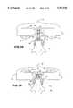
- Eyeglass displays having a nose bridge 1 that can be adjusted in and out to control the distance between the wearer's eyes and the video display portions 2 of the eyeglass displaysare shown in FIG. 1 and described in U.S. Pat. No. 5,815,126, entitled “Monocular Portable Communication and Display System.”
- This adjustable nose bridgeallows the wearer to select the optimal viewing distance between the eye and the display portion of the eyeglass display despite variations in the wearer's facial structure and vision.
- FIG. 2A and FIG. 2Bare shown in FIG. 2A and FIG. 2B and additionally described in U.S. Pat. No. 4,280,758.
- Adjusting the height of bifocalsallows the wearer to position the lower (reading) lenses 3 of the bifocal glasses 4 where they are most convenient for the task at hand.
- a wearermight prefer the reading lenses low so she could conveniently look down through the reading lenses at the book without having to tilt her head down in an exaggerated way to interpose the reading lenses between her eyes and the book.
- the lowered reading lensesallow the wearer to look forward through the upper (long distance) lenses 5 at her surroundings.
- a wearer using a computermight prefer the reading lenses 3 raised in order to view a computer screen through the reading lenses without tilting her head back to interpose the reading lenses between her eyes and the computer screen.
- Adjusting the height of an eyeglass displaymay also offer certain advantages. For example, wearing an eyeglass display low on the face would allow the wearer to make eye contact with another person while conversing. At the same time, the lowered eyeglass display could allow the wearer to glance down and view data relevant to the conversation displayed on the eyeglass display. Alternatively, the lowered eyeglasses may be preferred by a wearer who spends a great deal of time viewing data through the displays so that she may remain aware of her surroundings by looking over the top of the eyeglass display.
- a wearermight choose to wear the eyeglass display high on the face. This configuration might be convenient for those who work with their hands and follow complex procedures such as doctors or mechanics.
- the raised eyeglass displaymay be used, for example, to show instructions, diagrams, or alternate views of the subject to the wearer. At the same time, the wearer's hands, any instruments or tools, and the subject of the instructions are in full view below the eyeglass display.
- the wearer's viewing anglewill not remain perpendicular to the plane of the displayed image when the display is moved above or below eye level.
- the eyeglass displaysshould include an adjustment for tilt. The tilt adjustment would allow the optimal perpendicular viewing angle to be achieved at whatever height the wearer chooses to wear the eyeglass display.
- a nose bridge for an eyeglass displaywhich can be used to adjust the height of the display on the face, the tilt of the display, and the distance between the eye and the display.
- the inventionprovides an articulated nose bridge for a head mounted display having a left eye display, a right eye display, and a bridge connecting the left eye display to the right eye displays.
- the articulated nose bridge according to the inventionallows easy adjustment of the height of the display on the wearer's face, the tilt of the display, and the viewing distance between the wearer's eyes and the display.
- the articulated nose bridge according to the inventionincludes a nose piece configured to rest on a wearer's nose, a bridge piece located between the left eye display and the right eye display, and an articulator.
- the articulatorhas a nose end coupled to the nose piece, and a bridge end pivotally coupled to the bridge piece allowing the viewing angle of the left and right eye displays to be adjusted by the wearer.
- the adjustable nose bridgemay additionally include a locking mechanism having a locked position, preventing the bridge piece from pivoting, and a free position, allowing the bridge piece to pivot.
- the locking mechanismmay include a spring configured to automatically return the locking mechanism to the locked position from the free position.
- the nose end of the articulatormay be pivotally coupled to the nose piece.
- the bridge piecemay include a gear segment and the locking mechanism may include a pawl configured to engage the gear segment when in the locked position.
- the pawl engages with the gear segmentprevents the bridge piece from pivoting relative to the articulator when the locking mechanism is in the locked position.
- the pawlmay be affixed to the articulator or may be free to move in one dimension within the articulator.
- the articulatormay include a bridge segment and a nose segment.
- the bridge segmentincludes the bridge end of the articulator and additionally includes a first end and a second end.
- the nose segmentincludes the nose end of the articulator and additionally includes a third end and a fourth end that is pivotally coupled to the second end of the bridge segment.
- the locking mechanismmay prevent the nose segment from pivoting about the second end of the bridge segment when the locking mechanism is in the locked position.
- the fourth end of the nose segmentmay include a second gear segment, and the pawl may be configured to engage the second gear segment when in the locked position.
- the fourth end of the nose segmentmay alternately be configured to slip over a portion of the bridge segment from the second end allowing adjustment of the length of the articulator by longitudinally adjusting the portion of the bridge segment inserted into the nose segment.
- the locking mechanismmay prevent the bridge segment from moving longitudinally within the nose segment when the locking mechanism is in the locked position.
- the second end of the bridge segmentmay be configured to expand against at least one internal surface of the nose segment when an internal pressure is applied to the second end of the bridge segment.
- the locking mechanismmay include a wedge for applying the internal pressure to the second end when the locking mechanism is in the locked position.
- the bridge piecemay define a first through hole
- the articulatormay include a nose segment and a bridge segment that defines a second through hole.
- the locking mechanismmay include a tensioner and a cable including a cable end affixed to the nose segment. The cable passes through the first through hole and the second through hole. The tensioner pulls the cable end toward the bridge piece when the locking mechanism is in the locked position. Thus, the tensioning force may compress the bridge segment against the bridge piece.
- An intermediate section defining a third through holemay be interposed between the nose segment and the bridge segment having the cable passes though the third through hole.
- FIG. 1is a perspective view of a prior art head mounted display featuring an adjustable nose bridge.
- FIG. 2Ais a front elevation view of prior art bifocal glasses featuring an adjustable nose bridge in a lowered position.
- FIG. 2Bis a front elevation view of the prior art bifocal glasses of FIG. 2A depicting the adjustable nose bridge in a raised position.
- FIG. 3Ais a front elevation view of a head mounted display with an articulated nose bridge according to the invention worn high on the face.
- FIG. 3Bis a front elevation view of a head mounted display with an articulated nose bridge according to the invention worn low on the face.
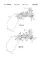
- FIG. 3Cis a side view of an articulated nose bridge according to the invention keeping a head mounted display at eye level for a wearer with a large nose and deep set eyes.
- FIG. 3Dis a side view of an articulated nose bridge according to the invention keeping a head mounted display tilted downward on the face for a wearer with a large nose and deep set eyes.
- FIG. 3Eis a side view of an articulated nose bridge according to the invention keeping a head mounted display tilted upward on the face for a wearer with a large nose and deep set eyes.
- FIG. 3Fis a side view of an articulated nose bridge according to the invention keeping a head mounted display at eye level for a wearer with a small nose and a flat face.
- FIG. 3Gis a side view of an articulated nose bridge according to the invention keeping a head mounted display tilted downward for a wearer with a small nose and a flat face.
- FIG. 3His the side view of the articulated nose bridge depicted in FIG. 3F with the head mounted display held closer to the eyes of the wearer.
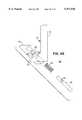
- FIG. 4Ais a perspective view of the first embodiment of the articulated nose bridge according to the invention.
- FIG. 4Bis a side view of the first embodiment of an articulated nose bridge according to the invention with the locking mechanism in a locked position.
- FIG. 4Cis a side view of the first embodiment of an articulated nose bridge according to FIG. 4B with the locking mechanism in a free position.
- FIG. 4Dis a plan view of the first embodiment depicted in FIG. 4B.
- FIG. 4Eis a plan view of the first embodiment depicted in FIG. 4C.
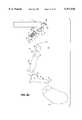
- FIG. 4Fis an exploded view of the first embodiment depicted in FIG. 4B and FIG. 4C.
- FIG. 4Gis an exploded view of the locking mechanism depicted in FIG. 4F.
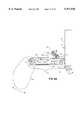
- FIG. 5Ais a perspective view of the second embodiment of the articulated nose bridge according to the invention.
- FIG. 5Bis a side view of the second embodiment of the articulated nose bridge according to the invention with the locking mechanism in a locked position.
- FIG. 5Cis a side view of the second embodiment of the articulated nose bridge according to the invention with the locking mechanism in a free position.
- FIG. 5Dis an exploded view of the second embodiment of the invention as depicted in FIG. 5A, FIG. 5B, and FIG. 5C.
- FIG. 6Ais a side view of the third embodiment of an articulated nose bridge according to the invention with the locking mechanism in the locked position.
- FIG. 6Bis a side view of the third embodiment of an articulated nose bridge according to the invention with the locking mechanism in the free position and the nose segment extended.
- FIG. 6Cis a side view of the third embodiment of an articulated nose bridge according to the invention with the locking mechanism in the free position and the nose segment retracted.
- FIG. 7Ais a side view of the fourth embodiment of an articulated nose bridge according to the invention with the locking mechanism in the locked position.
- FIG. 7Bis a side view of the fourth embodiment of the articulated nose bridge according to the invention with the locking mechanism in the free position.
- FIG. 8Ais a side view of the fifth embodiment of an articulated nose bridge according to the invention with the locking mechanism in the locked position.
- FIG. 8Bis a side view of the fifth embodiment of an articulated nose bridge according to the invention with the locking mechanism in the free position.
- the inventionprovides an articulated nose bridge that can be used to adjust the position of a head mounted display relative to the eyes of the wearer.
- the articulated nose bridge according to the inventionallows wearers having a variety of facial shapes to adjust the head mounted display to a number of facial positions while keeping the eye display perpendicular to the line of sight of the wearer.
- Some embodiments of the articulated nose bridge according to the inventionalso allows the wearer to adjust the distance between the head mounted display and the wearer's eye in any facial position selected by the wearer.
- FIG. 3A through FIG. 3Hdepict various positions to which the head mounted display can be adjusted to using an articulated nose bridge according to the invention.
- the articulated nose bridge depicted in these figuresis according to the second embodiment 31 of the invention that will be discussed in detail below.
- FIG. 3A and FIG. 3Bare elevation views depicting a head mounted display with an articulated nose bridge according to the second embodiment of the invention worn high on the face and low on the face, respectively.
- a wearer's head 6is depicted by a nose 7 and eyes 8.
- the head mounted display 10includes the left eye display 11 and the right eye display 70 connected via a bridge 12.
- the articulated nose bridge 13 according the inventionincludes a nose piece 14, a bridge piece 15, and an articulator 16.
- the nose pieceis configured to rest on the wearer's nose 7 and the bridge piece is either attached to or integral with the bridge 12, located between the left and right eye displays 11, 70 of the head mounted display 10.
- the articulatorhas a nose end 17 coupled to the nose piece 14 and a bridge end 18 pivotally coupled to the bridge piece 15.
- FIGS. 3C through 3Hdepict the use of an articulated nose bridge according to the a second embodiment of the invention 31 to adjust the head mounted display 10, of which it forms part, to a variety of positions on a variety of facial types.
- the left side of the wearer's head 6is depicted by the nose 7, in profile, and the eye 8 having a line of sight 9.
- the head mounted display 10 in the figuresincludes the left eye display 11 depicted as a transparent box so that the articulated nose bridge 13 can be shown.
- bridge piece 15, and articulator 16these figures also depict a first pivot pin 19 and a second pivot pin 20.
- the first pivot pin 19couples the nose end 17 of the articulator 16 to the nose piece 14.
- the second pivot pin 20couples the bridge end 18 of the articulator to the bridge piece 15.
- FIG. 3C, FIG. 3D, and FIG. 3Edepict the wearer 6 having a large nose 7 and eyes 8 set back deep in the head, away from the nose.
- the articulated nose bridge 13has been adjusted to position the head mounted display 10 at eye level on the wearer's face, and to tilt the head mounted display to an angle at which the front of the eye display 11 is perpendicular to the wearer's line of sight 9.
- FIG. 3Dthe articulated nose bridge 13 has been adjusted to position the head mounted display 10 low on the wearer's face, and to tilt the head mounted display to an angle at which the front of the eye display 11 is perpendicular to the wearer's line of sight 9.
- the articulated nose bridge 13has been adjusted to position the head mounted display 10 high on the wearer's face, and to tilt the head mounted display to an angle at which the front of the eye display 11 is perpendicular to the wearer's line of sight 9.
- FIGS. 3F through 3Hdepict the wearer 6 having a smaller nose 7 and eyes 8 that are closer to the nose 7 indicating a flat face.
- the articulated nose bridge 13has been adjusted to position the head mounted display 10 at eye level on the wearer's face, and to tilt the head mounted display to an angle at which the front of the eye display 11 is perpendicular to the wearer's line of sight 9.
- the articulated nose bridge 13has been adjusted to position the head mounted display 10 low on the wearer's face, and to tilt the head mounted display to an angle at which the front of the eye display 11 is perpendicular to the wearer's line of sight 9.
- the ability of the articulated nose bridge 13 according to the invention to adjust to a number of facial positions while keeping the eye display 11 perpendicular to the line of sight 9 on a variety of facial shapeshas been shown.
- the examplesalso show that the articulated nose bridge 13 can be adjusted to keep the eye display 11 at a constant distance D from the wearer's eye 8.
- FIG. 3His similar to FIG. 3F inasmuch as the articulated nose bridge 13 has been adjusted to position the head mounted display 10 at eye level on the wearer's face, and to tilt the head mounted display to an angle at which the front of the eye display 11 is perpendicular to the wearer's line of sight 9.
- the articulated nose bridge 13has been adjusted to set the distance between the eye display 11 and the eye 8 to the smaller distance D1.
- This figureshows that the articulated nose bridge according to the invention can provide distance control in addition to height and tilt control of the head mounted display.
- the articulated nose bridge 13may be held in each of the positions shown in FIGS. 3A through 3H or in any intermediate position by friction or by a locking mechanism, described in detail below. While each of the embodiments of the articulated nose bridge 13 described below includes a locking mechanism 22, it is understood that each embodiment may be altered so that friction holds the articulated nose bridge 13 in its adjusted position.
- FIG. 4A through FIG. 4Gshow a first embodiment 21 of the articulated nose bridge according to the invention.
- FIG. 4Adepicts a perspective view of the first embodiment of the articulated nose bridge.
- FIG. 4B and FIG. 4Cdepict a side view of the first embodiment 21 of the articulated nose bridge with a locking mechanism 22 in a locked position and a free position, respectively.
- FIG. 4D and FIG. 4Edepict a plan view of the first embodiment 21 of the articulated nose bridge depicted in FIG. 4B and FIG. 4C, respectively.
- FIG. 4Fis an exploded view of the first embodiment 21 of the articulated nose bridge
- FIG. 4Gis an exploded view of a portion of the locking mechanism 22.
- the first embodiment 21 of the articulated nose bridgehas a simplified, single beam articulator structure as opposed to the two segment structure of the second embodiment 31, depicted in FIG. 3A through FIG. 3H and discussed in detail below.
- the simplified structurereduces manufacturing and assembly costs of the first embodiment 21 while retains the ability to adjust the height and tilt of the head mounted display 10 on the wearer's face. It is noted, however, that the first embodiment 21 of the articulated nose bridge lacks the ability found the other embodiments to adjust the distance between the eye displays 11, 70 and the wearer's eyes 8 (shown in FIG. 3A).
- the first embodiment 21 of the articulated nose bridgeincludes the nose piece 14 configured to rest on a wearer's nose 7, the bridge piece 15 attached to or integral with the bridge 12 located between the left and right eye displays 11, 70, and the articulator 16.
- the bridge piece 15includes a main body 71, a locking mechanism housing 72 projecting from the main body and a pivot body 73 projecting from the main body.
- the pivot body 73defines a slot 24 through the pivot body.
- the pivot bodyincludes a gear segment 23 remote from the main body 71.
- the gear segmenthas an outer circumference 74 (shown in FIG. 4G).
- the articulator 16which preferably has a "U"-shaped cross-section and is made from folded sheet metal, has a nose end 17 coupled to the nose piece 14 by a first pivot pin 19 and a bridge end 18 pivotally coupled to the bridge piece 15 by a second pivot pin 20.
- the first pivot pin 19 and second pivot pin 20are shown in black in FIG. 4B and FIG. 4C and with hash marks in FIG. 4D and FIG. 4E for clarity.
- the first pivot pinis preferably configured such that the wearer can pivot nose piece 14 about the first pivot pin 19 and the nose piece will remain in the adjusted position due to friction.
- the first embodiment 21 of the articulated nose bridgeadditionally includes a locking mechanism 22.
- the locking mechanismincludes a push button 25 (shown with hash marks for clarity in FIG. 4B, FIG. 4C, and FIG. 4F), spring 26, and pawl 27 (shown with hash marks for clarity in FIG. 4D and FIG. 4E).
- the spring 26is preferably a compression spring.
- Defined in the push button 25is a hole 28 dimensioned to receive the second pivot pin 20 (see FIG. 4D and FIG. 4E).
- the push button 25 and spring 26fit into a channel 29 formed in the locking mechanism housing 72.
- the channel 29is parallel to slot 24 defined in the pivot body 73.
- the channelis configured such that when the push button is in channel 29, the second pivot pin 20 can pass through slot 24 and into hole 28.
- the pawl 27is affixed to the articulator 16 and is configured to engage with the gear segment 23 when the locking mechanism 22 is in the locked position.
- a pawlis "engaged" with a gear segment when a portion of the pawl is located within the outer circumference of the gear segment.
- pawl 27is engaged with gear segment 23 because it is disposed within the outer circumference 74 of gear segment 23.
- the pawlprevents the bridge piece 15 from pivoting around the second pivot pin 20. While backlash between the pawl and the gear segment may result in some trivial pivoting of the bridge piece around the second pivot pin 20, for purposes of this description, such pivoting is not considered “pivoting.”
- the spring 26moves the push button axially along the channel 29 in a first direction opposite that indicated by arrow 30 in FIG. 4C and FIG. 4E.
- the push button 25moves the second pivot pin 20 in the first direction along a length of slot 24 and pulls the articulator 16 closer to the gear segment 23 until the pawl 27 is engaged with gear segment.
- This conditionis called the locked position of the locking mechanism 22 and is depicted in FIG. 4A, FIG. 4B, and FIG. 4D.
- the locking mechanismprevents the bridge piece 15 from substantially pivoting around the second pivot pin 20.
- the spring 26, gear teeth 23, pawl 27are configured to require the wearer to push the push button 25 to move the locking mechanism 22 into the free position.
- Certain spring, gear teeth, and pawl configurationswill allow the locking mechanism 22 to operate like a detent system.
- the force required to pivot the bridge piecealso overcomes the force exerted by the spring 26 allows the pawl to slide up the adjacent gear tooth of the gear segment 23 until it disengages from the gear segment.
- the spring 26forces the pawl back into engagement with the gear segment 23, thus moving the locking mechanism back into the locked position.
- first pivot pin 19pivotally couple the nose piece 14 to the articulator 16 to provide the wearer with the ability to adjust the angle of the nose piece 14 to the most comfortable angle
- FIG. 5A through FIG. 5Dshow a second embodiment 31 of the articulated nose bridge according to the invention.
- FIG. 5Adepicts a perspective view of the second embodiment 31 of the articulated nose bridge according to the invention.
- FIG. 5B and FIG. 5Cdepict a side view of the second embodiment 31 of the articulated nose bridge with a locking mechanism 22 in a locked position and an free position, respectively.
- FIG. 5Dis an exploded view of the second embodiment 31 of the articulated nose bridge.
- the second embodiment 31 of the articulated nose bridgeis structurally similar to the first embodiment 21 discussed above. To the extent that elements of the second embodiment are identical to the elements of the first embodiment 21, previously described and depicted in FIG. 4A though FIG. 4G, they will be indicated with identical reference numerals in FIGS. 5A though 5D, and will not be described again below.
- the articulator 16includes a bridge segment 33 and a nose segment 34.
- the bridge segment 33has a first end 35 that includes the bridge end 18 of the articulator and a second end 36.
- the bridge segmentpreferably is made of sheet metal and has a "U"-shaped cross-section at the first end 35 and second end 36 and a box cross-section between the first end and the second end.
- the nose segment 34has a third end 37 that includes the nose end 17 of the articulator and a fourth end 38.
- the fourth end 38 of the nose segment 34is pivotally coupled to the second end 36 of the bridge segment 33 with a third pivot pin 39.
- pawl 32A second significant difference between second embodiment 31 and the first embodiment 21 is pawl 32.
- the pawl 32is configured to engage the gear segment 23 (also called “first gear segment” below) formed in pivot body 73 when the locking mechanism is in the locked position.
- the pawl 32when engaged with the first gear segment 23, prevents the bridge piece 15 from substantially pivoting around the second pivot pin 20.
- pawl 32 of the second embodiment 31is not affixed to the articulator 16, but is instead constrained within the box cross-section of the bridge segment 34 of the articulator, such that it is free to move axially within the bridge segment.
- the pawl 32preferably has a rectangular cross section that fits within the box cross-section of the bridge segment 34 and has a first engaging portion 76 and second engaging portion 77 (shown in FIG. 5D).
- the first engaging portion 76is the portion of the pawl that is configured to engage the first gear segment 23 when the locking mechanism 22 is in the locked position as described above.
- the second engaging portion 77 of the pawl 32is configured to engage a second gear segment 40 when the locking mechanism is in the locked position.
- the second gear segmentwill be described below.
- the locking mechanism 22 of the second embodiment 31 when in the locked positionalso prevents the nose segment 34 from pivoting about the third pivot pin 39 in the second end 36 of the bridge segment 33.
- the second gear segment 40is formed in fourth end 38 of the nose segment 34.
- the spring 26moves the push button along the channel 29 in the first direction, opposite the direction of the arrow 30.
- the push button 25moves the second pivot pin 20 in the first direction along slot 24.
- the second pivot pinpulls the bridge segment 33 of the articulator 16 closer to the pivot body 73, and moves the second gear segment 40 closer to the first gear segment 23.
- the bridge segmentmoves closer to the pivot body until the pawl 32 is engaged with both the first gear segment 23 and the second gear segment 40. This condition is called the locked position of the locking mechanism 22 and is depicted in FIG. 5A and FIG. 5B.
- the spring 26, the first gear segment 23, the second gear segment 40, and the pawl 27are configured to require the wearer to depress the push button 25 to move the locking mechanism into the free position.
- certain spring, first gear segment, second gear segment, and pawl configurationswill allow the locking mechanism 22 to operate like a detent system.
- the force required to pivot the bridge piece or nose segmentovercomes the force of spring 26 and allows the pawl to slide up the side of an adjacent tooth of either the first gear segment 23 or the second gear segment 40 until it is no longer engaged.
- the spring 26moves the pawl back into engagement with both the first gear segment 23 and the second gear segment 40, thus moving the locking mechanism back into the locked position.
- FIG. 6A through FIG. 6Cshow a third embodiment 41 of the articulated nose bridge according to the invention.
- FIG. 6Adepicts a side view of the third embodiment 41 of the articulated nose bridge with a locking mechanism 22 in a locked position.
- the third embodiment 41 of the articulated nose bridgeis structurally similar to the first and second embodiments 21, 31 discussed above except for the articulator 16 and the pawl 43. To the extent that elements of the third embodiment are identical to the elements of the first two embodiments 21, 22 previously described and depicted in FIG. 4A though FIG. 5D, they will be indicated with identical reference numerals in FIGS. 6A though 5C, and will not be described again below.
- the pawl 43 in the third embodimentis different than the pawl 27 of the first embodiment 21 and the pawl 32 of the second embodiment.
- the pawl 43has a first engaging portion 78 configured to engage the first gear segment 23 when the locking mechanism is in the locked position and is free to move in one dimension within the bridge segment 44 of the articulator 16.
- the pawl 43prevents bridge piece 15 from pivoting around the second pivot pin 20.
- the pawl 43is also has an extended body portion 79 configured to prevent longitudinal movement within the articulator 16 when the locking mechanism is in the locked position as will be discussed in detail, below.
- the articulator 16includes a bridge segment 44 and a nose segment 42.
- the bridge segment 44has a first end 45 including the bridge end 18 of the articulator and a second end 46.
- the bridge segment 44is preferably made from folded sheet metal and has a "U"-shaped cross-section at the first end 45 and a box-shaped cross section at the second end 46 that constrains the pawl 43.
- the nose segment 42has a third end 47 that includes the nose end 17 of the articulator and a fourth end 48 configured to slip over a portion of the bridge segment 44 from the second end 46.
- Bridge segment 44is slipped into the nose segment 42 (longitudinal movement) to a varying degree, controlling the overall length of the articulator 16.
- the locking mechanism 22 of the third embodiment 41 when in the locked positionalso prevents the bridge segment 44 from moving longitudinally within the nose section 42 when the locking mechanism is in the locked position.
- the locking mechanismprevents the length of the articulator from changing while in the locked position.
- the second end 46 of the bridge segment 44is configured to expand against at least one internal surface 49 of the nose segment 42 when internal pressure is applied to the second end 46 of the bridge segment 44.
- the second end 46includes ramps 50 that expand the second end against the at least one internal surface 49 of the nose segment 42 when an internal pressure is applied.
- the extended body portion 79 of pawl 43is formed into a wedge 51.
- the wedge 51is configured to apply the internal pressure to the second end 46 when the locking mechanism is in the locked position by forcing the ramps 50 toward the at least one internal surface 49 of the nose segment 42.
- the first engaging portion 78 of pawl 43engages with the gear segment 23 and, the wedge 51 moves the ramps toward the at least one inner surface 49 of the nose segment.
- the locking mechanismthus prevents both longitudinal movement of the bridge segment 44 within the nose segment 42 and prevents the bridge piece 15 from pivoting about the second pivot pin 20.
- the spring 26moves the push button along the channel 29 in a direction opposite that of the arrow 30 in FIG. 6B and FIG. 6C.
- the push button 25moves the second pivot pin 20 along slot 24.
- the second pivot pin 20pulls the bridge segment 44 of the articulator 16 closer to the pivot body 73, and moves ramps 50 closer to the gear segment 23.
- the bridge segmentmoves closer to the pivot body 73 until the pawl 43 engages with the gear segment 23 and the wedge 52 has pushed the ramps 50 toward the internal surface 49 of the nose segment 43. This condition is called the locked position of the locking mechanism 22 and is depicted in FIG. 6A.
- FIG. 7A and FIG. 7Bshow a fourth embodiment 52 of the articulated nose bridge according to the invention.
- FIG. 7Adepicts a side view of the fourth embodiment 52 of the articulated nose bridge with the locking mechanism 22 in a locked position.
- FIG. 7Bdepicts a side view of the fourth embodiment 52 of the articulated nose bridge with the locking mechanism a free position.
- the fourth embodiment 52 of the articulated nose bridgeis structurally similar to the previously described second embodiment 31. To the extent that elements of the fourth embodiment are identical to the elements of the second embodiment 31, previously described and depicted in FIG. 5A though FIG. 5D, they will be indicated with identical reference numerals in FIG. 7A and FIG. 7B, and will not be described again below.
- the bridge piece 15includes the main body 71 and the pivot body 73.
- the pivot bodypreferably defines a first curved face 81 remote from the main body 71 and defines a first through hole 58 passing through the pivot body 73 from the first curved face 81.
- the articulator 16 of the fourth embodiment 52has a bridge segment 54 and a nose segment 53.
- the bridge segment 54has a first end 82 including the bridge end 18 and a second end 83.
- the first end 82preferably defines a second curved face 84 shaped to fit tightly against the first curved face 81 of the pivot body 73.
- the second end 83preferably defines a third curved face 85.
- the bridge segment 54additionally defines a second through hole 56 that passes from the second curved face 84 to the third curved face 85.
- the nose segment 53 of the fourth embodimenthas a third end 86 including the nose end 17 and a fourth end 87.
- the fourth endpreferably defines a fourth curved face 88 shaped to fit tightly against the third curved face 85 of the bridge segment 54.
- the pivot body 73 and the bridge segment 54are preferably configured to prevent the first curved face 81 of the pivot body from sliding against the second curved face 84 of the bridge segment when the first curved face and the second curved face are pressed together tightly.
- the bridge segment 54 and the nose segment 53are preferably configured to prevent the third curved face 85 of the bridge segment 54 from sliding against the fourth curved face 88 of the nose segment 53 when the third curved face and the fourth curved face are pressed together tightly.
- the locking mechanism 22 of the fourth embodiment 52includes the push button 25, a cable 59 and a tensioner 60 that is preferably a compression spring.
- the cablehas a first cable end 61 attached to the push button and a second cable end 62 attached to the nose segment 53. From the first cable end 61, the cable 59 passes through the tensioner 60, the first through hole 58 in the pivot body 73, and the second through hole 56 in the bridge segment 54.
- the tensioner 60moves the push button 25 and the first cable end 61 away from the bridge piece 15 in a direction opposite the arrow 30 in FIG. 7B.
- Thismoves the nose segment 53 and the second cable end 62 toward the first curved face 81 of the pivot body 73.
- the nose segment 53continues to move toward the first curved face 81 until the bridge segment 54 is compressed between the nose segment 53 and the pivot body 73 with the first curved face 81 pressed tightly against the second curved face 84 and the third curved face 85 pressed tightly against the fourth curved face 88.
- This conditionis called the locked position of the locking mechanism 22 and is depicted in FIG. 7A.
- the locking mechanismprevents the first curved face 81 from sliding against the second curved face 84 and thus prevents the bridge piece 15 from pivoting against the bridge segment 54. Additionally, in the locked position, the locking mechanism prevents the third curved face 85 from sliding against the fourth curved face 88 and thus prevents the nose segment 53 from pivoting against the bridge segment 54.
- the cable 59couples and aligns the nose segment 53, bridge segment 54, and the bridge piece 15, but the flexibility of the cable allows both the nose segment to pivot around the second end 83 of the bridge segment and the bridge piece 15 to pivot around the first end 82 of the bridge segment.
- FIG. 8A and FIG. 8Ba fifth embodiment 80 of the articulated nose bridge according to the invention is depicted.
- FIG. 8Adepicts a side view of the fifth embodiment 80 of the articulated nose bridge with the locking mechanism 22 in a locked position.
- FIG. 8Bdepicts a side view of the fifth embodiment 80 of the articulated nose bridge with the locking mechanism 22 in a locked position.
- the fifth embodiment 80 of the articulated nose bridgeis structurally similar to the previously described fourth embodiment 52. To the extent that elements of the fifth embodiment are identical to the elements of the fourth embodiment 53, previously described and depicted in FIG. 7A and FIG. 7B, they will be indicated with identical reference numerals in FIG. 8A and FIG. 8B, and will not be described again below.
- the primary difference between the fourth embodiment 52 and the fifth embodiment 80 of the articulated nose bridgeis the addition of an intermediate section 55 between the nose segment 53 and the bridge segment 54 of the articulator 16.
- the addition of the intermediate section 55allows the articulator to have additional flexibility and provides a greater number of adjustment possibilities to the wearer.
- the articulator 16 of the fifth embodiment 80includes the nose segment 53, the bridge segment 54, and an intermediate section 55.
- the intermediate section 55defines a nose curved face 89, a bridge curved face 90 and a third through hole 57 running from the nose curved face to the bridge curved face.
- the bridge curved face 90is preferably shaped to fit tightly against the third curved face 85 of the bridge segment 54.
- the nose segment 53 of the fifth embodiment 80differs from the nose segment of the fourth embodiment 53 inasmuch as the fourth curved face 88 in the fifth embodiment is shaped to fit tightly against nose curved face 89 rather than the third curved face 85.
- the bridge segment 54 and the intermediate section 55are preferably configured to prevent the third curved face 85 of the bridge segment 54 from sliding against the bridge curved face 90 of the intermediate section 55 when the third curved face and the bridge curved face are pressed together tightly.
- the nose segment 53 and the intermediate section 55are preferably configured to prevent the fourth curved face 88 of the nose segment 53 from sliding against the nose curved face 89 of the intermediate section 55 when the fourth curved segment and the nose curved segment are pressed together tightly.
- the intermediate section 55does not have to be a single body. It is preferred that the intermediate section 55 include a number (three are shown in FIG. 8A and FIG. 8B) of intermediate bodies 91, 92, 93, each intermediate body having a mating curved surface 94 configured to fit tightly against the mating curved surface of an adjacent intermediate body.
- the first intermediate body 91is adjacent the nose section 53 and includes the nose curved face 89.
- the third intermediate body 93is adjacent the bridge segment 54 and includes the bridge curved face 90.
- the second intermediate body 92includes two mating curved surfaces 94.
- every other intermediate bodyfirst and third intermediate bodies 91, 93
- the locking mechanism 22 of the fifth embodiment 80includes the push button 25, the cable 59 and the tensioner 60.
- the cablehas a first cable end 61 attached to the push button and a second cable end 62 attached to the nose segment 53. From the first cable end 61, the cable 59 passes through the tensioner 60, the first through hole 58 in the pivot body 73, the second through hole 56 in the bridge segment 54, and the third through hole 57 in intermediate section 55.
- the tensioner 60moves the push button 25 and the first cable end 61 away from the bridge piece 15 in a direction opposite the arrow 30 in FIG. 8B.
- Thismoves the nose segment 53 and the second cable end 62 toward the first curved face 81 of the pivot body 73.
- the nose segment 53moves toward the first curved face 81 until the fourth curved face 88 strikes the nose curved face 89 of the intermediate section 55.
- the nose segment 53 and intermediate section 55then move toward the pivot body 73 until the bridge curved face 90 of the intermediate section strikes the third curved face 85 of the bridge segment 54.
- the bridge segment 54, the intermediate section 55, and the nose segment 53then move toward the pivot body until the second curved face 84 of the bridge segment 54 strikes the first curved face 81 of the pivot body 73.
- the nose segment 53then continues to move toward the pivot body until the fourth curved face 88 fits tightly against the nose curved face 89, the mating curved faces 94 fit tightly together, the bridge curved face 90 fits tightly against the third curved face 85, and the second curved face 84 fits tightly against the first curved face 81.
- This conditionis called the locked position of the locking mechanism 22 and is depicted in FIG. 8A.
- the locking mechanismprevents the first curved face 81 from sliding against the second curved face 84 and thus prevents the bridge piece 15 from pivoting against the bridge segment 54.
- the locking mechanismprevents the third curved face 85 from sliding against bridge curved face 90 and prevents the fourth curved face 88 from sling against the nose curved face 89 and thus prevents articulation of the articulator 16.
- the push button 25moves toward the bridge piece 15 and compresses the tensioner 60 between the push button and the bridge piece 15. This moves the first cable end 61 toward the bridge piece 15, which released the tension in the cable 59. This allows the second cable end 62 and the nose segment 53 to move away from the pivot body 73, thus separating and the nose segment from intermediate section 55. Once the nose segment 53 moves away from the intermediate section, the intermediate section can move away from the bridge segment 54 along the cable 59, thus separating the intermediate section and the bridge segment. Once the intermediate section has moved away from the bridge segment, the bridge segment can move away from the pivot body 73 along the cable 59, thus separating the bridge segment and the pivot body.
- This conditionis called the free position of the locking mechanism 22 and is depicted in FIG. 8B.
- the cable 59couples and aligns the nose segment 53, intermediate section 55, bridge segment 54, and the bridge piece 15, but the flexibility of the cable allow the nose segment to pivot around the intermediate section 55, the intermediate section to pivot around the second end 83 of the bridge segment 54, and the bridge piece 15 to pivot around the first end 82 of the bridge segment.
Landscapes
- Physics & Mathematics (AREA)
- Health & Medical Sciences (AREA)
- General Physics & Mathematics (AREA)
- Ophthalmology & Optometry (AREA)
- Optics & Photonics (AREA)
- Eyeglasses (AREA)
- Dental Prosthetics (AREA)
Abstract
Description
Claims (21)
Priority Applications (3)
| Application Number | Priority Date | Filing Date | Title |
|---|---|---|---|
| US09/183,735US5971538A (en) | 1998-10-30 | 1998-10-30 | Articulated nose bridge for head mounted display |
| JP2000580038AJP4327364B2 (en) | 1998-10-30 | 1999-08-31 | Articulated nose bridge for head mounted display |
| PCT/US1999/019969WO2000026714A1 (en) | 1998-10-30 | 1999-08-31 | Articulated nose bridge for head mounted display |
Applications Claiming Priority (1)
| Application Number | Priority Date | Filing Date | Title |
|---|---|---|---|
| US09/183,735US5971538A (en) | 1998-10-30 | 1998-10-30 | Articulated nose bridge for head mounted display |
Publications (1)
| Publication Number | Publication Date |
|---|---|
| US5971538Atrue US5971538A (en) | 1999-10-26 |
Family
ID=22674085
Family Applications (1)
| Application Number | Title | Priority Date | Filing Date |
|---|---|---|---|
| US09/183,735Expired - Fee RelatedUS5971538A (en) | 1998-10-30 | 1998-10-30 | Articulated nose bridge for head mounted display |
Country Status (3)
| Country | Link |
|---|---|
| US (1) | US5971538A (en) |
| JP (1) | JP4327364B2 (en) |
| WO (1) | WO2000026714A1 (en) |
Cited By (72)
| Publication number | Priority date | Publication date | Assignee | Title |
|---|---|---|---|---|
| USD439266S1 (en) | 2000-10-27 | 2001-03-20 | Koalatech, Inc. | Eyeglasses with 3-D display panel |
| US6212020B1 (en)* | 1997-06-25 | 2001-04-03 | Ect Eye Control Technique Ab | Head-mounted carrier for positioning opto-electronic devices in front of the user's eyes |
| US6304234B1 (en)* | 1997-02-26 | 2001-10-16 | Olympus Optical Co., Ltd. | Information processing apparatus |
| US6330099B1 (en) | 2000-03-24 | 2001-12-11 | Agilent Technologies, Inc. | Liquid crystal apron and skirt isolation for silicon micro displays |
| US6439718B1 (en)* | 2001-01-29 | 2002-08-27 | Makoptica Patentees, Llc | Adjustable nose piece assembly for make-up eyeglasses |
| US6520636B2 (en)* | 2000-06-21 | 2003-02-18 | Youchi Kaihatsu Co., Ltd. | Nosepiece assembly for an adjustable eyeglass frame |
| USD502205S1 (en)* | 2002-09-28 | 2005-02-22 | Eston Bullard, Jr. | Adjustable eyeglass frames |
| US20070097021A1 (en)* | 1998-02-25 | 2007-05-03 | Semiconductor Energy Laboratory Co., Ltd. | Information processing device |
| USD565634S1 (en)* | 2005-02-19 | 2008-04-01 | Bullard Jr Eston | Adjustable eyeglass frame |
| US20090062008A1 (en)* | 1999-06-18 | 2009-03-05 | Karmarkar Jayant S | System for distributing entertaining episodes and crediting payouts to authorized remote-player's wagers |
| US20090195479A1 (en)* | 2006-09-19 | 2009-08-06 | Nikon Corporation | Output device and wearable display |
| US7591555B1 (en)* | 2008-09-02 | 2009-09-22 | Lin Yun Chen | Framework of combination of spectacle frames with lenses |
| US20100001928A1 (en)* | 2008-06-30 | 2010-01-07 | Honeywell International Inc. | Head-mountable cockpit display system |
| US20110096287A1 (en)* | 2008-06-16 | 2011-04-28 | Hardisty Optical Group, Llc | Light dispersion eyeglass nose pad |
| WO2011055155A1 (en)* | 2009-11-05 | 2011-05-12 | LŐRINCZ, Sándor | Free-horizon binocular image display device with integrated video signal source |
| USD651641S1 (en)* | 2009-09-28 | 2012-01-03 | Sperian Eye & Face Protection, Inc. | Nose piece assembly for safety eyewear |
| USD676897S1 (en)* | 2011-01-14 | 2013-02-26 | Lg Electronics Inc. | Bridge for 3D glasses |
| US20130088415A1 (en)* | 2011-10-07 | 2013-04-11 | Seiko Epson Corporation | Virtual image display device and manufacturing method of virtual image display device |
| TWI403153B (en)* | 2010-11-04 | 2013-07-21 | Hon Hai Prec Ind Co Ltd | Adjustable eyeglass frame of 3d eyeglass |
| US20140340285A1 (en)* | 2013-05-15 | 2014-11-20 | Seiko Epson Corporation | Virtual image display apparatus |
| US20150085372A1 (en)* | 2011-02-10 | 2015-03-26 | Sony Corporation | Display apparatus |
| JP2015069044A (en)* | 2013-09-30 | 2015-04-13 | ▲呉▼ 志民WU,Chih Ming | Glasses frame and glasses using the same |
| US9341862B1 (en)* | 2015-04-07 | 2016-05-17 | Trimax Safety Corp. | Eyeglasses having nose pad adjusting structure |
| US9366871B2 (en) | 2014-10-24 | 2016-06-14 | Emagin Corporation | Microdisplay based immersive headset |
| US9709817B2 (en) | 2015-12-07 | 2017-07-18 | Oakley, Inc. | Eyewear retention devices and methods |
| US9720258B2 (en) | 2013-03-15 | 2017-08-01 | Oakley, Inc. | Electronic ornamentation for eyewear |
| US9720240B2 (en) | 2006-12-14 | 2017-08-01 | Oakley, Inc. | Wearable high resolution audio visual interface |
| US9717631B2 (en) | 2012-08-31 | 2017-08-01 | Oakley, Inc. | Eyewear having multiple ventilation states |
| CN107024770A (en)* | 2016-12-01 | 2017-08-08 | 腾讯科技(深圳)有限公司 | Wearable device |
| US9864211B2 (en) | 2012-02-17 | 2018-01-09 | Oakley, Inc. | Systems and methods for removably coupling an electronic device to eyewear |
| US20180059434A1 (en)* | 2016-08-29 | 2018-03-01 | Osterhout Group, Inc. | Adjustable nose bridge assembly for headworn computer |
| US20180143451A1 (en)* | 2014-04-25 | 2018-05-24 | Osterhout Group, Inc. | Temple and ear horn assembly for headworn computer |
| US10018837B2 (en) | 2014-12-03 | 2018-07-10 | Osterhout Group, Inc. | Head worn computer display systems |
| US10018852B2 (en) | 2014-06-13 | 2018-07-10 | Visualign, Llc | Eyeglass positioning device |
| US10025119B2 (en) | 2015-06-18 | 2018-07-17 | Osterhout Group, Inc. | Mechanical arrangement for head-worn computer |
| WO2018129623A1 (en) | 2017-01-12 | 2018-07-19 | Brent Sheldon | Frame support member and frame support assembly for over-the-glasses (otg) eyewear |
| US10039445B1 (en) | 2004-04-01 | 2018-08-07 | Google Llc | Biosensors, communicators, and controllers monitoring eye movement and methods for using them |
| US10101588B2 (en) | 2014-04-25 | 2018-10-16 | Osterhout Group, Inc. | Speaker assembly for headworn computer |
| US20180299692A1 (en)* | 2017-04-14 | 2018-10-18 | Oakley, Inc. | Headworn supports having dynamic venting systems |
| US10120646B2 (en) | 2005-02-11 | 2018-11-06 | Oakley, Inc. | Eyewear with detachable adjustable electronics module |
| US10146772B2 (en) | 2014-04-25 | 2018-12-04 | Osterhout Group, Inc. | Language translation with head-worn computing |
| US10156734B2 (en) | 2015-12-08 | 2018-12-18 | Oakley, Inc. | Eyewear traction devices and methods |
| USD840395S1 (en) | 2016-10-17 | 2019-02-12 | Osterhout Group, Inc. | Head-worn computer |
| US10274748B2 (en) | 2014-03-27 | 2019-04-30 | Oakley, Inc. | Mounting mechanism for eyewear |
| US10288908B2 (en) | 2013-06-12 | 2019-05-14 | Oakley, Inc. | Modular heads-up display system |
| US10326918B2 (en) | 2015-08-31 | 2019-06-18 | Eayse Gmbh | Head-unit and system for interactive transmission of video and audio signals |
| US10359642B2 (en) | 2016-04-22 | 2019-07-23 | Oakley, Inc. | Mounting mechanism for eyewear |
| CN110082913A (en)* | 2018-01-26 | 2019-08-02 | 精工爱普生株式会社 | The nose support of virtual image display apparatus and virtual image display apparatus |
| US10379365B2 (en) | 2014-01-21 | 2019-08-13 | Mentor Acquisition One, Llc | See-through computer display systems |
| USD864959S1 (en) | 2017-01-04 | 2019-10-29 | Mentor Acquisition One, Llc | Computer glasses |
| US10466492B2 (en) | 2014-04-25 | 2019-11-05 | Mentor Acquisition One, Llc | Ear horn assembly for headworn computer |
| US10466491B2 (en) | 2016-06-01 | 2019-11-05 | Mentor Acquisition One, Llc | Modular systems for head-worn computers |
| US10520996B2 (en) | 2014-09-18 | 2019-12-31 | Mentor Acquisition One, Llc | Thermal management for head-worn computer |
| CN111123517A (en)* | 2018-10-30 | 2020-05-08 | 精工爱普生株式会社 | Head-mounted display device |
| US10684478B2 (en) | 2016-05-09 | 2020-06-16 | Mentor Acquisition One, Llc | User interface systems for head-worn computers |
| US10684687B2 (en) | 2014-12-03 | 2020-06-16 | Mentor Acquisition One, Llc | See-through computer display systems |
| US10687981B2 (en) | 2015-10-09 | 2020-06-23 | Oakley, Inc. | Headworn supports with passive venting and removable lens |
| US10698223B2 (en) | 2014-01-21 | 2020-06-30 | Mentor Acquisition One, Llc | See-through computer display systems |
| US10824253B2 (en) | 2016-05-09 | 2020-11-03 | Mentor Acquisition One, Llc | User interface systems for head-worn computers |
| US10853589B2 (en) | 2014-04-25 | 2020-12-01 | Mentor Acquisition One, Llc | Language translation with head-worn computing |
| US10890785B2 (en) | 2017-05-25 | 2021-01-12 | Jeffrey J. Browen | Eyeglass translating clip |
| EP3779566A1 (en)* | 2019-08-13 | 2021-02-17 | Pegatron Corporation | Glasses |
| US20210215950A1 (en)* | 2020-01-13 | 2021-07-15 | Six15 Technologies | Optics mount for over-the-glasses eyewear |
| US11095873B2 (en)* | 2017-09-22 | 2021-08-17 | Sony Interactive Entertainment Inc. | Head-mounted display |
| WO2022022497A1 (en)* | 2020-07-28 | 2022-02-03 | 维沃移动通信有限公司 | Eyeglass frame structure and wearable device |
| CN114236846A (en)* | 2021-12-27 | 2022-03-25 | 吉林省钜鸿智能技术有限公司 | AR glasses multifunctional frame |
| FR3115892A1 (en)* | 2020-11-03 | 2022-05-06 | Ny Lova RAFALIMANANA | Spectacle frame holder. |
| US11360324B2 (en)* | 2020-01-13 | 2022-06-14 | Hongfujin Precision Electronics (Zhengzhou) Co., Ltd. | Adjustable nose bridge and glasses having same |
| US11385472B2 (en) | 2016-09-30 | 2022-07-12 | Dolby Laboratories Licensing Corporation | 3D eyewear adapted for facial geometry |
| US11892644B2 (en) | 2014-01-21 | 2024-02-06 | Mentor Acquisition One, Llc | See-through computer display systems |
| US20240160037A1 (en)* | 2022-11-11 | 2024-05-16 | Htc Corporation | Wearable device |
| US12066861B1 (en)* | 2020-06-22 | 2024-08-20 | Apple Inc. | Nosepiece for head-mountable device |
Families Citing this family (9)
| Publication number | Priority date | Publication date | Assignee | Title |
|---|---|---|---|---|
| CA2875261C (en)* | 2012-06-01 | 2019-05-21 | Esight Corp. | Apparatus and method for a bioptic real time video system |
| JP6062669B2 (en)* | 2012-07-03 | 2017-01-18 | 日本電気株式会社 | Adjustment mechanism and adjustment method for head-mounted device |
| CN109407337B (en)* | 2018-12-20 | 2020-06-30 | 赣州通洲塑胶机械有限公司 | Nose pad |
| CN110262060B (en)* | 2019-04-08 | 2020-12-01 | 永康奈叶科技有限公司 | Glasses convenient to change |
| JP6882436B2 (en)* | 2019-12-09 | 2021-06-02 | 株式会社東芝 | Wearable device, system and display method |
| JP7263603B2 (en)* | 2019-12-09 | 2023-04-24 | 株式会社東芝 | WEARABLE TERMINAL, SYSTEM AND DISPLAY METHOD |
| KR102861634B1 (en)* | 2020-01-28 | 2025-09-18 | 삼성전자주식회사 | Head-mounted electronic device |
| CN111929918B (en)* | 2020-08-05 | 2022-06-14 | Oppo广东移动通信有限公司 | Nose pad subassembly and glasses |
| JP7581923B2 (en) | 2021-01-29 | 2024-11-13 | セイコーエプソン株式会社 | Attachments and head-mounted displays |
Citations (17)
| Publication number | Priority date | Publication date | Assignee | Title |
|---|---|---|---|---|
| US4190334A (en)* | 1978-08-28 | 1980-02-26 | Oneil Roderick J | Nose pad for eyeglass frames |
| US4280758A (en)* | 1978-11-02 | 1981-07-28 | Tom R. Flader | Vertically adjustable bifocal eye glasses |
| US4405213A (en)* | 1979-10-29 | 1983-09-20 | Ingeborg Kolkmann | Makeup eyeglasses with sliding frames |
| US4740069A (en)* | 1986-12-22 | 1988-04-26 | Baum Richard M | Eyeglasses for intermittent use |
| US4787729A (en)* | 1987-08-24 | 1988-11-29 | Ruffen Kenneth T | Eyeglass nose support |
| US4813776A (en)* | 1984-05-30 | 1989-03-21 | Borsos John D | Nose support for eyeglasses |
| US4834524A (en)* | 1984-05-30 | 1989-05-30 | Borsos John D | Nose support for eyeglasses |
| US4902119A (en)* | 1987-09-01 | 1990-02-20 | Optyl Eyewear Fashion International Corporation | Eyeglasses frame with articulated resilient nose piece |
| US5159359A (en)* | 1988-12-15 | 1992-10-27 | Essilor International Compagnie Generale | Eyeglass frame with spring biased nose bridge |
| US5680193A (en)* | 1996-02-26 | 1997-10-21 | Epstein; Harry | Positioning device for eyeglasses having bifocal lenses |
| US5691796A (en)* | 1995-11-02 | 1997-11-25 | Negishi; Tohru | Ophthalmic mounting for bifocal lenses |
| US5739893A (en)* | 1993-08-20 | 1998-04-14 | Seiko Epson Corporation | Head-mounted image display apparatus |
| US5757339A (en)* | 1997-01-06 | 1998-05-26 | Xybernaut Corporation | Head mounted display |
| US5774096A (en)* | 1994-04-21 | 1998-06-30 | Kabushiki Kaisha Sega Enterprises | Head mounted display |
| US5812224A (en)* | 1995-10-31 | 1998-09-22 | Olympus Optical Co., Ltd. | Head-mount image display apparatus |
| US5815126A (en)* | 1993-10-22 | 1998-09-29 | Kopin Corporation | Monocular portable communication and display system |
| US5880773A (en)* | 1991-12-27 | 1999-03-09 | Sony Corporation | Head mounted display configured to a user's physical features |
Family Cites Families (7)
| Publication number | Priority date | Publication date | Assignee | Title |
|---|---|---|---|---|
| US2112163A (en)* | 1937-11-06 | 1938-03-22 | George P Kimmel | Manipulative bridge for bifocal lenses |
| US2277726A (en)* | 1940-01-03 | 1942-03-31 | American Optical Corp | Ophthalmic mounting |
| US2578318A (en)* | 1948-01-31 | 1951-12-11 | Ronicker Harry | Vertically adjustable bifocal spectacles |
| DE1804431A1 (en)* | 1968-03-06 | 1971-06-09 | Textron Inc | Observation or viewing glasses and navigation methods for an aircraft |
| JPS5924824A (en)* | 1982-07-31 | 1984-02-08 | Toru Negishi | Multifocus glasses frame |
| US5291230A (en)* | 1992-11-17 | 1994-03-01 | Bradley James B | Ophthalmic device includes a detachable nosepiece |
| DE69531593T2 (en)* | 1994-06-23 | 2004-06-24 | Seiko Epson Corp. | INDICATOR ON THE HEAD |
- 1998
- 1998-10-30USUS09/183,735patent/US5971538A/ennot_activeExpired - Fee Related
- 1999
- 1999-08-31WOPCT/US1999/019969patent/WO2000026714A1/enactiveApplication Filing
- 1999-08-31JPJP2000580038Apatent/JP4327364B2/ennot_activeExpired - Fee Related
Patent Citations (17)
| Publication number | Priority date | Publication date | Assignee | Title |
|---|---|---|---|---|
| US4190334A (en)* | 1978-08-28 | 1980-02-26 | Oneil Roderick J | Nose pad for eyeglass frames |
| US4280758A (en)* | 1978-11-02 | 1981-07-28 | Tom R. Flader | Vertically adjustable bifocal eye glasses |
| US4405213A (en)* | 1979-10-29 | 1983-09-20 | Ingeborg Kolkmann | Makeup eyeglasses with sliding frames |
| US4813776A (en)* | 1984-05-30 | 1989-03-21 | Borsos John D | Nose support for eyeglasses |
| US4834524A (en)* | 1984-05-30 | 1989-05-30 | Borsos John D | Nose support for eyeglasses |
| US4740069A (en)* | 1986-12-22 | 1988-04-26 | Baum Richard M | Eyeglasses for intermittent use |
| US4787729A (en)* | 1987-08-24 | 1988-11-29 | Ruffen Kenneth T | Eyeglass nose support |
| US4902119A (en)* | 1987-09-01 | 1990-02-20 | Optyl Eyewear Fashion International Corporation | Eyeglasses frame with articulated resilient nose piece |
| US5159359A (en)* | 1988-12-15 | 1992-10-27 | Essilor International Compagnie Generale | Eyeglass frame with spring biased nose bridge |
| US5880773A (en)* | 1991-12-27 | 1999-03-09 | Sony Corporation | Head mounted display configured to a user's physical features |
| US5739893A (en)* | 1993-08-20 | 1998-04-14 | Seiko Epson Corporation | Head-mounted image display apparatus |
| US5815126A (en)* | 1993-10-22 | 1998-09-29 | Kopin Corporation | Monocular portable communication and display system |
| US5774096A (en)* | 1994-04-21 | 1998-06-30 | Kabushiki Kaisha Sega Enterprises | Head mounted display |
| US5812224A (en)* | 1995-10-31 | 1998-09-22 | Olympus Optical Co., Ltd. | Head-mount image display apparatus |
| US5691796A (en)* | 1995-11-02 | 1997-11-25 | Negishi; Tohru | Ophthalmic mounting for bifocal lenses |
| US5680193A (en)* | 1996-02-26 | 1997-10-21 | Epstein; Harry | Positioning device for eyeglasses having bifocal lenses |
| US5757339A (en)* | 1997-01-06 | 1998-05-26 | Xybernaut Corporation | Head mounted display |
Cited By (142)
| Publication number | Priority date | Publication date | Assignee | Title |
|---|---|---|---|---|
| US6304234B1 (en)* | 1997-02-26 | 2001-10-16 | Olympus Optical Co., Ltd. | Information processing apparatus |
| US6212020B1 (en)* | 1997-06-25 | 2001-04-03 | Ect Eye Control Technique Ab | Head-mounted carrier for positioning opto-electronic devices in front of the user's eyes |
| US7248232B1 (en)* | 1998-02-25 | 2007-07-24 | Semiconductor Energy Laboratory Co., Ltd. | Information processing device |
| US8605010B2 (en) | 1998-02-25 | 2013-12-10 | Semiconductor Energy Laboratory Co., Ltd. | Information processing device |
| US20070097021A1 (en)* | 1998-02-25 | 2007-05-03 | Semiconductor Energy Laboratory Co., Ltd. | Information processing device |
| US8123618B2 (en)* | 1999-06-18 | 2012-02-28 | Karmarkar Jayant S | Systems for distributing entertaining episodes and crediting payouts to authorized remote-player's wagers |
| US20090062008A1 (en)* | 1999-06-18 | 2009-03-05 | Karmarkar Jayant S | System for distributing entertaining episodes and crediting payouts to authorized remote-player's wagers |
| US6330099B1 (en) | 2000-03-24 | 2001-12-11 | Agilent Technologies, Inc. | Liquid crystal apron and skirt isolation for silicon micro displays |
| US6520636B2 (en)* | 2000-06-21 | 2003-02-18 | Youchi Kaihatsu Co., Ltd. | Nosepiece assembly for an adjustable eyeglass frame |
| USD439266S1 (en) | 2000-10-27 | 2001-03-20 | Koalatech, Inc. | Eyeglasses with 3-D display panel |
| US6439718B1 (en)* | 2001-01-29 | 2002-08-27 | Makoptica Patentees, Llc | Adjustable nose piece assembly for make-up eyeglasses |
| USD502205S1 (en)* | 2002-09-28 | 2005-02-22 | Eston Bullard, Jr. | Adjustable eyeglass frames |
| US10039445B1 (en) | 2004-04-01 | 2018-08-07 | Google Llc | Biosensors, communicators, and controllers monitoring eye movement and methods for using them |
| US10120646B2 (en) | 2005-02-11 | 2018-11-06 | Oakley, Inc. | Eyewear with detachable adjustable electronics module |
| USD565634S1 (en)* | 2005-02-19 | 2008-04-01 | Bullard Jr Eston | Adjustable eyeglass frame |
| US20090195479A1 (en)* | 2006-09-19 | 2009-08-06 | Nikon Corporation | Output device and wearable display |
| US8593374B2 (en)* | 2006-09-19 | 2013-11-26 | Nikon Corporation | Output device and wearable display |
| US9720240B2 (en) | 2006-12-14 | 2017-08-01 | Oakley, Inc. | Wearable high resolution audio visual interface |
| US10288886B2 (en) | 2006-12-14 | 2019-05-14 | Oakley, Inc. | Wearable high resolution audio visual interface |
| US11506912B2 (en) | 2008-01-02 | 2022-11-22 | Mentor Acquisition One, Llc | Temple and ear horn assembly for headworn computer |
| US8136941B2 (en) | 2008-06-16 | 2012-03-20 | Hardisty Optical Group, Llc | Light dispersion eyeglass nose pad |
| US20110096287A1 (en)* | 2008-06-16 | 2011-04-28 | Hardisty Optical Group, Llc | Light dispersion eyeglass nose pad |
| US20100001928A1 (en)* | 2008-06-30 | 2010-01-07 | Honeywell International Inc. | Head-mountable cockpit display system |
| US9696546B2 (en) | 2008-06-30 | 2017-07-04 | Honeywell International Inc. | Head-mountable cockpit display system |
| US7591555B1 (en)* | 2008-09-02 | 2009-09-22 | Lin Yun Chen | Framework of combination of spectacle frames with lenses |
| USD651641S1 (en)* | 2009-09-28 | 2012-01-03 | Sperian Eye & Face Protection, Inc. | Nose piece assembly for safety eyewear |
| WO2011055155A1 (en)* | 2009-11-05 | 2011-05-12 | LŐRINCZ, Sándor | Free-horizon binocular image display device with integrated video signal source |
| CN102741727A (en)* | 2009-11-05 | 2012-10-17 | 拉兹罗·霍拉克斯基 | A free-view binocular display device with integrated video signal source |
| TWI403153B (en)* | 2010-11-04 | 2013-07-21 | Hon Hai Prec Ind Co Ltd | Adjustable eyeglass frame of 3d eyeglass |
| USD676897S1 (en)* | 2011-01-14 | 2013-02-26 | Lg Electronics Inc. | Bridge for 3D glasses |
| US20150085372A1 (en)* | 2011-02-10 | 2015-03-26 | Sony Corporation | Display apparatus |
| US9874753B2 (en)* | 2011-02-10 | 2018-01-23 | Sony Corporation | Display apparatus |
| US9052506B2 (en)* | 2011-10-07 | 2015-06-09 | Seiko Epson Corporation | Virtual image display device and manufacturing method of virtual image display device |
| US20130088415A1 (en)* | 2011-10-07 | 2013-04-11 | Seiko Epson Corporation | Virtual image display device and manufacturing method of virtual image display device |
| US9864211B2 (en) | 2012-02-17 | 2018-01-09 | Oakley, Inc. | Systems and methods for removably coupling an electronic device to eyewear |
| US10335317B2 (en) | 2012-08-31 | 2019-07-02 | Oakley, Inc. | Eyewear having multiple ventilation states |
| US9717631B2 (en) | 2012-08-31 | 2017-08-01 | Oakley, Inc. | Eyewear having multiple ventilation states |
| US9720258B2 (en) | 2013-03-15 | 2017-08-01 | Oakley, Inc. | Electronic ornamentation for eyewear |
| US20140340285A1 (en)* | 2013-05-15 | 2014-11-20 | Seiko Epson Corporation | Virtual image display apparatus |
| US9341851B2 (en)* | 2013-05-15 | 2016-05-17 | Seiko Epson Corporation | Virtual image display apparatus |
| US10288908B2 (en) | 2013-06-12 | 2019-05-14 | Oakley, Inc. | Modular heads-up display system |
| JP2015069044A (en)* | 2013-09-30 | 2015-04-13 | ▲呉▼ 志民WU,Chih Ming | Glasses frame and glasses using the same |
| US10698223B2 (en) | 2014-01-21 | 2020-06-30 | Mentor Acquisition One, Llc | See-through computer display systems |
| US11947126B2 (en) | 2014-01-21 | 2024-04-02 | Mentor Acquisition One, Llc | See-through computer display systems |
| US11892644B2 (en) | 2014-01-21 | 2024-02-06 | Mentor Acquisition One, Llc | See-through computer display systems |
| US10379365B2 (en) | 2014-01-21 | 2019-08-13 | Mentor Acquisition One, Llc | See-through computer display systems |
| US11126003B2 (en) | 2014-01-21 | 2021-09-21 | Mentor Acquisition One, Llc | See-through computer display systems |
| US11619820B2 (en) | 2014-01-21 | 2023-04-04 | Mentor Acquisition One, Llc | See-through computer display systems |
| US12386186B2 (en) | 2014-01-21 | 2025-08-12 | Mentor Acquisition One, Llc | See-through computer display systems |
| US10274748B2 (en) | 2014-03-27 | 2019-04-30 | Oakley, Inc. | Mounting mechanism for eyewear |
| US11880041B2 (en) | 2014-04-25 | 2024-01-23 | Mentor Acquisition One, Llc | Speaker assembly for headworn computer |
| US11809022B2 (en) | 2014-04-25 | 2023-11-07 | Mentor Acquisition One, Llc | Temple and ear horn assembly for headworn computer |
| US10101588B2 (en) | 2014-04-25 | 2018-10-16 | Osterhout Group, Inc. | Speaker assembly for headworn computer |
| US12210164B2 (en) | 2014-04-25 | 2025-01-28 | Mentor Acquisition One, Llc | Speaker assembly for headworn computer |
| US10146772B2 (en) | 2014-04-25 | 2018-12-04 | Osterhout Group, Inc. | Language translation with head-worn computing |
| US11474360B2 (en) | 2014-04-25 | 2022-10-18 | Mentor Acquisition One, Llc | Speaker assembly for headworn computer |
| US11727223B2 (en) | 2014-04-25 | 2023-08-15 | Mentor Acquisition One, Llc | Language translation with head-worn computing |
| US12353841B2 (en) | 2014-04-25 | 2025-07-08 | Mentor Acquisition One, Llc | Language translation with head-worn computing |
| US12050884B2 (en) | 2014-04-25 | 2024-07-30 | Mentor Acquisition One, Llc | Language translation with head-worn computing |
| US10634922B2 (en) | 2014-04-25 | 2020-04-28 | Mentor Acquisition One, Llc | Speaker assembly for headworn computer |
| US20180143451A1 (en)* | 2014-04-25 | 2018-05-24 | Osterhout Group, Inc. | Temple and ear horn assembly for headworn computer |
| US10853589B2 (en) | 2014-04-25 | 2020-12-01 | Mentor Acquisition One, Llc | Language translation with head-worn computing |
| US10466492B2 (en) | 2014-04-25 | 2019-11-05 | Mentor Acquisition One, Llc | Ear horn assembly for headworn computer |
| US10732434B2 (en)* | 2014-04-25 | 2020-08-04 | Mentor Acquisition One, Llc | Temple and ear horn assembly for headworn computer |
| US12197043B2 (en) | 2014-04-25 | 2025-01-14 | Mentor Acquisition One, Llc | Temple and ear horn assembly for headworn computer |
| US10018852B2 (en) | 2014-06-13 | 2018-07-10 | Visualign, Llc | Eyeglass positioning device |
| US10963025B2 (en) | 2014-09-18 | 2021-03-30 | Mentor Acquisition One, Llc | Thermal management for head-worn computer |
| US11474575B2 (en) | 2014-09-18 | 2022-10-18 | Mentor Acquisition One, Llc | Thermal management for head-worn computer |
| US10520996B2 (en) | 2014-09-18 | 2019-12-31 | Mentor Acquisition One, Llc | Thermal management for head-worn computer |
| US10578879B2 (en) | 2014-10-24 | 2020-03-03 | Emagin Corporation | Microdisplay based immersive headset |
| US9733481B2 (en) | 2014-10-24 | 2017-08-15 | Emagin Corporation | Microdisplay based immersive headset |
| US11256102B2 (en) | 2014-10-24 | 2022-02-22 | Emagin Corporation | Microdisplay based immersive headset |
| US10345602B2 (en) | 2014-10-24 | 2019-07-09 | Sun Pharmaceutical Industries Limited | Microdisplay based immersive headset |
| US9366871B2 (en) | 2014-10-24 | 2016-06-14 | Emagin Corporation | Microdisplay based immersive headset |
| US10036889B2 (en) | 2014-12-03 | 2018-07-31 | Osterhout Group, Inc. | Head worn computer display systems |
| US10684687B2 (en) | 2014-12-03 | 2020-06-16 | Mentor Acquisition One, Llc | See-through computer display systems |
| US12164693B2 (en) | 2014-12-03 | 2024-12-10 | Mentor Acquisition One, Llc | See-through computer display systems |
| US10197801B2 (en) | 2014-12-03 | 2019-02-05 | Osterhout Group, Inc. | Head worn computer display systems |
| US11809628B2 (en) | 2014-12-03 | 2023-11-07 | Mentor Acquisition One, Llc | See-through computer display systems |
| US10018837B2 (en) | 2014-12-03 | 2018-07-10 | Osterhout Group, Inc. | Head worn computer display systems |
| US11262846B2 (en) | 2014-12-03 | 2022-03-01 | Mentor Acquisition One, Llc | See-through computer display systems |
| US9341862B1 (en)* | 2015-04-07 | 2016-05-17 | Trimax Safety Corp. | Eyeglasses having nose pad adjusting structure |
| US10025119B2 (en) | 2015-06-18 | 2018-07-17 | Osterhout Group, Inc. | Mechanical arrangement for head-worn computer |
| US10326918B2 (en) | 2015-08-31 | 2019-06-18 | Eayse Gmbh | Head-unit and system for interactive transmission of video and audio signals |
| EP3345382B1 (en)* | 2015-08-31 | 2021-01-27 | Eayse GmbH | Head unit and system for interactive transmission of video and audio data |
| US12239579B2 (en) | 2015-10-09 | 2025-03-04 | Oakley, Inc. | Headworn supports with passive venting and removable lens |
| US10687981B2 (en) | 2015-10-09 | 2020-06-23 | Oakley, Inc. | Headworn supports with passive venting and removable lens |
| US9709817B2 (en) | 2015-12-07 | 2017-07-18 | Oakley, Inc. | Eyewear retention devices and methods |
| US10156734B2 (en) | 2015-12-08 | 2018-12-18 | Oakley, Inc. | Eyewear traction devices and methods |
| US10359642B2 (en) | 2016-04-22 | 2019-07-23 | Oakley, Inc. | Mounting mechanism for eyewear |
| US11500212B2 (en) | 2016-05-09 | 2022-11-15 | Mentor Acquisition One, Llc | User interface systems for head-worn computers |
| US11226691B2 (en) | 2016-05-09 | 2022-01-18 | Mentor Acquisition One, Llc | User interface systems for head-worn computers |
| US10824253B2 (en) | 2016-05-09 | 2020-11-03 | Mentor Acquisition One, Llc | User interface systems for head-worn computers |
| US11320656B2 (en) | 2016-05-09 | 2022-05-03 | Mentor Acquisition One, Llc | User interface systems for head-worn computers |
| US12050321B2 (en) | 2016-05-09 | 2024-07-30 | Mentor Acquisition One, Llc | User interface systems for head-worn computers |
| US10684478B2 (en) | 2016-05-09 | 2020-06-16 | Mentor Acquisition One, Llc | User interface systems for head-worn computers |
| US12320982B2 (en) | 2016-05-09 | 2025-06-03 | Mentor Acquisition One, Llc | User interface systems for head-worn computers |
| US10466491B2 (en) | 2016-06-01 | 2019-11-05 | Mentor Acquisition One, Llc | Modular systems for head-worn computers |
| US11754845B2 (en) | 2016-06-01 | 2023-09-12 | Mentor Acquisition One, Llc | Modular systems for head-worn computers |
| US12174393B2 (en) | 2016-06-01 | 2024-12-24 | Mentor Acquisition One, Llc | Modular systems for head-worn computers |
| US11586048B2 (en) | 2016-06-01 | 2023-02-21 | Mentor Acquisition One, Llc | Modular systems for head-worn computers |
| US11977238B2 (en) | 2016-06-01 | 2024-05-07 | Mentor Acquisition One, Llc | Modular systems for head-worn computers |
| US11022808B2 (en) | 2016-06-01 | 2021-06-01 | Mentor Acquisition One, Llc | Modular systems for head-worn computers |
| US11460708B2 (en) | 2016-06-01 | 2022-10-04 | Mentor Acquisition One, Llc | Modular systems for head-worn computers |
| WO2018044537A1 (en)* | 2016-08-29 | 2018-03-08 | Osterhout Group, Inc. | Adjustable nose bridge assembly for headworn computer |
| US10690936B2 (en)* | 2016-08-29 | 2020-06-23 | Mentor Acquisition One, Llc | Adjustable nose bridge assembly for headworn computer |
| US20180059434A1 (en)* | 2016-08-29 | 2018-03-01 | Osterhout Group, Inc. | Adjustable nose bridge assembly for headworn computer |
| US20220291520A1 (en)* | 2016-09-30 | 2022-09-15 | Dolby Laboratories Licensing Corporation | 3d eyewear adapted for facial geometry |
| US11385472B2 (en) | 2016-09-30 | 2022-07-12 | Dolby Laboratories Licensing Corporation | 3D eyewear adapted for facial geometry |
| EP3519869B1 (en)* | 2016-09-30 | 2024-08-21 | Dolby Laboratories Licensing Corporation | 3d eyewear adapted for facial geometry |
| USD840395S1 (en) | 2016-10-17 | 2019-02-12 | Osterhout Group, Inc. | Head-worn computer |
| CN107024770A (en)* | 2016-12-01 | 2017-08-08 | 腾讯科技(深圳)有限公司 | Wearable device |
| CN107024770B (en)* | 2016-12-01 | 2020-04-21 | 腾讯科技(深圳)有限公司 | Wearable device |
| USD947186S1 (en) | 2017-01-04 | 2022-03-29 | Mentor Acquisition One, Llc | Computer glasses |
| USD918905S1 (en) | 2017-01-04 | 2021-05-11 | Mentor Acquisition One, Llc | Computer glasses |
| USD864959S1 (en) | 2017-01-04 | 2019-10-29 | Mentor Acquisition One, Llc | Computer glasses |
| WO2018129623A1 (en) | 2017-01-12 | 2018-07-19 | Brent Sheldon | Frame support member and frame support assembly for over-the-glasses (otg) eyewear |
| EP3568726A4 (en)* | 2017-01-12 | 2020-11-11 | Brent Sheldon | FRAME SUPPORT MEMBER AND FRAME SUPPORT ASSEMBLY FOR OVER-THE-GLASSES (OTG) GLASSES |
| US10809545B2 (en)* | 2017-04-14 | 2020-10-20 | Oakley, Inc. | Headworn supports having dynamic venting systems |
| EP3610319A4 (en)* | 2017-04-14 | 2021-01-06 | Oakley, Inc. | HEAD-MOUNTED SUPPORTS WITH DYNAMIC VENTILATION SYSTEMS |
| US20180299692A1 (en)* | 2017-04-14 | 2018-10-18 | Oakley, Inc. | Headworn supports having dynamic venting systems |
| WO2018191675A1 (en)* | 2017-04-14 | 2018-10-18 | Oakley, Inc. | Headworn supports having dynamic venting systems |
| US10890785B2 (en) | 2017-05-25 | 2021-01-12 | Jeffrey J. Browen | Eyeglass translating clip |
| US11095873B2 (en)* | 2017-09-22 | 2021-08-17 | Sony Interactive Entertainment Inc. | Head-mounted display |
| CN110082913A (en)* | 2018-01-26 | 2019-08-02 | 精工爱普生株式会社 | The nose support of virtual image display apparatus and virtual image display apparatus |
| CN110082913B (en)* | 2018-01-26 | 2021-12-03 | 精工爱普生株式会社 | Virtual image display device and nose pad for virtual image display device |
| CN111123517A (en)* | 2018-10-30 | 2020-05-08 | 精工爱普生株式会社 | Head-mounted display device |
| CN111123517B (en)* | 2018-10-30 | 2022-03-22 | 精工爱普生株式会社 | head mounted display |
| EP3779566A1 (en)* | 2019-08-13 | 2021-02-17 | Pegatron Corporation | Glasses |
| US11662604B2 (en)* | 2019-08-13 | 2023-05-30 | Pegatron Corporation | Glasses |
| CN112394513A (en)* | 2019-08-13 | 2021-02-23 | 和硕联合科技股份有限公司 | Glasses |
| US20210215950A1 (en)* | 2020-01-13 | 2021-07-15 | Six15 Technologies | Optics mount for over-the-glasses eyewear |
| US11543678B2 (en)* | 2020-01-13 | 2023-01-03 | Six15 Technologies | Optics mount for over-the-glasses eyewear |
| US11360324B2 (en)* | 2020-01-13 | 2022-06-14 | Hongfujin Precision Electronics (Zhengzhou) Co., Ltd. | Adjustable nose bridge and glasses having same |
| US12066861B1 (en)* | 2020-06-22 | 2024-08-20 | Apple Inc. | Nosepiece for head-mountable device |
| WO2022022497A1 (en)* | 2020-07-28 | 2022-02-03 | 维沃移动通信有限公司 | Eyeglass frame structure and wearable device |
| FR3115892A1 (en)* | 2020-11-03 | 2022-05-06 | Ny Lova RAFALIMANANA | Spectacle frame holder. |
| WO2022096507A1 (en)* | 2020-11-03 | 2022-05-12 | Rafalimanana Ny Lova | Frame support for eye glasses |
| CN114236846A (en)* | 2021-12-27 | 2022-03-25 | 吉林省钜鸿智能技术有限公司 | AR glasses multifunctional frame |
| CN114236846B (en)* | 2021-12-27 | 2022-12-06 | 吉林省钜鸿智能技术有限公司 | AR glasses multifunctional frame |
| US20240160037A1 (en)* | 2022-11-11 | 2024-05-16 | Htc Corporation | Wearable device |
| US12436408B2 (en)* | 2022-11-11 | 2025-10-07 | Htc Corporation | Wearable device |
Also Published As
| Publication number | Publication date |
|---|---|
| JP4327364B2 (en) | 2009-09-09 |
| WO2000026714A1 (en) | 2000-05-11 |
| JP2002529764A (en) | 2002-09-10 |
Similar Documents
| Publication | Publication Date | Title |
|---|---|---|
| US5971538A (en) | Articulated nose bridge for head mounted display | |
| EP0592318B1 (en) | Head-mounted image display apparatus | |
| US6480174B1 (en) | Eyeglass-mount display having personalized fit module | |
| US7982689B2 (en) | Image display device | |
| US6144347A (en) | Head-mounted image display apparatus | |
| KR100423595B1 (en) | Head-mounted display device | |
| WO2013027752A1 (en) | Head-mounted display | |
| US20120268352A1 (en) | Head-mounted display | |
| WO2016162901A1 (en) | Eyeglasses-type display apparatus | |
| US4986644A (en) | Wearable binoculars | |
| GB2610280A (en) | Head-mounted fixing device and head-mounted display device | |
| JPWO2017126583A1 (en) | Head mounted display | |
| US11347059B2 (en) | Head mounted apparatus | |
| US5124734A (en) | Opthalmic lens | |
| JP4626072B2 (en) | Video observation device | |
| US20240160037A1 (en) | Wearable device | |
| US11536945B2 (en) | Wearable, adjustable, hands-free binocular device | |
| JP4258950B2 (en) | Video display device | |
| JPH0548991A (en) | Spectacles type video display device | |
| JP2004086190A (en) | Head-mounted display device | |
| JP2024120139A (en) | Position adjustment mechanism for visual device and visual device having the same | |
| US20250321429A1 (en) | Supporting frame and head-mounted display device | |
| JP5648603B2 (en) | Head mounted display | |
| JP2017192007A (en) | Wearable display | |
| KR200273627Y1 (en) | Equipment of change the visual angle |
Legal Events
| Date | Code | Title | Description |
|---|---|---|---|
| AS | Assignment | Owner name:HEWLETT-PACKARD COMPANY, CALIFORNIA Free format text:ASSIGNMENT OF ASSIGNORS INTEREST;ASSIGNOR:HEFFNER BRIAN L.;REEL/FRAME:010065/0143 Effective date:19981211 | |
| AS | Assignment | Owner name:HEWLETT-PACKARD COMPANY, COLORADO Free format text:CHANGE OF NAME;ASSIGNOR:HEWLETT-PACKARD COMPANY;REEL/FRAME:010648/0518 Effective date:19980520 | |
| AS | Assignment | Owner name:HEWLETT-PACKARD COMPANY, A DELAWARE CORPORATION, C Free format text:MERGER;ASSIGNOR:HEWLETT-PACKARD COMPANY, A CALIFORNIA CORPORATION;REEL/FRAME:010841/0649 Effective date:19980520 | |
| AS | Assignment | Owner name:AGILENT TECHNOLOGIES INC, CALIFORNIA Free format text:ASSIGNMENT OF ASSIGNORS INTEREST;ASSIGNOR:HEWLETT-PACKARD COMPANY;REEL/FRAME:010977/0540 Effective date:19991101 | |
| FEPP | Fee payment procedure | Free format text:PAYOR NUMBER ASSIGNED (ORIGINAL EVENT CODE: ASPN); ENTITY STATUS OF PATENT OWNER: LARGE ENTITY | |
| FPAY | Fee payment | Year of fee payment:4 | |
| AS | Assignment | Owner name:MCWANE, INC., ALABAMA Free format text:ASSIGNMENT OF ASSIGNORS INTEREST;ASSIGNORS:PENN TROY MANUFACTURING, INC., F/K/A PENN TROY MACHINE COMPANY, INC.;KENNEDY, PAUL G.;REEL/FRAME:014805/0761 Effective date:20031117 | |
| AS | Assignment | Owner name:AVAGO TECHNOLOGIES GENERAL IP PTE. LTD., SINGAPORE Free format text:ASSIGNMENT OF ASSIGNORS INTEREST;ASSIGNOR:AGILENT TECHNOLOGIES, INC.;REEL/FRAME:017207/0020 Effective date:20051201 | |
| AS | Assignment | Owner name:AVAGO TECHNOLOGIES ECBU IP (SINGAPORE) PTE. LTD., SINGAPORE Free format text:ASSIGNMENT OF ASSIGNORS INTEREST;ASSIGNOR:AVAGO TECHNOLOGIES GENERAL IP (SINGAPORE) PTE. LTD.;REEL/FRAME:017675/0518 Effective date:20060127 Owner name:AVAGO TECHNOLOGIES ECBU IP (SINGAPORE) PTE. LTD.,S Free format text:ASSIGNMENT OF ASSIGNORS INTEREST;ASSIGNOR:AVAGO TECHNOLOGIES GENERAL IP (SINGAPORE) PTE. LTD.;REEL/FRAME:017675/0518 Effective date:20060127 Owner name:AVAGO TECHNOLOGIES ECBU IP (SINGAPORE) PTE. LTD., Free format text:ASSIGNMENT OF ASSIGNORS INTEREST;ASSIGNOR:AVAGO TECHNOLOGIES GENERAL IP (SINGAPORE) PTE. LTD.;REEL/FRAME:017675/0518 Effective date:20060127 | |
| FPAY | Fee payment | Year of fee payment:8 | |
| REMI | Maintenance fee reminder mailed | ||
| LAPS | Lapse for failure to pay maintenance fees | ||
| STCH | Information on status: patent discontinuation | Free format text:PATENT EXPIRED DUE TO NONPAYMENT OF MAINTENANCE FEES UNDER 37 CFR 1.362 | |
| FP | Lapsed due to failure to pay maintenance fee | Effective date:20111026 | |
| AS | Assignment | Owner name:AVAGO TECHNOLOGIES GENERAL IP (SINGAPORE) PTE. LTD Free format text:CORRECTIVE ASSIGNMENT TO CORRECT THE NAME OF THE ASSIGNEE PREVIOUSLY RECORDED ON REEL 017207 FRAME 0020. ASSIGNOR(S) HEREBY CONFIRMS THE ASSIGNMENT;ASSIGNOR:AGILENT TECHNOLOGIES, INC.;REEL/FRAME:038633/0001 Effective date:20051201 |