US5971475A - Three-way incliner - Google Patents
Three-way inclinerDownload PDFInfo
- Publication number
- US5971475A US5971475AUS08/985,014US98501497AUS5971475AUS 5971475 AUS5971475 AUS 5971475AUS 98501497 AUS98501497 AUS 98501497AUS 5971475 AUS5971475 AUS 5971475A
- Authority
- US
- United States
- Prior art keywords
- seat
- link
- footrest
- backrest
- linkage
- Prior art date
- Legal status (The legal status is an assumption and is not a legal conclusion. Google has not performed a legal analysis and makes no representation as to the accuracy of the status listed.)
- Expired - Lifetime
Links
Images


Classifications
- A—HUMAN NECESSITIES
- A47—FURNITURE; DOMESTIC ARTICLES OR APPLIANCES; COFFEE MILLS; SPICE MILLS; SUCTION CLEANERS IN GENERAL
- A47C—CHAIRS; SOFAS; BEDS
- A47C1/00—Chairs adapted for special purposes
- A47C1/02—Reclining or easy chairs
- A47C1/031—Reclining or easy chairs having coupled concurrently adjustable supporting parts
- A47C1/034—Reclining or easy chairs having coupled concurrently adjustable supporting parts the parts including a leg-rest or foot-rest
- A47C1/035—Reclining or easy chairs having coupled concurrently adjustable supporting parts the parts including a leg-rest or foot-rest in combination with movably coupled seat and back-rest, i.e. the seat and back-rest being movably coupled in such a way that the extension mechanism of the foot-rest is actuated at least by the relative movements of seat and backrest
- A47C1/0352—Reclining or easy chairs having coupled concurrently adjustable supporting parts the parts including a leg-rest or foot-rest in combination with movably coupled seat and back-rest, i.e. the seat and back-rest being movably coupled in such a way that the extension mechanism of the foot-rest is actuated at least by the relative movements of seat and backrest characterised by coupled seat and back-rest slidingly movable in the base frame, e.g. by rollers
- A—HUMAN NECESSITIES
- A47—FURNITURE; DOMESTIC ARTICLES OR APPLIANCES; COFFEE MILLS; SPICE MILLS; SUCTION CLEANERS IN GENERAL
- A47C—CHAIRS; SOFAS; BEDS
- A47C1/00—Chairs adapted for special purposes
- A47C1/02—Reclining or easy chairs
- A47C1/031—Reclining or easy chairs having coupled concurrently adjustable supporting parts
- A47C1/034—Reclining or easy chairs having coupled concurrently adjustable supporting parts the parts including a leg-rest or foot-rest
- A47C1/035—Reclining or easy chairs having coupled concurrently adjustable supporting parts the parts including a leg-rest or foot-rest in combination with movably coupled seat and back-rest, i.e. the seat and back-rest being movably coupled in such a way that the extension mechanism of the foot-rest is actuated at least by the relative movements of seat and backrest
- A47C1/0355—Reclining or easy chairs having coupled concurrently adjustable supporting parts the parts including a leg-rest or foot-rest in combination with movably coupled seat and back-rest, i.e. the seat and back-rest being movably coupled in such a way that the extension mechanism of the foot-rest is actuated at least by the relative movements of seat and backrest actuated by linkages, e.g. lazy-tongs mechanisms
Definitions
- This inventionrelates to motion furniture and more particularly to three-way incliners.
- the mechanisms used in reclining chairsgenerally fall into two categories, namely, those that employ linkages to support the seat and afford the ability to move the seat relative to the base, and those that employ tracks and rollers for that purpose. While the track and roller mechanism may be somewhat less expensive than the mechanisms which rely upon linkage assemblies to provide the motion, the track and roller systems require that the frames be manufactured to much closer tolerances than those employing linkages and, consequently, the manufacturing costs of motion furniture employing mechanisms with wheels and tracks are the more expensive and require more frequent repair.
- the primary object of the present inventionis to provide an improved recliner mechanism which is competitively priced with mechanisms employing track and roller systems and which reduces the manufacturing costs of motion furniture incorporating the improved mechanism.
- the mechanismhas a track and roller system at the rear and a linkage system at the front, supporting the seat mounting bracket of the mechanism on the base.
- This arrangementrenders the frame dimensions of the chair less critical. This arrangement also makes the chair less susceptible to malfunction as a result of twisting of the mechanisms and frames, and reduces manufacturing costs.
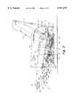
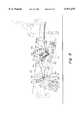
- FIG. 1is a side view of a three-way incliner chair constructed in accordance with the present invention and with the backrest, seat and footrest shown diagrammatically and with the incliner mechanism shown in detail and further, with the chair shown in the upright position;
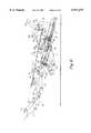
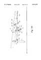
- FIGS. 2 and 3are views similar to FIG. 1 but respectively showing the chair in the intermediate and fully reclined positions;
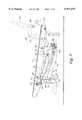
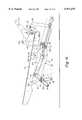
- FIGS. 4-6are enlarged side views of the mechanism shown in FIGS. 1-3 and with the mechanism in the upright, intermediate (TV) and fully reclined positions, respectively;
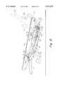
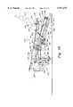
- FIG. 7is a fragmentary side view of the mechanism shown in FIGS. 1-6 and particularly showing the footrest drive assembly in full lines while other parts of the mechanism are shown in broken lines, and with the mechanism in the footrest in a retracted position;
- FIG. 8is a view similar to FIG. 7 but with the mechanism in the intermediate position and with the footrest drive assembly extended;
- FIG. 9is a side view of the mechanism similar to FIG. 7 and showing the footrest drive assembly retracted, and further showing the operation of the lock and cable release to retain the chair and mechanism in the upright position;
- FIG. 9Ais a fragmentary view of the mechanism similar to FIG. 9 but showing the lock and cable in the released position;
- FIG. 10is a side view of the mechanism in the intermediate or TV position highlighting the front linkage which carries the seat forward to the reclined position;
- FIG. 11is a view similar to FIG. 10 but with the mechanism in the fully reclined position;
- FIG. 12is a side view of another embodiment of the three-way incliner chair constructed in accordance with the present invention and with the backrest, seat and footrest shown diagrammatically and with the incliner mechanism shown in detail and further with the chair in the upright position.
- FIGS. 13 and 14are views similar to FIG. 12, but respectively showing the chair in the intermediate and fully reclined positions;
- FIGS. 15-17are enlarged side views of the mechanism shown in FIGS. 12-14 and with the mechanism in the upright, intermediate (TV) and fully reclined positions, respectively;
- FIG. 18is a fragmentary side view of the mechanism shown in FIGS. 12-17 and particularly featuring the footrest drive assembly and with the mechanism in the footrest retracted position;
- FIG. 19is a view similar to FIG. 18 but with the mechanism in the intermediate position and with the footrest drive assembly extended;
- FIG. 20is a side view of the mechanism in the upright position and highlighting the operation of the mechanism lock and cable release.
- the incliner chair shown on the drawingincludes a seat 10, backrest 12, and footrest 14, all collectively mounted on a frame 16 having side rails 18 connected together by cross rails 19.
- the seat, backrest and footrestare all supported on a recliner mechanism 20 shown in detail in the drawings.
- the mechanism 20enables the chair to move from the upright position shown in FIG. 1 to the intermediate or TV position shown in FIG. 2 and the fully reclined position shown in FIG. 3.
- the seat 10 and backrest 12move as a unit somewhat forwardly and downwardly with respect to the frame 16 (compare FIGS.
- the seat 10moves forward essentially in the plane it occupied in the TV position while the backrest tilts rearwardly with respect to the seat (compare FIGS. 2 and 3).
- the footrest 14elevates from a stored position beneath the seat when the chair is upright to an extended position beyond the front edge 22 of the seat when the chair moves from the upright to the TV position. The relative positions of the seat 10 and footrest 14 do not change as the chair continues to the fully reclined position.
- the mechanism 20is carried by a mounting link 30 which is secured in the inner surface of the side panel 18 of the frame 16.
- the mounting link 30made of steel (as are all the other elements of the mechanism) is bolted to the side panel 18.
- the mounting link 30carries a track 32 on its inner face defined in part by an angle member 34 riveted to the mounting link and a flange 36 formed as an integral part of the link 30.
- the track 32is upwardly and forwardly inclined with respect to the chair and carries a roller 38 which may move from the rearward most position shown in FIGS. 1 and 4, in a forward direction up the track to the extreme forward position shown in FIGS. 3 and 6.
- the roller 38in turn carries a trolley 46 pivotally mounted on the shaft 42 of the roller 38.
- the front end 46a of the trolley 46is supported on the fixed mounting link 30 by lower and upper travel links 43 and 45 as clearly shown in FIGS. 5 and 11. Specifically, pivot 48 joins the lower end of lower travel link 43 to the mounting link 30 and pivot 49 joins the upper end of the lower travel link 43 to the mid-portion of upper travel link 45. The lower end of the upper travel link 45 in turn is connected to the front end 46a of the trolley by pivot 51.
- a crank-shaped rear pivot link 40is pivotally connected first one end 40a by pivot 41 to the rear end 46b of the trolley 46, and the elbow 40b of the pivot link 40 is connected by pivot 56 to seat mounting bracket 54.
- a front pivot link 44is pivotally mounted adjacent the front end 46a of the trolley 46 at pivot 49. The opposite end of front pivot link 44 is pivotally connected at pivot 52 to the seat mounting bracket 54. The front pivot link 44 and the rear pivot link 40 together support the seat mounting bracket.
- the footrest 14is carried by a lazy tong linkage 70 made up of front and rear footrest swing links 72 and 74 each pivotally mounted at one end on the front end 76 of the seat mounting bracket 54 at 78 and 80, respectively, as best shown in FIGS. 5 and 6.
- the swing links 72 and 74are pivotally connected at their other ends to the ends of links 82 and 84 at pivots 86 and 88.
- the link 82in turn is connected at its other end to the footrest mounting bracket 90.
- the other end of link 84is connected to a pair of folding links 92 and 94.
- the link 94in turn is also connected to the footrest mounting bracket 90.
- the links 82 and 92are interconnected by pivot 96 intermediate their ends, and the front swing link 72 and the link 84 are connected intermediate their ends by pivot 98.
- the lazy tong linkageacts as a pantograph to move the footrest from a retracted position beneath the seat (FIGS. 1 and 4) to an extended position generally in the plane of the seat and forward of the front portion 22 thereof.
- footrest drive link 116is pivotally connected at its front end 115 by pivot 117 to the rear footrest swing link 74 and at its rear end 118 to the end 119 of the rear pivot link 40.
- the manner in which the footrest drive link functions to elevate the footrestis described in detail below in the description of the operation of the mechanism.
- the seat mounting bracket 54Adjacent its back end, the seat mounting bracket 54 carries a generally horse shoe shaped bracket 130 which is riveted to and moves with the seat mounting bracket 54.
- the bracket 130at its upper end by means of pivot 132 pivotally supports the backrest mounting link 134 on which the backrest 12 with its frame 13 is attached.
- the rear corner 135 of the backrest mounting link 134is pivotally connected at 136 to the top end of the back drive link 138 that in turn is connected at its lower end by pivot 140 to one end of the bellcrank 50.
- a linkage locking assembly 159 for retaining the mechanism 20 and thus the entire chair assembly in the upright positionis shown in FIGS. 9 and 9A.
- the assembly 159is pivotally connected to the seat mounting bracket 54 as described below.
- the locking assemblyincludes a lock link 162 connected at its front end 163 to the rear footrest swing link 74 at pivot 166.
- the other end of the footrest lock link 162is connected by pivot 172 to a bracket 168 in turn mounted on the square cross tube 170.
- the bracket 168is pivotally supported at its end opposite the square cross tube by pivot 169 on the seat mounting bracket 54.
- the footrest lock link 162 and bracket 168serve as an over center latch. When the two are in the position shown in FIG.
- the locking linkagealso includes a crank actuator 182 pivotally supported on the seat bracket 54 by pivot 184.
- the lower arm 183 of the actuator 182is connected to a manually operated cable 180 which, when actuated, pulls the arm 183 rearwardly so as to rotate the crank actuator counterclockwise.
- the other arm 185 of the actuator 182by means of a finger 187 carried by it, pushes the rear end of the footrest lock link 162 downwardly, which in turn causes the bracket 168 to turn clockwise about its pivot 169 and move the axis of the spring 171 to the other side of the pivot 169 (see FIG. 9A).
- This actionreleases the locking linkage and pushes the footrest lock link 162 in a forward direction and pivots the rear footrest swing link 74 in a clockwise direction to elevate the footrest.
- the chairWith the chair in the upright position of FIG. 1, the chair may be moved to the TV position by the occupant pulling on the cable 180 so as to cause the spring 171 of the lock assembly 159 to pass over center and release the mechanism from the locked position.
- a cable actuator 180ais mounted on a frame within easy reach of the person seated in the chair. When this occurs, the weight of the chair occupant causes the rear pivot link 40 to rotate counterclockwise from the position of FIGS. 1, 4 and 9 to the position of FIGS. 2, 5 and 10. That action moves the footrest drive link 116 rearwardly (compare FIGS.
- the seat mounting bracket 54moves forwardly and downwardly somewhat with respect to the mounting link 30 as rear and front pivot links 40 and 44 pivot counterclockwise on trolley 46 as viewed in the drawings.
- the forward travel of the seat mounting bracketis limited by the stop 82a on footrest link 82 engaging the lower edge of footrest link 84 as shown in FIGS. 2 and 5. In that fashion, the mechanism achieves the TV position for the seat.
- the backrest 12 during the transition from upright to TV positionremains fixed with respect to the seat 10.
- the upper travel link 45 during that operationis pushed forward at its lower end by the trolley 46 which in turn causes the lower travel link 43 to rotate counterclockwise (see FIGS. 5, 6, 10 and 11).
- the top end of the upper travel linkis limited to vertical movement only by the front control link 190.
- the upper travel link 45rotates clockwise and the lower travel link 43 rotates counterclockwise, the lower end of the upper travel link, as well as the front end of the trolley, move forwardly and upwardly in a straight line. This motion is made possible by the roller 38 which rolls to the front of track 32. So long as pressure is exerted against the backrest 12 by the occupant of the chair, the chair will remain in the fully reclined position.
- the chair occupantrelieves the pressure on the backrest, and the occupant's weight causes the seat and backrest to return to the TV position.
- downward pressure on the footrest 14causes the lazy tong linkage 70 to collapse and the rear pivot link 40 to pivot in a clockwise direction about its pivot 41 on trolley 46, which in turn causes the front pivot link 44 also to pivot clockwise and the seat to move to its upright and rearward most position.
- FIGS. 12-20utilizes a mechanism that bears many similarities to the mechanism of the preferred embodiment of FIGS. 1-11. Both utilize a combination of track and roller together with a linkage assembly to enable the chair to move between upright, TV and fully reclined positions. While the operation of the chairs is similar to one another, the two mechanisms are different from one another and each embodiment is separately described in detail.
- the incliner chair of the second embodimentincludes a seat 210, backrest 212, and footrest 214, all collectively mounted on a frame 216 having side rails 218 connected together by cross rails 219.
- the seat, backrest and footrestare all supported on a mechanism 220 shown in detail in the drawings.
- the mechanism 220enables the chair to move from the upright position shown in FIG. 12 to the intermediate or TV position shown in FIG. 13 and the fully reclined position shown in FIG. 14.
- the seat 210 and backrest 212move as a unit forwardly and downwardly with respect to the frame 216, and when the chair moves from the TV to the fully reclined position, the seat 210 moves forward essentially in the plane it occupied in the TV position while the backrest tilts rearwardly with respect to the seat.
- the footrest 214rises from a stored position beneath the seat when the chair is upright to an extended position beyond the front edge 222 of the seat when the chair moves from the upright to the TV position.
- the relative positions of the seat 210 and footrest 214do not change as the chair continues to the fully reclined position.
- the mechanism 220is carried by a mounting link 230 which is secured to the inner surface of the side panel 218 of the frame 216.
- the mounting link 230is made of steel, as are all the other elements of the mechanism, and is bolted to the side panel 218.
- the mounting link 230carries a track 232 on its inner face defined in part by an angle member 234 riveted to the mounting link and by a flange 236 formed as an integral part of the link 230.
- the track 232is upwardly and forwardly inclined with respect to the chair and carries a roller 238 which may move from the rearward most position shown in FIGS. 12 and 15, in a forward direction up the track to the extreme forward position shown in FIGS. 14 and 17.
- the roller 238in turn carries a rear pivot link 240 pivotally mounted on the shaft 242 of the roller.
- a front pivot link 244is pivotally mounted on the front lower end 246 of the mounting link 230 at pivot 248.
- the opposite end of front pivot link 244is pivotally connected at pivot 252 to the front lift link 250.
- the front lift link 250 and the rear pivot link 240together support the seat mounting bracket 254.
- the rear pivot link 240 which is crank-shapedis connected to the rear portion of the seat mounting bracket 254 at pivot 256 while the front lift link 250 which is also crank-shaped is connected to the seat mounting bracket at pivot 258 located at the elbow 260 of the front lift link (see FIGS. 16 and 17).
- the footrest 214is carried by a lazy tong linkage 270 that is essentially the same as the lazy tong linkage 70 of the first embodiment. It is made up of front and rear footrest swing links 272 and 274 both pivotally mounted on the front end 276 of the seat mounting bracket 254 at 278 and 280, respectively.
- the swing links 272 and 274are in turn pivotally connected at their ends to links 282 and 284 at pivots 286 and 288.
- the link 282in turn is connected at its other end to the footrest mounting bracket 290.
- the other end of link 284is connected to a pair of folding links 292 and 294.
- the link 294in turn is also connected to the footrest mounting bracket 290.
- the links 282 and 292are interconnected by pivot 296 intermediate their ends, and the front swing link 272 and the link 284 are connected intermediate their ends by pivot 298.
- the lazy tong linkageacts as a pantograph to move the footrest from a retracted position beneath the seat (FIGS. 12 and 15) to an extended position generally in the plane of the seat and forward of the front portion 222 thereof.
- a bell crank 310is pivotally mounted at one end on the seat mounting bracket 254 at 312, and the other end of the crank is pivotally connected at 314 to the footrest drive link 316 which in turn is pivotally connected at its front end 315 by pivot 317 to the rear footrest swing link 274 as is most clearly shown in FIGS. 17-19.
- the bell crank 310is connected to the front control link 318 at pivot 320.
- the other end of the front control link 318is pivotally connected at 322 to the front pivot link 244.
- the seat mounting bracket 254Adjacent its back end, the seat mounting bracket 254 carries a generally triangular-shaped shaped fixed bracket 330 which is riveted to and moves with the seat mounting bracket (see FIGS. 15-17).
- the bracket 330at its upper end by means of pivot 332 pivotally supports the backrest mounting link 334 which in turn carries the backrest 212 with its frame (not shown).
- the lower end of the backrest mounting link 334is pivotally connected at 336 to the rear end of the back drive link 338 in turn connected at its front end by pivot 340 to one end of the front lift link 250.
- a pivot 352 located at the elbow 353 of the rear pivot link 240joins the rear pivot link to a rear control link 350.
- the forward end of the rear control link 350is connected at pivot 315 to the midsection of footrest drive link 316 (see FIG. 19).
- the footrest drive link 316 and rear control link 350form continuations of each other although their angular relationship to one another varies slightly as the mechanism 220 moves from the upright to the TV and fully reclined positions.
- the rear control link 350controls the rotational motion of the rear pivot link 240 as is described more fully below in connection with the operation of the mechanism.
- a linkage locking assembly 359 for retaining the mechanism 220 and thus the entire chair assembly in the upright positionis shown in FIG. 20.
- the assembly 359is mounted on an extension bracket 360 fixed to the seat mounting bracket 254.
- the locking assembly 359also includes a lock link 362 connected to the rear footrest swing link 274 at pivot 366.
- the other end of the lock link 362is connected to a bracket 368 mounted on the square cross tube 370 in turn supported on the extension bracket 360.
- the connection between the footrest lock link 362 and the bracket 368is shown at 372.
- the footrest lock link 362 and bracket 368together form an over center latch. When the two are folded about the pivot 372 to the position shown in FIG.
- the center of the pivot 372lies over the center line defined by the square cross tube 370 and the pivot 366 joining the footrest lock link to the rear footrest swing link 274 so as to retain the footrest in the retracted position of FIGS. 12, 15 and 20 and prevents the mechanism 220 from moving.
- the pivot 372passes across the center line defined by pivot 366 and tube 370, the mechanism 220 is unlocked and may move from the upright position to the TV position of FIGS. 13 and 16 and further to the fully reclined position of FIGS. 14 and 17.
- the chairWith the chair in the upright position of FIG. 12, the chair may be moved to the TV position by the occupant pulling on the cable 380 by means of a handle, button or other well-known actuator suggested at 381 on the arm of the chair in easy reach of the chair occupant, so as to cause the pivot 372 of the lock assembly 359 to pass over center.
- the weight of the chair occupantcauses the front pivot link 244 to rotate counterclockwise from the position of FIGS. 12 and 15 to the position of FIGS. 13 and 16. That action moves the front control link 318 counterclockwise toward the vertical position and turns the crank 310 counterclockwise.
- That actionpushes the back drive link 338 in a forward direction which causes the front lift link 250 to turn in a counterclockwise direction around pivot 258, in turn causing the front pivot link 244 to pivot further in a counterclockwise direction and move seat mounting bracket 254 and the seat 10 in a straight path forwardly and upwardly from the positions of FIGS. 13 and 16 to that of FIGS. 14 and 17.
- the front control link 318 during that operationis pulled by the front pivot link 244 counterclockwise about the pivot 320 causing the seat to move in a straight path which also causes the roller 238 to travel to the front end of the track 232. So long as pressure is exerted against the backrest by the chair occupant, the chair will remain in the fully reclined position.
- the occupantrelieves the pressure on the backrest and the occupant's weight causes the seat and backrest to return to the TV position.
- downward pressure on the footrest 214causes the lazy tong linkage 270 to collapse and the crank 310 to pivot in a clockwise direction about its pivot 312 which in turn causes the front and rear pivot links 244 and 240 to pivot clockwise and the roller 238 to return to the rearward most position on track 232.
- each of the embodiments illustrated and describedprovides the advantages of both categories of reclining chair mechanisms found in the prior art.
- the mechanismis somewhat less expensive than a pure linkage capable of performing a similar function, and the mechanism increases the dimension tolerances allowed in the construction of the frame over what is required in a chair made of pure roller and track mechanism.
- the track and roller subassemblyprovides a very smooth and easy operation in the transition from the upright to the reclined positions.
Landscapes
- Health & Medical Sciences (AREA)
- Dentistry (AREA)
- General Health & Medical Sciences (AREA)
- Chairs For Special Purposes, Such As Reclining Chairs (AREA)
Abstract
Description
Claims (17)
Priority Applications (1)
| Application Number | Priority Date | Filing Date | Title |
|---|---|---|---|
| US08/985,014US5971475A (en) | 1996-12-05 | 1997-12-04 | Three-way incliner |
Applications Claiming Priority (2)
| Application Number | Priority Date | Filing Date | Title |
|---|---|---|---|
| US3211096P | 1996-12-05 | 1996-12-05 | |
| US08/985,014US5971475A (en) | 1996-12-05 | 1997-12-04 | Three-way incliner |
Publications (1)
| Publication Number | Publication Date |
|---|---|
| US5971475Atrue US5971475A (en) | 1999-10-26 |
Family
ID=26707984
Family Applications (1)
| Application Number | Title | Priority Date | Filing Date |
|---|---|---|---|
| US08/985,014Expired - LifetimeUS5971475A (en) | 1996-12-05 | 1997-12-04 | Three-way incliner |
Country Status (1)
| Country | Link |
|---|---|
| US (1) | US5971475A (en) |
Cited By (47)
| Publication number | Priority date | Publication date | Assignee | Title |
|---|---|---|---|---|
| EP1103208A1 (en)* | 1999-11-23 | 2001-05-30 | Ferdinand Lusch Gmbh & Co. Kg. | Recliner chair |
| US6494536B2 (en)* | 2000-01-14 | 2002-12-17 | B E Aerospace, Inc. | Passenger seat with variable length seat bottom |
| US20040051350A1 (en)* | 2001-09-05 | 2004-03-18 | Duncan Robert Barron | Method and apparatus for a three position wall-avoiding reclining chair |
| EP1438909A1 (en)* | 2002-12-24 | 2004-07-21 | Stema S.r.l. | Mechanism for reclining armchairs |
| US7040692B1 (en) | 2004-11-15 | 2006-05-09 | Jpd, Inc. | Support mechanism for rocker-recliner chair |
| US20070052273A1 (en)* | 2005-08-30 | 2007-03-08 | Aisin Seiki Kabushiki Kaisha | Seat apparatus |
| US20070132292A1 (en)* | 2003-10-30 | 2007-06-14 | Robco Designs Ltd | Adjustable reclining chair |
| EP1527714A4 (en)* | 2002-07-23 | 2007-08-29 | Okamura Corp | Chair |
| WO2009088711A1 (en)* | 2008-01-02 | 2009-07-16 | L & P Property Management Company | Zero-wall clearance linkage mechanism for a high-leg seating unit |
| US7850232B2 (en) | 2007-03-09 | 2010-12-14 | Ashley Furniture Industries, Inc. | Zero clearance recliner mechanism |
| CN102133006A (en)* | 2010-01-25 | 2011-07-27 | L&P产权管理公司 | Zero-wall-clearance linkage mechanism for a high-leg seating unit |
| US20120256468A1 (en)* | 2011-04-11 | 2012-10-11 | Benny Mack Owens | Flexible Pull Strap Recliner Mechanism Release System |
| US8651569B2 (en) | 2010-09-07 | 2014-02-18 | InkBed, Inc. | Apparatus for support during tattooing |
| US8882190B2 (en) | 2011-03-30 | 2014-11-11 | American Leather Operations, Llc | Reclining chair |
| US20140333099A1 (en)* | 2013-05-10 | 2014-11-13 | Hhc Changzhou Inc | Linkage mechanism and reclining chair having same |
| US20140375087A1 (en)* | 2013-06-21 | 2014-12-25 | Toyota Boshoku Kabushiki Kaisha | Seat back interlocking ottoman device and vehicle seat |
| US20150054316A1 (en)* | 2013-08-21 | 2015-02-26 | L & P Property Management Company | Reclining and ottoman-extending chair mechanism |
| US9084486B1 (en) | 2014-01-09 | 2015-07-21 | InkBed, Inc. | Tattoo stools and chairs and methods using the same |
| US20150230607A1 (en)* | 2012-08-17 | 2015-08-20 | Myung Su Jang | Sitting type shampoo chair |
| US9433294B2 (en) | 2013-08-21 | 2016-09-06 | L & P Property Management Company | Reclining and ottoman-extending chair mechanism |
| US20160270537A1 (en)* | 2015-03-17 | 2016-09-22 | La-Z-Boy Incorporated | Wall proximity furniture member reclining mechanism |
| US20180161223A1 (en)* | 2016-12-12 | 2018-06-14 | Ultra-Mek, Inc. | Power-assisted reclining lift chair with split seat |
| US10092106B2 (en) | 2015-07-14 | 2018-10-09 | La-Z-Boy Incorporated | Recliner and legrest mechanism for a furniture member |
| CN108698525A (en)* | 2016-03-10 | 2018-10-23 | 德鱼塔工业股份有限公司 | Armchair structure |
| CN108991793A (en)* | 2017-06-07 | 2018-12-14 | 舒尔股份公司 | Seat and outdoor furniture |
| USD846326S1 (en) | 2017-08-07 | 2019-04-23 | Shanghai Industries Group, Ltd. | Pull strap for a reclining seat |
| US10299597B1 (en)* | 2018-02-13 | 2019-05-28 | L&P Property Management Company | High-leg hidden ottoman recliner seating mechanism |
| US20190290004A1 (en)* | 2018-03-22 | 2019-09-26 | L&P Property Management Company | Low-profile, zero gravity, all-linkage seat mechanism with added back recline |
| US10506881B2 (en) | 2014-01-09 | 2019-12-17 | InkBed, Inc. | Stools, chairs, and methods using the same |
| US10524573B2 (en) | 2014-01-09 | 2020-01-07 | InkBed, Inc. | Stools, chairs, and methods using the same |
| US10524574B2 (en) | 2018-05-18 | 2020-01-07 | La-Z-Boy Incorporated | Furniture member with powered wall-proximity mechanism |
| US10524575B2 (en) | 2018-04-16 | 2020-01-07 | La-Z-Boy Incorporated | Furniture member with foldable pawl and ratchet assembly |
| US10537178B2 (en) | 2017-04-07 | 2020-01-21 | La-Z-Boy Incorporated | Furniture member having flexible seatback |
| US10568428B2 (en) | 2017-04-07 | 2020-02-25 | La-Z-Boy Incorporated | Furniture member having flexible seatback |
| US10709246B2 (en) | 2017-01-26 | 2020-07-14 | Ultra-Mek, Inc. | Reclining high-leg seating unit |
| US10779653B2 (en) | 2016-09-22 | 2020-09-22 | La-Z-Boy Incorporated | Furniture member having legrest mechanism |
| US10820708B2 (en) | 2018-05-18 | 2020-11-03 | La-Z-Boy Incorporated | Furniture member with wall-proximity mechanism and locking trigger |
| US11134778B2 (en) | 2019-05-09 | 2021-10-05 | La-Z-Boy Incorporated | Reclining chaise |
| US11197549B1 (en) | 2020-09-28 | 2021-12-14 | La-Z-Boy Incorporated | Wall-proximity furniture member having sync mechanism |
| US11278120B2 (en)* | 2018-01-12 | 2022-03-22 | L&P Property Management Company | Recliner seating mechanism with seat extension |
| WO2022232120A1 (en)* | 2021-04-28 | 2022-11-03 | L&P Property Management Company | Slim-profile, all-linkage, wall-proximity reclining mechanism allowing a wood-to-floor recliner seating unit |
| CN115721491A (en)* | 2021-09-01 | 2023-03-03 | 董明 | A bearing device that changes shape to meet the needs of human body posture changes |
| US20230103963A1 (en)* | 2021-10-01 | 2023-04-06 | Current Products Corp. | Seating system |
| US11707136B2 (en) | 2018-02-14 | 2023-07-25 | InkBed, Inc. | Stools and chairs with translatable armrests |
| US11779120B2 (en) | 2018-02-13 | 2023-10-10 | LCL Enterprises, Inc. | Chairs with adjustable back supports |
| WO2023212996A1 (en)* | 2022-05-06 | 2023-11-09 | 广东佳居家具有限公司 | Zero-gravity leisure chair driven by human body power |
| WO2025185524A1 (en)* | 2024-03-08 | 2025-09-12 | 锐迈科技股份有限公司 | Mechanical stretching device for liftable seat, and liftable seat |
Citations (9)
| Publication number | Priority date | Publication date | Assignee | Title |
|---|---|---|---|---|
| US3637255A (en)* | 1968-01-02 | 1972-01-25 | Dual Mfg & Eng | Mechanism for rocker/reclining chair and for reclining chair |
| US4195878A (en)* | 1977-10-25 | 1980-04-01 | Mohasco Corporation | Reclining chair |
| US4531778A (en)* | 1982-09-29 | 1985-07-30 | Parma Corporation | Recliner chair incorporating linkage and track systems |
| US4815788A (en)* | 1987-06-25 | 1989-03-28 | Super Sagless Corp. | Three-way incliner |
| US4904019A (en)* | 1987-10-01 | 1990-02-27 | Super Sagless Corporation | Three-way recliner |
| US5056862A (en)* | 1990-07-03 | 1991-10-15 | Action Industries, Inc. | Recessed lever actuator for recliner mechanism |
| US5072988A (en)* | 1987-06-09 | 1991-12-17 | Super Sagless Corporation | Wall proximity chair |
| US5147108A (en)* | 1990-10-18 | 1992-09-15 | La-Z-Boy Chair Company | Reclining sofa |
| US5419611A (en)* | 1992-10-09 | 1995-05-30 | Super Sagless Corporation | Footrest assembly for reclining chair |
- 1997
- 1997-12-04USUS08/985,014patent/US5971475A/ennot_activeExpired - Lifetime
Patent Citations (9)
| Publication number | Priority date | Publication date | Assignee | Title |
|---|---|---|---|---|
| US3637255A (en)* | 1968-01-02 | 1972-01-25 | Dual Mfg & Eng | Mechanism for rocker/reclining chair and for reclining chair |
| US4195878A (en)* | 1977-10-25 | 1980-04-01 | Mohasco Corporation | Reclining chair |
| US4531778A (en)* | 1982-09-29 | 1985-07-30 | Parma Corporation | Recliner chair incorporating linkage and track systems |
| US5072988A (en)* | 1987-06-09 | 1991-12-17 | Super Sagless Corporation | Wall proximity chair |
| US4815788A (en)* | 1987-06-25 | 1989-03-28 | Super Sagless Corp. | Three-way incliner |
| US4904019A (en)* | 1987-10-01 | 1990-02-27 | Super Sagless Corporation | Three-way recliner |
| US5056862A (en)* | 1990-07-03 | 1991-10-15 | Action Industries, Inc. | Recessed lever actuator for recliner mechanism |
| US5147108A (en)* | 1990-10-18 | 1992-09-15 | La-Z-Boy Chair Company | Reclining sofa |
| US5419611A (en)* | 1992-10-09 | 1995-05-30 | Super Sagless Corporation | Footrest assembly for reclining chair |
Cited By (90)
| Publication number | Priority date | Publication date | Assignee | Title |
|---|---|---|---|---|
| EP1103208A1 (en)* | 1999-11-23 | 2001-05-30 | Ferdinand Lusch Gmbh & Co. Kg. | Recliner chair |
| US6494536B2 (en)* | 2000-01-14 | 2002-12-17 | B E Aerospace, Inc. | Passenger seat with variable length seat bottom |
| US7261367B2 (en) | 2001-09-05 | 2007-08-28 | Robert Barron Duncan | Method and apparatus for a three position wall-avoiding reclining chair |
| US20040051350A1 (en)* | 2001-09-05 | 2004-03-18 | Duncan Robert Barron | Method and apparatus for a three position wall-avoiding reclining chair |
| EP1527714A4 (en)* | 2002-07-23 | 2007-08-29 | Okamura Corp | Chair |
| EP1438909A1 (en)* | 2002-12-24 | 2004-07-21 | Stema S.r.l. | Mechanism for reclining armchairs |
| US20070132292A1 (en)* | 2003-10-30 | 2007-06-14 | Robco Designs Ltd | Adjustable reclining chair |
| US7575279B2 (en)* | 2003-10-30 | 2009-08-18 | Robco Designs Ltd. | Adjustable reclining chair |
| US20060103179A1 (en)* | 2004-11-15 | 2006-05-18 | Pine James J | Support mechanism for rocker-recliner chair |
| US7040692B1 (en) | 2004-11-15 | 2006-05-09 | Jpd, Inc. | Support mechanism for rocker-recliner chair |
| US20070052273A1 (en)* | 2005-08-30 | 2007-03-08 | Aisin Seiki Kabushiki Kaisha | Seat apparatus |
| US7699399B2 (en)* | 2005-08-30 | 2010-04-20 | Aisin Seiki Kabushiki Kaisha | Seat apparatus |
| US7850232B2 (en) | 2007-03-09 | 2010-12-14 | Ashley Furniture Industries, Inc. | Zero clearance recliner mechanism |
| WO2009088711A1 (en)* | 2008-01-02 | 2009-07-16 | L & P Property Management Company | Zero-wall clearance linkage mechanism for a high-leg seating unit |
| CN101485522B (en)* | 2008-01-02 | 2013-01-30 | L&P产权管理公司 | Zero-wall clearance linkage mechanism for a high-leg seating unit |
| CN102133006A (en)* | 2010-01-25 | 2011-07-27 | L&P产权管理公司 | Zero-wall-clearance linkage mechanism for a high-leg seating unit |
| WO2011090828A1 (en)* | 2010-01-25 | 2011-07-28 | L & P Property Management Company | Zero-wall clearance linkage mechanism for high-leg seating unit |
| US20110181094A1 (en)* | 2010-01-25 | 2011-07-28 | L & P Property Management Company | Zero-Wall Clearance Linkage Mechanism for a High-Leg Seating Unit |
| CN102133006B (en)* | 2010-01-25 | 2015-10-21 | L&P产权管理公司 | For the Zero-wall clearance link gear of high-leg seating unit |
| US8419122B2 (en) | 2010-01-25 | 2013-04-16 | L & P Property Management Company | Zero-wall clearance linkage mechanism for a high-leg seating unit |
| US8651569B2 (en) | 2010-09-07 | 2014-02-18 | InkBed, Inc. | Apparatus for support during tattooing |
| US11246418B2 (en) | 2010-09-07 | 2022-02-15 | InkBed, Inc. | Apparatus for support during tattooing |
| US10264885B2 (en) | 2010-09-07 | 2019-04-23 | InkBed, Inc. | Apparatus for support during tattooing |
| US10638843B2 (en) | 2010-09-07 | 2020-05-05 | InkBed, Inc. | Apparatus for support during tattooing |
| US9375088B2 (en) | 2010-09-07 | 2016-06-28 | InkBed, Inc. | Apparatus for support during tattooing |
| US10966526B2 (en) | 2011-03-30 | 2021-04-06 | American Leather Operations, Llc | Reclining chair |
| US8882190B2 (en) | 2011-03-30 | 2014-11-11 | American Leather Operations, Llc | Reclining chair |
| US10251484B2 (en) | 2011-03-30 | 2019-04-09 | American Leather Operations, Llc | Reclining chair |
| US9504328B2 (en) | 2011-03-30 | 2016-11-29 | American Leather Operations, Llc | Reclining chair |
| USD738662S1 (en) | 2011-04-11 | 2015-09-15 | Shanghai Industries Group (Sig) | Pull strap for a recliner mechanism |
| US20120256468A1 (en)* | 2011-04-11 | 2012-10-11 | Benny Mack Owens | Flexible Pull Strap Recliner Mechanism Release System |
| US9332843B2 (en)* | 2012-08-17 | 2016-05-10 | Myung Su Jang | Sitting type shampoo chair |
| US20150230607A1 (en)* | 2012-08-17 | 2015-08-20 | Myung Su Jang | Sitting type shampoo chair |
| US20140333099A1 (en)* | 2013-05-10 | 2014-11-13 | Hhc Changzhou Inc | Linkage mechanism and reclining chair having same |
| US20140375087A1 (en)* | 2013-06-21 | 2014-12-25 | Toyota Boshoku Kabushiki Kaisha | Seat back interlocking ottoman device and vehicle seat |
| US9873356B2 (en)* | 2013-06-21 | 2018-01-23 | Toyota Boshoku Kabushiki Kaisha | Seat back interlocking ottoman device and vehicle seat |
| US9433294B2 (en) | 2013-08-21 | 2016-09-06 | L & P Property Management Company | Reclining and ottoman-extending chair mechanism |
| US9398810B2 (en)* | 2013-08-21 | 2016-07-26 | L & P Property Management Company | Reclining and ottoman-extending chair mechanism |
| US20150054316A1 (en)* | 2013-08-21 | 2015-02-26 | L & P Property Management Company | Reclining and ottoman-extending chair mechanism |
| US10123620B2 (en) | 2013-08-21 | 2018-11-13 | L&P Property Management Company | Reclining and ottoman-extending chair mechanism |
| US10238213B2 (en) | 2014-01-09 | 2019-03-26 | InkBed, Inc. | Stools, chairs, and methods using the same |
| US10506881B2 (en) | 2014-01-09 | 2019-12-17 | InkBed, Inc. | Stools, chairs, and methods using the same |
| US12239227B2 (en) | 2014-01-09 | 2025-03-04 | InkBed, Inc. | Stools, chairs, and methods using the same |
| US11805904B2 (en) | 2014-01-09 | 2023-11-07 | InkBed, Inc. | Stools, chairs, and methods using the same |
| US10524573B2 (en) | 2014-01-09 | 2020-01-07 | InkBed, Inc. | Stools, chairs, and methods using the same |
| US9814313B2 (en) | 2014-01-09 | 2017-11-14 | InkBed, Inc. | Stools, chairs, and methods using the same |
| US9084486B1 (en) | 2014-01-09 | 2015-07-21 | InkBed, Inc. | Tattoo stools and chairs and methods using the same |
| US9451831B2 (en) | 2014-01-09 | 2016-09-27 | InkBed, Inc. | Tattoo stool or a chair |
| US10959523B2 (en) | 2014-01-09 | 2021-03-30 | InkBed, Inc. | Stools, chairs, and methods using the same |
| US20160270537A1 (en)* | 2015-03-17 | 2016-09-22 | La-Z-Boy Incorporated | Wall proximity furniture member reclining mechanism |
| US9655450B2 (en)* | 2015-03-17 | 2017-05-23 | La-Z-Boy Incorporated | Wall proximity furniture member reclining mechanism |
| US10512332B2 (en) | 2015-07-14 | 2019-12-24 | La-Z-Boy Incorporated | Recliner and legrest mechanism for a furniture member |
| US10092106B2 (en) | 2015-07-14 | 2018-10-09 | La-Z-Boy Incorporated | Recliner and legrest mechanism for a furniture member |
| CN108698525B (en)* | 2016-03-10 | 2021-04-27 | 德鱼塔工业股份有限公司 | seat structure |
| CN108698525A (en)* | 2016-03-10 | 2018-10-23 | 德鱼塔工业股份有限公司 | Armchair structure |
| US10779653B2 (en) | 2016-09-22 | 2020-09-22 | La-Z-Boy Incorporated | Furniture member having legrest mechanism |
| US10485719B2 (en)* | 2016-12-12 | 2019-11-26 | Ultra-Mek, Inc. | Power-assisted reclining lift chair with split seat |
| US20180161223A1 (en)* | 2016-12-12 | 2018-06-14 | Ultra-Mek, Inc. | Power-assisted reclining lift chair with split seat |
| US11241094B2 (en) | 2017-01-26 | 2022-02-08 | Ultra-Mek, Inc. | Reclining high-leg seating unit |
| US10709246B2 (en) | 2017-01-26 | 2020-07-14 | Ultra-Mek, Inc. | Reclining high-leg seating unit |
| US10537178B2 (en) | 2017-04-07 | 2020-01-21 | La-Z-Boy Incorporated | Furniture member having flexible seatback |
| US10750870B2 (en) | 2017-04-07 | 2020-08-25 | La-Z-Boy Incorporated | Furniture member having flexible seatback |
| US10568428B2 (en) | 2017-04-07 | 2020-02-25 | La-Z-Boy Incorporated | Furniture member having flexible seatback |
| CN108991793B (en)* | 2017-06-07 | 2022-11-08 | 舒尔股份公司 | Seat and leisure furniture |
| CN108991793A (en)* | 2017-06-07 | 2018-12-14 | 舒尔股份公司 | Seat and outdoor furniture |
| US10441081B2 (en)* | 2017-06-07 | 2019-10-15 | Ciar S.P.A. | Seating and lounging furniture |
| USD846326S1 (en) | 2017-08-07 | 2019-04-23 | Shanghai Industries Group, Ltd. | Pull strap for a reclining seat |
| USD848774S1 (en) | 2017-08-07 | 2019-05-21 | Shanghai Industries Group, Ltd. | Pull strap for reclining seat |
| US11278120B2 (en)* | 2018-01-12 | 2022-03-22 | L&P Property Management Company | Recliner seating mechanism with seat extension |
| US11779120B2 (en) | 2018-02-13 | 2023-10-10 | LCL Enterprises, Inc. | Chairs with adjustable back supports |
| US10299597B1 (en)* | 2018-02-13 | 2019-05-28 | L&P Property Management Company | High-leg hidden ottoman recliner seating mechanism |
| US12114787B2 (en) | 2018-02-13 | 2024-10-15 | LCL Enterprises, Inc. | Chairs with adjustable back supports |
| US12207738B2 (en) | 2018-02-14 | 2025-01-28 | InkBed, Inc. | Stools and chairs with translatable armrests |
| US11707136B2 (en) | 2018-02-14 | 2023-07-25 | InkBed, Inc. | Stools and chairs with translatable armrests |
| US20190290004A1 (en)* | 2018-03-22 | 2019-09-26 | L&P Property Management Company | Low-profile, zero gravity, all-linkage seat mechanism with added back recline |
| US10512333B2 (en)* | 2018-03-22 | 2019-12-24 | L&P Property Management Company | Low-profile, zero gravity, all-linkage seat mechanism with added back recline |
| US10524575B2 (en) | 2018-04-16 | 2020-01-07 | La-Z-Boy Incorporated | Furniture member with foldable pawl and ratchet assembly |
| US10820708B2 (en) | 2018-05-18 | 2020-11-03 | La-Z-Boy Incorporated | Furniture member with wall-proximity mechanism and locking trigger |
| US10524574B2 (en) | 2018-05-18 | 2020-01-07 | La-Z-Boy Incorporated | Furniture member with powered wall-proximity mechanism |
| US11134778B2 (en) | 2019-05-09 | 2021-10-05 | La-Z-Boy Incorporated | Reclining chaise |
| US11622629B2 (en) | 2020-09-28 | 2023-04-11 | La-Z-Boy Incorporated | Wall-proximity furniture member having sync mechanism |
| US11197549B1 (en) | 2020-09-28 | 2021-12-14 | La-Z-Boy Incorporated | Wall-proximity furniture member having sync mechanism |
| US11766124B2 (en) | 2021-04-28 | 2023-09-26 | L&P Property Management Company | Slim-profile, all-linkage, wall-proximity reclining mechanism allowing a wood-to-floor recliner seating unit |
| WO2022232120A1 (en)* | 2021-04-28 | 2022-11-03 | L&P Property Management Company | Slim-profile, all-linkage, wall-proximity reclining mechanism allowing a wood-to-floor recliner seating unit |
| US12232618B2 (en) | 2021-04-28 | 2025-02-25 | L&Pproperty Management Company | Slim-profile, all-linkage, wall-proximity reclining mechanism allowing a wood-to-floor recliner seating unit |
| CN115721491A (en)* | 2021-09-01 | 2023-03-03 | 董明 | A bearing device that changes shape to meet the needs of human body posture changes |
| US20230103963A1 (en)* | 2021-10-01 | 2023-04-06 | Current Products Corp. | Seating system |
| US12022959B2 (en)* | 2021-10-01 | 2024-07-02 | Current Products Corp. | Seating system |
| WO2023212996A1 (en)* | 2022-05-06 | 2023-11-09 | 广东佳居家具有限公司 | Zero-gravity leisure chair driven by human body power |
| WO2025185524A1 (en)* | 2024-03-08 | 2025-09-12 | 锐迈科技股份有限公司 | Mechanical stretching device for liftable seat, and liftable seat |
Similar Documents
| Publication | Publication Date | Title |
|---|---|---|
| US5971475A (en) | Three-way incliner | |
| US5823614A (en) | Three-way reclining furniture item | |
| EP1173083B1 (en) | Footrest mechanism and furniture item | |
| US5072988A (en) | Wall proximity chair | |
| CA1162836A (en) | Reclining chair with improved actuation | |
| US4904019A (en) | Three-way recliner | |
| US5129701A (en) | Double-shift carriage mechanism for full recline incliner chair | |
| EP2028973B1 (en) | Linkage mechanism for a recliner chair | |
| US5147108A (en) | Reclining sofa | |
| WO1997047219A9 (en) | Three-way reclining furniture item | |
| US4878710A (en) | Wall proximity chair | |
| US4291913A (en) | Manually-operated reclining chairs | |
| US4815788A (en) | Three-way incliner | |
| US20010035668A1 (en) | Power actuated reclining chair with wall-hugger function | |
| US7594694B2 (en) | Sleep over recliner chair | |
| GB1594388A (en) | Reclining chair | |
| US5374101A (en) | Three-way reclining chair | |
| NZ239583A (en) | Chair having interconnected seat tilting and leg rest movement | |
| JPH0887B2 (en) | Reclining chair | |
| JPH02111311A (en) | Mechanism of chair | |
| US5186518A (en) | Carriage mechanism for a glider/three-way recliner chair having rear drive link and rear ottoman link | |
| US5054850A (en) | Shiftable carriage mechanism for incliner chair | |
| US4826243A (en) | Recliner chairs | |
| US6637813B2 (en) | Reclining mechanism and furniture item having pusher mechanism | |
| EP1050248A2 (en) | Power actuated reclining chair with wall-hugger function |
Legal Events
| Date | Code | Title | Description |
|---|---|---|---|
| AS | Assignment | Owner name:OMEGA MOTION LLC, MISSISSIPPI Free format text:ASSIGNMENT OF ASSIGNORS INTEREST;ASSIGNORS:LAWSON, GREGORY M.;LAKE, STEPHEN R.;REEL/FRAME:009144/0565 Effective date:19980423 | |
| STCF | Information on status: patent grant | Free format text:PATENTED CASE | |
| FEPP | Fee payment procedure | Free format text:PAYOR NUMBER ASSIGNED (ORIGINAL EVENT CODE: ASPN); ENTITY STATUS OF PATENT OWNER: LARGE ENTITY | |
| AS | Assignment | Owner name:L & P PROPERTY MANAGEMENT COMPANY, CALIFORNIA Free format text:ASSIGNMENT OF ASSIGNORS INTEREST;ASSIGNOR:OMEGA MOTION, LLC;REEL/FRAME:010776/0631 Effective date:19991229 Owner name:L & P PROPERTY MANAGEMENT COMPANY, A DELAWARE CORP Free format text:ASSIGNMENT OF ASSIGNORS INTEREST;ASSIGNOR:OMEGA MOTION, LLC;REEL/FRAME:010776/0631 Effective date:19991229 | |
| FEPP | Fee payment procedure | Free format text:PAYOR NUMBER ASSIGNED (ORIGINAL EVENT CODE: ASPN); ENTITY STATUS OF PATENT OWNER: LARGE ENTITY Free format text:PAYER NUMBER DE-ASSIGNED (ORIGINAL EVENT CODE: RMPN); ENTITY STATUS OF PATENT OWNER: LARGE ENTITY | |
| FEPP | Fee payment procedure | Free format text:PAYER NUMBER DE-ASSIGNED (ORIGINAL EVENT CODE: RMPN); ENTITY STATUS OF PATENT OWNER: LARGE ENTITY Free format text:PAYOR NUMBER ASSIGNED (ORIGINAL EVENT CODE: ASPN); ENTITY STATUS OF PATENT OWNER: LARGE ENTITY | |
| FEPP | Fee payment procedure | Free format text:PAYOR NUMBER ASSIGNED (ORIGINAL EVENT CODE: ASPN); ENTITY STATUS OF PATENT OWNER: LARGE ENTITY Free format text:PAT HOLDER NO LONGER CLAIMS SMALL ENTITY STATUS, ENTITY STATUS SET TO UNDISCOUNTED (ORIGINAL EVENT CODE: STOL); ENTITY STATUS OF PATENT OWNER: LARGE ENTITY Free format text:PAYER NUMBER DE-ASSIGNED (ORIGINAL EVENT CODE: RMPN); ENTITY STATUS OF PATENT OWNER: LARGE ENTITY | |
| REFU | Refund | Free format text:REFUND - SURCHARGE, PETITION TO ACCEPT PYMT AFTER EXP, UNINTENTIONAL (ORIGINAL EVENT CODE: R2551); ENTITY STATUS OF PATENT OWNER: LARGE ENTITY | |
| FPAY | Fee payment | Year of fee payment:4 | |
| FEPP | Fee payment procedure | Free format text:PAYOR NUMBER ASSIGNED (ORIGINAL EVENT CODE: ASPN); ENTITY STATUS OF PATENT OWNER: LARGE ENTITY Free format text:PAYER NUMBER DE-ASSIGNED (ORIGINAL EVENT CODE: RMPN); ENTITY STATUS OF PATENT OWNER: LARGE ENTITY | |
| REMI | Maintenance fee reminder mailed | ||
| FPAY | Fee payment | Year of fee payment:8 | |
| SULP | Surcharge for late payment | Year of fee payment:7 | |
| FEPP | Fee payment procedure | Free format text:PAYER NUMBER DE-ASSIGNED (ORIGINAL EVENT CODE: RMPN); ENTITY STATUS OF PATENT OWNER: LARGE ENTITY Free format text:PAYOR NUMBER ASSIGNED (ORIGINAL EVENT CODE: ASPN); ENTITY STATUS OF PATENT OWNER: LARGE ENTITY | |
| FPAY | Fee payment | Year of fee payment:12 |