US5971267A - Mailbox stand - Google Patents
Mailbox standDownload PDFInfo
- Publication number
- US5971267A US5971267AUS09/181,237US18123798AUS5971267AUS 5971267 AUS5971267 AUS 5971267AUS 18123798 AUS18123798 AUS 18123798AUS 5971267 AUS5971267 AUS 5971267A
- Authority
- US
- United States
- Prior art keywords
- post
- shelf
- mailbox
- holes
- stand according
- Prior art date
- Legal status (The legal status is an assumption and is not a legal conclusion. Google has not performed a legal analysis and makes no representation as to the accuracy of the status listed.)
- Expired - Fee Related
Links
- 230000000295complement effectEffects0.000claimsabstractdescription6
- 238000003780insertionMethods0.000claimsabstract3
- 230000037431insertionEffects0.000claimsabstract3
- 238000000465mouldingMethods0.000claimsdescription3
- 230000004075alterationEffects0.000description1
- 230000004048modificationEffects0.000description1
- 238000012986modificationMethods0.000description1
- 239000004576sandSubstances0.000description1
Images


Classifications
- A—HUMAN NECESSITIES
- A47—FURNITURE; DOMESTIC ARTICLES OR APPLIANCES; COFFEE MILLS; SPICE MILLS; SUCTION CLEANERS IN GENERAL
- A47G—HOUSEHOLD OR TABLE EQUIPMENT
- A47G29/00—Supports, holders, or containers for household use, not provided for in groups A47G1/00-A47G27/00 or A47G33/00
- A47G29/12—Mail or newspaper receptacles, e.g. letter-boxes; Openings in doors or the like for delivering mail or newspapers
- A47G29/1209—Rural letter-boxes
- A47G29/1216—Supports
Definitions
- This inventionis in the field of vertical posts. More specifically, this invention is used to support a mailbox.
- Mail boxesutilize vertical stands having a bottom end in the ground and secured thereto by sand, stones or concrete. Mounted to the vertical stand is a horizontally extending shelf upon which the standard rural mailbox is mounted.
- the vertical standtakes a variety of configurations; however, most of the configurations include both a vertical stand and a horizontally extending shelf.
- the mailbox standis mounted adjacent the road and is often subjected to whether, vehicle impacts and vandalism. Replacement is time consuming and a bother since, in many cases, the stand is mounted to the ground.
- a mailbox standwhich is configured so as to provide a sturdy and durable structure, as well as aesthetically pleasing appearance.
- the mailboxis also easy to assemble and install.
- the present inventionprovides a mailbox stand comprising a vertically extending post having a grooved exterior, a top end and a bottom end in contact with the ground.
- the mailbox standalso comprises a horizontally extending shelf slidably mounted onto the vertically extending post.
- the horizontally extending shelffurther comprises a proximal end, two exterior sides, a cover, a bottom side and a top side which defines an aperture near the proximal end which extends through the bottom side for engaging the vertically extending post.
- a post capOn top of the vertically extending post is a post cap removably coupled to the top end.
- Below the horizontally extending shelfis a support structure which is coupled to the shelf and in communication with the grooved exterior of the vertically extending post.
- FIG. 1is a side elevational view of the mailbox stand according to this invention.
- FIG. 2is a top plan view of the shelf portion of the mailbox stand as seen in FIG. 1.
- FIG. 3is a cross-sectional view of aperture along lines B--B and C--C as seen in FIG. 2.
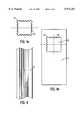
- FIG. 4is a side elevational view of the post as seen in FIG. 1.
- FIG. 4ais a cross-sectional view of the post of FIG. 1 along line C--C.
- FIG. 4bis a preferred embodiment of the aperture having a shape complimentary to the post.
- FIG. 5is a top elevational view of the cover with mounting brackets.
- FIG. 5ais a front elevational view of the cover.
- FIG. 5bis a side elevational view of the cover.
- FIG. 6is a perspective view of the mounting brackets for mounting the mailbox onto the shelf.
- a mailbox stand 1including a vertically extending post 3 and a horizontally extending shelf 11 slidably mounted onto the vertically extending post 3 and secured to the post 3 by mounting brackets (not shown).
- the horizontally extending shelf 11defines an aperture 19 near the proximal end 13 of the shelf 11 by which the shelf 11 is mounted.
- the top end 7 of the vertically extending post 3can receive a removable post cap 20.
- Post cap 20can have any desired ornamentation, including a rounded extension 21 and/or a return ring 29.
- the bottom end of the post 3is in communication with the ground 9.
- the top side 17 of the horizontally extending shelf 11comprises a set of holes 37 for mounting cover 60, further described in FIG. 5, onto shelf 11.
- the cover 60is mounted with fasteners extending through holes in the cover 60 (not shown) which are complimentary to holes 37.
- a support structure 23which comprises decorative molding 25.
- Support structure 23contacts grooved exterior 5 of the vertically extending post 3 for rigidity.
- the support structure 23comprises a lower structure 23a which is a series of concave 22 and convex 24 impressions.
- the lower structure 23ahas a height (X) along grooved exterior 5 of the vertically extending post 3.
- the structure 23atapers to a height (A), which is less than height (X), at an opposite end adjacent the connection to the bottom side 15 of the horizontally extending shelf 11.
- the support structurealso comprises an upper structure 23b of decorative molding 25 which extends approximately the length of the horizontally extending shelf 11.
- the support structure 23is designed to provide support for the weight of the horizontally extending shelf 11 and the mailbox atop the shelf 11.
- a cross-sectional view of the horizontally extending shelf 11 at the aperture 19 along line B--B and line C--Cshows a set 41 and a set 43 of holes at the front wall 45 and back wall 47 of the aperture 19, respectively.
- These sets of holes 41 and 43align with a set of holes 51 on the vertically extending post 3 as seen in FIG. 4 at the point where the horizontally extending shelf 11 is to be mounted onto the vertically extending post 3.
- the mountingis accomplished by a fastening means, preferably bolts or screws, which pass through the sets of holes at the front wall 45, the back wall 47 and the post 3.
- aperture 19is complementary to the shape of the vertically extending post 3.
- a cross-sectional view along line C--C (FIG. 1) of the vertical post 3shows the rounded corners 53 and scalloped faces 54 formed by the grooved exterior 5 of the vertically extending post 3.
- aperture 19likewise comprises rounded corners 53' and scalloped faces 54' formed to complement the design of the vertically extending post, allowing for a smooth sliding fit of the shelf 11 onto the post 3.
- the aperture 19should be slightly larger than the post to allow such a fit.
- Post 3may come in any desirable pattern or shape. In any instance, the aperture 19 should be in a pattern or shape which is complementary to the shape of the post 3.
- cover 60is provided for accommodating a conventional mailbox of various sizes, the cover 60 also having an aperture 19' which is complimentary in shape and dimension to aperture 19.
- the cover 60further comprises a number of slots 62 running in a direction perpendicular to aperture 19, the slots comprising holes for receiving a fastener.
- the cover 60also comprises decorative features 70 consistent with shelf 11.
- Mounting brackets 64are utilized to secure a mailbox to the cover 60.
- the mounting bracket 64is preferably an "L" bracket comprising 3 openings on a bottom side 66 and one opening on an extended side 64.
- the bracketis attached by a fastener at a position on any one of slots 62 of cover 60 to accommodate the dimensions of the mailbox to be mounted.
- a fasteneris also used to secure the mailbox between the brackets 64, the fastener preferably extending through hole 68 and into communication with a side of the mailbox.
Landscapes
- Supports Or Holders For Household Use (AREA)
Abstract
Description
Claims (14)
Priority Applications (1)
| Application Number | Priority Date | Filing Date | Title |
|---|---|---|---|
| US09/181,237US5971267A (en) | 1998-10-28 | 1998-10-28 | Mailbox stand |
Applications Claiming Priority (1)
| Application Number | Priority Date | Filing Date | Title |
|---|---|---|---|
| US09/181,237US5971267A (en) | 1998-10-28 | 1998-10-28 | Mailbox stand |
Publications (1)
| Publication Number | Publication Date |
|---|---|
| US5971267Atrue US5971267A (en) | 1999-10-26 |
Family
ID=22663445
Family Applications (1)
| Application Number | Title | Priority Date | Filing Date |
|---|---|---|---|
| US09/181,237Expired - Fee RelatedUS5971267A (en) | 1998-10-28 | 1998-10-28 | Mailbox stand |
Country Status (1)
| Country | Link |
|---|---|
| US (1) | US5971267A (en) |
Cited By (9)
| Publication number | Priority date | Publication date | Assignee | Title |
|---|---|---|---|---|
| US6378768B1 (en)* | 2000-04-15 | 2002-04-30 | Michael J. Belloise | Mailbox construction with integral sleeve mount |
| USD462498S1 (en) | 2002-01-07 | 2002-09-03 | Rick Preble | Mailbox support kit |
| US6543680B1 (en) | 2001-10-30 | 2003-04-08 | Mccormack Robert D. | Mailbox extension mount |
| US20060138208A1 (en)* | 2004-12-28 | 2006-06-29 | Lackey Robert W | Ground mount post |
| US7278240B2 (en) | 2002-04-29 | 2007-10-09 | Stallion Fence Accessories, Llc | System for securing a post |
| US20110001015A1 (en)* | 2008-12-23 | 2011-01-06 | Goodrich Actuation Systems Ltd. | Drive Arrangement |
| US20110068235A1 (en)* | 2009-09-23 | 2011-03-24 | Patterson Charles A | Support arm positioning tab |
| US20110163213A1 (en)* | 2010-01-05 | 2011-07-07 | Jeffery Borowiak | Mailbox mounting system |
| US9109730B2 (en)* | 2012-11-13 | 2015-08-18 | Custom-Pak, Inc. | Method for assembling blow molded tubes |
Citations (14)
| Publication number | Priority date | Publication date | Assignee | Title |
|---|---|---|---|---|
| US3465994A (en)* | 1967-01-31 | 1969-09-09 | Charles F Block | Mailbox mounting device |
| US4172579A (en)* | 1977-12-01 | 1979-10-30 | Steinman Arthur P | Mailbox support device |
| US4213560A (en)* | 1978-07-17 | 1980-07-22 | Hall Robert E | Adjustable mailbox standard |
| US4300739A (en)* | 1980-04-14 | 1981-11-17 | Sande Lloyd P | Adjustable pole-mounted mail box support |
| US4403730A (en)* | 1981-06-05 | 1983-09-13 | Batson Bruce L | Mailbox stand |
| US4735152A (en)* | 1987-06-25 | 1988-04-05 | Bricker Products, Inc. | Cantilever shelf |
| US5020720A (en)* | 1990-01-26 | 1991-06-04 | Harpe Joseph A | Mailbox holder |
| US5022618A (en)* | 1990-02-08 | 1991-06-11 | Mccalla/Lackey Products Corporation | Mailbox support apparatus |
| US5386938A (en)* | 1992-03-24 | 1995-02-07 | West; Ronald R. | Mail box post mount |
| US5437409A (en)* | 1994-04-19 | 1995-08-01 | Coushaine; Charles M. | Pivoting mailbox apparatus |
| US5620136A (en)* | 1995-10-24 | 1997-04-15 | Erwin Industries, Inc. | Foam-filled plastic mailbox post |
| US5626317A (en)* | 1995-06-26 | 1997-05-06 | Altman; William R. | Replacement mailbox post |
| US5664729A (en)* | 1996-08-12 | 1997-09-09 | Flambeau Products Corp. | Molded plastic mailbox |
| US5779202A (en)* | 1997-02-21 | 1998-07-14 | Black; Roland L. | Pivoting mailbox post |
- 1998
- 1998-10-28USUS09/181,237patent/US5971267A/ennot_activeExpired - Fee Related
Patent Citations (14)
| Publication number | Priority date | Publication date | Assignee | Title |
|---|---|---|---|---|
| US3465994A (en)* | 1967-01-31 | 1969-09-09 | Charles F Block | Mailbox mounting device |
| US4172579A (en)* | 1977-12-01 | 1979-10-30 | Steinman Arthur P | Mailbox support device |
| US4213560A (en)* | 1978-07-17 | 1980-07-22 | Hall Robert E | Adjustable mailbox standard |
| US4300739A (en)* | 1980-04-14 | 1981-11-17 | Sande Lloyd P | Adjustable pole-mounted mail box support |
| US4403730A (en)* | 1981-06-05 | 1983-09-13 | Batson Bruce L | Mailbox stand |
| US4735152A (en)* | 1987-06-25 | 1988-04-05 | Bricker Products, Inc. | Cantilever shelf |
| US5020720A (en)* | 1990-01-26 | 1991-06-04 | Harpe Joseph A | Mailbox holder |
| US5022618A (en)* | 1990-02-08 | 1991-06-11 | Mccalla/Lackey Products Corporation | Mailbox support apparatus |
| US5386938A (en)* | 1992-03-24 | 1995-02-07 | West; Ronald R. | Mail box post mount |
| US5437409A (en)* | 1994-04-19 | 1995-08-01 | Coushaine; Charles M. | Pivoting mailbox apparatus |
| US5626317A (en)* | 1995-06-26 | 1997-05-06 | Altman; William R. | Replacement mailbox post |
| US5620136A (en)* | 1995-10-24 | 1997-04-15 | Erwin Industries, Inc. | Foam-filled plastic mailbox post |
| US5664729A (en)* | 1996-08-12 | 1997-09-09 | Flambeau Products Corp. | Molded plastic mailbox |
| US5779202A (en)* | 1997-02-21 | 1998-07-14 | Black; Roland L. | Pivoting mailbox post |
Cited By (12)
| Publication number | Priority date | Publication date | Assignee | Title |
|---|---|---|---|---|
| US6378768B1 (en)* | 2000-04-15 | 2002-04-30 | Michael J. Belloise | Mailbox construction with integral sleeve mount |
| US6543680B1 (en) | 2001-10-30 | 2003-04-08 | Mccormack Robert D. | Mailbox extension mount |
| USD462498S1 (en) | 2002-01-07 | 2002-09-03 | Rick Preble | Mailbox support kit |
| US7278240B2 (en) | 2002-04-29 | 2007-10-09 | Stallion Fence Accessories, Llc | System for securing a post |
| US20060138208A1 (en)* | 2004-12-28 | 2006-06-29 | Lackey Robert W | Ground mount post |
| US7090117B2 (en)* | 2004-12-28 | 2006-08-15 | Rwl Corporation | Ground mount post |
| US20110001015A1 (en)* | 2008-12-23 | 2011-01-06 | Goodrich Actuation Systems Ltd. | Drive Arrangement |
| US8276842B2 (en)* | 2008-12-23 | 2012-10-02 | Goodrich Actuation Systems Limited | Dual actuator drive assembly with synchronization shaft |
| US20110068235A1 (en)* | 2009-09-23 | 2011-03-24 | Patterson Charles A | Support arm positioning tab |
| US8251324B2 (en)* | 2009-09-23 | 2012-08-28 | Liberty Hardware Mfg. Corp. | Support arm positioning tab |
| US20110163213A1 (en)* | 2010-01-05 | 2011-07-07 | Jeffery Borowiak | Mailbox mounting system |
| US9109730B2 (en)* | 2012-11-13 | 2015-08-18 | Custom-Pak, Inc. | Method for assembling blow molded tubes |
Similar Documents
| Publication | Publication Date | Title |
|---|---|---|
| US5927667A (en) | Electrical box mounting bracket | |
| US6398174B1 (en) | Receptacle with adjustable hanging bracket assembly | |
| EP0611045B1 (en) | Panel extension assembly | |
| US20040149881A1 (en) | Adjustable support structure for air conditioner and the like | |
| US5971267A (en) | Mailbox stand | |
| US6539665B1 (en) | Planter having a vertical rabbet for conformally engaging an upright elongate member | |
| USD594925S1 (en) | Accessory rail mount for vertical foregrip | |
| USD499225S1 (en) | Portions of post mountable mail boxes | |
| USD445054S1 (en) | Barricade post | |
| CA2017411A1 (en) | Universal shelf bracket and method of building a shelving system | |
| US4146171A (en) | Newspaper delivery box | |
| US6112927A (en) | Adjustable electrical fixture mounting base | |
| US4912876A (en) | Partition wall planter | |
| USD424682S (en) | Upright fan | |
| US6715725B2 (en) | Railing spindle bracket and mounting method | |
| USD422936S (en) | Planter pot | |
| USD503504S1 (en) | Portions of post mountable mail boxes | |
| USD549853S1 (en) | Adjustable post support | |
| USD342367S (en) | Mailbox and newspaper delivery box | |
| US7377473B2 (en) | Decorative lawn ornament for supporting a weather device | |
| USD417093S (en) | Displaying stand | |
| USD503845S1 (en) | Portions of a post for supporting mail boxes | |
| USD413940S (en) | Stand for a nursery mobile | |
| USD410253S (en) | Sign post | |
| USD471934S1 (en) | Sign post |
Legal Events
| Date | Code | Title | Description |
|---|---|---|---|
| AS | Assignment | Owner name:RWL CORPORATION, NORTH CAROLINA Free format text:ASSIGNMENT OF ASSIGNORS INTEREST;ASSIGNOR:BECKMANN, ROBERT C.;REEL/FRAME:009558/0699 Effective date:19981023 | |
| FPAY | Fee payment | Year of fee payment:4 | |
| FPAY | Fee payment | Year of fee payment:8 | |
| AS | Assignment | Owner name:HOME IMPRESSIONS, INC., MISSISSIPPI Free format text:ASSIGNMENT OF ASSIGNORS INTEREST;ASSIGNOR:RWL CORPORATION;REEL/FRAME:019224/0620 Effective date:20060527 | |
| AS | Assignment | Owner name:KEYBANK NATIONAL ASSOCIATION, OHIO Free format text:INTELLECTUAL PROPERTY SECURITY AGREEMENT;ASSIGNOR:HOME IMPRESSIONS, INC.;REEL/FRAME:023032/0966 Effective date:20090724 | |
| AS | Assignment | Owner name:SOLAR GROUP, INC., NEW YORK Free format text:MERGER;ASSIGNOR:HOME IMPRESSIONS, INC.;REEL/FRAME:023538/0499 Effective date:20091106 | |
| AS | Assignment | Owner name:KEYBANK NATIONAL ASSOCIATION,OHIO Free format text:INTELLECTUAL PROPERTY SECURITY AGREEMENT;ASSIGNOR:SOLAR GROUP, INC.;REEL/FRAME:023928/0184 Effective date:20090724 | |
| REMI | Maintenance fee reminder mailed | ||
| LAPS | Lapse for failure to pay maintenance fees | ||
| STCH | Information on status: patent discontinuation | Free format text:PATENT EXPIRED DUE TO NONPAYMENT OF MAINTENANCE FEES UNDER 37 CFR 1.362 | |
| FP | Lapsed due to failure to pay maintenance fee | Effective date:20111026 |