US5970271A - Spool caddy for use with dry optical image processing of roll film - Google Patents
Spool caddy for use with dry optical image processing of roll filmDownload PDFInfo
- Publication number
- US5970271A US5970271AUS09/038,506US3850698AUS5970271AUS 5970271 AUS5970271 AUS 5970271AUS 3850698 AUS3850698 AUS 3850698AUS 5970271 AUS5970271 AUS 5970271A
- Authority
- US
- United States
- Prior art keywords
- spool
- processing
- film
- spools
- caddy
- Prior art date
- Legal status (The legal status is an assumption and is not a legal conclusion. Google has not performed a legal analysis and makes no representation as to the accuracy of the status listed.)
- Expired - Fee Related
Links
Images


Classifications
- G—PHYSICS
- G03—PHOTOGRAPHY; CINEMATOGRAPHY; ANALOGOUS TECHNIQUES USING WAVES OTHER THAN OPTICAL WAVES; ELECTROGRAPHY; HOLOGRAPHY
- G03D—APPARATUS FOR PROCESSING EXPOSED PHOTOGRAPHIC MATERIALS; ACCESSORIES THEREFOR
- G03D5/00—Liquid processing apparatus in which no immersion is effected; Washing apparatus in which no immersion is effected
- G03D5/06—Applicator pads, rollers or strips
- G03D5/062—Strips
- G—PHYSICS
- G03—PHOTOGRAPHY; CINEMATOGRAPHY; ANALOGOUS TECHNIQUES USING WAVES OTHER THAN OPTICAL WAVES; ELECTROGRAPHY; HOLOGRAPHY
- G03C—PHOTOSENSITIVE MATERIALS FOR PHOTOGRAPHIC PURPOSES; PHOTOGRAPHIC PROCESSES, e.g. CINE, X-RAY, COLOUR, STEREO-PHOTOGRAPHIC PROCESSES; AUXILIARY PROCESSES IN PHOTOGRAPHY
- G03C5/00—Photographic processes or agents therefor; Regeneration of such processing agents
- G03C5/26—Processes using silver-salt-containing photosensitive materials or agents therefor
- G03C5/261—Non-bath processes, e.g. using pastes, webs, viscous compositions
- G—PHYSICS
- G03—PHOTOGRAPHY; CINEMATOGRAPHY; ANALOGOUS TECHNIQUES USING WAVES OTHER THAN OPTICAL WAVES; ELECTROGRAPHY; HOLOGRAPHY
- G03D—APPARATUS FOR PROCESSING EXPOSED PHOTOGRAPHIC MATERIALS; ACCESSORIES THEREFOR
- G03D5/00—Liquid processing apparatus in which no immersion is effected; Washing apparatus in which no immersion is effected
- G03D5/06—Applicator pads, rollers or strips
- G03D5/065—Pads
- G—PHYSICS
- G03—PHOTOGRAPHY; CINEMATOGRAPHY; ANALOGOUS TECHNIQUES USING WAVES OTHER THAN OPTICAL WAVES; ELECTROGRAPHY; HOLOGRAPHY
- G03D—APPARATUS FOR PROCESSING EXPOSED PHOTOGRAPHIC MATERIALS; ACCESSORIES THEREFOR
- G03D9/00—Diffusion development apparatus
- G03D9/006—Diffusion development apparatus using heat
Definitions
- This inventionis directed generally towards an apparatus and method for use in dry processing any photographic roll film, and more particularly towards a spool caddy for use with a system, such as the system disclosed in Polaroid Case No. 8221, entitled “System for Optical Dry Processing of Spooled Photographic Film", having United States provisional application serial No. 60/040,388 filed on Mar. 11, 1997 and also filed as an utility patent application even date herewith, for pad processing of photographic roll film, such as 35 mm film.
- Pad processingis a well known dry optical image processing technique for processing a photographic film using webs, also known as pads, which contain processing fluids.
- Pad processingis considered a dry processing technique since liquid chemical baths are replaced with reagent laden webs which have been imbibed with processing chemicals.
- a padis saturated with processing chemicals and at other times, the processing chemicals are stored in a rupturable pod. When the pod is ruptured, the processing chemicals are spread across the web as a first step towards film development.
- U.S. Pat. No. 5,440,366issued Aug. 8, 1995 to Reiss and Cocco, a system and method are disclosed whereby individual processing pads are sequentially wrapped onto a single processing spool.
- a processing spoolwhich houses all the processing webs such as: a first reagent laden web which could be imbibed, for instance, with developing chemicals; a second reagent laden web which could be imbibed, for instance, with bleaching and fixing chemicals; and a third reagent laden web which could be imbibed, for instance, with washing and stabilizing chemicals.
- a photographic filmis housed in a separate standard 35 mm cartridge.
- the first webis combined with the film for a first preset time, then the first web and the film are separated and the second web and the film are combined for a second preset time, then the second web and the film are separated and the third web and the film are combined for a third preset time.
- the optical processing of the photographic filmis complete.
- An alternative embodimentuses a standard size 35 mm cartridge for housing both the processing webs and the photographic film.
- the standard size 35 mm cartridgelimits the number of exposures available from such a combined web/film spool. If the cartridge was made larger to hold more exposures, then it would not fit into a standard 35 mm camera. Also, the complete separation or isolation of each processing web from one another and from the film is quite difficult.
- the above and other disadvantages of existing processing systemsare overcome through the use of a spool caddy built in accordance with the principles of the invention for use with a dry optical image processing system.
- the spool caddyisolates processing spools from one another, and supports both the film cartridge and a multitude of processing spools during processing.
- a spool caddy for use with an optical dry image processor for processing a photographic roll film housed in a film cartridgeincludes: a plurality of processing spools, each containing a reagent laden pad for providing a processing step when combined with an emulsion side of the film for a predetermined dwell time; and a structure for detachably securing and supporting each processing spool in isolation from one another.
- the structurecan also accommodate the film cartridge. One end of each processing spool and the film is attached to the structure.
- FIG. 1is a perspective exploded view of a first embodiment of a spool caddy having a body, a snap plate and a binding lever for use during dry optical image processing of roll film;
- FIG. 2is a perspective view of the assembled spool caddy of FIG. 1 with a single processing spool installed;
- FIG. 3Ais a top view of the body of the spool caddy of FIG. 1;
- FIG. 3Bis a bottom view of the body of the spool caddy of FIG. 1;
- FIG. 3Cis a top view of the body of the spool caddy of FIG. 1 having both processing spools and a photographic roll film cartridge supported thereon;
- FIG. 3Dis a top view illustrating one technique for attaching a web of a processing spool to the body of the spool caddy of FIG. 1;
- FIG. 3Eis a side view illustrating another technique for attaching a web of a processing spool to the body of the spool caddy of FIG. 1;
- FIG. 4is a top view of a second embodiment of a snap plate for use with the spool caddy of FIG. 1;
- FIG. 5Ais a side view of a second embodiment of a binding lever for use with the spool caddy of FIG. 1 in conjunction with the snap plate of FIG. 4;
- FIG. 5Bis a magnified top view of a centrally located section of the snap plate of FIG. 4;
- FIG. 5Cis a cross-sectional side view of the binding lever of FIG. 5A in the unlocked position in the spool caddy of FIG. 1;
- FIG. 5Dis a cross-sectional side view of the binding lever of FIG. 5A in the locked position in the spool caddy of FIG. 1;
- FIG. 6Ais a perspective view of a photographic film cartridge for use with the spool caddy of FIG. 1;
- FIG. 6Bis a side view of a photographic film cartridge for use with the spool caddy of FIG. 1;
- FIG. 6Cis a top view of a photographic film cartridge for use with the spool caddy of FIG. 1;
- FIG. 7Ais a perspective view of a processing spool for use with the spool caddy of FIG. 1;
- FIG. 7Bis a side view of a processing spool for use with the spool caddy of FIG. 1;
- FIG. 7Cis a top view of a processing spool for use with the spool caddy of FIG. 1;
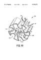
- FIG. 8is a perspective exploded view of a second embodiment of a spool caddy having a body, a snap ring and a binding lever for use during dry optical image processing of roll film;
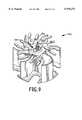
- FIG. 9is a top side perspective view of the assembled spool caddy of FIG. 8;
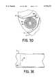
- FIG. 10is a bottom side perspective view of the spool caddy of FIG. 8.
- FIG. 11is a side view of a preferred embodiment of a binding lever for use with the spool caddy of FIG. 8.
- FIG. 1is a perspective exploded view of a first embodiment of a spool caddy 1 which conforms to the principles of the present invention.
- the three major components of the spool caddy 1are the body 10, the snap plate 40 and the binding lever 60.
- Each of the major componentsis preferably molded or otherwise made from a strong, inexpensive, lightweight material such as polystyrene or any other plastic. These components when assembled together form the spool caddy 1, shown with a single processing spool 80 in FIG. 2.
- the body 10acts as means, as shown in FIG. 3C, for detachably securing and supporting a number of processing spools 80, 90, 100, 110, as well as the film cartridge 70, in isolation from one another.
- the body 10includes a base 12, a plurality of arms 14 and a wedge shaped cavity 20 positioned along the central longitudinal axis 16 of the spool caddy 1.
- the cavity 20is indexed, notched or keyed in a lower section of the body by a rectangular notch 22.
- a slot 24 for engaging a film leader 76 of the film cartridge 70extends from the cavity 20 as shown.
- the body 10is keyed by a notch 18 as shown in FIG.
- the spool caddy 200 of FIGS. 8 and 9can be aligned with any external structure (not shown) via a keyed binding lever 204 as shown in FIG. 11.
- the binding lever 204includes a knurled top section 222, a retaining ring 224, an annular rib 226 and a lower section 228.
- the lower section 228in this case is oval shaped for a snug fit into the lower section 230 (see FIG. 10) of the cavity 212.
- the section 228is designed to extend beyond the plane of the base 210 for cooperation with an appropriately shaped receptacle in an external structure, so that the spool caddy 200 will be keyed, i.e. positionally aligned, to the external structure.
- the snap plate 40having a thickness "z" includes a centrally located cavity shaped opening 46 similar in shape to the cavity 20 of the body 10, as well as a slot 25 corresponding to the slot 24 of the body 10.
- the snap plate 40functions as means for detachably retaining or holding both a plurality of processing spools, such as the processing spool 80 of FIG. 2, and the film cartridge 70 of FIG. 6A.
- the snap plate 40may be clover shaped as shown in FIGS. 1 and 2, or its shape could vary as shown by the snap plate 140 of FIG. 4, as long as it has the ability to detachably retain processing spools and film cartridges.
- the snap plates 40 and 140are both capable of detachably holding five spools, although the snap plates could be designed in cooperation with the spool caddy 1 to retain more or less spools if desired.
- the snap plate 40 of FIG. 2includes five identical leaf shaped sections 50 defining five identical spaces therebetween, each space having a cross-sectional distance "a” and a narrow region of distance "m” at the perimeter of the snap plate 40.
- the snap plate 140 of FIG. 4includes five claw shaped arms 45 each having a pair of claws 49 and 51 which also define five identical spaces therebetween each having a cross-sectional distance "a” and a narrow distance "m” located near the ends of the claws.
- the snap plate 40 or 140 and the body 10can be glued together, snapped together, screwed together, or otherwise held together by any known fastening means.
- the embodiment of FIG. 1provides clearance holes 42 in the snap plate 40 and raised bosses 44 on the body 10 which allows the two parts to be joined together by ultrasonic staking to form the body/snap plate assembly.
- the snap plate 140 of FIG. 4includes clearance holes 43 which would be aligned with appropriately positioned raised bosses (not shown) replacing the bosses 44 on the body 10.
- the snap plate 140also includes centrally located cutouts 130, 132 and 134 as illustrated in FIGS. 4 and 5B.
- Cutout 134is separated from the cutout 130 by a section 133
- cutout 132is separated from the cutout 130 by a section 131.
- the binding lever 60is designed as a means for detachably retaining, in cooperation with the body 10, a film leader 76 of the film 71.
- the film leader 76is inserted into the cavity 20 of the caddy body 10
- the binding lever 60is inserted through the top of the body/snap plate assembly so that the spring 62 is aligned with, and snaps into, the notch 22.
- the diameter x 5 of the head 64 of the binding lever 60is large enough so that the head 64 can not pass into or through the cavity 20.
- the force of the spring 62pushes the spring 62 against the internal wall of the notch 22 to securely bind the lever 60 in the cavity 20.
- the binding lever 60is inserted into the cavity 20 it cannot be removed.
- the head 64 and the indent 66 of the binding lever 60will both protrude above the snap plate 40 as shown in FIG. 2 to act in cooperation as a handle for inserting and removing the spool caddy I from a pad processing system.
- the binding lever 60 of FIG. 1includes: a shaft 68 of diameter x 6 and height x 1 ; an indent 66 of length x 3 ; a head 64 having a diameter x 5 and a thickness x 4 ; and a spring 62 of length x 7 having a spring force which tends to extend the spring 62 away from the shaft 68 as shown.
- the length x 7defines the distance from the bottom of the shaft 68 to the top end of the spring 62.
- the length x 7also corresponds to the length "k" of the notch 22 located adjacent to the lower portion of the cavity 20 in the caddy body 10.
- the distance x 1 of the shaft 68 of the binding lever 60equates to the sum of the height "w" of the caddy body 10 and the width "z” of the snap plate 40 so that when the spool caddy 1 is completely assembled as shown in FIG. 2, the shaft head 64 and the indent 66 both protrude above the snap plate 40.
- any movement of the binding lever 60 in a direction crossing the central longitudinal axis 16 of the spool caddy 1is hampered by the force of the spring 62.
- any movement of the binding lever 60 in a direction parallel to the longitudinal axis 16is hampered by both the head 64 and the physical engagement of the spring 62 within the notch 22.
- the userWhen the user decides to process the film within a 35 mm film cartridge 70 using a spool caddy 1 having a snap plate 40 and a binding lever 60, he first feeds the film leader 76 into the slot 24 of the caddy body 10 and along the flat surface 125 of the cavity 20 (see FIGS. 2, 3B and 3C).
- the binding lever 60is inserted as described above so that the spring 62 snaps into the notch 22 and the film leader 76 becomes bound between the shaft 68 and the flat surface 125 in the cavity 20.
- the film cartridge 70is then detachably secured onto the spool caddy 1 by snapping the core 72 of the film cartridge 70 into the clover leaf shaped snap plate 40.
- the userlaterally applies pressure to the head 64 of the binding lever 60 so that the shaft 68 moves slightly away from the flat surface 125.
- a second type of binding lever 120 for use with the snap plate 140 of FIG. 4is shown in side view in FIG. 5A.
- the binding lever 120includes a shaft 128 having a cutout section 126.
- the shaft 128has a diameter y 4 , and further includes an annular rib 122 having a diameter greater than y 4 .
- the binding lever 120is designed to operate in cooperation with the cutout section 130 of the snap plate 140 (see FIGS. 4 and 5B).
- the binding lever 120is placed in an initial unlocked position as shown in FIG. 5C by inserting lever 120 through y 3 of the cutout 130 and into the body/snap plate assembly from the top until the spring 62 snaps into place within the notch 22.
- the binding lever 204 of FIG. 11 for use with the spool caddy 200 of FIG. 8has an annular rib 226 which functions in the same manner as the annular rib 122 of the binding lever 120 shown in FIGS. 5A, 5B and 5C.
- the top section 222is knurled for ease in gripping by the user.
- the lower section 228extends beyond the plane of the base 210 of the spool caddy 200 for cooperation with an appropriately shaped receptacle in an external structure (not shown) for positional alignment of the spool caddy 200.
- the retaining ring 224functionally replaces the spring 62 (see FIG. 5A) by securing the binding lever 204 in the slot 212.
- the spool caddy 200is assembled (without the spools installed) as shown in FIGS. 8 and 9 by inserting the binding lever 204 into the cavity 212 of the body 202, then overlaying the snap ring 206 and attaching (e.g. by gluing, snap-fitting, heat sealing, etc.) the snap ring 206 onto the body 202.
- the retaining ring 224thereafter prevents removal of the binding lever 204 from the body 202.
- the binding lever 120When pushing the binding lever 120 into the locked position, the binding lever 120 passes from y 3 (see FIG. 5B) through the region y 2 of the cutout 130 and into the locked position of FIG. 5D corresponding to the region y 1 of the cutout 130.
- the sections 131 and 133will slightly bend away from the cutout 130 and into the respective cutouts 132 and 134, thus momentarily expanding the distance y 2 to allow passage of the binding lever shaft 128.
- the sections 131 and 133resiliently return to their original positions.
- the resultant locked position of the binding lever 120is illustrated in FIG.
- the film cartridge 70can be detachably secured onto the spool caddy 1 by snapping the core 72 of the film cartridge 70 between two claws 49 and 51 of the snap plate 140.
- the film leader 76can be readily removed from the binding lever 120 by moving the binding lever 120 into its unlocked or release position. This is accomplished by pushing the head 124 of the binding lever 120 from y 1 through y 2 and into y 3 , as viewed in FIG. 5B, whereby the film leader 76 is then loosely positioned between the annular rib 122 of the shaft 128 and the flat surface 125 to facilitate removal therefrom.
- the processing spools 80, 90, 100 and 110 of the current embodimentare each factory installed into the spool caddy 1 in the same manner in which processing spool 80 is shown to be installed in FIG. 2.
- Each processing spool as well as a standard 35 mm film cartridge 70contains a hollow core 72 with dual drive tangs 74 recessed therein (see FIGS. 6A, 6B, 6C, 7A, 7B and 7C) for transferring rotational drive force from a source (not shown) to the core 72.
- the structure and dimensions of each processing spool 80, 90, 100 and 110is similar to that shown in FIGS. 7A, 7B and 7C.
- Each processing spool and film cartridgecontains a core 72 of diameter h 1 which protrudes from one end of the body of the spool or cartridge by a height h 2 .
- the snap plates 40 and 140are made of a flexible, resilient plastic which allows resilient spreading of the leaf sections 50 in the snap plate 40 and the claws 49 and 51 in the snap plate 140 during insertion or removal of the core 72.
- Each processing spoolcontains a web having a protruding leader which is fixedly attached to one arm 14 of the caddy body 10 as shown in FIG. 3C.
- the web 82 of spool 80has a protruding leader 86 which is fixedly attached to one arm 14 at point 84.
- the web 82can be secured to the body 10 as shown in FIG. 3D via a nub 81 located at the end of the web 82 which is inserted into a slot 83 during installation of the processing spool 80 into the spool caddy 1.
- 3Eillustrates a web 82 connected to arm 14 via a rivet 15 which allows pivoting of the web 82 about the rivet 15 during unwinding and rewinding of the web 82 onto the spool 80.
- Any other known meanscan be used for fastening the web 82 to the body of the spool caddy.
- spool 80is a developer spool which contains a reagent laden web 82 imbibed with developing chemicals
- spool 90is a blix (i.e. bleaching and fixing) spool which contains a reagent laden web 92 imbibed with a combination of bleaching and fixing chemicals
- spool 100is a wash spool which contains a web 102 soaked with a combination of washing and stabilizing agents
- spool 110is a blotter spool which contains a web 112 of dry non-woven material.
- the assembled spool caddy 1contains the body 10, the snap plate 40, the binding lever 60, and the preselected processing spools.
- the number and contents of the processing spools of a particular spool caddycan vary according to the needs for processing a particular roll film. For instance, if separate bleaching and fixing steps are desired, then the blix spool 90 could be replaced by two separate spools, one containing a reagent laden web imbibed with bleaching chemicals, and the other containing a reagent laden web imbibed with fixing chemicals.
- the spool caddy 1would then require six arms 14 and the snap plate 40 would require six leaf shaped sections 50.
- processing spools with other processing capabilitiescould be added to the spool caddy 1 if desired.
- the number of arms 14 on the caddy body 10 and the number of leaf shaped sections 50 on the snap plate 40, or claws 45 on the snap plate 140can change in accordance with the number of spools desired or required for film processing.
- the arms 14can take any desired shape as long as they provide both support for the various spools, and isolation of those spools from one another.
- any snap plate designmay be used that allows the snap plate to detachably hold each spool in place.
- the processing spoolscould be encased in hard shell cartridges, similar to 35 m cartridges, so that a snap plate could detachably retain the bodies of the hard shell processing cartridges, rather than the cores as described above.
- a modified version of the above-described spool caddy 1would house only the processing spools, i.e. the modified spool caddy 1 would not house the film cartridge 70.
- the structural components of the spool caddy 1 which interact solely with the film 71 or the film cartridge 70become unnecessary. In other words, the binding lever 60, the slot 24 and the cavity 20 would no longer be needed.
- FIG. 8is a perspective exploded view of a second embodiment of a spool caddy 200 which conforms to the principles of the present invention.
- the three major components of the spool caddy 200are the body 202, the snap ring 206 and the binding lever 204.
- Each of the major componentsis preferably molded or otherwise made from a strong, inexpensive, lightweight material such as polystyrene or any other plastic. These components when assembled together form the spool caddy 200, shown assembled (without processing spools) in FIG. 9.
- the operability of the three components 202, 204 and 206is similar to that of the previously described parts 10, 60 and 40, respectively shown in the spool caddy 1 of FIG. 1.
- the body 200is similar to the body 10 by functioning to detachably secure and support a group of processing spools, plus a film cartridge, in isolation from one another.
- the body 200includes a base 210, a plurality of arms 208 and a cavity 212 positioned along the central longitudinal axis 218 of the spool caddy 200.
- the body 200also includes a spacer section 219, located between two arms 208, which can be enlarged, diminished or eliminated as necessary to provide proper spacing and orientation of the desired number of processing spools to be mounted on the body 200.
- the body 202 of the spool caddy 200is a single molded piece which includes a plurality of claw-shaped arms 45 each having a pair of claws 49 and 51.
- a processing spool or film cartridgeis installed onto the spool caddy 200 by snapping the core 72 of the selected spool between the claws 49 and 51 in the same manner as shown for the embodiment of FIG. 2.
- each selected spoolcan be mounted or removed from the body 202 via cutouts 214 which allow the bottom portion (opposite core 72) of the selected spool to be engaged by a mechanism (not shown) for removing or returning the selected spool from or to the spool caddy 200, respectively.
- inventive spool caddy as claimed and described herein in various embodimentscan be used for pad processing any photographic roll film with a variety of image processing systems such as, but not limited to, the processing systems disclosed in Polaroid Case No. 8221 filed on even date herewith.
- image processing systemssuch as, but not limited to, the processing systems disclosed in Polaroid Case No. 8221 filed on even date herewith.
- the functionality of the spool caddy in cooperation with other elements of a pad processing systemare described in detail in the above related patent application.
Landscapes
- Physics & Mathematics (AREA)
- General Physics & Mathematics (AREA)
- Photographic Developing Apparatuses (AREA)
Abstract
Description
Claims (18)
Priority Applications (1)
| Application Number | Priority Date | Filing Date | Title |
|---|---|---|---|
| US09/038,506US5970271A (en) | 1997-03-11 | 1998-03-11 | Spool caddy for use with dry optical image processing of roll film |
Applications Claiming Priority (3)
| Application Number | Priority Date | Filing Date | Title |
|---|---|---|---|
| US4038897P | 1997-03-11 | 1997-03-11 | |
| US4066297P | 1997-03-11 | 1997-03-11 | |
| US09/038,506US5970271A (en) | 1997-03-11 | 1998-03-11 | Spool caddy for use with dry optical image processing of roll film |
Publications (1)
| Publication Number | Publication Date |
|---|---|
| US5970271Atrue US5970271A (en) | 1999-10-19 |
Family
ID=27365409
Family Applications (1)
| Application Number | Title | Priority Date | Filing Date |
|---|---|---|---|
| US09/038,506Expired - Fee RelatedUS5970271A (en) | 1997-03-11 | 1998-03-11 | Spool caddy for use with dry optical image processing of roll film |
Country Status (1)
| Country | Link |
|---|---|
| US (1) | US5970271A (en) |
Cited By (2)
| Publication number | Priority date | Publication date | Assignee | Title |
|---|---|---|---|---|
| US20030091413A1 (en)* | 2001-11-09 | 2003-05-15 | Yergenson Robin P. | Object retention in a rotatable carousel |
| US20050019140A1 (en)* | 2000-10-13 | 2005-01-27 | Hund Henry M. | Refuse collection vehicle having multiple collection assemblies |
Citations (26)
| Publication number | Priority date | Publication date | Assignee | Title |
|---|---|---|---|---|
| US2558857A (en)* | 1947-02-08 | 1951-07-03 | Polaroid Corp | Photographic developer element |
| US3345165A (en)* | 1963-07-31 | 1967-10-03 | Polaroid Corp | Photographic product and process of using same |
| US3380679A (en)* | 1966-04-25 | 1968-04-30 | Mark Systems Inc | Mat processor |
| US3416921A (en)* | 1965-02-01 | 1968-12-17 | Minnesota Mining & Mfg | Photographic processing using cellophane processing sheets |
| US3576632A (en)* | 1967-04-28 | 1971-04-27 | Elmer S Bornemisza | Multilayered photographic processing web |
| US3615482A (en)* | 1969-12-17 | 1971-10-26 | Itek Corp | Gelable photoprocessing solutions |
| US3647464A (en)* | 1970-04-22 | 1972-03-07 | Eastman Kodak Co | Sulfonated poly(vinyl alcohol) derivatives as absorbent layers in photographic processing webs |
| US3681254A (en)* | 1970-03-30 | 1972-08-01 | Itek Corp | Method of forming a gelable dispersion |
| US3680462A (en)* | 1970-12-10 | 1972-08-01 | Itek Corp | Gel photo processing apparatus |
| US3689272A (en)* | 1971-01-25 | 1972-09-05 | Eastman Kodak Co | Photographic color processes which yield either positive or negative silver-transfer images |
| US3816136A (en)* | 1972-07-17 | 1974-06-11 | Eastman Kodak Co | Photographic element and process of developing |
| US3826653A (en)* | 1972-09-18 | 1974-07-30 | Bell & Howell Co | Photographic developing system and method |
| US3907563A (en)* | 1973-12-13 | 1975-09-23 | Polaroid Corp | Diffusion transfer process using processing composition impregnated image-receiving element |
| US3930859A (en)* | 1973-07-20 | 1976-01-06 | Bell & Howell Company | Photographic process, system, recording medium and monoweb |
| US4309100A (en)* | 1980-11-17 | 1982-01-05 | Polaroid Corporation | Film processor for instant type transparency film |
| US4370045A (en)* | 1982-03-01 | 1983-01-25 | Polaroid Corporation | Film processor |
| US4452523A (en)* | 1982-06-24 | 1984-06-05 | Polaroid Corporation | Method of and apparatus for processing film |
| US4605608A (en)* | 1985-09-23 | 1986-08-12 | Polaroid Corporation | Image-receiving element with crosslinked hydrophilic polymer containing processing composition |
| US5200295A (en)* | 1990-12-18 | 1993-04-06 | Agfa-Gevaert N.V. | Method for the production of a silver image |
| US5229246A (en)* | 1990-02-20 | 1993-07-20 | Fuji Photo Film Co., Ltd. | Photographic materials containing polysaccharides |
| US5325144A (en)* | 1992-04-20 | 1994-06-28 | Fuji Photo Film Co., Ltd. | Photographic film curling correcting method and apparatus |
| US5440366A (en)* | 1994-07-22 | 1995-08-08 | Polaroid Corporation | Multi-pad film processing |
| US5450160A (en)* | 1993-12-22 | 1995-09-12 | Eastman Kodak Company | Film cartridge magazine |
| US5473402A (en)* | 1993-12-22 | 1995-12-05 | Eastman Kodak Company | Film processing system |
| US5478703A (en)* | 1991-12-18 | 1995-12-26 | Eastman Kodak Company | Method and material for photographic processing |
| EP0800114A2 (en)* | 1996-03-11 | 1997-10-08 | Fuji Photo Film Co., Ltd. | Image forming method and system |
- 1998
- 1998-03-11USUS09/038,506patent/US5970271A/ennot_activeExpired - Fee Related
Patent Citations (26)
| Publication number | Priority date | Publication date | Assignee | Title |
|---|---|---|---|---|
| US2558857A (en)* | 1947-02-08 | 1951-07-03 | Polaroid Corp | Photographic developer element |
| US3345165A (en)* | 1963-07-31 | 1967-10-03 | Polaroid Corp | Photographic product and process of using same |
| US3416921A (en)* | 1965-02-01 | 1968-12-17 | Minnesota Mining & Mfg | Photographic processing using cellophane processing sheets |
| US3380679A (en)* | 1966-04-25 | 1968-04-30 | Mark Systems Inc | Mat processor |
| US3576632A (en)* | 1967-04-28 | 1971-04-27 | Elmer S Bornemisza | Multilayered photographic processing web |
| US3615482A (en)* | 1969-12-17 | 1971-10-26 | Itek Corp | Gelable photoprocessing solutions |
| US3681254A (en)* | 1970-03-30 | 1972-08-01 | Itek Corp | Method of forming a gelable dispersion |
| US3647464A (en)* | 1970-04-22 | 1972-03-07 | Eastman Kodak Co | Sulfonated poly(vinyl alcohol) derivatives as absorbent layers in photographic processing webs |
| US3680462A (en)* | 1970-12-10 | 1972-08-01 | Itek Corp | Gel photo processing apparatus |
| US3689272A (en)* | 1971-01-25 | 1972-09-05 | Eastman Kodak Co | Photographic color processes which yield either positive or negative silver-transfer images |
| US3816136A (en)* | 1972-07-17 | 1974-06-11 | Eastman Kodak Co | Photographic element and process of developing |
| US3826653A (en)* | 1972-09-18 | 1974-07-30 | Bell & Howell Co | Photographic developing system and method |
| US3930859A (en)* | 1973-07-20 | 1976-01-06 | Bell & Howell Company | Photographic process, system, recording medium and monoweb |
| US3907563A (en)* | 1973-12-13 | 1975-09-23 | Polaroid Corp | Diffusion transfer process using processing composition impregnated image-receiving element |
| US4309100A (en)* | 1980-11-17 | 1982-01-05 | Polaroid Corporation | Film processor for instant type transparency film |
| US4370045A (en)* | 1982-03-01 | 1983-01-25 | Polaroid Corporation | Film processor |
| US4452523A (en)* | 1982-06-24 | 1984-06-05 | Polaroid Corporation | Method of and apparatus for processing film |
| US4605608A (en)* | 1985-09-23 | 1986-08-12 | Polaroid Corporation | Image-receiving element with crosslinked hydrophilic polymer containing processing composition |
| US5229246A (en)* | 1990-02-20 | 1993-07-20 | Fuji Photo Film Co., Ltd. | Photographic materials containing polysaccharides |
| US5200295A (en)* | 1990-12-18 | 1993-04-06 | Agfa-Gevaert N.V. | Method for the production of a silver image |
| US5478703A (en)* | 1991-12-18 | 1995-12-26 | Eastman Kodak Company | Method and material for photographic processing |
| US5325144A (en)* | 1992-04-20 | 1994-06-28 | Fuji Photo Film Co., Ltd. | Photographic film curling correcting method and apparatus |
| US5450160A (en)* | 1993-12-22 | 1995-09-12 | Eastman Kodak Company | Film cartridge magazine |
| US5473402A (en)* | 1993-12-22 | 1995-12-05 | Eastman Kodak Company | Film processing system |
| US5440366A (en)* | 1994-07-22 | 1995-08-08 | Polaroid Corporation | Multi-pad film processing |
| EP0800114A2 (en)* | 1996-03-11 | 1997-10-08 | Fuji Photo Film Co., Ltd. | Image forming method and system |
Cited By (2)
| Publication number | Priority date | Publication date | Assignee | Title |
|---|---|---|---|---|
| US20050019140A1 (en)* | 2000-10-13 | 2005-01-27 | Hund Henry M. | Refuse collection vehicle having multiple collection assemblies |
| US20030091413A1 (en)* | 2001-11-09 | 2003-05-15 | Yergenson Robin P. | Object retention in a rotatable carousel |
Similar Documents
| Publication | Publication Date | Title |
|---|---|---|
| CZ275492A3 (en) | Casing for a cassette with a disk | |
| JP5367713B2 (en) | Reagent container system | |
| WO2021201070A1 (en) | Developing cartridge, drum cartridge, and process unit | |
| US20210311410A1 (en) | Developing cartridge including movable holder for holding electrical contact surface | |
| US5970271A (en) | Spool caddy for use with dry optical image processing of roll film | |
| US20210311412A1 (en) | Image forming apparatus including first and second guide frames for guiding attachment of drum cartridge to which developing cartridge is attached | |
| WO1998040786A1 (en) | Spool caddy for use with processing of roll film by means of applicator webs | |
| JPH0962099A (en) | Image forming device | |
| US5993080A (en) | System for optical dry processing of spooled photographic film | |
| JP2018118401A (en) | Ink ribbon cassette, cassette case thereof, ink ribbon storage container, assembly of cassette case and ink ribbon storage container, assembling method of ink ribbon cassette and assembling method of ink ribbon storage container | |
| US4887113A (en) | Film cassette and method of assembling the same | |
| US5499781A (en) | Film spool with axially flexible core to engage and release film end | |
| CN218298778U (en) | Developing box and chip support | |
| US5449125A (en) | Film spool with internal flexures to engage and release film end | |
| US12443125B2 (en) | Developing cartridge including movable holder for holding electrical contact surface | |
| JP3035043U (en) | Advanced photo system compatible cartridge index print matching file | |
| JP7692805B2 (en) | Camera equipment | |
| JP3345864B2 (en) | Cartridge storage album | |
| JPS63210951A (en) | Image forming device | |
| JP6970919B2 (en) | Ink ribbon storage container | |
| CN215576123U (en) | Photosensitive unit and process cartridge | |
| JP2823949B2 (en) | Photo film patrone | |
| US5445343A (en) | Film spool with integral cantilever to engage and release film end | |
| US6157784A (en) | Film cassette having loosely-retained, reversibly separable memory module, and photographic apparatus | |
| JP3035042U (en) | Advanced photo system compatible cartridge index print matching file |
Legal Events
| Date | Code | Title | Description |
|---|---|---|---|
| AS | Assignment | Owner name:POLAROID CORPORATION, MASSACHUSETTS Free format text:ASSIGNMENT OF ASSIGNORS INTEREST;ASSIGNOR:CLOUGH, ARTHUR H.;REEL/FRAME:009031/0319 Effective date:19980310 | |
| AS | Assignment | Owner name:MORGAN GUARANTY TRUST COMPANY OF NEW YORK, NEW YOR Free format text:SECURITY AGREEMENT;ASSIGNOR:POLAROID CORPORATION;REEL/FRAME:011658/0699 Effective date:20010321 | |
| FPAY | Fee payment | Year of fee payment:4 | |
| AS | Assignment | Owner name:OEP IMAGINIG OPERATING CORPORATION, NEW YORK Free format text:ASSIGNMENT OF ASSIGNORS INTEREST;ASSIGNOR:POLAROID CORPORATION;REEL/FRAME:016427/0144 Effective date:20020731 Owner name:POLAROID CORPORATION, NEW YORK Free format text:CHANGE OF NAME;ASSIGNOR:OEP IMAGING OPERATING CORPORATION;REEL/FRAME:016470/0006 Effective date:20020801 Owner name:OEP IMAGINIG OPERATING CORPORATION,NEW YORK Free format text:ASSIGNMENT OF ASSIGNORS INTEREST;ASSIGNOR:POLAROID CORPORATION;REEL/FRAME:016427/0144 Effective date:20020731 Owner name:POLAROID CORPORATION,NEW YORK Free format text:CHANGE OF NAME;ASSIGNOR:OEP IMAGING OPERATING CORPORATION;REEL/FRAME:016470/0006 Effective date:20020801 | |
| AS | Assignment | Owner name:WILMINGTON TRUST COMPANY, AS COLLATERAL AGENT, DEL Free format text:ASSIGNMENT OF ASSIGNORS INTEREST;ASSIGNORS:POLAROLD HOLDING COMPANY;POLAROID CORPORATION;POLAROID ASIA PACIFIC LLC;AND OTHERS;REEL/FRAME:016602/0332 Effective date:20050428 Owner name:JPMORGAN CHASE BANK,N.A,AS ADMINISTRATIVE AGENT, W Free format text:SECURITY INTEREST;ASSIGNORS:POLAROID HOLDING COMPANY;POLAROID CORPORATION;POLAROID ASIA PACIFIC LLC;AND OTHERS;REEL/FRAME:016602/0603 Effective date:20050428 Owner name:WILMINGTON TRUST COMPANY, AS COLLATERAL AGENT,DELA Free format text:SECURITY AGREEMENT;ASSIGNORS:POLAROLD HOLDING COMPANY;POLAROID CORPORATION;POLAROID ASIA PACIFIC LLC;AND OTHERS;REEL/FRAME:016602/0332 Effective date:20050428 Owner name:JPMORGAN CHASE BANK,N.A,AS ADMINISTRATIVE AGENT,WI Free format text:SECURITY INTEREST;ASSIGNORS:POLAROID HOLDING COMPANY;POLAROID CORPORATION;POLAROID ASIA PACIFIC LLC;AND OTHERS;REEL/FRAME:016602/0603 Effective date:20050428 Owner name:WILMINGTON TRUST COMPANY, AS COLLATERAL AGENT, DEL Free format text:SECURITY AGREEMENT;ASSIGNORS:POLAROLD HOLDING COMPANY;POLAROID CORPORATION;POLAROID ASIA PACIFIC LLC;AND OTHERS;REEL/FRAME:016602/0332 Effective date:20050428 | |
| AS | Assignment | Owner name:POLAROID CORPORATION (F/K/A OEP IMAGING OPERATING Free format text:U.S. BANKRUPTCY COURT DISTRICT OF DELAWARE ORDER AUTHORIZING RELEASE OF ALL LIENS;ASSIGNOR:JPMORGAN CHASE BANK, N.A. (F/K/A MORGAN GUARANTY TRUST COMPANY OF NEW YORK);REEL/FRAME:016621/0377 Effective date:20020418 | |
| AS | Assignment | Owner name:OEP IMAGING OPERATING CORPORATION,NEW YORK Free format text:ASSIGNMENT OF ASSIGNORS INTEREST;ASSIGNOR:POLAROID CORPORATION;REEL/FRAME:018584/0600 Effective date:20020731 Owner name:OEP IMAGING OPERATING CORPORATION, NEW YORK Free format text:ASSIGNMENT OF ASSIGNORS INTEREST;ASSIGNOR:POLAROID CORPORATION;REEL/FRAME:018584/0600 Effective date:20020731 | |
| AS | Assignment | Owner name:POLAROID CORPORATION (FMR OEP IMAGING OPERATING CO Free format text:SUPPLEMENTAL ASSIGNMENT OF PATENTS;ASSIGNOR:PRIMARY PDC, INC. (FMR POLAROID CORPORATION);REEL/FRAME:019077/0001 Effective date:20070122 | |
| FPAY | Fee payment | Year of fee payment:8 | |
| AS | Assignment | Owner name:POLAROID HOLDING COMPANY, MASSACHUSETTS Free format text:RELEASE OF SECURITY INTEREST IN PATENTS;ASSIGNOR:WILMINGTON TRUST COMPANY;REEL/FRAME:019699/0512 Effective date:20070425 Owner name:POLAROID CORPORATION, MASSACHUSETTS Free format text:RELEASE OF SECURITY INTEREST IN PATENTS;ASSIGNOR:WILMINGTON TRUST COMPANY;REEL/FRAME:019699/0512 Effective date:20070425 Owner name:POLAROID CAPITAL LLC, MASSACHUSETTS Free format text:RELEASE OF SECURITY INTEREST IN PATENTS;ASSIGNOR:WILMINGTON TRUST COMPANY;REEL/FRAME:019699/0512 Effective date:20070425 Owner name:POLAROID ASIA PACIFIC LLC, MASSACHUSETTS Free format text:RELEASE OF SECURITY INTEREST IN PATENTS;ASSIGNOR:WILMINGTON TRUST COMPANY;REEL/FRAME:019699/0512 Effective date:20070425 Owner name:POLAROID EYEWEAR LLC, MASSACHUSETTS Free format text:RELEASE OF SECURITY INTEREST IN PATENTS;ASSIGNOR:WILMINGTON TRUST COMPANY;REEL/FRAME:019699/0512 Effective date:20070425 Owner name:POLOROID INTERNATIONAL HOLDING LLC, MASSACHUSETTS Free format text:RELEASE OF SECURITY INTEREST IN PATENTS;ASSIGNOR:WILMINGTON TRUST COMPANY;REEL/FRAME:019699/0512 Effective date:20070425 Owner name:POLAROID INVESTMENT LLC, MASSACHUSETTS Free format text:RELEASE OF SECURITY INTEREST IN PATENTS;ASSIGNOR:WILMINGTON TRUST COMPANY;REEL/FRAME:019699/0512 Effective date:20070425 Owner name:POLAROID LATIN AMERICA I CORPORATION, MASSACHUSETT Free format text:RELEASE OF SECURITY INTEREST IN PATENTS;ASSIGNOR:WILMINGTON TRUST COMPANY;REEL/FRAME:019699/0512 Effective date:20070425 Owner name:POLAROID NEW BEDFORD REAL ESTATE LLC, MASSACHUSETT Free format text:RELEASE OF SECURITY INTEREST IN PATENTS;ASSIGNOR:WILMINGTON TRUST COMPANY;REEL/FRAME:019699/0512 Effective date:20070425 Owner name:POLAROID NORWOOD REAL ESTATE LLC, MASSACHUSETTS Free format text:RELEASE OF SECURITY INTEREST IN PATENTS;ASSIGNOR:WILMINGTON TRUST COMPANY;REEL/FRAME:019699/0512 Effective date:20070425 Owner name:POLAROID WALTHAM REAL ESTATE LLC, MASSACHUSETTS Free format text:RELEASE OF SECURITY INTEREST IN PATENTS;ASSIGNOR:WILMINGTON TRUST COMPANY;REEL/FRAME:019699/0512 Effective date:20070425 Owner name:PETTERS CONSUMER BRANDS, LLC, MASSACHUSETTS Free format text:RELEASE OF SECURITY INTEREST IN PATENTS;ASSIGNOR:WILMINGTON TRUST COMPANY;REEL/FRAME:019699/0512 Effective date:20070425 Owner name:PETTERS CONSUMER BRANDS INTERNATIONAL, LLC, MASSAC Free format text:RELEASE OF SECURITY INTEREST IN PATENTS;ASSIGNOR:WILMINGTON TRUST COMPANY;REEL/FRAME:019699/0512 Effective date:20070425 Owner name:ZINK INCORPORATED, MASSACHUSETTS Free format text:RELEASE OF SECURITY INTEREST IN PATENTS;ASSIGNOR:WILMINGTON TRUST COMPANY;REEL/FRAME:019699/0512 Effective date:20070425 Owner name:POLAROID HOLDING COMPANY,MASSACHUSETTS Free format text:RELEASE OF SECURITY INTEREST IN PATENTS;ASSIGNOR:WILMINGTON TRUST COMPANY;REEL/FRAME:019699/0512 Effective date:20070425 Owner name:POLAROID CORPORATION,MASSACHUSETTS Free format text:RELEASE OF SECURITY INTEREST IN PATENTS;ASSIGNOR:WILMINGTON TRUST COMPANY;REEL/FRAME:019699/0512 Effective date:20070425 Owner name:POLAROID CAPITAL LLC,MASSACHUSETTS Free format text:RELEASE OF SECURITY INTEREST IN PATENTS;ASSIGNOR:WILMINGTON TRUST COMPANY;REEL/FRAME:019699/0512 Effective date:20070425 Owner name:POLAROID ASIA PACIFIC LLC,MASSACHUSETTS Free format text:RELEASE OF SECURITY INTEREST IN PATENTS;ASSIGNOR:WILMINGTON TRUST COMPANY;REEL/FRAME:019699/0512 Effective date:20070425 Owner name:POLAROID EYEWEAR LLC,MASSACHUSETTS Free format text:RELEASE OF SECURITY INTEREST IN PATENTS;ASSIGNOR:WILMINGTON TRUST COMPANY;REEL/FRAME:019699/0512 Effective date:20070425 Owner name:POLOROID INTERNATIONAL HOLDING LLC,MASSACHUSETTS Free format text:RELEASE OF SECURITY INTEREST IN PATENTS;ASSIGNOR:WILMINGTON TRUST COMPANY;REEL/FRAME:019699/0512 Effective date:20070425 Owner name:POLAROID INVESTMENT LLC,MASSACHUSETTS Free format text:RELEASE OF SECURITY INTEREST IN PATENTS;ASSIGNOR:WILMINGTON TRUST COMPANY;REEL/FRAME:019699/0512 Effective date:20070425 Owner name:POLAROID LATIN AMERICA I CORPORATION,MASSACHUSETTS Free format text:RELEASE OF SECURITY INTEREST IN PATENTS;ASSIGNOR:WILMINGTON TRUST COMPANY;REEL/FRAME:019699/0512 Effective date:20070425 Owner name:POLAROID NEW BEDFORD REAL ESTATE LLC,MASSACHUSETTS Free format text:RELEASE OF SECURITY INTEREST IN PATENTS;ASSIGNOR:WILMINGTON TRUST COMPANY;REEL/FRAME:019699/0512 Effective date:20070425 Owner name:POLAROID NORWOOD REAL ESTATE LLC,MASSACHUSETTS Free format text:RELEASE OF SECURITY INTEREST IN PATENTS;ASSIGNOR:WILMINGTON TRUST COMPANY;REEL/FRAME:019699/0512 Effective date:20070425 Owner name:POLAROID WALTHAM REAL ESTATE LLC,MASSACHUSETTS Free format text:RELEASE OF SECURITY INTEREST IN PATENTS;ASSIGNOR:WILMINGTON TRUST COMPANY;REEL/FRAME:019699/0512 Effective date:20070425 Owner name:PETTERS CONSUMER BRANDS, LLC,MASSACHUSETTS Free format text:RELEASE OF SECURITY INTEREST IN PATENTS;ASSIGNOR:WILMINGTON TRUST COMPANY;REEL/FRAME:019699/0512 Effective date:20070425 Owner name:PETTERS CONSUMER BRANDS INTERNATIONAL, LLC,MASSACH Free format text:RELEASE OF SECURITY INTEREST IN PATENTS;ASSIGNOR:WILMINGTON TRUST COMPANY;REEL/FRAME:019699/0512 Effective date:20070425 Owner name:ZINK INCORPORATED,MASSACHUSETTS Free format text:RELEASE OF SECURITY INTEREST IN PATENTS;ASSIGNOR:WILMINGTON TRUST COMPANY;REEL/FRAME:019699/0512 Effective date:20070425 | |
| AS | Assignment | Owner name:POLAROID HOLDING COMPANY, MASSACHUSETTS Free format text:RELEASE OF SECURITY INTEREST IN PATENTS;ASSIGNOR:JPMORGAN CHASE BANK, N.A.;REEL/FRAME:020733/0001 Effective date:20080225 Owner name:POLAROID INTERNATIONAL HOLDING LLC, MASSACHUSETTS Free format text:RELEASE OF SECURITY INTEREST IN PATENTS;ASSIGNOR:JPMORGAN CHASE BANK, N.A.;REEL/FRAME:020733/0001 Effective date:20080225 Owner name:POLAROID INVESTMENT LLC, MASSACHUSETTS Free format text:RELEASE OF SECURITY INTEREST IN PATENTS;ASSIGNOR:JPMORGAN CHASE BANK, N.A.;REEL/FRAME:020733/0001 Effective date:20080225 Owner name:POLAROID LATIN AMERICA I CORPORATION, MASSACHUSETT Free format text:RELEASE OF SECURITY INTEREST IN PATENTS;ASSIGNOR:JPMORGAN CHASE BANK, N.A.;REEL/FRAME:020733/0001 Effective date:20080225 Owner name:POLAROID NEW BEDFORD REAL ESTATE LLC, MASSACHUSETT Free format text:RELEASE OF SECURITY INTEREST IN PATENTS;ASSIGNOR:JPMORGAN CHASE BANK, N.A.;REEL/FRAME:020733/0001 Effective date:20080225 Owner name:POLAROID NORWOOD REAL ESTATE LLC, MASSACHUSETTS Free format text:RELEASE OF SECURITY INTEREST IN PATENTS;ASSIGNOR:JPMORGAN CHASE BANK, N.A.;REEL/FRAME:020733/0001 Effective date:20080225 Owner name:POLAROID WALTHAM REAL ESTATE LLC, MASSACHUSETTS Free format text:RELEASE OF SECURITY INTEREST IN PATENTS;ASSIGNOR:JPMORGAN CHASE BANK, N.A.;REEL/FRAME:020733/0001 Effective date:20080225 Owner name:POLAROID CONSUMER ELECTRONICS, LLC, (FORMERLY KNOW Free format text:RELEASE OF SECURITY INTEREST IN PATENTS;ASSIGNOR:JPMORGAN CHASE BANK, N.A.;REEL/FRAME:020733/0001 Effective date:20080225 Owner name:POLAROID CONSUMER ELECTRONICS INTERNATIONAL, LLC, Free format text:RELEASE OF SECURITY INTEREST IN PATENTS;ASSIGNOR:JPMORGAN CHASE BANK, N.A.;REEL/FRAME:020733/0001 Effective date:20080225 Owner name:ZINK INCORPORATED, MASSACHUSETTS Free format text:RELEASE OF SECURITY INTEREST IN PATENTS;ASSIGNOR:JPMORGAN CHASE BANK, N.A.;REEL/FRAME:020733/0001 Effective date:20080225 Owner name:POLAROID CORPORATION, MASSACHUSETTS Free format text:RELEASE OF SECURITY INTEREST IN PATENTS;ASSIGNOR:JPMORGAN CHASE BANK, N.A.;REEL/FRAME:020733/0001 Effective date:20080225 Owner name:POLAROID ASIA PACIFIC LLC, MASSACHUSETTS Free format text:RELEASE OF SECURITY INTEREST IN PATENTS;ASSIGNOR:JPMORGAN CHASE BANK, N.A.;REEL/FRAME:020733/0001 Effective date:20080225 Owner name:POLAROID CAPITAL LLC, MASSACHUSETTS Free format text:RELEASE OF SECURITY INTEREST IN PATENTS;ASSIGNOR:JPMORGAN CHASE BANK, N.A.;REEL/FRAME:020733/0001 Effective date:20080225 Owner name:PLLAROID EYEWEAR I LLC, MASSACHUSETTS Free format text:RELEASE OF SECURITY INTEREST IN PATENTS;ASSIGNOR:JPMORGAN CHASE BANK, N.A.;REEL/FRAME:020733/0001 Effective date:20080225 Owner name:POLAROID HOLDING COMPANY,MASSACHUSETTS Free format text:RELEASE OF SECURITY INTEREST IN PATENTS;ASSIGNOR:JPMORGAN CHASE BANK, N.A.;REEL/FRAME:020733/0001 Effective date:20080225 Owner name:POLAROID INTERNATIONAL HOLDING LLC,MASSACHUSETTS Free format text:RELEASE OF SECURITY INTEREST IN PATENTS;ASSIGNOR:JPMORGAN CHASE BANK, N.A.;REEL/FRAME:020733/0001 Effective date:20080225 Owner name:POLAROID INVESTMENT LLC,MASSACHUSETTS Free format text:RELEASE OF SECURITY INTEREST IN PATENTS;ASSIGNOR:JPMORGAN CHASE BANK, N.A.;REEL/FRAME:020733/0001 Effective date:20080225 Owner name:POLAROID LATIN AMERICA I CORPORATION,MASSACHUSETTS Free format text:RELEASE OF SECURITY INTEREST IN PATENTS;ASSIGNOR:JPMORGAN CHASE BANK, N.A.;REEL/FRAME:020733/0001 Effective date:20080225 Owner name:POLAROID NEW BEDFORD REAL ESTATE LLC,MASSACHUSETTS Free format text:RELEASE OF SECURITY INTEREST IN PATENTS;ASSIGNOR:JPMORGAN CHASE BANK, N.A.;REEL/FRAME:020733/0001 Effective date:20080225 Owner name:POLAROID NORWOOD REAL ESTATE LLC,MASSACHUSETTS Free format text:RELEASE OF SECURITY INTEREST IN PATENTS;ASSIGNOR:JPMORGAN CHASE BANK, N.A.;REEL/FRAME:020733/0001 Effective date:20080225 Owner name:POLAROID WALTHAM REAL ESTATE LLC,MASSACHUSETTS Free format text:RELEASE OF SECURITY INTEREST IN PATENTS;ASSIGNOR:JPMORGAN CHASE BANK, N.A.;REEL/FRAME:020733/0001 Effective date:20080225 Owner name:ZINK INCORPORATED,MASSACHUSETTS Free format text:RELEASE OF SECURITY INTEREST IN PATENTS;ASSIGNOR:JPMORGAN CHASE BANK, N.A.;REEL/FRAME:020733/0001 Effective date:20080225 Owner name:POLAROID CORPORATION,MASSACHUSETTS Free format text:RELEASE OF SECURITY INTEREST IN PATENTS;ASSIGNOR:JPMORGAN CHASE BANK, N.A.;REEL/FRAME:020733/0001 Effective date:20080225 Owner name:POLAROID ASIA PACIFIC LLC,MASSACHUSETTS Free format text:RELEASE OF SECURITY INTEREST IN PATENTS;ASSIGNOR:JPMORGAN CHASE BANK, N.A.;REEL/FRAME:020733/0001 Effective date:20080225 Owner name:POLAROID CAPITAL LLC,MASSACHUSETTS Free format text:RELEASE OF SECURITY INTEREST IN PATENTS;ASSIGNOR:JPMORGAN CHASE BANK, N.A.;REEL/FRAME:020733/0001 Effective date:20080225 Owner name:PLLAROID EYEWEAR I LLC,MASSACHUSETTS Free format text:RELEASE OF SECURITY INTEREST IN PATENTS;ASSIGNOR:JPMORGAN CHASE BANK, N.A.;REEL/FRAME:020733/0001 Effective date:20080225 | |
| AS | Assignment | Owner name:SENSHIN CAPITAL, LLC, DELAWARE Free format text:ASSIGNMENT OF ASSIGNORS INTEREST;ASSIGNOR:POLAROID CORPORATION;REEL/FRAME:021040/0001 Effective date:20080415 Owner name:SENSHIN CAPITAL, LLC,DELAWARE Free format text:ASSIGNMENT OF ASSIGNORS INTEREST;ASSIGNOR:POLAROID CORPORATION;REEL/FRAME:021040/0001 Effective date:20080415 | |
| FEPP | Fee payment procedure | Free format text:PAYER NUMBER DE-ASSIGNED (ORIGINAL EVENT CODE: RMPN); ENTITY STATUS OF PATENT OWNER: LARGE ENTITY Free format text:PAYOR NUMBER ASSIGNED (ORIGINAL EVENT CODE: ASPN); ENTITY STATUS OF PATENT OWNER: LARGE ENTITY | |
| REMI | Maintenance fee reminder mailed | ||
| LAPS | Lapse for failure to pay maintenance fees | ||
| STCH | Information on status: patent discontinuation | Free format text:PATENT EXPIRED DUE TO NONPAYMENT OF MAINTENANCE FEES UNDER 37 CFR 1.362 | |
| FP | Lapsed due to failure to pay maintenance fee | Effective date:20111019 | |
| AS | Assignment | Owner name:HANGER SOLUTIONS, LLC, GEORGIA Free format text:ASSIGNMENT OF ASSIGNORS INTEREST;ASSIGNOR:INTELLECTUAL VENTURES ASSETS 161 LLC;REEL/FRAME:052159/0509 Effective date:20191206 | |
| AS | Assignment | Owner name:INTELLECTUAL VENTURES ASSETS 161 LLC, DELAWARE Free format text:ASSIGNMENT OF ASSIGNORS INTEREST;ASSIGNOR:INTELLECTUAL VENTURES I LLC;REEL/FRAME:051945/0001 Effective date:20191126 |