US5970094A - Adaptive equalizer employing filter input circuit in a circular structure - Google Patents
Adaptive equalizer employing filter input circuit in a circular structureDownload PDFInfo
- Publication number
- US5970094A US5970094AUS08/964,758US96475897AUS5970094AUS 5970094 AUS5970094 AUS 5970094AUS 96475897 AUS96475897 AUS 96475897AUS 5970094 AUS5970094 AUS 5970094A
- Authority
- US
- United States
- Prior art keywords
- sample
- filter coefficient
- signal
- generate
- error
- Prior art date
- Legal status (The legal status is an assumption and is not a legal conclusion. Google has not performed a legal analysis and makes no representation as to the accuracy of the status listed.)
- Expired - Lifetime
Links
Images


Classifications
- H—ELECTRICITY
- H04—ELECTRIC COMMUNICATION TECHNIQUE
- H04B—TRANSMISSION
- H04B3/00—Line transmission systems
- H04B3/02—Details
- H04B3/04—Control of transmission; Equalising
- H—ELECTRICITY
- H03—ELECTRONIC CIRCUITRY
- H03H—IMPEDANCE NETWORKS, e.g. RESONANT CIRCUITS; RESONATORS
- H03H21/00—Adaptive networks
- H03H21/0012—Digital adaptive filters
- H—ELECTRICITY
- H04—ELECTRIC COMMUNICATION TECHNIQUE
- H04L—TRANSMISSION OF DIGITAL INFORMATION, e.g. TELEGRAPHIC COMMUNICATION
- H04L25/00—Baseband systems
- H04L25/02—Details ; arrangements for supplying electrical power along data transmission lines
- H04L25/03—Shaping networks in transmitter or receiver, e.g. adaptive shaping networks
- H04L25/03006—Arrangements for removing intersymbol interference
- H04L25/03012—Arrangements for removing intersymbol interference operating in the time domain
- H04L25/03019—Arrangements for removing intersymbol interference operating in the time domain adaptive, i.e. capable of adjustment during data reception
- H04L25/03038—Arrangements for removing intersymbol interference operating in the time domain adaptive, i.e. capable of adjustment during data reception with a non-recursive structure
Definitions
- the inventionrelates to an adaptive equalizer employing a least mean square(LMS) algorithm; and, more particularly, to an adaptive equalizer for effectively providing a series of input data samples and corresponding filter coefficients used in the filtering operation without using a conventional complex filter control circuit.
- LMSleast mean square
- a typical data signal receiving systemincludes a channel adaptive equalizer.
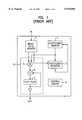
- FIG. 1there is shown a prior art channel adaptive equalizer which employs an input data memory 1 and filter coefficient memory 2 as a filter input circuit, a filter coefficient updater 3, a filtering block 10, and a control circuit 4.
- the input data memory 1receives an input data signal, which includes a plurality of input data samples, to sequentially provide a set of window data samples for each data sample to be filtered under the control of the control circuit 4.
- the filter coefficient memory 2serves to store updated filter coefficients outputted from the filter coefficient updater 3 to sequentially provide the updated filter coefficients as a corresponding set of filter coefficients to the filtering block 10 under the control of the control circuit 4.
- the filtering block 10includes a multiplier 5 as a filter tap, an adder 6 as an accumulator, and a flip-flop 7; and serves to generate a filtered data sample by using the set of window data samples and the corresponding set of updated filter coefficients, thereby generating a filtered signal.
- the filtered signalhas a plurality of filtered data samples corresponding to the input data samples.
- the input data and the filter coefficient memoriesare generally implemented by using a random access memory (RAM).
- RAMrandom access memory
- the window data samples and the corresponding filter coefficientsare sequentially provided from the two memories, as the filter input circuit, under the control of the control circuit.
- a primary object of this inventionto provide an improved adaptive equalizer for effectively providing a series of input data samples and corresponding filter coefficients used in the filtering operation by using a circular structure, without using a conventional complex filter control circuit.
- an equalizerfor filtering a received signal to generate a filtered signal, wherein the received signal includes a plurality of data samples and the filtered signal includes a corresponding plurality of filtered data samples
- said the equalizercomprising: data supply means, receiving the filtered signal, for generating N number of window data samples on a symbol-by-symbol basis by using (N+1) number of delay means arranged in a circular structure, N being a positive integer; multiply means for multiplying a window data sample with a current filter coefficient to generate a multiplied sample; accumulation means for accumulating the multiplied output sample to generate an accumulated sample; decision means for determining whether the accumulated sample approximates a desired sample and, if so, for generating a filtered data sample based on the accumulated sample; error generation means for generating an error value based on an error value, the current filter coefficient and the current window input sample, wherein the error signal represents a difference between the accumulated sample and the desired sample; and filter coefficient supply
- FIG. 1represents a schematic block diagram of a conventional channel adaptive equalizer employing a least mean square(LMS) algorithm
- FIG. 2shows a schematic block diagram of an adaptive equalizer in accordance with the present invention
- FIG. 3illustrates a detailed block diagram of the adaptive filter block shown in FIG. 2;
- FIG. 4provides a detailed block diagram of the filter coefficient updater shown in FIG. 2.
- the adaptive equalizerincludes adaptive filter blocks 11, 14, 17 and 20, filter coefficient updaters 12, 15, 18 and 21 , output signal decision blocks 13 and 16.
- the adaptive equalizeris implemented by employing two equalization parts, wherein one has two adaptive filter blocks 11 and 14, two filter coefficient updaters 12 and 15 and two output decision blocks 13 and 16; and the other contains two adaptive filters 17 and 20, two filter coefficient updaters 18 and 21, and two subtracters 19 and 22.
- the adaptive equalizercan be operated as an known infinite impulse response (IIR) type adaptive equalizer through the use of the above two parts.
- IIRinfinite impulse response
- the adaptive filter blocks 11 and 14are arranged in a symmetric array. That is, the adaptive filter 11 serves to filter real data samples of input data signal, while the adaptive filter block 14 serves to filter imaginary data samples thereof.
- the output decision blocks 13 and 14receive outputs from the subtracters 13 and 16, respectively, and determine whether the outputs are assigned as an equalizer output signal that approximates an original non-distorted input data signal prior to its transmission.
- the adaptive filter blocks 11 and 14can be implemented by using a same filter structure. Accordingly, for the sake of convenience, the description hereinafter is directed to the filter block 11. Referring to FIG. 3, there is illustrated a detailed diagram of the adaptive filter block shown in FIG. 2.
- a received input data signalis sampled by a known sampling circuit into a plurality of input data samples.
- the plurality of data input sampleare sequentially coupled to the adaptive filter block 11 shown in FIG. 2.
- the adaptive filter block 11is comprised of a finite impulse response(FIR) filter 110 and a filter input circuit having an input data memory 101 and a filter coefficient memory 104.
- the input data signalis supplied via the input data memory 101 to the filter 110 in which it is filtered and equalized by using the set of filter coefficients from the filter coefficient memory 104 in order to produce a filtered signal.
- the filtered signalincludes a corresponding plurality of filtered data samples which are sequentially coupled to the filter coefficient updater 12 and also coupled via the subtracter 19 to the output decision block 13.
- an output F of the filter 110is calculated as follows: ##EQU1## wherein I is an input signal, C is an updated filter coefficient; and N is a positive integer.
- a finite impulse response filterperforms a filtering process for each target input data sample by sequentially multiplying N number of window data samples with N number of filter coefficients, respectively, and accumulates the multiplied data samples during a predetermined time T in order to generate a filtered data sample. The process is repeated to thereby generate a filtered data signal.
- the input data samplesare sequentially delayed by using (N+1) number of delay means arranged in a circular structure in order to generate N number of window data samples for each target input data sample in a sample-by-sample basis.
- (N+1)th delay meansis coupled to Nth delay means in a parallel fashion.
- Nth delayed data sample of the window data samplei.e., a first current window data sample
- the filter coefficient updater 12is relayed to the filter coefficient updater 12 as a current window data sample.
- a newly inputted data sampleis supplemented to the current window samples by using the multiplexer 102 to thereby form a new set of window input data samples for another target input data sample.
- LMSleast means square
- the input data memory 101is implemented by using N number, e.g., 8, of D flip-flops D1 to D8 arranged in a circular structure and an (N+1)th D flip-flop U1 coupled to an Nth D flip-flop D8 in a parallel fashion.
- N numbere.g. 8
- the input data samplesare sequentially relayed to a multiplier 106 which select the input data sample or output from the D flip-flop D8 in response to a selection signal.
- the selection signalcan be relayed from a known system controller(not shown).
- the selected input data sampleis then relayed vi D flip-flop 103 to the a first delay means, i.e., a D flip-flop D1 and the multipliers 106 and 107.
- the selected input data samplesare sequentially delayed by using the D flip-flops D1 to D8.
- a current set, e.g., 8, of window data samplesare sequentially supplied to the multiplier during the predetermined time T.
- An eighth delayed data sampleis vi D flip-flop U1 to the filter coefficient updater 15 shown in FIG. 2 as a current window data sample.
- a new input data sampleis then supplemented to the current set of window data samples to thereby form a new set of the window data samples.
- the operationwill be continued until all data samples contained in the input data signal is filtered.
- the filter coefficient memory 104is implemented by using N number, e.g., 8, of D flip-flops CD1 to CD8 arranged in a circular structure.
- a subtracter U2is connected between a first and second D flip-flops CD1 and CD2.
- the filter coefficientsare delayed by using the D flip-flops CD1 to CD 8 and a delayed filter coefficient output from the 8th D flip-flop CD8 is coupled to the multiplier 106 and a first D flip-flop CD1.
- the delayed filter coefficientis synchronized with the delayed window data sample by using the same clock signal and also, as designated by "Coefout", relayed to the adaptive filter 14 shown in FIG. 2.
- the subtracter U2serves to generate an updated filter coefficient by subtracting a filter coefficient outputted from the first D flip-flop CD1 with an error value outputted from the filter coefficient updater 12 shown in FIG. 2.
- the updated filter coefficientis then fed to the second D flip-flop CD2; delayed through the use of D flip-flops CD2 to CD8 in order to provide to the multiplier 106 when the corresponding window data sampled is applied thereto.
- the window data sampleis multiplied by the corresponding filter coefficient to generate a multiplied data sample.
- the multiplied data sampleis then relayed vin adder 107 to a flip-flop 108 which form an accumulator for accumulating the multiplied data sample to thereby generate a filtered data sample.
- the filtered data sampleis then relayed to the filter coefficient updater 12 and via subtracter 13 to output decision block 13.
- the filtered datais also multiplied by a multiplied symmetric imaginary data sample "Mulin" outputted from the adaptive filter 14 to generate another multiplied data sample "Mulout” which is relayed to the adaptive filter 14 shown in FIG. 2.
- a weight data "Addin" outputted from the adaptive filter 14can be added to the adder 107 in order to compensating a certain phase difference between a real and an image data samples.
- FIG. 4there is shown a schematic block diagram of the filter coefficient updater 12 in accordance with the present invention.
- the filter coefficient updater 12employs a least mean value algorithm.
- an updated filter coefficientis represented as follows:
- W k+1is an updated filter coefficient
- W kis a current filter coefficient
- ⁇is a convergence factor
- ⁇ kis an error signal
- X kis a current window data sample.
- the updated filter coefficientwhich is used for a next filtering operation, is obtained by subtracting the current filter coefficient with an error value, wherein the error value is obtained by multiplying the convergence factor by the current window data sample and the error signal.
- the error signalrepresents a difference between a filtered data sample and a corresponding desired data sample. Therefore, the filter coefficient updater 12 receives the filtered data sample and the current window data sample outputted from the adaptive filter 11 to generate the error value. The error value is then coupled to the filter coefficient memory 103 as described above.
- a subtracter 201calculates a different between the filtered data sample and the corresponding desired data sample to generate an error signal representing the difference.
- the error signalis then fed via flip flop 202 to a multiplier 203 in which the error signal is multiplied by a current window data sample to generate a multiplied error signal.
- the multiplied error signalis relayed to the shift register 204, wherein it is multiplied by a convergence factor through the use of a shifting operation to thereby generate an error value.
- the error valueis then supplied to the filter coefficient memory 104 shown in FIG. 3 in order to obtain a newly updated filter coefficient.
- the filter input circuite.g., an input data memory and the filter coefficient
- the filter input circuite.g., an input data memory and the filter coefficient
- the filter coefficientfor the adaptive filter having a filter multiplier and an accumulate, can be more effectively constructed only by using a number of delay means in a circular structure.
Landscapes
- Engineering & Computer Science (AREA)
- Computer Networks & Wireless Communication (AREA)
- Signal Processing (AREA)
- Power Engineering (AREA)
- Cable Transmission Systems, Equalization Of Radio And Reduction Of Echo (AREA)
- Filters That Use Time-Delay Elements (AREA)
- Digital Transmission Methods That Use Modulated Carrier Waves (AREA)
Abstract
Description
W.sub.k+1 =W.sub.k -με.sub.k X.sub.k
Claims (4)
Applications Claiming Priority (2)
| Application Number | Priority Date | Filing Date | Title |
|---|---|---|---|
| KR1019960052480AKR100201776B1 (en) | 1996-11-06 | 1996-11-06 | Adaptive equalizer with ring structure |
| KR96-52480 | 1996-11-06 |
Publications (1)
| Publication Number | Publication Date |
|---|---|
| US5970094Atrue US5970094A (en) | 1999-10-19 |
Family
ID=19481009
Family Applications (1)
| Application Number | Title | Priority Date | Filing Date |
|---|---|---|---|
| US08/964,758Expired - LifetimeUS5970094A (en) | 1996-11-06 | 1997-11-05 | Adaptive equalizer employing filter input circuit in a circular structure |
Country Status (6)
| Country | Link |
|---|---|
| US (1) | US5970094A (en) |
| JP (1) | JP3267911B2 (en) |
| KR (1) | KR100201776B1 (en) |
| DE (1) | DE19749151A1 (en) |
| GB (1) | GB2319152B (en) |
| TW (1) | TW359053B (en) |
Cited By (15)
| Publication number | Priority date | Publication date | Assignee | Title |
|---|---|---|---|---|
| WO2001035238A1 (en)* | 1999-10-25 | 2001-05-17 | Intel Corporation | Method and apparatus for saturated multiplication and accumulation in an application specific signal processor |
| US6298362B1 (en)* | 1997-10-22 | 2001-10-02 | Texas Instruments Incorporated | Apparatus and method for equalizer filter units responsive to 5-level inputs signals |
| US20020076034A1 (en)* | 2000-09-08 | 2002-06-20 | Prabhu Raghavendra S. | Tone detection for integrated telecommunications processing |
| US20020116186A1 (en)* | 2000-09-09 | 2002-08-22 | Adam Strauss | Voice activity detector for integrated telecommunications processing |
| US20030037084A1 (en)* | 2001-07-07 | 2003-02-20 | Walsh Peter Arthur | Adaptive filter control |
| US20030058975A1 (en)* | 2001-09-24 | 2003-03-27 | Baas Bevan M. | Efficient methods for filtering to avoid inter-symbol interference and processing digital signals having large frequency guard bands |
| US6557096B1 (en) | 1999-10-25 | 2003-04-29 | Intel Corporation | Processors with data typer and aligner selectively coupling data bits of data buses to adder and multiplier functional blocks to execute instructions with flexible data types |
| US20030219113A1 (en)* | 2002-05-21 | 2003-11-27 | Bershad Neil J. | Echo canceller with double-talk and channel impulse response adaptation |
| US20030225984A1 (en)* | 2000-08-10 | 2003-12-04 | Terminus Technology Limited | Associative memory having a mask function for use in a network router |
| US6738358B2 (en) | 2000-09-09 | 2004-05-18 | Intel Corporation | Network echo canceller for integrated telecommunications processing |
| US20040236896A1 (en)* | 2000-01-31 | 2004-11-25 | Ruban Kanapathippillai | Memory with memory clusters for power reduction in an integrated circuit |
| US6832306B1 (en) | 1999-10-25 | 2004-12-14 | Intel Corporation | Method and apparatus for a unified RISC/DSP pipeline controller for both reduced instruction set computer (RISC) control instructions and digital signal processing (DSP) instructions |
| US20070168408A1 (en)* | 2006-01-13 | 2007-07-19 | Via Technologies, Inc. | Parallel system and method for acceleration of multiple channel LMS based algorithms |
| US20070171965A1 (en)* | 2006-01-25 | 2007-07-26 | Mediatek Inc. | Method and apparatus for equalization |
| US20120112824A1 (en)* | 2010-11-04 | 2012-05-10 | Hae-Rang Choi | Filter circuit and integrated circuit including the same |
Families Citing this family (4)
| Publication number | Priority date | Publication date | Assignee | Title |
|---|---|---|---|---|
| EP0919910A1 (en)* | 1997-11-25 | 1999-06-02 | Lucent Technologies Inc. | Multiple data path processor with a three-input adder |
| US6748411B1 (en) | 2000-11-20 | 2004-06-08 | Agere Systems Inc. | Hierarchical carry-select multiple-input split adder |
| KR100386515B1 (en)* | 2001-02-07 | 2003-06-02 | 주식회사 미루정보통신 | Mixed-signal least mean square circuit |
| KR100748642B1 (en)* | 2006-05-30 | 2007-08-10 | 주식회사 휴텍이일 | How to Eliminate Interference Signals in Mobile Communication Repeaters |
Citations (4)
| Publication number | Priority date | Publication date | Assignee | Title |
|---|---|---|---|---|
| US4483009A (en)* | 1980-09-24 | 1984-11-13 | Tokyo Shibaura Denki Kabushiki Kaisha | Tranversal equalizer |
| US4811360A (en)* | 1988-01-14 | 1989-03-07 | General Datacomm, Inc. | Apparatus and method for adaptively optimizing equalization delay of data communication equipment |
| US4969163A (en)* | 1989-08-21 | 1990-11-06 | International Business Machines Corp. | Timing control for Modem receivers |
| US5530721A (en)* | 1994-02-25 | 1996-06-25 | Sony Corporation | Equalizer and terminal device for mobile communications |
- 1996
- 1996-11-06KRKR1019960052480Apatent/KR100201776B1/ennot_activeExpired - Fee Related
- 1997
- 1997-11-05USUS08/964,758patent/US5970094A/ennot_activeExpired - Lifetime
- 1997-11-06GBGB9723519Apatent/GB2319152B/ennot_activeExpired - Fee Related
- 1997-11-06JPJP30476197Apatent/JP3267911B2/ennot_activeExpired - Fee Related
- 1997-11-06DEDE19749151Apatent/DE19749151A1/ennot_activeCeased
- 1997-11-07TWTW086116643Apatent/TW359053B/enactive
Patent Citations (4)
| Publication number | Priority date | Publication date | Assignee | Title |
|---|---|---|---|---|
| US4483009A (en)* | 1980-09-24 | 1984-11-13 | Tokyo Shibaura Denki Kabushiki Kaisha | Tranversal equalizer |
| US4811360A (en)* | 1988-01-14 | 1989-03-07 | General Datacomm, Inc. | Apparatus and method for adaptively optimizing equalization delay of data communication equipment |
| US4969163A (en)* | 1989-08-21 | 1990-11-06 | International Business Machines Corp. | Timing control for Modem receivers |
| US5530721A (en)* | 1994-02-25 | 1996-06-25 | Sony Corporation | Equalizer and terminal device for mobile communications |
Cited By (28)
| Publication number | Priority date | Publication date | Assignee | Title |
|---|---|---|---|---|
| US6298362B1 (en)* | 1997-10-22 | 2001-10-02 | Texas Instruments Incorporated | Apparatus and method for equalizer filter units responsive to 5-level inputs signals |
| US6842845B2 (en) | 1999-10-25 | 2005-01-11 | Intel Corporation | Methods and apparatuses for signal processing |
| US6842850B2 (en) | 1999-10-25 | 2005-01-11 | Intel Corporation | DSP data type matching for operation using multiple functional units |
| US6832306B1 (en) | 1999-10-25 | 2004-12-14 | Intel Corporation | Method and apparatus for a unified RISC/DSP pipeline controller for both reduced instruction set computer (RISC) control instructions and digital signal processing (DSP) instructions |
| WO2001035238A1 (en)* | 1999-10-25 | 2001-05-17 | Intel Corporation | Method and apparatus for saturated multiplication and accumulation in an application specific signal processor |
| US6330660B1 (en)* | 1999-10-25 | 2001-12-11 | Vxtel, Inc. | Method and apparatus for saturated multiplication and accumulation in an application specific signal processor |
| US6557096B1 (en) | 1999-10-25 | 2003-04-29 | Intel Corporation | Processors with data typer and aligner selectively coupling data bits of data buses to adder and multiplier functional blocks to execute instructions with flexible data types |
| US7287148B2 (en) | 2000-01-31 | 2007-10-23 | Intel Corporation | Unified shared pipeline allowing deactivation of RISC/DSP units for power saving |
| US7318115B2 (en) | 2000-01-31 | 2008-01-08 | Intel Corporation | IC memory complex with controller for clusters of memory blocks I/O multiplexed using collar logic |
| US7233166B2 (en) | 2000-01-31 | 2007-06-19 | Intel Corporation | Bus state keepers |
| US20050076194A1 (en)* | 2000-01-31 | 2005-04-07 | Ruban Kanapathippillai | Unified instruction pipeline for power reduction in a digital signal processor integrated circuit |
| US20040236896A1 (en)* | 2000-01-31 | 2004-11-25 | Ruban Kanapathippillai | Memory with memory clusters for power reduction in an integrated circuit |
| US20030225984A1 (en)* | 2000-08-10 | 2003-12-04 | Terminus Technology Limited | Associative memory having a mask function for use in a network router |
| US7003093B2 (en) | 2000-09-08 | 2006-02-21 | Intel Corporation | Tone detection for integrated telecommunications processing |
| US20020076034A1 (en)* | 2000-09-08 | 2002-06-20 | Prabhu Raghavendra S. | Tone detection for integrated telecommunications processing |
| US20020116186A1 (en)* | 2000-09-09 | 2002-08-22 | Adam Strauss | Voice activity detector for integrated telecommunications processing |
| US6738358B2 (en) | 2000-09-09 | 2004-05-18 | Intel Corporation | Network echo canceller for integrated telecommunications processing |
| US20030037084A1 (en)* | 2001-07-07 | 2003-02-20 | Walsh Peter Arthur | Adaptive filter control |
| US20030058975A1 (en)* | 2001-09-24 | 2003-03-27 | Baas Bevan M. | Efficient methods for filtering to avoid inter-symbol interference and processing digital signals having large frequency guard bands |
| US7113559B2 (en)* | 2001-09-24 | 2006-09-26 | Atheros Communications, Inc. | Efficient methods for filtering to avoid inter-symbol interference and processing digital signals having large frequency guard bands |
| WO2003028327A3 (en)* | 2001-09-24 | 2003-07-31 | Atheros Comm Inc | Efficient methods for filtering to avoid inter-symbol interference and processing digital signals having large frequency guard bands |
| US20030219113A1 (en)* | 2002-05-21 | 2003-11-27 | Bershad Neil J. | Echo canceller with double-talk and channel impulse response adaptation |
| US20070168408A1 (en)* | 2006-01-13 | 2007-07-19 | Via Technologies, Inc. | Parallel system and method for acceleration of multiple channel LMS based algorithms |
| US20070171965A1 (en)* | 2006-01-25 | 2007-07-26 | Mediatek Inc. | Method and apparatus for equalization |
| US7580453B2 (en)* | 2006-01-25 | 2009-08-25 | Mediatek Inc. | Method and apparatus for equalization |
| CN101009671B (en)* | 2006-01-25 | 2010-10-06 | 联发科技股份有限公司 | Adaptive equalizer and equalizing method |
| US20120112824A1 (en)* | 2010-11-04 | 2012-05-10 | Hae-Rang Choi | Filter circuit and integrated circuit including the same |
| US8461916B2 (en)* | 2010-11-04 | 2013-06-11 | Hynix Semiconductor Inc. | Filter circuit and integrated circuit including the same |
Also Published As
| Publication number | Publication date |
|---|---|
| JP3267911B2 (en) | 2002-03-25 |
| JPH10150388A (en) | 1998-06-02 |
| KR100201776B1 (en) | 1999-06-15 |
| GB2319152A (en) | 1998-05-13 |
| DE19749151A1 (en) | 1998-05-28 |
| TW359053B (en) | 1999-05-21 |
| KR19980034439A (en) | 1998-08-05 |
| GB2319152B (en) | 2001-07-18 |
| GB9723519D0 (en) | 1998-01-07 |
Similar Documents
| Publication | Publication Date | Title |
|---|---|---|
| US5970094A (en) | Adaptive equalizer employing filter input circuit in a circular structure | |
| US5491518A (en) | Equalization apparatus with fast coefficient updating operation | |
| US5642382A (en) | Fir filters with multiplexed inputs suitable for use in reconfigurable adaptive equalizers | |
| EP0023056B1 (en) | Arrangement having a non-recursive filter | |
| US5402445A (en) | Decision feedback equalizer | |
| CA1106001A (en) | Frequency domain automatic equalizer using minimum mean square error correction criteria | |
| US6055284A (en) | Symbol timing recovery circuit in digital demodulator | |
| US4404600A (en) | Ghost signal cancelling apparatus | |
| US5406589A (en) | Fractionally spaced cross-polarization interference canceller | |
| US5623318A (en) | Ghost cancelling method and apparatus using canonical signed digit codes | |
| JP4492953B2 (en) | Canceller device and data transmission system | |
| US5359628A (en) | Channel impulse response estimator for use in an adaptive maximum likelihood sequence estimation receiver which is applicable to a communication system having a channel characteristic with rapid fluctuation | |
| AU553371B2 (en) | An fir-type balance filter incorporated in the transmitter- receiver unit in a telecommunication system | |
| US6332000B1 (en) | Time division equalizer using system clock signal faster than symbol clock signal in high-speed communication | |
| US5898731A (en) | Auto-coefficient renewal digital channel equalizer | |
| US6944218B2 (en) | Adaptive filter having a small circuit scale with a low power consumption and tap-coefficients updating method of adaptive filter | |
| US4931980A (en) | Digital computing device for a data transmission installation using code 2B 1Q or the like | |
| US5751769A (en) | Programmable digital linear and nonlinear transversal equalizer | |
| US5805481A (en) | Update block for an adaptive equalizer filter configuration capable of processing complex-valued coefficient signals | |
| KR100277948B1 (en) | Filter Coefficient Update Method and Circuit | |
| US5701262A (en) | Tab coefficient updating device of finite impulse-responding adaptive digital filter | |
| US7552158B2 (en) | Digital filter and digital broadcasting receiver having the same | |
| KR960011421B1 (en) | Channel equalizer | |
| US6025750A (en) | Digital filter with long impulse response | |
| KR100214504B1 (en) | Adaptive equalizer |
Legal Events
| Date | Code | Title | Description |
|---|---|---|---|
| AS | Assignment | Owner name:HYUNDAI ELECTRONICS INDUSTRIES CO.. LTD., KOREA, R Free format text:ASSIGNMENT OF ASSIGNORS INTEREST;ASSIGNOR:LEE, DUCK MYUNG;REEL/FRAME:009048/0468 Effective date:19971030 | |
| STCF | Information on status: patent grant | Free format text:PATENTED CASE | |
| FEPP | Fee payment procedure | Free format text:PAYOR NUMBER ASSIGNED (ORIGINAL EVENT CODE: ASPN); ENTITY STATUS OF PATENT OWNER: LARGE ENTITY | |
| FPAY | Fee payment | Year of fee payment:4 | |
| AS | Assignment | Owner name:HYNIX SEMICONDUCTOR INC., KOREA, REPUBLIC OF Free format text:CHANGE OF NAME;ASSIGNOR:HYUNDAI ELECTRONICS INDUSTRIES CO., LTD.;REEL/FRAME:015242/0899 Effective date:20010329 | |
| AS | Assignment | Owner name:MAGNACHIP SEMICONDUCTOR, LTD., KOREA, REPUBLIC OF Free format text:ASSIGNMENT OF ASSIGNORS INTEREST;ASSIGNOR:HYNIX SEMICONDUCTOR, INC.;REEL/FRAME:016216/0649 Effective date:20041004 | |
| AS | Assignment | Owner name:U.S. BANK NATIONAL ASSOCIATION, AS COLLATERAL TRUS Free format text:SECURITY INTEREST;ASSIGNOR:MAGNACHIP SEMICONDUCTOR, LTD.;REEL/FRAME:016470/0530 Effective date:20041223 | |
| AS | Assignment | Owner name:MAGNACHIP SEMICONDUCTOR, LTD., KOREA, REPUBLIC OF Free format text:RELEASE OF SECURITY INTEREST;ASSIGNOR:U.S. BANK NATIONAL ASSOCIATION;REEL/FRAME:017555/0448 Effective date:20060125 | |
| AS | Assignment | Owner name:ABOV SEMICONDUCTOR CO., LTD., KOREA, REPUBLIC OF Free format text:ASSIGNMENT OF ASSIGNORS INTEREST;ASSIGNOR:MAGNACHIP SEMICONDUCTOR, LTD.;REEL/FRAME:017379/0378 Effective date:20060317 | |
| FPAY | Fee payment | Year of fee payment:8 | |
| FPAY | Fee payment | Year of fee payment:12 |