US5969508A - Battery charging method using battery circuitry impedence measurement to determine optimum charging voltage - Google Patents
Battery charging method using battery circuitry impedence measurement to determine optimum charging voltageDownload PDFInfo
- Publication number
- US5969508A US5969508AUS09/122,707US12270798AUS5969508AUS 5969508 AUS5969508 AUS 5969508AUS 12270798 AUS12270798 AUS 12270798AUS 5969508 AUS5969508 AUS 5969508A
- Authority
- US
- United States
- Prior art keywords
- battery pack
- voltage
- battery
- charge current
- circuitry
- Prior art date
- Legal status (The legal status is an assumption and is not a legal conclusion. Google has not performed a legal analysis and makes no representation as to the accuracy of the status listed.)
- Expired - Lifetime
Links
Images


Classifications
- H—ELECTRICITY
- H02—GENERATION; CONVERSION OR DISTRIBUTION OF ELECTRIC POWER
- H02J—CIRCUIT ARRANGEMENTS OR SYSTEMS FOR SUPPLYING OR DISTRIBUTING ELECTRIC POWER; SYSTEMS FOR STORING ELECTRIC ENERGY
- H02J7/00—Circuit arrangements for charging or depolarising batteries or for supplying loads from batteries
- H02J7/007—Regulation of charging or discharging current or voltage
- H02J7/00712—Regulation of charging or discharging current or voltage the cycle being controlled or terminated in response to electric parameters
- H02J7/00714—Regulation of charging or discharging current or voltage the cycle being controlled or terminated in response to electric parameters in response to battery charging or discharging current
- H—ELECTRICITY
- H02—GENERATION; CONVERSION OR DISTRIBUTION OF ELECTRIC POWER
- H02J—CIRCUIT ARRANGEMENTS OR SYSTEMS FOR SUPPLYING OR DISTRIBUTING ELECTRIC POWER; SYSTEMS FOR STORING ELECTRIC ENERGY
- H02J7/00—Circuit arrangements for charging or depolarising batteries or for supplying loads from batteries
- H02J7/007—Regulation of charging or discharging current or voltage
- H02J7/00712—Regulation of charging or discharging current or voltage the cycle being controlled or terminated in response to electric parameters
- H02J7/007182—Regulation of charging or discharging current or voltage the cycle being controlled or terminated in response to electric parameters in response to battery voltage
- Y—GENERAL TAGGING OF NEW TECHNOLOGICAL DEVELOPMENTS; GENERAL TAGGING OF CROSS-SECTIONAL TECHNOLOGIES SPANNING OVER SEVERAL SECTIONS OF THE IPC; TECHNICAL SUBJECTS COVERED BY FORMER USPC CROSS-REFERENCE ART COLLECTIONS [XRACs] AND DIGESTS
- Y02—TECHNOLOGIES OR APPLICATIONS FOR MITIGATION OR ADAPTATION AGAINST CLIMATE CHANGE
- Y02B—CLIMATE CHANGE MITIGATION TECHNOLOGIES RELATED TO BUILDINGS, e.g. HOUSING, HOUSE APPLIANCES OR RELATED END-USER APPLICATIONS
- Y02B40/00—Technologies aiming at improving the efficiency of home appliances, e.g. induction cooking or efficient technologies for refrigerators, freezers or dish washers
- Y—GENERAL TAGGING OF NEW TECHNOLOGICAL DEVELOPMENTS; GENERAL TAGGING OF CROSS-SECTIONAL TECHNOLOGIES SPANNING OVER SEVERAL SECTIONS OF THE IPC; TECHNICAL SUBJECTS COVERED BY FORMER USPC CROSS-REFERENCE ART COLLECTIONS [XRACs] AND DIGESTS
- Y02—TECHNOLOGIES OR APPLICATIONS FOR MITIGATION OR ADAPTATION AGAINST CLIMATE CHANGE
- Y02E—REDUCTION OF GREENHOUSE GAS [GHG] EMISSIONS, RELATED TO ENERGY GENERATION, TRANSMISSION OR DISTRIBUTION
- Y02E60/00—Enabling technologies; Technologies with a potential or indirect contribution to GHG emissions mitigation
- Y02E60/10—Energy storage using batteries
- Y—GENERAL TAGGING OF NEW TECHNOLOGICAL DEVELOPMENTS; GENERAL TAGGING OF CROSS-SECTIONAL TECHNOLOGIES SPANNING OVER SEVERAL SECTIONS OF THE IPC; TECHNICAL SUBJECTS COVERED BY FORMER USPC CROSS-REFERENCE ART COLLECTIONS [XRACs] AND DIGESTS
- Y02—TECHNOLOGIES OR APPLICATIONS FOR MITIGATION OR ADAPTATION AGAINST CLIMATE CHANGE
- Y02E—REDUCTION OF GREENHOUSE GAS [GHG] EMISSIONS, RELATED TO ENERGY GENERATION, TRANSMISSION OR DISTRIBUTION
- Y02E60/00—Enabling technologies; Technologies with a potential or indirect contribution to GHG emissions mitigation
- Y02E60/13—Energy storage using capacitors
Definitions
- This inventionrelates to battery charging methods and more specifically to battery charging methods for lithium batteries.
- Lithium battery cellshave become increasingly popular for use in electronic products. Lithium ion and lithium polymer technologies are particularly useful for powering small portable electronic products, such as radios, because of their lightweight and high energy density characteristics. Unfortunately, lithium cells tend to take longer to fully charge. For example, a 3.6 volt nominal, lithium ion cell being charged at a rate of 1 C takes approximately two and a half hours to fully charge as compared to a 1.2 volt nominal nickel metal hydride cell which takes approximately one hour to reach 90 percent capacity. Customers of rechargeable portable electronic products would prefer to have the advantages of both a lightweight product and a reduced charge time.
- FIG. 1a typical battery charging system.
- FIG. 2is a flowchart of a charging method in accordance with the present invention.
- FIGS. 3 and 4show charging and discharging curves of a battery charged using a prior art charging technique.
- FIGS. 5 and 6show charging and discharging curves for the same battery charged in accordance with the present invention.
- FIGS. 7 and 8show one hour charge and one hour discharge curves for the battery charged using the prior art charging technique.
- FIGS. 9 and 10show one hour charge and discharge curves for the same battery charged in accordance with the charging technique of the present invention.
- System 100includes a battery pack 102 and charger 112. Included within the battery pack 102 are internal battery cells 104, an EPROM 106, thermistor 108, as well as other possible charge circuitry 110 such as a flex circuit, FETs, and polyswitches.
- a typical lithium ion charging routinedetermines the voltage at which to charge the cell(s) 104 by reading the EPROM 106.
- One problem with existing lithium charge routinesis that when the battery pack 102 is charged to the internal battery cells' rated voltage threshold, the extra impedances in the battery pack, caused by the charge circuitry 110, lower the effective voltage at which the internal cell 104 is being charged.
- the charging routine to be described hereincompensates the voltage threshold to charge the entire battery pack 102 by taking into account the impedance of the charge circuitry 110 so that the battery pack can be charged to an optimized battery pack voltage.
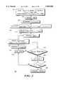
- FIG. 2there is shown a flowchart representing a battery charging method 200 in accordance with the present invention.
- the battery packcan now be charged such that the internal battery cell voltage is maintained at the rated voltage.
- the net effectis that the internal cell can now be charged to its rated voltage and also that the cell can now be charged faster.
- the charging methodbegins at step 202 by storing the rated cell voltage value (Vcell) and the rated minimum and maximum charge current values (Imin, Imax), and characteristic battery circuitry impedance information versus temperature for a given battery type into the memory, such as an EPROM, of the battery.
- the battery pack temperatureis measured by the charger at step 204.
- the battery pack circuitry impedanceis determined by the charger at step 206 based on the measured temperature and the stored impedance characteristics of step 202.
- This battery pack circuit impedanceincludes, but is not limited to, such circuitry as the flex, FETs, polyswitch, and any other associated impedances in the charge path but does not include the battery's internal cell impedance.
- an optimum pack voltage thresholdis determined at step 208 with the following calculation:
- Vcellis the rated internal cell voltage
- Imaxis the maximum rated charge current
- Zcircuitis the battery pack circuitry impedance determined in step 206.
- Step 210proceeds to begin charging the battery with current (I) initially set to the maximum rated charge current (Imax).
- the chargermeasures the battery pack voltage (across B+/B-terminals).
- the measured battery pack voltageis compared to the calculated optimum pack voltage. If the measured pack voltage is less than the calculated optimum pack voltage at step 214, then charge routine re-measures the temperature of the battery pack at step 216 (read temp) and updates the battery pack circuit impedance value (Zcircuit) at step 218, and then updates the optimum battery pack voltage at step 220 using the updated Zcircuit value.
- the charge routinereturns to step 212 and repeats the sequence of steps 212 through 220 until the measured battery pack voltage meets or exceeds the continuously updated optimized battery pack voltage at step 214.
- the charge currentbegins to cut back by a predetermined amount at step 222.
- the reduced charge currentis compared to a minimum threshold, preferably the minimum charge current stored in the battery (Imin). If the charge current is greater than the minimum charge threshold then the routine returns back to the step of re-measuring the temperature at step 216 to repeat the sequence of updating the battery circuit impedance and further updating the optimum pack voltage, this time with the reduced charge current.
- the optimum pack voltage valueis adapted to compensate not only for variations in the battery circuitry impedance caused by temperature, but also to the variations in the charge current as the charge current is being cut back.
- a lithium battery pack having an average capacity of 950 mAH with a rated charge current (Icharge) of 1 Amp, and a rated internal cell voltage (Vcell) of 4.2 voltsmight include battery charge circuitry including a flex impedance of 72 milliohms, a FET impedance of 52 milliohms, and a polyswitch impedance of 45 milliohms. Therefore:
- the battery packwill continue to be charged with the rated charge and the optimum pack voltage is updated to compensate for variations in Zcircuit over temperature. Once the measured pack voltage exceeds the updated optimum pack voltage, the current will begin and continue to cut back. Again, the optimum pack voltage value is updated to compensate for impedance variations caused by temperature as well as lower current. Once the minimum charge current threshold is reached the charge is terminated.
- the charging routine described by the inventionallows the internal cells themselves to be substantially closer to the rated 4.2 volts without being overcharged as well as achieving a reduced charge time.
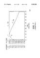
- FIGS. 3 and 4shows charging 300 and discharging 400 curves of a 8 millimeter lithium ion battery using a prior art charging technique.
- Graph 300shows the battery being charged to 4.2 volts with the prior art technique of constant current, constant voltage.
- Designator 302depicts voltage while designator 304 depicts current.
- the battery packwas charged with a current (I) of 1 Amp, and a rated internal cell voltage (Vcell) value of 4.2 volts.
- the charge durationwas 2 hours, 25 minutes, and 44 seconds.
- Graph 400shows the same battery being discharged with a constant 1 Amp discharge, the battery's capacity was measured to be 944 mAH.
- Designator 402depicts voltage while designator 404 depicts current. The discharge time and capacity depicted in graphs 300, 400 are typical for this type of cell.
- FIGS. 5 and 6show charging and discharging curves 500, 600 respectively for the same battery charged in accordance with the present invention.
- Graph 500shows the voltage 502 and the current 504 for the battery pack being charged to the optimized 4.372 volts with a 1 Amp. The charge current 504 is then cut back in accordance with the invention and the battery pack voltage 502 drops off somewhat accordingly. The internal battery cell voltage, however, would be maintained at approximately the 4.2 volt limit. The charge duration for this battery was 1 hour, 54 minutes, 6 seconds.
- FIGS. 7, 8, 9, and 10depict this increase in charge capacity.
- FIGS. 7 and 8show one hour charge and one hour discharge curves 700, 800 respectively for the battery charged using the prior art charging technique.
- Graph 700shows the voltage 702 and current 704 for the battery over a 1 hour time frame.
- Graph 800shows the voltage 802 and the current 804 while the battery was discharged with a constant 1 Amp load. The battery's capacity measured 751 mAH or 79 percent.
- FIGS. 9 and 10show one hour charge and discharge curves 900, 1000 respectively for the same battery which was charged in accordance with the charging technique of the present invention.
- Graph 900the voltage 902 and the current 904 over a 1 hour time frame.
- Graph 1000shows the voltage 1002 and current 1004 for the same battery being discharged with a constant 1 amp load. The battery's capacity measured 841 mAH or 89 percent.
- the charging method described by the inventionis beneficial to charging systems which utilize characteristic constant current/constant voltage charging, such as lithium battery charging systems. By compensating the optimum pack value for the extra impedances in the battery pack, the internal cell voltage can now be maintained closer to its rated voltage.
- the implementation of the charge routine described by the inventionis accomplished without additional circuitry to either the battery or charger making its implementation advantageous in terms of manufacturing and cost.
Landscapes
- Engineering & Computer Science (AREA)
- Power Engineering (AREA)
- Secondary Cells (AREA)
- Charge And Discharge Circuits For Batteries Or The Like (AREA)
Abstract
Description
Voptimum=Vcell+(Imax×Zcircuit),
Zcircuit=75+52+45=172 milliohms,
Voptimum=4.2 V+(1.0 A)×(172 mΩ)=4.372 V
Claims (10)
Priority Applications (1)
| Application Number | Priority Date | Filing Date | Title |
|---|---|---|---|
| US09/122,707US5969508A (en) | 1998-07-27 | 1998-07-27 | Battery charging method using battery circuitry impedence measurement to determine optimum charging voltage |
Applications Claiming Priority (1)
| Application Number | Priority Date | Filing Date | Title |
|---|---|---|---|
| US09/122,707US5969508A (en) | 1998-07-27 | 1998-07-27 | Battery charging method using battery circuitry impedence measurement to determine optimum charging voltage |
Publications (1)
| Publication Number | Publication Date |
|---|---|
| US5969508Atrue US5969508A (en) | 1999-10-19 |
Family
ID=22404270
Family Applications (1)
| Application Number | Title | Priority Date | Filing Date |
|---|---|---|---|
| US09/122,707Expired - LifetimeUS5969508A (en) | 1998-07-27 | 1998-07-27 | Battery charging method using battery circuitry impedence measurement to determine optimum charging voltage |
Country Status (1)
| Country | Link |
|---|---|
| US (1) | US5969508A (en) |
Cited By (37)
| Publication number | Priority date | Publication date | Assignee | Title |
|---|---|---|---|---|
| US6169384B1 (en)* | 1999-04-19 | 2001-01-02 | Packard Bell Nec Inc. | Power source system for portable electronic devices |
| US6313609B1 (en) | 2000-10-19 | 2001-11-06 | Gregory D. Brink | Determining battery capacity using one or more applications of a constant power load |
| US6326770B1 (en)* | 2000-09-05 | 2001-12-04 | Motorola, Inc. | Battery charging system apparatus and technique |
| US6479968B1 (en)* | 2000-09-27 | 2002-11-12 | Motorola, Inc. | Method of charging a battery utilizing dynamic cable compensation |
| US20040232890A1 (en)* | 2002-01-17 | 2004-11-25 | Kyoichi Ariga | System for controlling charging of secondary battery |
| US20050224552A1 (en)* | 2004-04-02 | 2005-10-13 | Alan Berry | Flywheel configuration for a power tool |
| US20050264263A1 (en)* | 2004-06-01 | 2005-12-01 | Tsenter Boris I | Methods of charging, equalizing, and controlling Li-based batteries |
| US7126310B1 (en) | 2001-04-20 | 2006-10-24 | Abiomed, Inc. | Apparatus and method for balanced charging of a multiple-cell battery pack |
| US20060259098A1 (en)* | 2004-04-12 | 2006-11-16 | Erickson John H | Systems and methods for use in pulse generation |
| US7138595B2 (en) | 2004-04-02 | 2006-11-21 | Black & Decker Inc. | Trigger configuration for a power tool |
| US7165305B2 (en) | 2004-04-02 | 2007-01-23 | Black & Decker Inc. | Activation arm assembly method |
| US20070046262A1 (en)* | 2005-08-25 | 2007-03-01 | Canon Kabushiki Kaisha | Battery-powered apparatus, method of controlling the apparatus, program for implementing the method, and storage medium storing the program |
| WO2006128037A3 (en)* | 2005-05-26 | 2007-03-29 | Advanced Neuromodulation Sys | Systems and methods for use in pulse generation |
| US20070075682A1 (en)* | 2005-09-30 | 2007-04-05 | Guang Huang T | Rapid charge lithium ion battery charger |
| US7204403B2 (en) | 2004-04-02 | 2007-04-17 | Black & Decker Inc. | Activation arm configuration for a power tool |
| US7322506B2 (en) | 2004-04-02 | 2008-01-29 | Black & Decker Inc. | Electric driving tool with driver propelled by flywheel inertia |
| US7331403B2 (en) | 2004-04-02 | 2008-02-19 | Black & Decker Inc. | Lock-out for activation arm mechanism in a power tool |
| US20080278111A1 (en)* | 2007-05-11 | 2008-11-13 | Commissariat A L'energie Atomique | Method for charging a battery of an autonomous system |
| US20090048643A1 (en)* | 2004-04-12 | 2009-02-19 | Erickson John H | Method for providing multiple voltage levels during pulse generation and implantable pulse generating employing the same |
| US7503401B2 (en) | 2004-04-02 | 2009-03-17 | Black & Decker Inc. | Solenoid positioning methodology |
| US7556184B2 (en) | 2007-06-11 | 2009-07-07 | Black & Decker Inc. | Profile lifter for a nailer |
| US7686199B2 (en) | 2004-04-02 | 2010-03-30 | Black & Decker Inc. | Lower bumper configuration for a power tool |
| US7726536B2 (en) | 2004-04-02 | 2010-06-01 | Black & Decker Inc. | Upper bumper configuration for a power tool |
| US20100207571A1 (en)* | 2009-02-19 | 2010-08-19 | SunCore Corporation | Solar chargeable battery for portable devices |
| US7789169B2 (en) | 2004-04-02 | 2010-09-07 | Black & Decker Inc. | Driver configuration for a power tool |
| US7975893B2 (en) | 2004-04-02 | 2011-07-12 | Black & Decker Inc. | Return cord assembly for a power tool |
| US20110199040A1 (en)* | 2010-02-12 | 2011-08-18 | Suncore, Inc. | Stand alone solar battery charger |
| US8123099B2 (en) | 2004-04-02 | 2012-02-28 | Black & Decker Inc. | Cam and clutch configuration for a power tool |
| FR2970822A1 (en)* | 2011-01-26 | 2012-07-27 | Peugeot Citroen Automobiles Sa | DEVICE FOR MONITORING THE RECHARGING OF AN ELECTRIC BATTERY OF A SYSTEM, BY ESTIMATING IMPEDANCE AND / OR PASSING NON-LINEAR EFFECT (S) BEFORE A CHARGER |
| US8231039B2 (en) | 2004-04-02 | 2012-07-31 | Black & Decker Inc. | Structural backbone/motor mount for a power tool |
| US8302833B2 (en) | 2004-04-02 | 2012-11-06 | Black & Decker Inc. | Power take off for cordless nailer |
| US20130093385A1 (en)* | 2011-10-14 | 2013-04-18 | Research In Motion Limited | Mode changing power control |
| US20150030891A1 (en)* | 2012-02-21 | 2015-01-29 | Research Foundation Of The City University Of New York | Alkaline Battery Operational Methodology |
| US9397516B2 (en) | 2010-10-22 | 2016-07-19 | Nucleus Scientific, Inc. | Apparatus and method for rapidly charging batteries |
| US10237830B1 (en) | 2017-08-31 | 2019-03-19 | Google Llc | Dynamic battery power management |
| US10882172B2 (en) | 2004-04-02 | 2021-01-05 | Black & Decker, Inc. | Powered hand-held fastening tool |
| US11345254B2 (en)* | 2019-12-19 | 2022-05-31 | Ford Global Technologies, Llc | EKF state relay strategy in battery online identification |
Citations (4)
| Publication number | Priority date | Publication date | Assignee | Title |
|---|---|---|---|---|
| US5646508A (en)* | 1994-11-10 | 1997-07-08 | Duracell, Inc. | Battery pack having a processor controlled battery operating system |
| US5684387A (en)* | 1996-08-15 | 1997-11-04 | Motorola, Inc. | Voltage cutoff compensation method for a battery in a charger |
| US5905358A (en)* | 1997-10-24 | 1999-05-18 | Motorola, Inc. | Method for distinguishing a standard battery from an ultrafast battery and charging same |
| US5912547A (en)* | 1994-09-13 | 1999-06-15 | Intermec Ip Corp. | Battery charging method and apparatus with thermal mass equalization |
- 1998
- 1998-07-27USUS09/122,707patent/US5969508A/ennot_activeExpired - Lifetime
Patent Citations (4)
| Publication number | Priority date | Publication date | Assignee | Title |
|---|---|---|---|---|
| US5912547A (en)* | 1994-09-13 | 1999-06-15 | Intermec Ip Corp. | Battery charging method and apparatus with thermal mass equalization |
| US5646508A (en)* | 1994-11-10 | 1997-07-08 | Duracell, Inc. | Battery pack having a processor controlled battery operating system |
| US5684387A (en)* | 1996-08-15 | 1997-11-04 | Motorola, Inc. | Voltage cutoff compensation method for a battery in a charger |
| US5905358A (en)* | 1997-10-24 | 1999-05-18 | Motorola, Inc. | Method for distinguishing a standard battery from an ultrafast battery and charging same |
Cited By (61)
| Publication number | Priority date | Publication date | Assignee | Title |
|---|---|---|---|---|
| US6169384B1 (en)* | 1999-04-19 | 2001-01-02 | Packard Bell Nec Inc. | Power source system for portable electronic devices |
| US6326770B1 (en)* | 2000-09-05 | 2001-12-04 | Motorola, Inc. | Battery charging system apparatus and technique |
| US6479968B1 (en)* | 2000-09-27 | 2002-11-12 | Motorola, Inc. | Method of charging a battery utilizing dynamic cable compensation |
| US6313609B1 (en) | 2000-10-19 | 2001-11-06 | Gregory D. Brink | Determining battery capacity using one or more applications of a constant power load |
| US7126310B1 (en) | 2001-04-20 | 2006-10-24 | Abiomed, Inc. | Apparatus and method for balanced charging of a multiple-cell battery pack |
| US20040232890A1 (en)* | 2002-01-17 | 2004-11-25 | Kyoichi Ariga | System for controlling charging of secondary battery |
| US7726536B2 (en) | 2004-04-02 | 2010-06-01 | Black & Decker Inc. | Upper bumper configuration for a power tool |
| US7503401B2 (en) | 2004-04-02 | 2009-03-17 | Black & Decker Inc. | Solenoid positioning methodology |
| US8011549B2 (en) | 2004-04-02 | 2011-09-06 | Black & Decker Inc. | Flywheel configuration for a power tool |
| US7138595B2 (en) | 2004-04-02 | 2006-11-21 | Black & Decker Inc. | Trigger configuration for a power tool |
| US7165305B2 (en) | 2004-04-02 | 2007-01-23 | Black & Decker Inc. | Activation arm assembly method |
| US8123099B2 (en) | 2004-04-02 | 2012-02-28 | Black & Decker Inc. | Cam and clutch configuration for a power tool |
| US20050224552A1 (en)* | 2004-04-02 | 2005-10-13 | Alan Berry | Flywheel configuration for a power tool |
| US7686199B2 (en) | 2004-04-02 | 2010-03-30 | Black & Decker Inc. | Lower bumper configuration for a power tool |
| US7204403B2 (en) | 2004-04-02 | 2007-04-17 | Black & Decker Inc. | Activation arm configuration for a power tool |
| US11090791B2 (en) | 2004-04-02 | 2021-08-17 | Black & Decker Inc. | Powered hand-held fastening tool |
| US7322506B2 (en) | 2004-04-02 | 2008-01-29 | Black & Decker Inc. | Electric driving tool with driver propelled by flywheel inertia |
| US10882172B2 (en) | 2004-04-02 | 2021-01-05 | Black & Decker, Inc. | Powered hand-held fastening tool |
| US7331403B2 (en) | 2004-04-02 | 2008-02-19 | Black & Decker Inc. | Lock-out for activation arm mechanism in a power tool |
| US10272554B2 (en) | 2004-04-02 | 2019-04-30 | Black & Decker Inc. | Powered hand-held fastening tool |
| US8231039B2 (en) | 2004-04-02 | 2012-07-31 | Black & Decker Inc. | Structural backbone/motor mount for a power tool |
| US7975893B2 (en) | 2004-04-02 | 2011-07-12 | Black & Decker Inc. | Return cord assembly for a power tool |
| US8302833B2 (en) | 2004-04-02 | 2012-11-06 | Black & Decker Inc. | Power take off for cordless nailer |
| US9486905B2 (en) | 2004-04-02 | 2016-11-08 | Black & Decker Inc. | Driving tool with controller having microswitch for controlling operation of motor |
| US7789169B2 (en) | 2004-04-02 | 2010-09-07 | Black & Decker Inc. | Driver configuration for a power tool |
| US7571007B2 (en) | 2004-04-12 | 2009-08-04 | Advanced Neuromodulation Systems, Inc. | Systems and methods for use in pulse generation |
| US9533164B2 (en) | 2004-04-12 | 2017-01-03 | Advanced Neuromodulation Systems, Inc. | Method for providing multiple voltage levels during pulse generation and implantable pulse generating employing the same |
| US20090048643A1 (en)* | 2004-04-12 | 2009-02-19 | Erickson John H | Method for providing multiple voltage levels during pulse generation and implantable pulse generating employing the same |
| US20060259098A1 (en)* | 2004-04-12 | 2006-11-16 | Erickson John H | Systems and methods for use in pulse generation |
| US20050264263A1 (en)* | 2004-06-01 | 2005-12-01 | Tsenter Boris I | Methods of charging, equalizing, and controlling Li-based batteries |
| EP2465577A1 (en)* | 2005-05-26 | 2012-06-20 | Advanced Neuromodulation Systems, Inc. | Systems and methods for use in pulse generation |
| WO2006128037A3 (en)* | 2005-05-26 | 2007-03-29 | Advanced Neuromodulation Sys | Systems and methods for use in pulse generation |
| EP2465576A1 (en)* | 2005-05-26 | 2012-06-20 | Advanced Neuromodulation Systems, Inc. | Systems and methods for use in pulse generation |
| US20100289455A1 (en)* | 2005-08-25 | 2010-11-18 | Canon Kabushiki Kaisha | Battery-powered apparatus, method of controlling the apparatus, program for implementing the method, and storage medium storing the program |
| US20070046262A1 (en)* | 2005-08-25 | 2007-03-01 | Canon Kabushiki Kaisha | Battery-powered apparatus, method of controlling the apparatus, program for implementing the method, and storage medium storing the program |
| US7786700B2 (en)* | 2005-08-25 | 2010-08-31 | Canon Kabushiki Kaisha | Battery-powered apparatus, method of controlling the apparatus, program for implementing the method, and storage medium storing the program |
| US7863864B2 (en) | 2005-08-25 | 2011-01-04 | Canon Kabushiki Kaisha | Battery-powered apparatus, method of controlling the apparatus, program for implementing the method, and storage medium storing the program |
| US20070075682A1 (en)* | 2005-09-30 | 2007-04-05 | Guang Huang T | Rapid charge lithium ion battery charger |
| US20080024090A1 (en)* | 2005-09-30 | 2008-01-31 | Guang Huang T | Rapid charge lithium ion battery charger |
| US7898220B2 (en) | 2005-09-30 | 2011-03-01 | Icc-Nexergy, Inc. | Rapid charge lithium ion battery charger |
| US20080012533A1 (en)* | 2005-09-30 | 2008-01-17 | Guang Huang T | Rapid charge lithium ion battery charger |
| WO2007040948A3 (en)* | 2005-09-30 | 2009-04-23 | Internat Components Corp | Rapid charge lithium ion battery charger |
| US7683574B2 (en) | 2005-09-30 | 2010-03-23 | International Components Corporation | Rapid charge lithium ion battery charger |
| US7598709B2 (en) | 2005-09-30 | 2009-10-06 | International Components Corporation | Rapid charge lithium ion battery charger |
| US20100033137A1 (en)* | 2005-09-30 | 2010-02-11 | Huang Tai Guang | Rapid charge lithium ion battery charger |
| US7626362B2 (en) | 2005-09-30 | 2009-12-01 | International Components Corporation | Rapid charge lithium ion battery charger |
| US20080278111A1 (en)* | 2007-05-11 | 2008-11-13 | Commissariat A L'energie Atomique | Method for charging a battery of an autonomous system |
| US7556184B2 (en) | 2007-06-11 | 2009-07-07 | Black & Decker Inc. | Profile lifter for a nailer |
| US20100207571A1 (en)* | 2009-02-19 | 2010-08-19 | SunCore Corporation | Solar chargeable battery for portable devices |
| US8319470B2 (en) | 2010-02-12 | 2012-11-27 | Suncore, Inc. | Stand alone solar battery charger |
| US20110199040A1 (en)* | 2010-02-12 | 2011-08-18 | Suncore, Inc. | Stand alone solar battery charger |
| US9397516B2 (en) | 2010-10-22 | 2016-07-19 | Nucleus Scientific, Inc. | Apparatus and method for rapidly charging batteries |
| FR2970822A1 (en)* | 2011-01-26 | 2012-07-27 | Peugeot Citroen Automobiles Sa | DEVICE FOR MONITORING THE RECHARGING OF AN ELECTRIC BATTERY OF A SYSTEM, BY ESTIMATING IMPEDANCE AND / OR PASSING NON-LINEAR EFFECT (S) BEFORE A CHARGER |
| WO2012101343A3 (en)* | 2011-01-26 | 2013-08-08 | Peugeot Citroën Automobiles SA | Device for controlling the charging of an electrical battery of a system, by estimating parasite impedance and/or non-linear effect upstream of a charger |
| US20130093385A1 (en)* | 2011-10-14 | 2013-04-18 | Research In Motion Limited | Mode changing power control |
| CN104662730A (en)* | 2012-02-21 | 2015-05-27 | 纽约城市大学研究基金会 | Alkaline battery operational methodology |
| US20150030891A1 (en)* | 2012-02-21 | 2015-01-29 | Research Foundation Of The City University Of New York | Alkaline Battery Operational Methodology |
| US9419289B2 (en)* | 2012-02-21 | 2016-08-16 | Research Foundation Of The City University Of New York | Alkaline battery operational methodology |
| US10237830B1 (en) | 2017-08-31 | 2019-03-19 | Google Llc | Dynamic battery power management |
| US10945213B2 (en) | 2017-08-31 | 2021-03-09 | Google Llc | Dynamic battery power management |
| US11345254B2 (en)* | 2019-12-19 | 2022-05-31 | Ford Global Technologies, Llc | EKF state relay strategy in battery online identification |
Similar Documents
| Publication | Publication Date | Title |
|---|---|---|
| US5969508A (en) | Battery charging method using battery circuitry impedence measurement to determine optimum charging voltage | |
| US6204634B1 (en) | Adaptive charging method for lithium-ion battery cells | |
| US6573687B2 (en) | Charging/discharging control method for secondary battery | |
| US8704488B2 (en) | Battery pack and method of controlling the same | |
| JP4388094B2 (en) | Battery pack protection device and battery pack device | |
| US5939864A (en) | Lithium-ion battery charge control method | |
| US5510693A (en) | Method for battery charging | |
| US20090184685A1 (en) | Battery pack and method of charging the same | |
| KR101504804B1 (en) | Apparatus and method for estimating state of secondary battery considering aging | |
| US20020036482A1 (en) | Charging method of rechargeable battery | |
| WO2002045238A2 (en) | Life cycle charging for batteries | |
| CN109655753B (en) | Estimation method of SOC of battery pack | |
| JP5305653B2 (en) | Method for charging a lithium ion storage battery having a negative electrode | |
| JP3915151B2 (en) | Battery pack manufacturing method | |
| JP5508771B2 (en) | Battery pack and battery system | |
| Darwish et al. | Review of battery management systems | |
| CN113991773A (en) | Charging method and related equipment | |
| JPH10304589A (en) | Complementary charging of battery by charging battery with pulse current and keeping it in full-charged state | |
| US6459239B1 (en) | Method and apparatus for recharging batteries in the presence of a load current | |
| US6097176A (en) | Method for managing back-up power source | |
| US20240393399A1 (en) | Low temperature state-of-charge correction for a mixed chemistry battery | |
| US20250192254A1 (en) | Battery management system, battery pack, electric vehicle, and battery management method | |
| CN104079025A (en) | System and method for extending useful life of lithium-ion and batteries of similar type | |
| JP2000150000A (en) | How to manage backup power | |
| KR20170059802A (en) | Secondary battery charging system and method |
Legal Events
| Date | Code | Title | Description |
|---|---|---|---|
| AS | Assignment | Owner name:MOTOROLA, INC., A CORPORATION OF DELAWARE, ILLINOI Free format text:ASSIGNMENT OF ASSIGNORS INTEREST;ASSIGNORS:PATINO, JOSEPH;GEREN, MICHAEL D.;DOUTRE, BARBARA R.;REEL/FRAME:009345/0813;SIGNING DATES FROM 19980723 TO 19980724 | |
| STCF | Information on status: patent grant | Free format text:PATENTED CASE | |
| FPAY | Fee payment | Year of fee payment:4 | |
| REMI | Maintenance fee reminder mailed | ||
| FPAY | Fee payment | Year of fee payment:8 | |
| AS | Assignment | Owner name:MOTOROLA MOBILITY, INC, ILLINOIS Free format text:ASSIGNMENT OF ASSIGNORS INTEREST;ASSIGNOR:MOTOROLA, INC;REEL/FRAME:025673/0558 Effective date:20100731 | |
| FPAY | Fee payment | Year of fee payment:12 | |
| AS | Assignment | Owner name:MOTOROLA MOBILITY LLC, ILLINOIS Free format text:CHANGE OF NAME;ASSIGNOR:MOTOROLA MOBILITY, INC.;REEL/FRAME:029216/0282 Effective date:20120622 | |
| AS | Assignment | Owner name:GOOGLE TECHNOLOGY HOLDINGS LLC, CALIFORNIA Free format text:ASSIGNMENT OF ASSIGNORS INTEREST;ASSIGNOR:MOTOROLA MOBILITY LLC;REEL/FRAME:034423/0001 Effective date:20141028 |