US5968018A - Cell separation device and in-line orifice mixer system - Google Patents
Cell separation device and in-line orifice mixer systemDownload PDFInfo
- Publication number
- US5968018A US5968018AUS08/741,233US74123396AUS5968018AUS 5968018 AUS5968018 AUS 5968018AUS 74123396 AUS74123396 AUS 74123396AUS 5968018 AUS5968018 AUS 5968018A
- Authority
- US
- United States
- Prior art keywords
- orifice
- line mixer
- syringe
- walls
- mixing
- Prior art date
- Legal status (The legal status is an assumption and is not a legal conclusion. Google has not performed a legal analysis and makes no representation as to the accuracy of the status listed.)
- Expired - Lifetime
Links
- 238000000926separation methodMethods0.000titleabstractdescription9
- 239000012530fluidSubstances0.000claimsabstractdescription26
- 239000000203mixtureSubstances0.000claimsabstractdescription23
- 238000000034methodMethods0.000claimsdescription17
- 239000007921spraySubstances0.000claimsdescription9
- 238000007599dischargingMethods0.000claimsdescription4
- 239000000463materialSubstances0.000claimsdescription4
- 239000000443aerosolSubstances0.000claimsdescription3
- 230000003197catalytic effectEffects0.000claimsdescription3
- 238000006116polymerization reactionMethods0.000claimsdescription2
- 230000000977initiatory effectEffects0.000claims1
- 238000005119centrifugationMethods0.000abstractdescription18
- 239000008280bloodSubstances0.000abstractdescription12
- 210000004369bloodAnatomy0.000abstractdescription12
- 239000008240homogeneous mixtureSubstances0.000abstract1
- 210000004027cellAnatomy0.000description22
- 238000007906compressionMethods0.000description4
- 230000009977dual effectEffects0.000description4
- 230000004888barrier functionEffects0.000description3
- 238000011109contaminationMethods0.000description3
- 230000008878couplingEffects0.000description3
- 238000010168coupling processMethods0.000description3
- 238000005859coupling reactionMethods0.000description3
- 239000000565sealantSubstances0.000description3
- 239000000126substanceSubstances0.000description3
- 239000003106tissue adhesiveSubstances0.000description3
- 239000002202Polyethylene glycolSubstances0.000description2
- 239000003146anticoagulant agentSubstances0.000description2
- 229940127219anticoagulant drugDrugs0.000description2
- 238000005345coagulationMethods0.000description2
- 230000015271coagulationEffects0.000description2
- 229920001436collagenPolymers0.000description2
- 230000007423decreaseEffects0.000description2
- 230000013011matingEffects0.000description2
- 230000007246mechanismEffects0.000description2
- 229920001223polyethylene glycolPolymers0.000description2
- 230000008569processEffects0.000description2
- 238000007789sealingMethods0.000description2
- 239000000243solutionSubstances0.000description2
- BHPQYMZQTOCNFJ-UHFFFAOYSA-NCalcium cationChemical compound[Ca+2]BHPQYMZQTOCNFJ-UHFFFAOYSA-N0.000description1
- 206010008164Cerebrospinal fluid leakageDiseases0.000description1
- 102000008186CollagenHuman genes0.000description1
- 108010035532CollagenProteins0.000description1
- 239000004971Cross linkerSubstances0.000description1
- KCXVZYZYPLLWCC-UHFFFAOYSA-NEDTAChemical compoundOC(=O)CN(CC(O)=O)CCN(CC(O)=O)CC(O)=OKCXVZYZYPLLWCC-UHFFFAOYSA-N0.000description1
- HTTJABKRGRZYRN-UHFFFAOYSA-NHeparinChemical compoundOC1C(NC(=O)C)C(O)OC(COS(O)(=O)=O)C1OC1C(OS(O)(=O)=O)C(O)C(OC2C(C(OS(O)(=O)=O)C(OC3C(C(O)C(O)C(O3)C(O)=O)OS(O)(=O)=O)C(CO)O2)NS(O)(=O)=O)C(C(O)=O)O1HTTJABKRGRZYRN-UHFFFAOYSA-N0.000description1
- 108090000190ThrombinProteins0.000description1
- 206010052428WoundDiseases0.000description1
- 208000027418Wounds and injuryDiseases0.000description1
- 239000000853adhesiveSubstances0.000description1
- 230000001070adhesive effectEffects0.000description1
- 239000003242anti bacterial agentSubstances0.000description1
- 229940088710antibiotic agentDrugs0.000description1
- 238000000889atomisationMethods0.000description1
- 239000013060biological fluidSubstances0.000description1
- 239000012620biological materialSubstances0.000description1
- 230000000740bleeding effectEffects0.000description1
- 229910001424calcium ionInorganic materials0.000description1
- 239000003054catalystSubstances0.000description1
- 230000005465channelingEffects0.000description1
- 239000002131composite materialSubstances0.000description1
- 230000006835compressionEffects0.000description1
- 239000003814drugSubstances0.000description1
- 230000000694effectsEffects0.000description1
- 230000009969flowable effectEffects0.000description1
- 239000003102growth factorSubstances0.000description1
- 229960002897heparinDrugs0.000description1
- 229920000669heparinPolymers0.000description1
- 208000015181infectious diseaseDiseases0.000description1
- 238000001746injection mouldingMethods0.000description1
- 238000012986modificationMethods0.000description1
- 230000004048modificationEffects0.000description1
- 210000000056organAnatomy0.000description1
- 239000004033plasticSubstances0.000description1
- 229920003023plasticPolymers0.000description1
- 239000003805procoagulantSubstances0.000description1
- 239000012460protein solutionSubstances0.000description1
- NLJMYIDDQXHKNR-UHFFFAOYSA-Ksodium citrateChemical compoundO.O.[Na+].[Na+].[Na+].[O-]C(=O)CC(O)(CC([O-])=O)C([O-])=ONLJMYIDDQXHKNR-UHFFFAOYSA-K0.000description1
- 239000001509sodium citrateSubstances0.000description1
- 229910001220stainless steelInorganic materials0.000description1
- 239000010935stainless steelSubstances0.000description1
- 230000001954sterilising effectEffects0.000description1
- 238000004659sterilization and disinfectionMethods0.000description1
- 229940124597therapeutic agentDrugs0.000description1
- 230000001225therapeutic effectEffects0.000description1
- 229960004072thrombinDrugs0.000description1
- 210000001519tissueAnatomy0.000description1
Images


Classifications
- B—PERFORMING OPERATIONS; TRANSPORTING
- B01—PHYSICAL OR CHEMICAL PROCESSES OR APPARATUS IN GENERAL
- B01D—SEPARATION
- B01D21/00—Separation of suspended solid particles from liquids by sedimentation
- B01D21/26—Separation of sediment aided by centrifugal force or centripetal force
- B01D21/262—Separation of sediment aided by centrifugal force or centripetal force by using a centrifuge
- B—PERFORMING OPERATIONS; TRANSPORTING
- B01—PHYSICAL OR CHEMICAL PROCESSES OR APPARATUS IN GENERAL
- B01D—SEPARATION
- B01D21/00—Separation of suspended solid particles from liquids by sedimentation
- B01D21/24—Feed or discharge mechanisms for settling tanks
- B01D21/245—Discharge mechanisms for the sediments
- B—PERFORMING OPERATIONS; TRANSPORTING
- B01—PHYSICAL OR CHEMICAL PROCESSES OR APPARATUS IN GENERAL
- B01D—SEPARATION
- B01D21/00—Separation of suspended solid particles from liquids by sedimentation
- B01D21/26—Separation of sediment aided by centrifugal force or centripetal force
- B—PERFORMING OPERATIONS; TRANSPORTING
- B01—PHYSICAL OR CHEMICAL PROCESSES OR APPARATUS IN GENERAL
- B01F—MIXING, e.g. DISSOLVING, EMULSIFYING OR DISPERSING
- B01F25/00—Flow mixers; Mixers for falling materials, e.g. solid particles
- B01F25/40—Static mixers
- B01F25/42—Static mixers in which the mixing is affected by moving the components jointly in changing directions, e.g. in tubes provided with baffles or obstructions
- B01F25/421—Static mixers in which the mixing is affected by moving the components jointly in changing directions, e.g. in tubes provided with baffles or obstructions by moving the components in a convoluted or labyrinthine path
- B01F25/423—Static mixers in which the mixing is affected by moving the components jointly in changing directions, e.g. in tubes provided with baffles or obstructions by moving the components in a convoluted or labyrinthine path by means of elements placed in the receptacle for moving or guiding the components
- B01F25/4233—Static mixers in which the mixing is affected by moving the components jointly in changing directions, e.g. in tubes provided with baffles or obstructions by moving the components in a convoluted or labyrinthine path by means of elements placed in the receptacle for moving or guiding the components using plates with holes, the holes being displaced from one plate to the next one to force the flow to make a bending movement
- B—PERFORMING OPERATIONS; TRANSPORTING
- B01—PHYSICAL OR CHEMICAL PROCESSES OR APPARATUS IN GENERAL
- B01F—MIXING, e.g. DISSOLVING, EMULSIFYING OR DISPERSING
- B01F25/00—Flow mixers; Mixers for falling materials, e.g. solid particles
- B01F25/40—Static mixers
- B01F25/45—Mixers in which the materials to be mixed are pressed together through orifices or interstitial spaces, e.g. between beads
- B01F25/452—Mixers in which the materials to be mixed are pressed together through orifices or interstitial spaces, e.g. between beads characterised by elements provided with orifices or interstitial spaces
- B01F25/4521—Mixers in which the materials to be mixed are pressed together through orifices or interstitial spaces, e.g. between beads characterised by elements provided with orifices or interstitial spaces the components being pressed through orifices in elements, e.g. flat plates or cylinders, which obstruct the whole diameter of the tube
- B—PERFORMING OPERATIONS; TRANSPORTING
- B01—PHYSICAL OR CHEMICAL PROCESSES OR APPARATUS IN GENERAL
- B01L—CHEMICAL OR PHYSICAL LABORATORY APPARATUS FOR GENERAL USE
- B01L3/00—Containers or dishes for laboratory use, e.g. laboratory glassware; Droppers
- B01L3/50—Containers for the purpose of retaining a material to be analysed, e.g. test tubes
- B01L3/502—Containers for the purpose of retaining a material to be analysed, e.g. test tubes with fluid transport, e.g. in multi-compartment structures
- B01L3/5021—Test tubes specially adapted for centrifugation purposes
- B—PERFORMING OPERATIONS; TRANSPORTING
- B01—PHYSICAL OR CHEMICAL PROCESSES OR APPARATUS IN GENERAL
- B01D—SEPARATION
- B01D2221/00—Applications of separation devices
- B01D2221/10—Separation devices for use in medical, pharmaceutical or laboratory applications, e.g. separating amalgam from dental treatment residues
Definitions
- the present inventiongenerally relates to a syringe-based fluid separation and mixing system, however, various components of the invention may be used apart from the system as described herein. More specifically, the present invention relates to a method and apparatus for centrifugation using a single syringe for obtaining a biological or other fluid sample and separating suspended flocculents therefrom.
- An example of such an applicationis using the syringe to obtain a blood sample and to separate plasma and cells.
- the syringe containing the separated plasmamay be used alone or in a dual syringe apparatus with an in-line orifice mixer system whereby a plurality of components can be homogeneously mixed and then expelled from a single apparatus.
- the process of obtaining a biological or other fluid sample such as blood and the subsequent centrifugation processgenerally requires multiple steps and devices, including the transferring of the sample from the syringe used to obtain the sample to a separate centrifugation syringe. These steps increase the overall inconvenience, costs, and time necessary to perform the procedure by requiring handling by medical personnel and the sterilization and use of multiple devices. In addition, risks of contamination of the sample and/or infection of the medical personnel are increased as the amount of handling and the number of devices used are increased.
- the application of the separation and mixing system described belowuses, merely as an example, blood as the fluid sample.
- separated plasmamay be mixed with a coagulation solution from another syringe into a mixer.
- the resulting multi-component mixturecan be used as a mixed tissue adhesive for seamlessly or seam-supportingly connecting human or animal tissue or organ parts, for sealing wounds, stopping bleeding and the like.
- a very high degree of homogeneity of the multi-component mixtureis desirable and often necessary due to high pressure transients.
- Thorough mixing of sealant componentsis desirable to maximize strength of the polymerized sealant.
- prior art mixersgenerally do not achieve a sufficient level of mixing in a fast enough time, especially where the viscosity ratio between the two components is relatively high.
- a common prior art mixeris a helical mixer whose primary type of flow is a shear flow.
- An example of a similar method for mixing multi-part compositionsis disclosed in U.S. Pat. No. 5,328,462 to Fischer, which utilizes the rotation of a mixer element within a syringe barrel to mix components.
- the mixtureis then discharged from the mixer.
- Most prior art and commercial pressure nozzlesare of the swirl-type that must first produce a centrifugal velocity on the mixture immediately prior to its being discharged from the exit orifice.
- the prior art helical mixeraccomplishes this by forcing the mixture into a swirl chamber, sending the mixture through spiral channels, and imparting a circular motion superimposed onto the axial velocity of the mixture.
- a helical mixer or a separate swirling mechanismmust be used to effect the swirl-type method of discharging the mixture.
- the separation and mixing system of the present inventionis described herein in terms of utilizing blood as the fluid sample.
- other biological and non-biological fluid samplesmay readily be used in the separation and mixing system as will be apparent to those skilled in the art.
- the centrifugation syringe and in-line orifice mixer system of the present inventioncomprises a single apparatus for blood withdrawal and cell separation and a second apparatus for a more homogeneous mixing of a multi-component substance.
- a standard syringepreferably containing an anticoagulant is used to withdraw blood and the needle is removed from the syringe.
- the syringeis then fitted into a cell separator and placed into a centrifuge and centrifuged. After centrifugation, the separated plasma remains in the syringe with the syringe serving as a source of plasma in the in-line orifice mixer system.
- the orifice mixer system of the present inventioncomprises a syringe assembly which accommodates one or more syringes, each containing a source for a component of the multi-component mixture.
- the syringe assemblyis attached to a manifold such as a Y connector which is in turn attached to the in-line orifice mixer and nozzle.
- a medical personnelcan simultaneously force a protein solution from one syringe and a coagulation solution from another syringe into the in-line orifice mixer.
- a homogeneously mixed multi-component substancesuch as a tissue adhesive or biological sealant would then exit the orifice mixer and nozzle.
- the in-line orifice mixercomprises a plurality of orifice plates each providing one or more orifices.
- the orifice mixeris advantageous in that it generates a high extensional and low rotational fluid flow and subjects the fluid to continual reversals in the extension direction resulting in repeated alternating extensional and compressional flow.
- extensional flowis generated as fluid is accelerated from a relatively large cross-sectional area of a region before an orifice plate through the constriction of an orifice. After passing through an orifice, the fluid experiences a region of compressional flow.
- an extensional flowis created at an orifice entrance and a compressional flow is created at an orifice exit region, resulting in the desirable repeated alternating extension-compression flow.
- an orifice mixercan achieve a more homogeneous mixing of a plurality of components, even where the components have a relatively high viscosity ratio.
- One method of delivering the mixture from the mixer of the present invention to a target areais to eject the mixture through a spray nozzle.
- An alternative to the swirl-type spray nozzleis preferred and an elliptical or noncircular orifice spray nozzle is one such alternative. Due to the nonuniform stresses caused by a noncircular orifice, atomization may occur without a swirl chamber. However, a fan-shaped, conical, rather than circular, spray would result. Thus, if a sheet spray is acceptable, a simple, noncircular exit orifice can be used that would avoid the need of a swirl section.
- One embodiment of the present inventionprovides an elliptical orifice preferably disposed in the center of the last orifice plate of the orifice mixer to serve as an elliptical spray nozzle.
- the last orifice platemay provide multiple orifices and/or orifices of other shapes, such as slots.
- Nonspray methods of delivering the mixture from the mixer to a target areamay also be used, such as by attaching the mixer to one end of a cannula, catheter, or endoscopic device.
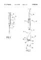
- FIG. 1is a side view of a standard syringe
- FIG. 2is a partial cross-sectional view of a cell separator with the syringe of FIG. 1 before centrifugation, according to a preferred embodiment of the present invention
- FIG. 3is a partial cross-sectional view of the cell separator of FIG. 2 after centrifugation
- FIG. 4depicts an alternative syringe body end
- FIG. 5is a side view of a dual syringe mixer assembly, according to a preferred embodiment of the present invention.
- FIG. 6is a cross-sectional view of an in-line orifice mixer according to the invention.
- FIG. 7is a top view of an orifice plate of the in-line orifice mixer of FIG. 6;
- FIG. 8is a top view of an exit orifice plate of the in-line orifice mixer, according to the preferred embodiment of the present invention.
- FIG. 9is a cross-sectional view of an in-line orifice mixer according to an alternative embodiment of the present invention.
- a standard syringe 10 for use with the present inventionincludes syringe body 12, needle fitting 14, needle 16, handle 18, and plunger 20.
- Syringe 10operates in a known manner to draw a blood sample from a patient.
- syringe 10contains an anticoagulant such as sodium citrate, heparin or EDTA.
- standard syringe 10has been used to draw blood sample B from a patient and the blood sample is contained therein. Needle 16 has been removed and syringe 10 is ready to be placed into cell separator 22 by guiding syringe 10 along syringe guide members 32 and by mating needle fitting 14 with syringe fitting 30.
- tubular body 24may be dimensioned such that syringe guide members 32 are not necessary to guide syringe into cell separator 22.
- Fitting 30is mounted on fixed barrier 28 within tubular body 24. Fitting 30 permits passage of cells through the fixed barrier and into a cell space 33 (see FIG. 3) which is created when moveable plunger 26 of separator 22 moves downward during centrifugation.
- Mating fittings 14 and 30may be selected from commercially available fittings.
- Cell separator 22can be conveniently made by modifying a standard syringe (larger in size than syringe 10) according to the teachings contained herein.
- Syringe handle 18may be removed depending on the requirements of the centrifugation device to be used.
- the syringe-cell separator assemblyis then placed into the centrifugation device and centrifuged. During centrifugation, heavier cells C separate and move through syringe fitting 30 into cell space 33 defined between fixed barrier 28 and movable plunger 26. Simultaneously, both syringe plunger 20 and movable plunger 26 of separator 22 travel by centrifugation force toward stop members 34. Stop members 34 are positioned to control the volume of material which passes through syringe fitting 30 into cell space 33 during centrifugation in order to prevent loss of plasma. The final volume of cell space 33 thus can be controlled as desired to obtain particular results in different applications.
- syringe handle 18may be reattached to syringe 10 to remove plasma P from syringe body 12.
- additional handle 18Amay be attached to fitting 36 on plunge 26 to permit expulsion of the cells through fitting 30.
- cells Ccan remain captive within cell separator 22 which may be discarded with minimal risk of contamination to the medical personnel.
- Standard syringesfrequently include a relatively sharp interior corner 51 in syringe body 12 where diameter of body 12 decreases from that of syringe plunger 20 to that of needle fitting 14.
- the sharpness of interior corner 51can cause a residual deposit of cells R after cell separation by centrifugation, as shown in FIG. 3.
- alternative syringe end 52as shown in FIG. 4, may be used.
- Alternative syringe end 52provides a continuous gradient resulting in a gently curved syringe body wall 54 leading to needle fitting 14 to eliminate the corner where cells may tend to stick.
- syringe 10 containing plasma Pmay be placed in dual syringe applicator 40 by attaching needle fitting 14 to a manifold, such as Y connector 42, at syringe fitting 48a.
- Second component syringe 50can be similarly attached to Y connector 42 at syringe fitting 48b.
- second componentsare calcium ion, thrombin, or other procoagulants.
- second component Sis a thrombin-collagen component which, when properly mixed with plasma P, creates a bio-compatible adhesive.
- Y connector 42connects the outlets of syringe 10 and second component syringe 50 to the inlet 56 of orifice mixer 44.
- Orifice mixer 44As previously discussed, common prior art helical mixers primarily induces shear flow.
- the shear flowis composed of an equal proportion of two basic flow types: elongational or extensional flow and rotational flow. It is the extensional flow component which causes component mixing by effecting fluid droplet deformation and break-up.
- the rotational flow componentinhibits droplet deformation by rotating an extended droplet into a state of compression.
- the two components to be mixedhave a relatively large viscosity ratio, as in the case of the high viscosity collagen composite material and the low viscosity plasma
- use of a shear flowmay be ineffective in producing the desirable high level of droplet break-up and mixing. Therefore, in contrast to a shear flow, a flow that is minimally rotational and highly extensional would be more efficient and effective in achieving mixing of components with a high viscosity ratio.
- orifice mixer 44 of the present inventionsimultaneously produces a minimally rotational highly extensional flow as well as a repeated alternating extension-compression flow.
- orifice mixer 44contains a plurality of orifice plates 58, each disposed a distance from one or more adjacent orifice plates.
- orifice mixer 44may be a stainless steel syringe coupling (luer lock design) comprising a tube of inner diameter 4.3 mm and length 7 mm.
- Each orifice plate 58provides one or more orifices 60.
- Orifice plates 58may be plastic with different orifice sizes such as 0.5 mm, 0.75 mm, and 1.0 mm.
- Orifice plates 58may be integrally formed, such as by injection molding, so that orifice plates 58 are interconnected by one or more coupling members (not shown) along edges of orifice plates 58.
- Orifice platesmay then be placed within mixer 44 such that the coupling members are along length of mixer 44.
- Orifice plates 58may also be separately formed.
- a portion-of each orifice plate 58may be integrally formed with a portion of body of mixer 44 such that two or more of the plate-body portions combine to form mixer 44.
- Orifice 60may be located at the center of orifice plate 58 or offset from the center by, for example, 1 mm, depending on plate size. Preferably one or more of the orifices 60 of each orifice plate 58 do not align with the one or more adjacent orifices 60 of the one or more adjacent orifice plates 58. Non-alignment of orifices 60 avoids channeling of the mixture from one orifice to the next. As components P and S are forced through orifice plates 58, components P and S are mixed, resulting in a homogenous mix of tissue adhesive.
- orifice mixer 44may also contain exit nozzle 46.
- Exit nozzle 46contains exit orifice plate 62 with one or more elliptical exit orifice 64.
- a homogeneous mix of components P and Sis forced through exit orifice 64 and exits exit nozzle 46 in an aerosol or near-aerosol form.
- the elliptical shape of the orificeis preferred for use with the orifice plate mixer due to the lack of spiral motion of the mixed fluid.
- Alternative embodiments of exit orifice plate 62(not shown) provides multiple exit orifices and/or exit orifices of other shapes, such as slots.
- orifice mixer 44may be placed at one end of a cannula, catheter, or endoscopic device in order to deliver a homogeneous mix of components P and S from orifice mixer 44 to a target area.
- one or more orifice plates 58are coated with a third component X, and thus orifice mixer 44' can also serve as a source of component.
- component Xwhen the first component is forced from syringe 10 through orifice plates 58, component X, miscible and soluble with component P, is quickly mixed into component P.
- Substances which may be useful as component Xinclude catalysts, crosslinkers such as activated multifunctional polyethylene glycol (PEG), therapeutic agents such as antibiotics and therapeutic growth factors, or other biomaterials that may be suspended or dissolved into a flowable form.
- one or more orifice plates 58can be made of a catalytic material or modified to be catalytic in order to initiate polymerization.
- mixer 44'may be adapted to mate directly with needle fitting 14.
Landscapes
- Chemical & Material Sciences (AREA)
- Chemical Kinetics & Catalysis (AREA)
- Dispersion Chemistry (AREA)
- Health & Medical Sciences (AREA)
- Hematology (AREA)
- General Health & Medical Sciences (AREA)
- Analytical Chemistry (AREA)
- Clinical Laboratory Science (AREA)
- Infusion, Injection, And Reservoir Apparatuses (AREA)
- Measurement Of The Respiration, Hearing Ability, Form, And Blood Characteristics Of Living Organisms (AREA)
- Investigating Or Analysing Biological Materials (AREA)
- Sampling And Sample Adjustment (AREA)
- Surgical Instruments (AREA)
Abstract
Description
Claims (18)
Priority Applications (9)
| Application Number | Priority Date | Filing Date | Title |
|---|---|---|---|
| US08/741,233US5968018A (en) | 1996-10-30 | 1996-10-30 | Cell separation device and in-line orifice mixer system |
| EP97946378AEP0956086A1 (en) | 1996-10-30 | 1997-10-29 | Cell separation device and in-line orifice mixer system |
| JP52075698AJP2001509884A (en) | 1996-10-30 | 1997-10-29 | Cell separation device and in-line orifice mixer system |
| PCT/US1997/019704WO1998018518A1 (en) | 1996-10-30 | 1997-10-29 | Cell separation device and in-line orifice mixer system |
| AU51563/98AAU5156398A (en) | 1996-10-30 | 1997-10-29 | Cell separation device and in-line orifice mixer system |
| CA002270379ACA2270379A1 (en) | 1996-10-30 | 1997-10-29 | Cell separation device and in-line orifice mixer system |
| US09/032,347US6123687A (en) | 1996-10-30 | 1998-02-27 | Cell separation device and metering syringe |
| JP2007223375AJP2008055170A (en) | 1996-10-30 | 2007-08-30 | Cell separation device and in-line orifice mixer system |
| JP2008178539AJP2009034670A (en) | 1996-10-30 | 2008-07-09 | Cell separation device and in-line orifice mixer system |
Applications Claiming Priority (1)
| Application Number | Priority Date | Filing Date | Title |
|---|---|---|---|
| US08/741,233US5968018A (en) | 1996-10-30 | 1996-10-30 | Cell separation device and in-line orifice mixer system |
Related Child Applications (1)
| Application Number | Title | Priority Date | Filing Date |
|---|---|---|---|
| US09/032,347Continuation-In-PartUS6123687A (en) | 1996-10-30 | 1998-02-27 | Cell separation device and metering syringe |
Publications (1)
| Publication Number | Publication Date |
|---|---|
| US5968018Atrue US5968018A (en) | 1999-10-19 |
Family
ID=24979886
Family Applications (1)
| Application Number | Title | Priority Date | Filing Date |
|---|---|---|---|
| US08/741,233Expired - LifetimeUS5968018A (en) | 1996-10-30 | 1996-10-30 | Cell separation device and in-line orifice mixer system |
Country Status (6)
| Country | Link |
|---|---|
| US (1) | US5968018A (en) |
| EP (1) | EP0956086A1 (en) |
| JP (3) | JP2001509884A (en) |
| AU (1) | AU5156398A (en) |
| CA (1) | CA2270379A1 (en) |
| WO (1) | WO1998018518A1 (en) |
Cited By (26)
| Publication number | Priority date | Publication date | Assignee | Title |
|---|---|---|---|---|
| US20040125690A1 (en)* | 2002-12-30 | 2004-07-01 | Sentmanat Martin Lamar | Cascading orifice mixer |
| WO2006039827A1 (en)* | 2004-10-15 | 2006-04-20 | Medmix Systems Ag | Static mixer |
| US20100082015A1 (en)* | 2008-09-30 | 2010-04-01 | Tyco Healthcare Group Lp | Device for Interfacing with Standard Luer Lock Syringes |
| US7766900B2 (en) | 2005-02-21 | 2010-08-03 | Biomet Manufacturing Corp. | Method and apparatus for application of a fluid |
| US20100267539A1 (en)* | 2005-08-10 | 2010-10-21 | The Regents Of The University Of California | Centrifuge with polymerizing energy source |
| US20110049181A1 (en)* | 2008-04-18 | 2011-03-03 | Peter Lutz | Dispensing device, kit containing the device, and method of operating the device |
| EP2384820A1 (en) | 2010-05-04 | 2011-11-09 | Heraeus Medical GmbH | Cartridge system and application tube for such a cartridge system |
| EP2384821A2 (en) | 2010-05-04 | 2011-11-09 | Heraeus Medical GmbH | Cartridge system with pressurised gas cartridge |
| EP2384822A1 (en) | 2010-05-04 | 2011-11-09 | Heraeus Medical GmbH | Cartridge lock and cartridge with such a lock |
| WO2011137971A1 (en) | 2010-05-04 | 2011-11-10 | Heraeus Medical Gmbh | Cartridge system with connected delivery pistons |
| US8182769B2 (en) | 2008-04-04 | 2012-05-22 | Biomet Biologics, Llc | Clean transportation system |
| DE102011119357A1 (en) | 2011-11-25 | 2013-05-29 | Heraeus Medical Gmbh | Multi-component cartridge system with sliding closures in the cartridges |
| US8518272B2 (en) | 2008-04-04 | 2013-08-27 | Biomet Biologics, Llc | Sterile blood separating system |
| US20130231609A1 (en)* | 2005-02-09 | 2013-09-05 | Children's Medical Center Corporation | Device for mixing and delivering fluids for tissue repair |
| DE102012008815A1 (en) | 2012-05-07 | 2013-11-07 | Heraeus Medical Gmbh | Mixing device for multi-component systems |
| US20140148325A1 (en)* | 2010-10-12 | 2014-05-29 | Snu R & Db Foundation | Centrifugation method and centrifugation device |
| US8944296B2 (en) | 2010-05-04 | 2015-02-03 | Heraeus Medical Gmbh | Dispensing device for cartridges |
| US9073081B2 (en) | 2010-05-04 | 2015-07-07 | Heraeus Medical Gmbh | Dispensing device for pasty materials |
| US10751124B2 (en) | 2017-01-05 | 2020-08-25 | Contraline, Inc. | Methods for implanting and reversing stimuli-responsive implants |
| US10786232B2 (en) | 2006-01-25 | 2020-09-29 | The Children's Medical Center Corporation | Methods and procedures for ligament repair |
| US11253391B2 (en) | 2018-11-13 | 2022-02-22 | Contraline, Inc. | Systems and methods for delivering biomaterials |
| US11419961B2 (en)* | 2008-12-18 | 2022-08-23 | Vivex Biologics Group, Inc. | Bone induction system and methods |
| US11826489B2 (en) | 2013-02-01 | 2023-11-28 | The Children's Medical Center Corporation | Collagen scaffolds |
| US11904068B2 (en) | 2015-11-12 | 2024-02-20 | University Of Virginia Patent Foundation | Occlusive implant compositions |
| US12377193B2 (en) | 2016-07-06 | 2025-08-05 | The Children's Medical Center Corporation | Indirect method of articular tissue repair |
| US12383421B2 (en) | 2017-01-05 | 2025-08-12 | Contraline, Inc. | Contraceptive devices |
Families Citing this family (7)
| Publication number | Priority date | Publication date | Assignee | Title |
|---|---|---|---|---|
| US6913934B2 (en)* | 1998-08-13 | 2005-07-05 | Symyx Technologies, Inc. | Apparatus and methods for parallel processing of multiple reaction mixtures |
| US6759014B2 (en) | 2001-01-26 | 2004-07-06 | Symyx Technologies, Inc. | Apparatus and methods for parallel processing of multiple reaction mixtures |
| DE19916430C1 (en)* | 1999-04-12 | 2001-01-18 | Inst Chemo Biosensorik | Apparatus for use in performing receptor ligand and affinity tests |
| EP3428267B1 (en)* | 2006-10-11 | 2023-11-29 | Boehringer Ingelheim Animal Health USA Inc. | Dispersion devices for aggregates |
| US20080267005A1 (en)* | 2007-04-24 | 2008-10-30 | Tyco Healthcare Group Lp | Applicator system and method of use |
| US20170056846A1 (en)* | 2014-05-09 | 2017-03-02 | Dow Global Technologies Llc | Static mixer |
| JP7332572B2 (en)* | 2017-07-13 | 2023-08-23 | ベクトン・ディキンソン・アンド・カンパニー | biofluid collector |
Citations (24)
| Publication number | Priority date | Publication date | Assignee | Title |
|---|---|---|---|---|
| US3586064A (en)* | 1969-09-03 | 1971-06-22 | Metropolitan Pathology Lab Inc | Blood serum collection tube and method of collection |
| US3654925A (en)* | 1969-09-23 | 1972-04-11 | Becton Dickinson Co | Plasma separator system |
| US3746216A (en)* | 1971-09-10 | 1973-07-17 | Us Navy | Fluid mixer-dispenser |
| US3780935A (en)* | 1972-07-10 | 1973-12-25 | Lukacs & Jacoby Ass | Serum separating method |
| US3800947A (en)* | 1971-07-16 | 1974-04-02 | P Smith | Reagent tube and centrifugally operated solid-liquid separating device |
| US4021352A (en)* | 1974-03-30 | 1977-05-03 | Walter Sarstedt Kunststoff-Spritzgusswerk | Filter device for separating blood fractions |
| US4057499A (en)* | 1973-03-09 | 1977-11-08 | Buono Frank S | Apparatus and method for separation of blood |
| US4142668A (en)* | 1976-10-01 | 1979-03-06 | Lee Jae Y | Serum-plasma separator and transfer apparatus |
| US4359049A (en)* | 1980-04-02 | 1982-11-16 | Immuno Aktiengesellschaft Fur Chemisch-Medizinische Produkte | Apparatus for applying a tissue adhesive on the basis of human or animal proteins |
| US4631055A (en)* | 1984-03-29 | 1986-12-23 | Immuno Aktiengesellschaft Fur Chemisch-Medizinische Produkte | Apparatus for applying a tissue adhesive |
| US4735616A (en)* | 1985-06-20 | 1988-04-05 | Immuno Aktiengesellschaft Fur Chemisch-Medizinische Produkte | Arrangement for applying a tissue adhesive |
| US4818386A (en)* | 1987-10-08 | 1989-04-04 | Becton, Dickinson And Company | Device for separating the components of a liquid sample having higher and lower specific gravities |
| US4828716A (en)* | 1987-04-03 | 1989-05-09 | Andronic Devices, Ltd. | Apparatus and method for separating phases of blood |
| US4874368A (en)* | 1988-07-25 | 1989-10-17 | Micromedics, Inc. | Fibrin glue delivery system |
| US4877520A (en)* | 1987-10-08 | 1989-10-31 | Becton, Dickinson And Company | Device for separating the components of a liquid sample having higher and lower specific gravities |
| US4978336A (en)* | 1987-09-29 | 1990-12-18 | Hemaedics, Inc. | Biological syringe system |
| US4979942A (en)* | 1989-10-16 | 1990-12-25 | Johnson & Johnson Medical, Inc. | Two component syringe delivery system |
| US5116315A (en)* | 1989-10-03 | 1992-05-26 | Hemaedics, Inc. | Biological syringe system |
| US5286257A (en)* | 1992-11-18 | 1994-02-15 | Ultradent Products, Inc. | Syringe apparatus with detachable mixing and delivery tip |
| US5328462A (en)* | 1993-09-03 | 1994-07-12 | Ultradent Products, Inc. | Methods and apparatus for mixing and dispensing multi-part compositions |
| US5393674A (en)* | 1990-12-31 | 1995-02-28 | Levine Robert A | Constitutent layer harvesting from a centrifuged sample in a tube |
| US5456885A (en)* | 1993-07-12 | 1995-10-10 | Coleman; Charles M. | Fluid collection, separation and dispensing tube |
| US5464396A (en)* | 1993-10-18 | 1995-11-07 | Immuno Ag | Syringe assembly for the storage and application of a biological multi-component material |
| US5474540A (en)* | 1994-03-25 | 1995-12-12 | Micromedics, Inc. | Fluid separation control attachment for physiologic glue applicator |
Family Cites Families (6)
| Publication number | Priority date | Publication date | Assignee | Title |
|---|---|---|---|---|
| JPS519862A (en)* | 1974-07-15 | 1976-01-26 | Alna Koki Kk | Madowakubuzaino setsudansunhowaridashisochi |
| US4338980A (en)* | 1980-01-14 | 1982-07-13 | Schwebel Paul R | Device for filling medicament injectors |
| US4614440A (en)* | 1985-03-21 | 1986-09-30 | Komax Systems, Inc. | Stacked motionless mixer |
| JPS6274837A (en)* | 1985-09-25 | 1987-04-06 | Chiyoda Kosakusho:Kk | Storage device |
| JPS63242332A (en)* | 1987-03-31 | 1988-10-07 | Nordson Kk | Method and apparatus for mixing, and mixing and emitting or ejecting liquids |
| GB9425642D0 (en)* | 1994-12-20 | 1995-02-22 | Weston Medical Ltd | Filling device |
- 1996
- 1996-10-30USUS08/741,233patent/US5968018A/ennot_activeExpired - Lifetime
- 1997
- 1997-10-29CACA002270379Apatent/CA2270379A1/ennot_activeAbandoned
- 1997-10-29JPJP52075698Apatent/JP2001509884A/enactivePending
- 1997-10-29AUAU51563/98Apatent/AU5156398A/ennot_activeAbandoned
- 1997-10-29EPEP97946378Apatent/EP0956086A1/ennot_activeWithdrawn
- 1997-10-29WOPCT/US1997/019704patent/WO1998018518A1/ennot_activeApplication Discontinuation
- 2007
- 2007-08-30JPJP2007223375Apatent/JP2008055170A/enactivePending
- 2008
- 2008-07-09JPJP2008178539Apatent/JP2009034670A/enactivePending
Patent Citations (25)
| Publication number | Priority date | Publication date | Assignee | Title |
|---|---|---|---|---|
| US3586064A (en)* | 1969-09-03 | 1971-06-22 | Metropolitan Pathology Lab Inc | Blood serum collection tube and method of collection |
| US3654925A (en)* | 1969-09-23 | 1972-04-11 | Becton Dickinson Co | Plasma separator system |
| US3800947A (en)* | 1971-07-16 | 1974-04-02 | P Smith | Reagent tube and centrifugally operated solid-liquid separating device |
| US3746216A (en)* | 1971-09-10 | 1973-07-17 | Us Navy | Fluid mixer-dispenser |
| US3780935A (en)* | 1972-07-10 | 1973-12-25 | Lukacs & Jacoby Ass | Serum separating method |
| US4057499A (en)* | 1973-03-09 | 1977-11-08 | Buono Frank S | Apparatus and method for separation of blood |
| US4021352A (en)* | 1974-03-30 | 1977-05-03 | Walter Sarstedt Kunststoff-Spritzgusswerk | Filter device for separating blood fractions |
| US4142668A (en)* | 1976-10-01 | 1979-03-06 | Lee Jae Y | Serum-plasma separator and transfer apparatus |
| US4359049A (en)* | 1980-04-02 | 1982-11-16 | Immuno Aktiengesellschaft Fur Chemisch-Medizinische Produkte | Apparatus for applying a tissue adhesive on the basis of human or animal proteins |
| US4631055A (en)* | 1984-03-29 | 1986-12-23 | Immuno Aktiengesellschaft Fur Chemisch-Medizinische Produkte | Apparatus for applying a tissue adhesive |
| US4735616A (en)* | 1985-06-20 | 1988-04-05 | Immuno Aktiengesellschaft Fur Chemisch-Medizinische Produkte | Arrangement for applying a tissue adhesive |
| US4828716A (en)* | 1987-04-03 | 1989-05-09 | Andronic Devices, Ltd. | Apparatus and method for separating phases of blood |
| US5308506A (en)* | 1987-04-03 | 1994-05-03 | Mcewen James A | Apparatus and method for separating a sample of blood |
| US4978336A (en)* | 1987-09-29 | 1990-12-18 | Hemaedics, Inc. | Biological syringe system |
| US4877520A (en)* | 1987-10-08 | 1989-10-31 | Becton, Dickinson And Company | Device for separating the components of a liquid sample having higher and lower specific gravities |
| US4818386A (en)* | 1987-10-08 | 1989-04-04 | Becton, Dickinson And Company | Device for separating the components of a liquid sample having higher and lower specific gravities |
| US4874368A (en)* | 1988-07-25 | 1989-10-17 | Micromedics, Inc. | Fibrin glue delivery system |
| US5116315A (en)* | 1989-10-03 | 1992-05-26 | Hemaedics, Inc. | Biological syringe system |
| US4979942A (en)* | 1989-10-16 | 1990-12-25 | Johnson & Johnson Medical, Inc. | Two component syringe delivery system |
| US5393674A (en)* | 1990-12-31 | 1995-02-28 | Levine Robert A | Constitutent layer harvesting from a centrifuged sample in a tube |
| US5286257A (en)* | 1992-11-18 | 1994-02-15 | Ultradent Products, Inc. | Syringe apparatus with detachable mixing and delivery tip |
| US5456885A (en)* | 1993-07-12 | 1995-10-10 | Coleman; Charles M. | Fluid collection, separation and dispensing tube |
| US5328462A (en)* | 1993-09-03 | 1994-07-12 | Ultradent Products, Inc. | Methods and apparatus for mixing and dispensing multi-part compositions |
| US5464396A (en)* | 1993-10-18 | 1995-11-07 | Immuno Ag | Syringe assembly for the storage and application of a biological multi-component material |
| US5474540A (en)* | 1994-03-25 | 1995-12-12 | Micromedics, Inc. | Fluid separation control attachment for physiologic glue applicator |
Cited By (60)
| Publication number | Priority date | Publication date | Assignee | Title |
|---|---|---|---|---|
| US20040125690A1 (en)* | 2002-12-30 | 2004-07-01 | Sentmanat Martin Lamar | Cascading orifice mixer |
| US7033067B2 (en) | 2002-12-30 | 2006-04-25 | The Goodyear Tire & Rubber Company | Cascading orifice mixer |
| WO2006039827A1 (en)* | 2004-10-15 | 2006-04-20 | Medmix Systems Ag | Static mixer |
| US20080056065A1 (en)* | 2004-10-15 | 2008-03-06 | Medmix Systems Ag | Static Mixer |
| CN101056697B (en)* | 2004-10-15 | 2011-10-26 | 药物混合系统股份公司 | Static mixer |
| US20130231609A1 (en)* | 2005-02-09 | 2013-09-05 | Children's Medical Center Corporation | Device for mixing and delivering fluids for tissue repair |
| US7766900B2 (en) | 2005-02-21 | 2010-08-03 | Biomet Manufacturing Corp. | Method and apparatus for application of a fluid |
| US8444620B2 (en) | 2005-02-21 | 2013-05-21 | Biomet Biologics, Llc | Method and apparatus for application of a fluid |
| US9028457B2 (en) | 2005-02-21 | 2015-05-12 | Biomet Biologics, Llc | Method and apparatus for application of a fluid |
| US20100267539A1 (en)* | 2005-08-10 | 2010-10-21 | The Regents Of The University Of California | Centrifuge with polymerizing energy source |
| US8282540B2 (en) | 2005-08-10 | 2012-10-09 | The Regents Of The University Of California | Centrifuge with polymerizing energy source |
| US10786239B2 (en) | 2006-01-25 | 2020-09-29 | The Children's Medical Center Corporation | Methods and procedures for ligament repair |
| US10786238B2 (en) | 2006-01-25 | 2020-09-29 | The Children's Medical Center Corporation | Methods and procedures for ligament repair |
| US10786232B2 (en) | 2006-01-25 | 2020-09-29 | The Children's Medical Center Corporation | Methods and procedures for ligament repair |
| US11076846B2 (en) | 2006-01-25 | 2021-08-03 | The Children's Medical Center Corporation | Methods and procedures for ligament repair |
| US11076845B2 (en) | 2006-01-25 | 2021-08-03 | The Children's Medical Center Corporation | Methods and procedures for ligament repair |
| US9211487B2 (en) | 2008-04-04 | 2015-12-15 | Biomet Biologics, Llc | Sterile blood separating system |
| US8182769B2 (en) | 2008-04-04 | 2012-05-22 | Biomet Biologics, Llc | Clean transportation system |
| US8518272B2 (en) | 2008-04-04 | 2013-08-27 | Biomet Biologics, Llc | Sterile blood separating system |
| US8469233B2 (en) | 2008-04-18 | 2013-06-25 | Kuros Biosurgery Ag | Dispensing device, kit containing the device, and method of operating the device |
| US20110049181A1 (en)* | 2008-04-18 | 2011-03-03 | Peter Lutz | Dispensing device, kit containing the device, and method of operating the device |
| US8152778B2 (en) | 2008-09-30 | 2012-04-10 | Tyco Healthcare Group Lp | Device for interfacing with standard luer lock syringes |
| US20100082015A1 (en)* | 2008-09-30 | 2010-04-01 | Tyco Healthcare Group Lp | Device for Interfacing with Standard Luer Lock Syringes |
| US11419961B2 (en)* | 2008-12-18 | 2022-08-23 | Vivex Biologics Group, Inc. | Bone induction system and methods |
| DE102010019217A1 (en) | 2010-05-04 | 2011-11-10 | Heraeus Medical Gmbh | Cartridge system and discharge tube for such a cartridge system |
| US9827030B2 (en) | 2010-05-04 | 2017-11-28 | Heraeus Medical Gmbh | Cartridge system having connected feed plungers |
| EP2384820A1 (en) | 2010-05-04 | 2011-11-09 | Heraeus Medical GmbH | Cartridge system and application tube for such a cartridge system |
| EP2384821A2 (en) | 2010-05-04 | 2011-11-09 | Heraeus Medical GmbH | Cartridge system with pressurised gas cartridge |
| EP2384822A1 (en) | 2010-05-04 | 2011-11-09 | Heraeus Medical GmbH | Cartridge lock and cartridge with such a lock |
| US8596499B2 (en) | 2010-05-04 | 2013-12-03 | Heraeus Medical Gmbh | Cartridge system with rotatable closure and dispensing tube |
| DE102010019219B4 (en)* | 2010-05-04 | 2013-12-12 | Heraeus Medical Gmbh | Cartridge closure and cartridge with such a closure |
| US8608030B2 (en) | 2010-05-04 | 2013-12-17 | Heraeus Medical Gmbh | Cartridge system with compressed gas cartridge |
| DE102010019217B4 (en)* | 2010-05-04 | 2014-01-16 | Heraeus Medical Gmbh | cartridge system |
| DE102010019219A1 (en) | 2010-05-04 | 2011-11-10 | Heraeus Medical Gmbh | Cartridge closure and cartridge with such a closure |
| US8944296B2 (en) | 2010-05-04 | 2015-02-03 | Heraeus Medical Gmbh | Dispensing device for cartridges |
| WO2011137971A1 (en) | 2010-05-04 | 2011-11-10 | Heraeus Medical Gmbh | Cartridge system with connected delivery pistons |
| DE102010019223A1 (en) | 2010-05-04 | 2011-11-10 | Heraeus Medical Gmbh | Cartridge system with compressed gas cartridge |
| DE102010019223B4 (en)* | 2010-05-04 | 2012-02-16 | Heraeus Medical Gmbh | Cartridge system with compressed gas cartridge |
| US9073081B2 (en) | 2010-05-04 | 2015-07-07 | Heraeus Medical Gmbh | Dispensing device for pasty materials |
| US9095871B2 (en) | 2010-05-04 | 2015-08-04 | Heraeus Medical Gmbh | Cartridge system and dispensing tube for said cartridge system |
| DE102010019220A1 (en) | 2010-05-04 | 2011-11-10 | Heraeus Medical Gmbh | Cartridge system with connected delivery pistons |
| US20140148325A1 (en)* | 2010-10-12 | 2014-05-29 | Snu R & Db Foundation | Centrifugation method and centrifugation device |
| US9956554B2 (en)* | 2010-10-12 | 2018-05-01 | Snu R&Db Foundation | Centrifugation method with a reversed syringe position |
| DE102011119357A1 (en) | 2011-11-25 | 2013-05-29 | Heraeus Medical Gmbh | Multi-component cartridge system with sliding closures in the cartridges |
| US8986313B2 (en) | 2011-11-25 | 2015-03-24 | Heraeus Medical Gmbh | Multi-component cartridge system with shiftable closures in the cartridges |
| EP2596873A2 (en) | 2011-11-25 | 2013-05-29 | Heraeus Medical GmbH | Multiple component cartridge system with sliding locks in the cartridges |
| US8992071B2 (en) | 2012-05-07 | 2015-03-31 | Heraeus Medical Gmbh | Mixing device for multi-component systems |
| EP2662150A2 (en) | 2012-05-07 | 2013-11-13 | Heraeus Medical GmbH | Mixing device for multi-component systems |
| DE102012008815A1 (en) | 2012-05-07 | 2013-11-07 | Heraeus Medical Gmbh | Mixing device for multi-component systems |
| US11839696B2 (en) | 2013-02-01 | 2023-12-12 | The Children's Medical Center Corporation | Collagen scaffolds |
| US11826489B2 (en) | 2013-02-01 | 2023-11-28 | The Children's Medical Center Corporation | Collagen scaffolds |
| US11904068B2 (en) | 2015-11-12 | 2024-02-20 | University Of Virginia Patent Foundation | Occlusive implant compositions |
| US12377193B2 (en) | 2016-07-06 | 2025-08-05 | The Children's Medical Center Corporation | Indirect method of articular tissue repair |
| US10751124B2 (en) | 2017-01-05 | 2020-08-25 | Contraline, Inc. | Methods for implanting and reversing stimuli-responsive implants |
| US12383421B2 (en) | 2017-01-05 | 2025-08-12 | Contraline, Inc. | Contraceptive devices |
| US11318040B2 (en) | 2018-11-13 | 2022-05-03 | Contraline, Inc. | Systems and methods for delivering biomaterials |
| US11253391B2 (en) | 2018-11-13 | 2022-02-22 | Contraline, Inc. | Systems and methods for delivering biomaterials |
| US11510807B2 (en) | 2018-11-13 | 2022-11-29 | Contraline, Inc. | Systems and methods for delivering biomaterials |
| US11951032B2 (en) | 2018-11-13 | 2024-04-09 | Contraline, Inc. | Systems and methods for delivering biomaterials |
| US11957616B2 (en) | 2018-11-13 | 2024-04-16 | Contraline, Inc. | Systems and methods for delivering biomaterials |
Also Published As
| Publication number | Publication date |
|---|---|
| JP2001509884A (en) | 2001-07-24 |
| JP2008055170A (en) | 2008-03-13 |
| EP0956086A1 (en) | 1999-11-17 |
| JP2009034670A (en) | 2009-02-19 |
| AU5156398A (en) | 1998-05-22 |
| WO1998018518A1 (en) | 1998-05-07 |
| CA2270379A1 (en) | 1998-05-07 |
Similar Documents
| Publication | Publication Date | Title |
|---|---|---|
| US5968018A (en) | Cell separation device and in-line orifice mixer system | |
| KR100367190B1 (en) | Mixture Spray consisting of two components | |
| US5116315A (en) | Biological syringe system | |
| EP3190980B1 (en) | Devices for co-delivery of liquid and powdered hemostats and sealants | |
| US9028457B2 (en) | Method and apparatus for application of a fluid | |
| US6132396A (en) | Apparatus for applying tissue sealant | |
| US4978336A (en) | Biological syringe system | |
| CN110753518B (en) | Double syringe with funnel feed kit | |
| CA2415834C (en) | Spray head for applying a multi-component mixture | |
| US11819664B2 (en) | Mixing nozzle, application device, kit and method using the mixing nozzle or application device | |
| JP2016515408A (en) | Centrifugal mixing spray nozzle | |
| JP2001057979A (en) | Adhesive applying tool for biological tissue | |
| CN118284367A (en) | Combined hemostatic powder and liquid delivery device for controlling bleeding and sealing tissue at a surgical site | |
| US20220313948A1 (en) | Systems, devices and methods for dispensing flowable hemostats that incorporate safety mechanisms for preventing air embolisms | |
| KR102385837B1 (en) | mix spray apparatus of medicine liquid for | |
| JP2022146896A (en) | Sprayer and anti-clogging container for biological tissue adhesive | |
| HK40022817A (en) | Dual syringe with funnel feeding kit | |
| Dorian | Method and apparatus for applying tissue sealant |
Legal Events
| Date | Code | Title | Description |
|---|---|---|---|
| AS | Assignment | Owner name:COHESION CORPORATION, CALIFORNIA Free format text:ASSIGNMENT OF ASSIGNORS INTEREST;ASSIGNORS:FREEMAN, ABIGAIL;FULLER, GERALD G.;SIERRA, DAVID H.;AND OTHERS;REEL/FRAME:008422/0893;SIGNING DATES FROM 19970204 TO 19970213 | |
| FEPP | Fee payment procedure | Free format text:ENTITY STATUS SET TO SMALL (ORIGINAL EVENT CODE: SMAL); ENTITY STATUS OF PATENT OWNER: LARGE ENTITY | |
| STCF | Information on status: patent grant | Free format text:PATENTED CASE | |
| FPAY | Fee payment | Year of fee payment:4 | |
| AS | Assignment | Owner name:COHESION TECHNOLOGIES, INC., WASHINGTON Free format text:MERGER;ASSIGNOR:COHESION CORPORATION;REEL/FRAME:016290/0544 Effective date:19990629 Owner name:ANGIOTECH BIOMATERIALS CORP., WASHINGTON Free format text:CHANGE OF NAME;ASSIGNOR:COHESION TECHNOLOGIES, INC.;REEL/FRAME:016290/0552 Effective date:20041220 | |
| AS | Assignment | Owner name:ANGIOTECH BIOMATERIALS CORP., CALIFORNIA Free format text:CORRECTIVE DOCUMENT;ASSIGNOR:COHESION TECHNOLOGIES, INC.;REEL/FRAME:016630/0710 Effective date:20041220 | |
| AS | Assignment | Owner name:ANGIODEVICE INTERNATIONAL GMBH, SWITZERLAND Free format text:ASSIGNMENT OF ASSIGNORS INTEREST;ASSIGNOR:ANGIOTECH BIOMATERIALS CORPORATION;REEL/FRAME:017297/0797 Effective date:20051102 | |
| FPAY | Fee payment | Year of fee payment:8 | |
| FPAY | Fee payment | Year of fee payment:12 |