US5967898A - Tablet unit - Google Patents
Tablet unitDownload PDFInfo
- Publication number
- US5967898A US5967898AUS08/825,059US82505997AUS5967898AUS 5967898 AUS5967898 AUS 5967898AUS 82505997 AUS82505997 AUS 82505997AUS 5967898 AUS5967898 AUS 5967898A
- Authority
- US
- United States
- Prior art keywords
- tablet
- touch pen
- unit
- game device
- unit body
- Prior art date
- Legal status (The legal status is an assumption and is not a legal conclusion. Google has not performed a legal analysis and makes no representation as to the accuracy of the status listed.)
- Expired - Fee Related
Links
Images


Classifications
- A—HUMAN NECESSITIES
- A63—SPORTS; GAMES; AMUSEMENTS
- A63F—CARD, BOARD, OR ROULETTE GAMES; INDOOR GAMES USING SMALL MOVING PLAYING BODIES; VIDEO GAMES; GAMES NOT OTHERWISE PROVIDED FOR
- A63F13/00—Video games, i.e. games using an electronically generated display having two or more dimensions
- A63F13/20—Input arrangements for video game devices
- A63F13/24—Constructional details thereof, e.g. game controllers with detachable joystick handles
- A63F13/245—Constructional details thereof, e.g. game controllers with detachable joystick handles specially adapted to a particular type of game, e.g. steering wheels
- A—HUMAN NECESSITIES
- A63—SPORTS; GAMES; AMUSEMENTS
- A63F—CARD, BOARD, OR ROULETTE GAMES; INDOOR GAMES USING SMALL MOVING PLAYING BODIES; VIDEO GAMES; GAMES NOT OTHERWISE PROVIDED FOR
- A63F9/00—Games not otherwise provided for
- A63F9/14—Racing games, traffic games, or obstacle games characterised by figures moved by action of the players
- A63F9/143—Racing games, traffic games, or obstacle games characterised by figures moved by action of the players electric
- A—HUMAN NECESSITIES
- A63—SPORTS; GAMES; AMUSEMENTS
- A63F—CARD, BOARD, OR ROULETTE GAMES; INDOOR GAMES USING SMALL MOVING PLAYING BODIES; VIDEO GAMES; GAMES NOT OTHERWISE PROVIDED FOR
- A63F13/00—Video games, i.e. games using an electronically generated display having two or more dimensions
- A63F13/20—Input arrangements for video game devices
- A63F13/21—Input arrangements for video game devices characterised by their sensors, purposes or types
- A63F13/214—Input arrangements for video game devices characterised by their sensors, purposes or types for locating contacts on a surface, e.g. floor mats or touch pads
- A63F13/2145—Input arrangements for video game devices characterised by their sensors, purposes or types for locating contacts on a surface, e.g. floor mats or touch pads the surface being also a display device, e.g. touch screens
- A—HUMAN NECESSITIES
- A63—SPORTS; GAMES; AMUSEMENTS
- A63F—CARD, BOARD, OR ROULETTE GAMES; INDOOR GAMES USING SMALL MOVING PLAYING BODIES; VIDEO GAMES; GAMES NOT OTHERWISE PROVIDED FOR
- A63F7/00—Indoor games using small moving playing bodies, e.g. balls, discs or blocks
- A63F7/06—Games simulating outdoor ball games, e.g. hockey or football
- A63F7/0664—Electric
- A—HUMAN NECESSITIES
- A63—SPORTS; GAMES; AMUSEMENTS
- A63F—CARD, BOARD, OR ROULETTE GAMES; INDOOR GAMES USING SMALL MOVING PLAYING BODIES; VIDEO GAMES; GAMES NOT OTHERWISE PROVIDED FOR
- A63F9/00—Games not otherwise provided for
- A63F9/001—Games or toys connected to, or combined with, other objects; Objects with a second use as a toy or game
- A63F2009/0018—Games or toys connected to, or combined with, other objects; Objects with a second use as a toy or game with means for holding a pen or pencil
- A—HUMAN NECESSITIES
- A63—SPORTS; GAMES; AMUSEMENTS
- A63F—CARD, BOARD, OR ROULETTE GAMES; INDOOR GAMES USING SMALL MOVING PLAYING BODIES; VIDEO GAMES; GAMES NOT OTHERWISE PROVIDED FOR
- A63F9/00—Games not otherwise provided for
- A63F9/24—Electric games; Games using electronic circuits not otherwise provided for
- A63F2009/2483—Other characteristics
- A63F2009/2488—Remotely playable
- A63F2009/2489—Remotely playable by radio transmitters, e.g. using RFID
- A—HUMAN NECESSITIES
- A63—SPORTS; GAMES; AMUSEMENTS
- A63F—CARD, BOARD, OR ROULETTE GAMES; INDOOR GAMES USING SMALL MOVING PLAYING BODIES; VIDEO GAMES; GAMES NOT OTHERWISE PROVIDED FOR
- A63F2300/00—Features of games using an electronically generated display having two or more dimensions, e.g. on a television screen, showing representations related to the game
- A63F2300/10—Features of games using an electronically generated display having two or more dimensions, e.g. on a television screen, showing representations related to the game characterized by input arrangements for converting player-generated signals into game device control signals
- A63F2300/1068—Features of games using an electronically generated display having two or more dimensions, e.g. on a television screen, showing representations related to the game characterized by input arrangements for converting player-generated signals into game device control signals being specially adapted to detect the point of contact of the player on a surface, e.g. floor mat, touch pad
- A63F2300/1075—Features of games using an electronically generated display having two or more dimensions, e.g. on a television screen, showing representations related to the game characterized by input arrangements for converting player-generated signals into game device control signals being specially adapted to detect the point of contact of the player on a surface, e.g. floor mat, touch pad using a touch screen
Definitions
- the present inventionrelates to a tablet unit which is mountable on a game device in which command information is inputted by contacting a touch pen to a tablet.
- an image device typically exemplified by a video game device for childrenis known an image device for playing a game by loading software in the form of a picture book in a game device and watching both the picture book and a TV monitor screen.
- a video game device 12includes a foldable game device body 14.
- An upper lid 18 of the game device body 14is taken off a bottom lid 15 thereof, and a picture book-type game cartridge 22 is inserted into a cartridge slot 20 provided in the inside of the upper lid 18.
- Four direction buttons 24 and an execution button 26are provided on the left side of the inside of the bottom lid 16 of the game device body 14.
- Four direction buttons 24 and one execution button 26are disposed on the left side of the inside of the bottom lid 16, a tablet 28 is disposed on the center thereof, and a touch pen holder 30 is disposed on the right side of the inside thereof.
- the four direction buttons 24are an upward direction button 24a, a downward button 24b, a right button 24c and a left direction button 24d, which are arranged in a cross-shape.
- the direction button 24 and the execution button 26are operated by an operator, and the operator commands four upward, downward, left and right directions by the direction button 24 and gives an execution command by the execution button 26.
- the touch pen holder 30holds a touch pen 32.
- the touch pen 32is contacted to a picture book of a game cartridge 22 and the tablet 28 to operate the picture book software.
- the tablet 28detects by the electromagnetic induction method a position where the touch pen 32 is near the tablet. As described in Japanese Patent-Laid Open Publication No. Tokkai Hei 05-137846/1993, the electromagnetic induction method detects a position by detecting an electromagnetic signal supplied by the tablet 28 by the touch pen 32.
- a picture book mount unit 34where a picture book-type game cartridge 22 is mounted at the center thereof.
- the picture book mount unit 34detects by the electromagnetic induction method, as does the tablet 28, a position where the touch pen 32 is near the picture book.
- a required part of the pictureis touched by the touch pen 32 to replace a game display on the monitor screen, or a required part of a game display is touched by the touch pen to play various games.
- the touch pen 32By tracing the tablet 28 by the touch pen 32 as in drawing a picture with a paintbrush, pictures can be drawn freely on the monitor screen.
- the touch pen 32when a car driving game is displayed on a game display, the touch pen 32 must be operated to, e.g., command a driving direction of the car. This gives no feeling of driving a car and makes the simulated operation unrealistic, and the game is unsatisfactory as a simulated experience play for children.
- An object of the present inventionis to provide a tablet unit which realizes simulation operations which have been impossible by operation of the touch pen to enable simulated experience plays for children.
- a tablet unitwhich is mountable on a game device in which information is inputted by contacting a touch pen to a tablet, comprising: a unit body to be mounted on the game device so as to cover the tablet; contact means to be connected to the touch pen, for contacting the tablet; and operating means for operating the contact means so as to change a contact position of the contact means contacting the tablet, the contact means connected to the touch pen being contacted to the tablet to input command information in the game device.
- the unit bodyimitates a dashboard; and the operating means includes at least a handle, an ignition key and a shift lever.
- the unit bodyimitates a keyboard musical instrument;
- the operating meansincludes at least a plurality of keys; and the contact means is provided for each of said a plurality of keys.
- the unit bodyimitates a clock; and the operating means includes at least a clock needle to be rotated by an operator; and the contact means is disposed on the clock needle.
- the unit bodyimitates an athletic museum;
- the operating meansincludes at least a doll athlete which can be moved by an operator in the athletic museum.
- a tablet unitwhich is mountable on a game device in which information is inputted by contacting a touch pen to a tablet, comprising: a unit body to be mounted on the game device so as to cover the tablet; holding means disposed in the unit body, for holding the touch pen movably with respect to the tablet; and operating means for operating the holding means to change a contact position of the holding means contacting the tablet, the touch pen held by the holding means being contacted to the tablet to input command information in the game device.
- the unit bodyimitates a gun; and the operating means includes at least a trigger button of the gun.
- the unit bodyimitates a bar code register; and the operating means includes at least a bar code reader.
- the present inventionprovides a separate tablet unit to a video game device, which comprises a unit body, information inputting means and operating means, whereby information input is enabled not only by conventionally operating a touch pen alone, but also by operating the operating means, whereby the operating means and the unit body are allowed to have forms suitable for image contents of game software, e.g., a handle, a dashboard, etc. for a car game, which can make the game realistic for game players.
- game softwaree.g., a handle, a dashboard, etc. for a car game, which can make the game realistic for game players.
- the tablet unit to be mounted on an image devicecomprises a tablet body which can be mounted on the image device and covers the tablet, touch pen holding unit for holding the touch pen movably with respect to the tablet, and operation unit for moving the touch pen holder unit with respect to the tablet, whereby the operation unit and the unit body can have forms suitable for image contents, which makes games realistic for game players.
- FIG. 1is a perspective view of an appearance of the car tablet unit according to a first embodiment of the present invention.
- FIG. 2is a broken perspective view of the car tablet unit.
- FIG. 3is a plan view of the car tablet unit, which shows an internal structure thereof.
- FIG. 4is circuit diagram of noise reduction circuit of the car tablet unit.
- FIG. 5is a view of an example of image monitors suitably used in the car tablet unit of FIG. 1.
- FIG. 6is a perspective view of an appearance of the keyboard tablet unit according to a second embodiment of the present invention.
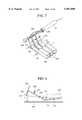
- FIG. 7is a view of an appearance of a receiving antenna driving mechanism of the tablet unit of FIG. 6.
- FIG. 8is a side view of the drive mechanism of FIG. 7.
- FIG. 9is a perspective view of an appearance of a lock tablet unit according to a third embodiment of the present invention.
- FIGS. 10A and 10Bare views of a receiving antenna drive mechanism of the tablet unit of FIG. 9, FIG. 10A being a view of an appearance thereof and FIG. 10B being a view of a side appearance.
- FIG. 11is a perspective view of an appearance of a soccer tablet unit according to a fourth embodiment of the present invention.
- FIG. 12is a view of an appearance of a touch pen drive mechanism of the tablet unit of FIG. 11.
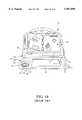
- FIG. 13is a perspective view of an appearance of a shooting game tablet unit according to a fifth embodiment of the present invention.
- FIG. 14is a view of an appearance of a touch pen drive mechanism of the tablet unit of FIG. 13.
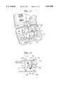
- FIG. 15is a perspective view of an appearance of a register game tablet unit according to a sixth embodiment of the present invention.
- FIGS. 16A to 16Care sectional views of grips of the tablet unit of FIG. 15, which shows a structure thereof.
- FIGS. 17A and 17Bare views of an example of receiving antenna drive mechanism of the tablet unit of FIG. 15.
- FIG. 18is a view of an appearance of a video game device the present invention is applicable to.
- the tablet unit for car games according to a first embodiment of the present inventionwill be explained with reference to FIGS. 1 to 5.
- FIG. 1is a perspective view of the tablet unit mounted on a video game device.
- FIG. 2is a broken structural view of the tablet unit.
- FIG. 3is an explanatory view of an internal structure of the tablet unit.
- the tablet unit for a car 10which is the tablet unit includes a body 36 formed like a dashboard of the car and is to be mounted on a video game device 12, an image device.
- the body 36is formed in the shape of a box which is a set of an upper body 38 of the body and a lower body 40 thereof.
- the upper body 38comprises an operation unit including a handle 42, a direction command lever 44, a shift lever 46, an ignition key 48, etc., and a pen holding unit 50 for holding a touch pen 32 (see FIG. 1).
- the lower body 40comprises a tablet opposed surface 52 which covers the tablet 28 shown in FIG. 18 and is positioned on a bottom lid 16 of a game device body 14, a button opposed surface 54 positioned on a direction button 24 and an execution button 26, and a holder opposed surface 56 positioned on the touch pen holder 30.
- the upper body 38 and the lower body 40are castings of a resin.
- the upper body 38 and the lower body 40are screw-assembled. For the screw-assembling, flat screws 41 with washers are used.
- an interior space defined by the upper body 38 and the lower body 40 assembled togetheraccommodates a sealed cover 58 of metal in the shape of a box having the bottom surface opened.
- the sealed cover 58 accommodated in the interior spacecovers an interior space containing the substantially entire tablet opposed surface 52 and a part of the holder opposed surface 56.
- a plurality of member connection holes 60are opened in the sealed cover 58. Through the member connection holes 60 the members outside and inside the sealed cover 58 are connected to each other (see FIG. 3).
- the handle 42is mounted on a handle mount 62 projected substantially at the center of the upper surface of the upper body 38.
- the handle 42is formed in a ring shape having a rotary base 64 at the center thereof.
- the rotary base 64is rotatably inserted in a base receiver 66 of a handle mount 62.
- the rotary base 64permits the handle 42 to be freely rotated with respect to the handle mount 62.
- a KLAXON (an electrically operated horn or warning signal) 68is mounted on the upper surface of the rotary base 64 has a rod-shaped operative portion 70 and a pair of locking portions 72 formed on the backside of the KLAXON 68.
- the handle 42is locked to the locking portions 72 by coiled spring provided urged on the outside of the operative portion 70 to thereby mount the KLAXON 68 capable of being pressed down with respect to the handle 42.
- the KLAXON 68 mounted on the handle 42has the operative portion 70 passed through the handle mount 62 and projected into the interior space in the sealed cover 58.
- the operative portion 70 projected in the interior spaceabuts upon a KLAXON arm extended along the tablet opposed surface 52 through the receiver 76, a spring 78 for neutralizing the handle and a rotary portion 80 (see FIG. 2).
- the KLAXON arm 82is formed in a strip-shape and has one end 82b thereof journalled to the upper body 38 so that the other end 82a thereof is movable to and from the lower body 40.
- An abutment portion 84 for the forward end of the operative portion to abut uponis provided on the substantially longitudinal middle part of the KLAXON arm 82.
- a rod-shaped projection 86is formed on the backside of one end 82a. The projection 86 is located on an execution button hole 88 in the button opposed surface 54. The execution button hole 88 is provided on the execution button 26 of the game device body 14.
- One end 82a of the KLAXON arm 82is normally pulled up to the inside of the upper body 38 by a tension spring 90 mounted on the upper surface thereof 82a.
- a tension spring 90mounted on the upper surface thereof 82a.
- the execution button 26can be turned on.
- the receiver 76 and the rotary portion 80are respectively formed in the shape of a disc having a through-hole in the center thereof, and are secured by screws respectively to the handle 42 and the receiver 76.
- the rotary portion 80is fixed to the receiver 76, whereby the spring 78 for neutralizing the handle is integrated with the receiver 76 and the rotary portion 80.
- the spring 78 for neutralizing the handleexerts urging force against rotation of the receiver 76 and the rotary portion 80. The urging force returns the handle 42 to its neutral position when no operational force is exerted to the handle 42.
- the rotary portion 80has a locking pawl 92 projected from a peripheral portion thereof sideways and downward.
- the locking pawl 92is engaged in a locking hole 96 in a handle arm 94.
- the handle arm 94is interlocked with the handle 42 through the locking pawl 92.
- the handle arm 94has a substantially T-shape including a transverse plate 98 and a perpendicular plate 100 extended from a part of the transverse plate 98 nearer to one end thereof and is disposed horizontal with respect to the tablet opposed surface 52.
- the transverse plate 98has a slot-shaped locking hole 96 opened widthwise in the substantially central part thereof, and two slot-shaped mounting holes 102 respectively opened lengthwise in both end portions thereof.
- the perpendicular plate 100has a slot-shaped slide hole 104 opened lengthwise.
- the handle arm 94is slidably screw-engaged with the upper body 38 through both mounting holes 102 with the transverse plate 98 positioned substantially parallel with longer sides of the tablet opposed surface 52.
- the rotary portion 80is rotated together with the receiver 76, and the rotation of the rotary portion 90 reciprocates through the locking pawl 92 the handle arm 94 along the longer sides of the tablet opposed surface 52.
- a shift lever arm 106is positioned on the perpendicular plate 100 of the handle arm 94.
- the shift lever arm 106has a substantial cross-shape including a transverse plate 108 and a perpendicular plate 110 with respect to the transverse plate 108, and has a bent portion 112 on one end portion thereof which is bent upward near the intersection.
- a slot-shaped slide hole 114is opened lengthwise in the other end portion of the transverse plate 108.
- the bent portion 112has a recess 116 opened in the upper end thereof.
- the transverse plate 110has two slot-shaped mount holes 118 opened lengthwise in both end portions thereof.
- the shift lever arm 106is slidably secured to the upper body 38 by screws through both mount holes 118 with the perpendicular plate 110 positioned substantially parallel with the shorter sides of the tablet opposed surface 52.
- a locking projection 130 of the shift lever 46which will be explained later is engaged in the recess 116 of the bent portion 112, and shift lever arm 106 is interlocked with the shift lever 46 through the bent portion 112.
- the shift lever 46is mounted on a shift lever mount 120 provided on a side of the upper surface of the upper body 38.
- the shift lever mount 120has an elongate groove extended from the rear to the front of the upper body 38.
- the shift lever 46has a swing member 124 and a knob 128 projected from a cover 126 on the upper end of the swing member 124.
- a locking projection 130is projected from an upper part of the swing member 124 and a swing shaft 132 projected below the locking projection, spaced therefrom.
- the swing shaft 132is swingably received by a bearing 134 formed on the tablet opposed surface 52 of the lower body 40.
- the swing shaft 132is received by the bearing 134 with the locking projection 130 engaged in the recess 116 in the bent portion 112.
- the swing shaft 132is received by the bearing 134, whereby the knob 128 projected through the opening 122 is movable to-and-fro along the opening 122.
- the shift lever 46is operated by holding the knob 128, whereby the swing member 124 is swung on the swing shaft 132, and the swing of the swing member 124 reciprocates the shift lever arm 106 through the locking projection 130 along the shorter sides of the tablet opposed surface 52.
- a receiving antenna 138is mounted through an antenna mount 136 on the backside of the perpendicular plate 100 of the handle arm 138.
- the antenna mount 136includes a spring mount 140 and a receiver 142.
- the spring mount 140includes a disc portion 144 and a shaft 146 projected from the backside of the disc portion 144, and a through-hole 148 is formed in the disc portion 144 and the shaft 146.
- the receiver 142includes a disc portion 150 and cylindrical portion 152 projected from the upper surface of the disc portion 150, and a through-hole communicating with the cylindrical portion 152 is opened in the disc portion 152 (not shown).
- the shaft 145 with a coil spring 154 mounted oncan be inserted into the cylindrical portion 152.
- the receiving antenna 138is formed of a metal plate including an about 35 mm-diameter disc 156 and an about 5 mm-height wall erected around the disc 156.
- Two antenna cables 160a, 160bare attached respectively to the disc 156 and the wall 158. By leading out the two antenna cables 160a, 160b from the disc 156 and the wall 158, the receiving antenna 138 can have an effective receiving area as large as possible.
- the antenna cable 160a attached to the substantial center of the disc 156is passed through the receiver 142 and the spring mount 140, next through the antenna mount 136, further through the slide hole 104 in the handle arm 94 and the slide hole 114 in the shift lever arm 106, and then through a cable receiver 162 positioned on the transverse plate 108 of the shift lever arm 106.
- the antenna mount 136 the antenna cable 160 is passed throughis disposed substantially vertical to the tablet opposed surface 52 so that the antenna cable 160 is invulnerable to influence of electromagnetic waves.
- the antenna mount 136 and the receiving antenna 138are positioned between the handle arm 94 and the tablet opposed surface 52 of the lower body 40.
- the coil spring 154is mounted on the shaft 146 of the spring mount, and the shaft 146 is inserted in the cylindrical portion 152 of the receiver 142.
- the receiving antenna 138 located between the disc portion 150 on the lower end of the cylindrical portion 152 and the tablet opposed surface 52is normally pressed against the tablet opposed surface 52 by urging force of the coil spring 154.
- the receiving antenna 138is slided on the tablet opposed surface 52 through the handle arm 94, and is slided on the tablet opposed surface 52 through the shift lever arm 106 by operation of the shift lever 46.
- the handle arm 94is moved in a range of the slide hole 114 in the shift lever arm 106, and the shift lever arm 106 is moved in a range of the slide hole 104 in the handle arm 94.
- the two antenna cables 160a, 160b led from the receiving antenna 138are connected to a noise reduction circuit 164.
- the noise reduction circuit 164includes an intermediate frequency transducer 166 for 455 kHz.
- the primary side of the intermediate frequency transducer 166constitutes a serial oscillation circuit having an oscillation point at 455 kHz by a coil 168 and a condenser 170, and the secondary side of the intermediate frequency transducer 166 constitutes a parallel oscillation circuit having an oscillation point at 455 kHz by a condenser 172.
- the noise reduction circuit 164is disposed in the body 36.
- a ground plug 182 connected to the sealed cover 58is connected to either of an image output terminal of the game device body 14 and an audio output terminal (not shown) thereof for grounding.
- the plug 182has a jack 184 which is the image output terminal or the audio output terminal of the game device body 14.
- the noise reduction circuit 164, and the sealed cover 58 covering the noise reduction circuit 164, the receiving antenna 138, the antenna 178 on the touch pen and the antenna cables 160a, 160bcan reduce influence of external noises, such as induced noises from human bodies, electromagnetic waves from home electric apparatuses, specifically electronic ranges, personal computers, television picture tubes, etc., electromagnetic waves of radio communication, etc.
- external noisessuch as induced noises from human bodies, electromagnetic waves from home electric apparatuses, specifically electronic ranges, personal computers, television picture tubes, etc., electromagnetic waves of radio communication, etc.
- the tablet opposed surface 52is formed of a resin containing no carbon.
- the antenna on the touch pen 178is formed of metal in a cup-shape which embraces the tip of the touch pen 32 and is mounted on a key arm 186.
- the key arm 186is formed in a strip shape and has the pen receiver 188 on one end.
- the pen receiver 188is positioned in the pen holder unit 50 and accommodates the antenna 178 on the touch pen.
- a pin 190is provided in the substantial lengthwise center of the key arm 186, and the pin is rotatably screw-engaged in the upper body 38.
- a cylindrical key receiver 192is provided adjacent to the key arm 186.
- the key receiver 192is mounted on an ignition key 48 mounted on a key mount 194 formed in the upper body 38.
- the lower end portion of the ignition key 48 mounted on the key mount 194is projected through a hole 196 in the key mount 194 beyond the backside of the upper body 38.
- To the lower end portionis screw-engaged with the key receiver 192.
- the key receiver 192 screw-engaged with the ignition key 48is rotated circumferentially in accordance with rotation of the ignition key 48.
- the other end 186a of the key arm 186is in contact with the outer circumferential surface of the key receiver 192.
- On a part of the outer circumference of the key receiver 192there is formed an operational convexity 195 on which the other end 186a of the key arm 186 goes up when the key receiver 192 is rotated.
- the key arm 186is swung on the pin 190.
- the pen receiver 188accommodating the antenna 178 on the touch pen with the tip inserted in is moved in direction of pressing down the tip of the touch pen.
- a direction command lever 44is mounted on the base receiver 66 of the handle mount 62.
- the direction command lever 44includes a ring-shaped lever base 196, and an operational portion 198 projected over the outer circumference of the lever base 196.
- the lever base 196is mounted on the outside of a base receiver 66 rotatable with respect to the base receiver 66.
- a secular recess 200is formed beside the base receiver 66.
- a lever connector 202is mounted on the underside of the lever base 196 of the direction command lever 44 from the recess 200 into the interior space.
- the lever connector 202includes a click in the shape of an arc which conforms to a shape of the recess 200, and a connection rod 206 projected from the lower end of the click 204.
- the clickis secured by a screw to the lever base 196.
- the lever connector 202is moved in the recess 200 together with the direction command lever 44, which is swung on the base receiver 66.
- a movement range of the lever connector 202 moved in the recess 200is a swing range of the direction command lever 44.
- Three vertical grooves 208are formed in the outer circumferential surface of the click 204.
- a ball receiver 212 having a click ball 210is provided outside the click 204.
- the click ball 210is urged by a coil spring 214 to be licked with the grooves 208.
- the direction command lever 44can be displaced forward and to the foreground as viewed in the drawing from a position substantially alongside of the handle mount 62 while the click ball 210 is locked in the associated grooves, giving click feeling.
- the forward end of the connection rod of the lever connector 202is engaged in a locking hole 218 in a direction command lever arm 216 disposed along the tablet opposed surface 52 and the button opposed surface 54.
- the direction command lever arm 216is formed in a strip-shape and has the locking hole 218 in one end portion and a widened portion 220 on the other end portion.
- the locking hole 218is a lengthwise slot, and the widened portion 220 is formed in the shape of a ring having an opening 222.
- the direction command lever arm 216has the substantially central part thereof mounted on the upper body 38 by a screw capable of being swung on the screw. Thus, the direction command lever arm 216 is interlocked with the direction command lever 44 through the forward end of the connection rod 206 locked in the locking hole 218 and the lever connector 202.
- buttons 24a, 24b, 24c, 24d of the game device body 14there are provided an upper button receiver 224a, a lower button receiver 224b, a left button receiver 224c and a right button receiver 224d.
- the button receivers 224a, 224b, 224c, 224dare arranged in a cross corresponding to the direction buttons 24a, 24b, 24c, 24d of the game device body 14.
- the button receivers 224a, 224b, 224c, 224dare formed in cylinders having the bottoms opened on the buttons 24a, 24b, 24c, 24d of the game device body 14.
- Respective direction command buttons 226are mounted on the upper open ends of the upper button receiver 224a and the lower button receiver 224b.
- the direction command button 226includes a disc-shaped head 228 exposed through the upper open end, a rod 236 inserted at the upper open end and projected beyond the bottom surface of the head 228.
- Operational portions 232are mounted on the lower open ends of the upper button receiver 224a and the lower button receiver 224b. Each operational portion includes a disc-shaped head 234 exposed through the lower open end, a rod 236 inserted at the lower open end and projected beyond the bottom surface of the head 234.
- the rod 230 of the direction command button 226 and the rod 230 of the operational portion 232abut on each other, and with the head 234 of the direction command button 226 abutting on the upper open end, the head 234 of the operational portion 232 is pushed downward of the lower open end.
- the head 234 of the operational portion 232is pushed out to thereby press down the upward direction button 24a of the game device body 14 or the downward direction button 24b thereof.
- An upper wall 237a and a lower wall 237bare erected, spaced from each other on the underside of the forward portion of the widened portion 220 of the direction command lever arm 216.
- the upper wall 237ais positioned in a trace which is over the direction command button 226 mounted on the upper button receiver 224a
- the lower wall 237bis positioned in a trace which is over the direction command button 226 mounted on the lower button receiver 224b.
- the upper wall 237a and the lower wall 237bhave a positional relationship that when the upper wall 237a goes on the direction command button 226, the lower wall 237b does not go on the direction command button 226, and the upper wall 237a does not go on the direction command button 226 when the lower wall 237b goes on the direction command button 226.
- the upper wall 237a and the lower wall 237bdo not go on the direction command button 226.
- the upper wall 237agoes on the direction command button 226 of the upper button receiver 224a, presses down the operational portion 232 and presses down the upper direction button 24a of the game device body 14.
- the lower wall 237bgoes on the direction command button 226 of the lower button receiver 224b, presses down the operational portion 232 and presses down the downward button 24b of the game device body 14.
- Respective selection buttons 238are mounted on the upper open ends of the right button receiver 224c and the left button receiver 224d.
- Each selection button 238includes a disc-shaped head 240 exposed through the upper open end, a rod 242 inserted at the upper open end and projected beyond the bottom surface of the head 240.
- the head 240has a two-stage structure having a smaller-diameter upper end portion 240a. The forward end of the rod 242 is exposed through the lower open end.
- a coil spring 244is mounted around the rod 242 between the head 240 and the upper open end. The coil spring 244 exerts to the selection button 238 urging force which is against downward press force.
- the selection button mount 246includes two receivers 248 which are in the form of openings having a size which can accommodate the upper end portions 240a of the heads 240 of the selection buttons 238 are formed in the selection button mount 246.
- the selection buttons 238abuts on the section button mount 246 at the underside of the upper body 38 with the upper end portions 240a exposed through the receivers 248.
- the forward end of the rod 242presses down the left direction button 24c.
- the forward end of the rod 242presses down the right direction button 24d of the game device body 14.
- the left button receiver 224cis outside a displacement range of the widened portion 220, and the right button receiver 224d is positioned in the opening 222 in the widened portion 220, whereby the operation of the direction command lever 44 and that of the selection button 238 do not interfere with each other.
- fixation members 250for fixing the car tablet unit 10 mounted on the tablet 28 to the game device body 14.
- Each fixation member 250includes a rectangular clamping plate 252, and two pairs of rod mounts 254 disposed on an upper part of the inside of the clamping plate 252.
- the lower ends of the clamping plates 252reach the side surfaces of the bottom lid 16.
- a rod 258is mounted on each pair of rod mounts for retaining a spring 256 thereon. Both ends of each rod 258 are jutted outside of the rod mounts 254 of each pair. Both ends of each rod 258 are clamped between a pair of upper rod receivers 260 of the upper body 38 and a pair of lower rod receivers 262 on the lower body 40.
- the upper rod receivers 260 of each pairare spaced from each other so that the rod mounts 254 of each pair are positioned between the rod receivers 260 of each pair, and are projected from both side surfaces of the upper body 38.
- Each upper rod receiver 260has a groove for receiving the rod formed in the underside thereof.
- the lower rod receivers 262 of each pairare spaced from each other so that the rod mounts 254 of each pair are positioned between the rod receivers 260 of each pair, and are projected from both side surfaces of the lower body 40.
- Each lower rod receiver 260has a groove for receiving the rod formed in the underside thereof.
- the springs 256are so mounted that when the upper body 38 and the lower body 40 are assembled together, the lower ends of the clamping plates 252 are urged to the body 36.
- the urging force of the springs 256enables both clamping plates 252 to clamp the video game device body 14 on both sides thereof.
- the car tablet unit 10is mounted on the video game device body 14, the touch pen 32 is accommodated in the pen holder member 50, and the pen tip 32a is inserted in the antenna 178 on the touch pen, and the following operation is enabled.
- the handle 42 or the shift lever 46is operated to change a moving direction or a speed of a displayed car.
- the receiving antenna 138When the handle 42 or the shift lever 46 is operated, the receiving antenna 138 is moved over the tablet opposed surface 52. The receiving antenna 138 is pressed against the tablet opposed surface 52 in contact with the tablet 28 and receives electromagnetic waves from the tablet 28 to transmit the same to the pen tip 32a.
- the electromagnetic waves generated by the tablet 28contain vertical Y-axis components and horizontal X-axis components, and the receiving antenna 138 receives Y-axis components and X-axis components which indicate positional coordinates of moving positions.
- the receiving antenna 138When the handle 42 is turned right, the receiving antenna 138 is moved right over the tablet opposed surface 52 and receives electromagnetic waves of positional coordinates of the receiving antenna 138 and transmits the same to the pen tip 32a. In accordance with positional coordinates transmitted to the pen tip 32a, a car, a display image, is moved right.
- the receiving antenna 138When the handle 42 is turned left, the receiving antenna 138 is moved left over the tablet opposed surface 52 and receives electromagnetic waves of positional coordinates of the receiving antenna 138 and transmit the same to the pen tip 32a.
- the car, a display imageIn accordance with positional coordinates transmitted to the pen tip 32a, the car, a display image, is moved left.
- the handle 42When the handle 42 is neutral, the car, a display image, is directed forward without changing a direction.
- the receiving antenna 138When the shift lever 46 is operated, the receiving antenna 138 is moved vertically.
- the antenna 178 on the touch penis moved, and pushes in the pen tip 23a of the touch pen 32 or releases the pushed-in pen tip 32a.
- the pen switchis turned on/off to change display images and do other function.
- the direction command lever 44one of the upward direction button 24a of the video game device body 14 or the downward direction button 24b thereof can be pressed.
- the KLAXON 68the execution button 26 can be pressed.
- the selection button 238, the left direction button 24c or the right direction button 24dcan be pressed.
- the car tablet unit 10is mounted on the video game device body 14.
- the touch pen 32is accommodated in the pen holder member 50.
- An initial display of the drive gameis displayed on the display screen.
- the ignition key 48is operated to start the engine.
- the carstarts, and the display is changed. As shown in FIG. 5, a car A driving along a road is displayed on the display screen.
- the handle 42is operated to change a direction of the car A.
- the handle 42is turned left or right, and the car A changes the direction to the left or the right to which the handle 42 has been turned.
- the car Aapproaches to the shoulder of the road and enter the building of the gas station G.
- the direction command lever 44 in place of the handle 42is operated to change the direction of the car A.
- a direction indicator D interlocked with the car Aflashes.
- the KLAXON 68can be operated to sound.
- the speed of the car Acan be controlled among three stages of stop, low speed and high speed. During the stop, idling sound is made, at the low speed, low-speed driving sound is made, and at the high speed, high-speed driving sound is made.
- a monitor displayis changed to a display of an inside of the gas station G, and events of oiling and car washing, etc., can be selected.
- Eventscan be selected and executed by operating the selection button 238, can be selected by the direction command lever 44 and executed by the selection button 238, or are selected by the handle 42 and executed by the selection button 238. Not only events, but also games, etc. can be selected and executed by the selection button 238.
- the gamecan be played by operating the handle 42, the direction command lever 44, the shift lever 46, the ignition key 48, the KLAXON 68 and the selection button 238 of the car tablet unit 10.
- Contents of the game cartridge in the video game device 12can be directly selected by dismounting the touch pen 32 from the pen holder member 50, dismounting the antenna 178 of the touch pen and operating the touch pen 32.
- the tablet unitincludes the body in the shape of a car dashboard, and the receiving antenna 138 on the tablet 28 is operated, whereby game players can feel as if they were actually driving a car, the so-called virtual reality feeling. This makes the game itself exciting.
- the tabletis in the form of the car dashboard but may be in the form of a vehicle other than a car, e.g., a bike, airplane, spaceship, submarine, boat or others.
- keyboard tabletwhich is the tablet unit according to a second embodiment of the present invention will be explained with reference to FIGS. 6 to 8.
- FIG. 6is a perspective view of the keyboard tablet mounted on a video game device.
- the keyboard tablet 300is mounted on a tablet 28 of the video game device 12.
- the tablet unit 300includes a body 302 imitating a keyboard.
- the body 302is formed in the shape of a box which is an assembly of an upper lid 304 and a back lid 306. Eight keys 308 are arranged widthwise on the upper lid 304, and a touch pen mount hole 310 is formed therein.
- the back lid 306covers the tablet 28.
- the keysare accommodated in the body 302 except the upper surfaces and rear end surfaces of the keys.
- syllables 312do, re, mi, fa, sol, la, ti, do representing the tones of the diatonic scale are written.
- swing platesare attached to rear parts of the backsides of the keys 308 housed in the body 302.
- a swing pin 316is provided on forward parts of the backsides of the keys 308.
- Rear ends of operational plates 318are mounted on forward end portions of the swing plates 314.
- An operational plate pin 320is provided on the upper surfaces of rear end portions of the operational plates 318.
- cylindrical antenna shafts 322are mounted inclined.
- Disc-shaped receiving antennas 324are mounted on the downward ends of the respective cylindrical antenna shafts 322.
- the antenna shafts 322 and the receiving antennas 324are substantially perpendicular to each other.
- One ends of antenna cables 326are connected to the substantial centers of the receiving antennas 324.
- the antenna cables 326are wired through the antenna shafts 322 and has the other ends connected to an antenna 328 on the touch pen.
- Coil springs 330are attached to the upper surfaces of the operational plates 318 for pulling upward the operational plates 318. To receive without erroneous operations electromagnetic waves radiated from the surface of the tablet it is preferable that the operational plates 318 are retained by the coil springs 330 when the keys 308 are not pressed so that the receiving antennas 324 are spaced by about 20 mm from the back lid 306.
- the antenna 328 on the touch penis formed of a metal in the shape of a cup which embraces the tip of the touch pen 32 as in the first embodiment, and is disposed in a touch pen mount hole (FIG. 6).
- the eight antenna cables 326 from the receiving antennas 324 mounted on the respective keys 308are connected to the antenna 328 on the touch pen.
- the tip of the touch pen 32can be inserted in the antenna 328 on the touch pen by inserting the touch pen 32 into the touch pen mount hole 310 with the tip thereof ahead.
- the tablet unit 300is mounted on the tablet 28 of the video game device 12, and the touch pen 32 is disposed in the touch pen mount hole 310.
- the back lid 306 of the mounted tablet unit 300covers the tablet 28, and the tip of the touch pen 32 is inserted into the antenna on the touch pen.
- an arbitrary one of the keys 308is pressed down.
- the forward end of the swing plate 314 associated with the pressed-down key 308is swung upward on the key pin 316.
- the tip of the swing plate 314is swung upward, the lower end of the operational plate associated with the swing plate 314 is pushed upward, and the operational plate 318 is swung on the operational plate pin 320 as the swing fulcrum against urging force of the coil spring 330.
- the swing of the operational plate 318presses the receiving antenna 324 associated with the operational plate 318 against the back lid 306.
- the receiving antenna 324 pressed against the back lid 306receives electromagnetic waves from the tablet 28 and transmits the same to the pen tip 32a.
- the electromagnetic waves from the tablet 28contain vertical Y-axis component and horizontal X-axis component, and the receiving antenna 324 received X-axis component and a Y-axis component indicating coordinates of a place on the back lid 306 against which the operational plate 318 is pressed.
- the key 308When the key 308 is released from the press-down, the key 308 is returned to its original position by the urging force of the coil spring 330.
- a mechanism shown in FIG. 8may be used in pressing down a key 308 to press the associated receiving antenna 324 against the back lid 306.
- the key swing pin 31is disposed on the undersides of the forward end of the keys 308, and the rear ends of the swing plates 314 abut on the undersides of the rear ends (on the foreground) of the keys 308.
- the swing pin 332is disposed on the underside of the substantially longitudinal center of the swing plates 314, and the rear ends of the operational plates 318 are mounted on the forward ends of the swing plates 314.
- the operational plate pin 320is disposed on the upper surface of a rear end part of the operational plates 318.
- the receiving antennas 324are mounted on the forward ends of the operational plates 318 through the antenna shafts 322.
- the operation of the mechanism of FIG. 8is the same as that of the mechanism of FIG. 7.
- a key 308is pressed down, the rear end of the key is swung down on the key pin 316 as the swing fulcrum, and the associated swing plate 314 is swung on the swing plate pin 332 as the swing fulcrum.
- the swing plate 314is swung with the forward end swung upward, the lower end of the associated operational plate 318 is pressed downward, whereby the associated receiving antenna 324 is pressed against the back lid 306.
- Information transmission from the receiving antenna 324 to the touch pen 32, and the operation upon releasing the key 308are the same as in the mechanism of FIG. 7.
- the tablet unit 300gives the video game device 12 the function of a keyboard, and a plurality of receiving antennas 324 on the tablet 28 are operated by the keys 308, whereby players (children) can easily experience playing musical instruments, which is very effective from the viewpoint of emotional education.
- FIG. 9is a perspective view of the tablet unit mounted on a video game device, which shows its state. As shown in FIG. 9, the tablet unit 400 is mounted on a tablet of the video game device 12.
- the tablet unit 400includes a body 402 imitating a clock.
- the body 402is formed in the shape of a box formed by assembling an upper lid 404 and a back lid 406 (FIG. 10).
- a dial 408 and a touch pen mount 410are disposed on the upper lid 404.
- the back lid 406covers the tablet 28 (FIG. 18). Needles (long, short and second needles) 412 which can be rotated to an arbitrary position by a player are disposed on the dial 408.
- the needles 412for example, is secured to an end portion of a short needle shaft 414 passed through the dial 408, and the short needle shaft 414 is rotatably mounted on the back lid 406 rotatably by a bearing 416.
- the short needle shaft 414further includes a circular metal plate 418 integrated therewith on the dial 408.
- a support arm 420is extended radially outward from the metal plate 418 at a position opposed to the short needle 412.
- the antenna support arm 420secures on the forward end a cylinder 422 opened toward the back lid 406.
- the cylinder 422is inserted into a tappet-shaped receiving antenna 424 through a compression spring 426.
- the coil spring 426urges the receiving antenna 424 against the back lid 406, so that the receiving antenna 424 can efficiently receive electromagnetic waves from the tablet 28.
- One end of an antenna cable 425is connected substantially to the center of the receiving antenna 424.
- the antenna cable 425is wired through the shaft of the receiving antenna, and the other end of the cable 425 is connected to the metal plate 418.
- the antenna on the touch penis formed in the shape of a cup of metal as in the above-described embodiments, and is disposed in a touch pen mount hole 410 (FIG. 9).
- a strip-shaped antenna cable 430which friction-contacts a rotary metal plate 418 to supply to the antenna 428 on the touch pen information transmitted from the receiving antenna 424 to the metal plate 418 through the cable.
- the touch pen 32has the tip inserted in the antenna 428 on the touch pen by inserting the touch pen into the touch pen mount hole 410 with the tip ahead.
- the tablet unit 400is mounted on the tablet 28 of the video device 12, and the touch pen 32 is disposed in the touch pen mount hole 410.
- the back lid 406 of the mounted tablet unit 400covers the tablet 28, and the tip of the touch pen 32 is inserted into the antenna 428 on the touch pen.
- a playerrotates the needle 412 to a required position in accordance with a command of the image monitor.
- the metal plate 418is rotated on the bearing 416, and in accordance with this, the receiving antenna 424 is rotated to the required position on the back lid 406.
- the receiving antenna 424 pressed against the back lid 406 at the required positionreceives electromagnetic waves from the tablet 28 and transmits positional information of the position to the tip 32a of the touch pen 32 through the antenna cable 425, the metal plate 418 and the antenna cable 430.
- the electromagnetic waves generated by the tablet 28contain vertical Y-axis component and horizontal x-axis component, and the receiving antenna 424 receives x-axis components and y-axis components indicative of positional coordinates of the position on the back lid 406 to which the receiving antenna is contacted.
- the video game device 12Based on the positional coordinates transmitted to the pen tip 32a, the video game device 12 compares needle position information inputted by, e.g., the touch pen 32 with a time commanded to the monitor, and in accordance with a comparison result, correct or incorrect, a prescribed image or chimes are outputted.
- the tablet unit 400gives the video game device 12 a function of a toy clock, and the receiving antenna 42 on the tablet 28 is operated by the needle 412, whereby players (children) can physically learn the mechanism and characteristics of the clock.
- the present embodimentcan achieve sufficient advantageous effect in terms of emotional education.
- the mechanismis described by using the short needle, but it is possible that the receiving antenna 424 can be driven in a more sophisticated manner by using the long and the short needles.
- the tablet for a soccer game according to the fourth embodiment of the present inventionwill be explained with reference to FIGS. 11 and 12.
- the touch pen 32is inserted in the touch pen mount hole, and positional information received by the receiving antenna is transmitted to the touch pen 32 through the cable.
- the touch pen 32itself is made movable by securing the touch pen to a movable formed object, and electromagnetic waves from the tablet surface are directly received by the touch pen.
- a dollwhich is an operation unit, and a touch pen are interlocked so that the touch pen 32 is directly moved by operating the doll.
- the tablet unit 500is mounted on the tablet of the video game device 12.
- the tablet unit 500includes a body 502 imitating a soccer field.
- the body 502is formed in the shape of a box formed by assembling an upper lid 504 and a back lid 506.
- a soccer playere.g., a goal keeper
- a touch pen mount opening 510is formed in a side of the body 502.
- the back lid 506covers the tablet 28 (FIG. 18).
- the goal keeper 508 and the touch pen 32normally intersects each other, and are interlocked with each other by a horizontal lever 512 which is longitudinally movable, a vertical lever 514 and a gear assembly 516.
- a pen socket 518is secured to one end of the horizontal lever 512.
- the pen socket 518is capable of contacting a tip 32a of the touch pen 32 inserted in the body through the touch pen mount opening 510.
- the horizontal lever 512is housed longitudinally displaceable in a lever cover 520 a partial section of which is shown in the drawing.
- a cylindrical antenna shaft 520ais suspended from the underside of the lever cover 520 downward to the back lid 506.
- a pen holder 520b for holding the forward end of the inserted touch pen 32is provided on the end of the lever cover 520.
- a receiving antenna 522is vertically movably inserted in the antenna shaft 520a through a spring 521.
- An antenna cable 524 extended from the pen socket 518is connected to the substantial center of the receiving antenna 522.
- the antenna cable 524is wired through the lever cover 520.
- the tablet unit 500is mounted on the tablet 28 of the video game device 12, and the touch pen 32 is securely inserted in the pen holder 520b.
- the back lid 506 of the tablet unit 500covers the tablet 28.
- a game playerpresses down the head 508a of the goal keeper 508 toward the tablet 28 (in the direction of the arrow).
- a core member 526 integrated with the head 508arotates pinion gears 516a, 516b, whereby the legs 508b of the goal keeper interlocked with the pinion gear 516b is rotated in a manner like licking a ball.
- the rotation of the pinion gear 516amoves the vertical lever 514 in the direction of the arrow, and the movement displaces through the gear 516c the horizontal lever 512 in the direction of the arrow.
- the pen socket 518 on the forward end of the leveris brought into contact with the pen tip 22a, and positional information of a position of the receiving antenna 522 is transmitted to the touch pen 32.
- the game playerpresses down the head 508a of the goal keeper 508 to move the goal keeper horizontally and vertically on the tablet, whereby the game player blocks shoots displayed on the monitor or kicks the ball to the opponent's goal.
- the tablet unit 500gives the video game device 12 a function of a soccer game device, and a game player directly operates a soccer player 508 to directly operate the receiving antenna 522, whereby the game can be more realistic.
- the receiving antenna 522 and the touch pen 32are displaced in accordance with movements of the soccer player 508, which enables a game player to play the game intuitive operations without using complicated directional button 24 and execution button 26, which can improve response in the game.
- FIGS. 13 and 14a shooting tablet unit which is the tablet unit according to a fifth embodiment of the present invention will be explained with reference to FIGS. 13 and 14.
- FIG. 13is a perspective view of the shooting tablet unit mounted on a video game device.
- the tablet unit 600is mounted on a tablet 28 of the video game device 12.
- the tablet unit 600includes a body 60 with a gun 602 mounted on.
- the bodyis formed in the shape of a box formed by assembling an upper lid 606 and a back lid 608.
- the gun 602is mounted on the upper lid swingably left and right. Near the forward end of the gun 602, a touch pen mount 610 for receiving a touch pen from above is disposed.
- the back lid 608covers the tablet 28.
- the gun 602includes grips 612 disposed on the side opposed to a game player.
- a trigger button 614 called a triggeris withdrawably provided in one of the grips 612.
- a gun seat 616 for the gun 602 mounted onis projected upward with respect to the upper lid 606.
- the lower support arm 618includes a shaft 618a inserted in the boss 620 through a spring 619 and is mounted on the boss by suitable means vertically movably and preventively of fall by suitable means.
- the touch pen 32has the portion on the side of the cord integrally supported by an upper support arm 622 which is integral with the trigger button 614, and the upper support arm 622 is urged upward by a spring 624 seated in the gun body.
- the touch pen 32is always in contact with the inside surface of the back lid 608.
- the tablet unit 600is mounted on the tablet 28 of the video game device 12, and the touch pen 32 is inserted in the touch pen mount 610 is secured to the upper support arm 622.
- a game playerrotates the gun 602 on the gun seat 616 by using the grips 612 with respect to an object displayed on an image monitor (in the directions of double arrow in the drawing). Because the touch pen 32 is always in contact with the back lid 608, the object can be followed based on positional information of the touch pen 32.
- the trigger button 614downward force of the trigger button 614 is transmitted to the touch pen 32 through the upper support arm 622, then the touch pen is lowered with respect to the gun 602, and the switch on the pen tip is pressed. Then a bullet is fired to shoot down an enemy plane.
- a game playermoves the gun 602 left and right, and presses the trigger button 614, whereby enemy planes displayed on the image monitor are shot down, or attack vehicles, such as war vehicles, armored cars, etc., and the game player competes in points counted by, e.g., numbers of shoot-downs.
- the tablet unit 600gives the video game device 12 a function of a shooting game device, and a player directly operates a toy gun to aim at an object and shoot it. This makes the game more realistic.
- the touch pen 32is displaced in accordance with motions of the gun 602, which makes it possible to omit the receiving antenna to the advantage of lower costs.
- FIG. 15is a perspective view of the register tablet unit 700 mounted on a video game device 12. As shown in FIG. 15, the register tablet unit 700 covers a tablet 28 of the video game device (FIG. 18), and includes a body 702 imitating a register.
- the bodyis formed by assembling an upper lid 704 and a back lid 706. On the upper lid 704, register button unit 708 and a grip set unit 710 are disposed as in a register.
- the back lid 706covers the tablet 28.
- the register tablet unit 700includes a bar code reader-type grip 712 on which a touch pen 32 can be mounted.
- FIG. 16shows sectional views of examples of the grips which are usable on the present embodiment.
- the grip 712mainly includes a substantially T-shaped grip casing 714, a receiver socket 716 which is positioned on the forward end of the grip 717 and is withdrawable with respect to the grip casing 714, and a spring 718 urging the receiver socket 716 to the front of the grip.
- the receiver socket 716is, e.g., a one-piece molding, and has a recess 716a for receiving the pen tip 32a of the touch pen formed in the side thereof near the grip casing 714.
- the grip 712is for pressing a specific pattern on picture software 22 (FIG. 18) mounted on the video game device 12. The grip 12 is pressed into the picture software 22 and the receiver socket 716 is pushed toward the touch pen by its reaction force, and the switch of the touch pen 32 is turned on.
- a distance between the transmitting surface (the side of the picture software) and the receiver side (the pen tip 32a)is made as short as possible so that receiving efficiency of the grip 712 pressing down the picture book software surface to receive is not lowered.
- the tablet unit 700can receive, in addition to information from the picture book software, information from the register button unit 708 operated by a game player.
- FIG. 16Bshows a grip which can receive positional information from the tablet side in addition to the above-described receiving efficiency improvement.
- a metal member 720 for inputting positional information (electromagnetic waves) from the tablet 28is buried in the center of the receiving socket 16.
- register buttonsare pressed to transmit electromagnetic waves from the register buttons to the grip set unit 710, and a transmission metal member 722 disposed here and the metal member 720 contact each other to thereby button information is transmitted to the touch pen 32 (FIG. 16C).
- FIGS. 17A and 17Bshow a second embodiment showing relationships between the register button unit 708 and the transmission metal part 722 disposed on the grip set unit 701.
- FIG. 17Ashows an example including key-shaped register buttons 724 similar to those of the second embodiment
- FIG. 17Bshows an example including vertical movable usual buttons 726.
- Receiving antenna 728 associated with the respective buttonsare provided, and the receiving antennas 728 are pressed against the back lid to receive electromagnetic waves from the tablet and transmits the electromagnetic waves to the metal member 722 through a cable 730.
- the tablet unit 700gives the video game device 12 a function of the bar code register, and a game player holds and operates the grip 712 to receive optionally from the picture book software or from the tablet surface, whereby shopping games can have more functions, which makes the games more amusing.
- the present inventionis not limited to the above-described embodiments and covers various modifications.
- the present inventionis usable as tablets for portable electric computers, slip-in puzzle games, multi-musical instruments, such as drums, etc. in addition to the above-described keyboard, handles of motor bikes, etc.
Landscapes
- Engineering & Computer Science (AREA)
- Multimedia (AREA)
- Human Computer Interaction (AREA)
- Input From Keyboards Or The Like (AREA)
- Position Input By Displaying (AREA)
- Toys (AREA)
Abstract
Description
Claims (13)
Applications Claiming Priority (2)
| Application Number | Priority Date | Filing Date | Title |
|---|---|---|---|
| JP07567196AJP3709447B2 (en) | 1996-03-29 | 1996-03-29 | Tablet unit |
| JP8-075671 | 1996-03-29 |
Publications (1)
| Publication Number | Publication Date |
|---|---|
| US5967898Atrue US5967898A (en) | 1999-10-19 |
Family
ID=13582906
Family Applications (1)
| Application Number | Title | Priority Date | Filing Date |
|---|---|---|---|
| US08/825,059Expired - Fee RelatedUS5967898A (en) | 1996-03-29 | 1997-03-27 | Tablet unit |
Country Status (3)
| Country | Link |
|---|---|
| US (1) | US5967898A (en) |
| JP (1) | JP3709447B2 (en) |
| KR (1) | KR970064658A (en) |
Cited By (70)
| Publication number | Priority date | Publication date | Assignee | Title |
|---|---|---|---|---|
| KR970064658A (en)* | 1996-03-29 | 1997-10-13 | 이리마지리 쇼우이찌로 | Tablet unit |
| US6209845B1 (en) | 1998-02-04 | 2001-04-03 | Klitsner Industrial Design, Llc | Keyboard interface |
| US6244960B1 (en)* | 1997-03-06 | 2001-06-12 | Sega Enterprises, Ltd. | Tablet unit and virtual experience method |
| US6296571B1 (en)* | 1999-03-02 | 2001-10-02 | Logitech Europe S.A. | Steering wheel spring assembly |
| US20010044334A1 (en)* | 2000-05-19 | 2001-11-22 | Konami Corporation | Readable storage medium storing action game program, and action game device and control method for same |
| US6322449B1 (en)* | 1998-02-04 | 2001-11-27 | Klitsner Industrial Design, Llc | Mechanical interface device |
| US6364771B1 (en)* | 2000-02-10 | 2002-04-02 | Mattel, Inc. | Handheld electronic game apparatus having attacking feature |
| US6401033B1 (en)* | 2000-09-01 | 2002-06-04 | Navigation Technologies Corp. | Navigation system with game playing feature |
| US6435875B1 (en)* | 2001-02-12 | 2002-08-20 | Mattel, Inc. | Electronic bulldozer game |
| US6461238B1 (en)* | 2000-08-03 | 2002-10-08 | Rehco, Llc | Portable simulation game apparatus |
| US20030016210A1 (en)* | 2001-06-18 | 2003-01-23 | Leapfrog Enterprises, Inc. | Three dimensional interactive system |
| US20030087699A1 (en)* | 2001-11-02 | 2003-05-08 | Brumagin James G | Toy driving simulator and method of using the same |
| US6811491B1 (en)* | 1999-10-08 | 2004-11-02 | Gary Levenberg | Interactive video game controller adapter |
| US20050048459A1 (en)* | 2003-08-29 | 2005-03-03 | Gubitosi Domenic T. | Educational toy with actuators and correlated audible and visual output |
| US6876354B1 (en)* | 1999-07-09 | 2005-04-05 | Link Evolution Co., Ltd. | Keyboard type input device and portable information processor |
| US20050255916A1 (en)* | 2004-05-12 | 2005-11-17 | Paul Chen | Adaptable game controller |
| USD532461S1 (en) | 2005-11-10 | 2006-11-21 | Mattel, Inc. | Electronic toy house |
| USD533773S1 (en) | 2005-09-26 | 2006-12-19 | Mattel, Inc. | Packaging for a toy |
| USD535707S1 (en) | 2005-08-25 | 2007-01-23 | Mattel, Inc. | Electronic toy house |
| US20070018393A1 (en)* | 2005-07-07 | 2007-01-25 | Mattel, Inc. | Methods of playing drawing games and electronic game systems adapted to interactively provide the same |
| USD536042S1 (en) | 2005-11-10 | 2007-01-30 | Mattel, Inc. | Electronic toy house |
| US20070076362A1 (en)* | 2005-09-30 | 2007-04-05 | Isaac Lagnado | Computer device having multi-function handle |
| US20080015017A1 (en)* | 2006-05-09 | 2008-01-17 | Nintendo Co., Ltd. | Game controller |
| US20080070197A1 (en)* | 2006-09-20 | 2008-03-20 | Mattel, Inc. | Interactive toy vehicle cockpit |
| US20090191532A1 (en)* | 2008-01-24 | 2009-07-30 | Mark Sanderson | Scale model collectible dash replica device |
| US20090203294A1 (en)* | 2008-02-09 | 2009-08-13 | Jessica Kessin | Motor skills development toy device |
| US7596466B2 (en) | 2006-03-28 | 2009-09-29 | Nintendo Co., Ltd. | Inclination calculation apparatus and inclination calculation program, and game apparatus and game program |
| USD602096S1 (en) | 2007-07-05 | 2009-10-13 | Nintendo Co., Ltd. | Attachment for controller |
| US7774155B2 (en) | 2006-03-10 | 2010-08-10 | Nintendo Co., Ltd. | Accelerometer-based controller |
| US7874918B2 (en) | 2005-11-04 | 2011-01-25 | Mattel Inc. | Game unit with motion and orientation sensing controller |
| US7927216B2 (en) | 2005-09-15 | 2011-04-19 | Nintendo Co., Ltd. | Video game system with wireless modular handheld controller |
| US7931535B2 (en) | 2005-08-22 | 2011-04-26 | Nintendo Co., Ltd. | Game operating device |
| USD637653S1 (en)* | 2010-07-01 | 2011-05-10 | Thq Inc. | Game tablet |
| US7942745B2 (en) | 2005-08-22 | 2011-05-17 | Nintendo Co., Ltd. | Game operating device |
| US8089458B2 (en) | 2000-02-22 | 2012-01-03 | Creative Kingdoms, Llc | Toy devices and methods for providing an interactive play experience |
| US8157651B2 (en) | 2005-09-12 | 2012-04-17 | Nintendo Co., Ltd. | Information processing program |
| US8226493B2 (en) | 2002-08-01 | 2012-07-24 | Creative Kingdoms, Llc | Interactive play devices for water play attractions |
| US8267786B2 (en) | 2005-08-24 | 2012-09-18 | Nintendo Co., Ltd. | Game controller and game system |
| US8308563B2 (en) | 2005-08-30 | 2012-11-13 | Nintendo Co., Ltd. | Game system and storage medium having game program stored thereon |
| US8313379B2 (en) | 2005-08-22 | 2012-11-20 | Nintendo Co., Ltd. | Video game system with wireless modular handheld controller |
| US8475275B2 (en) | 2000-02-22 | 2013-07-02 | Creative Kingdoms, Llc | Interactive toys and games connecting physical and virtual play environments |
| US8568213B2 (en) | 2005-11-04 | 2013-10-29 | Mattel, Inc. | Game unit with controller-determined characters |
| US8574050B2 (en) | 2005-11-04 | 2013-11-05 | Mattel, Inc. | Game unit with dual joystick controllers |
| US8608535B2 (en) | 2002-04-05 | 2013-12-17 | Mq Gaming, Llc | Systems and methods for providing an interactive game |
| US8702515B2 (en) | 2002-04-05 | 2014-04-22 | Mq Gaming, Llc | Multi-platform gaming system using RFID-tagged toys |
| US8708821B2 (en) | 2000-02-22 | 2014-04-29 | Creative Kingdoms, Llc | Systems and methods for providing interactive game play |
| US8753165B2 (en) | 2000-10-20 | 2014-06-17 | Mq Gaming, Llc | Wireless toy systems and methods for interactive entertainment |
| US8758136B2 (en) | 1999-02-26 | 2014-06-24 | Mq Gaming, Llc | Multi-platform gaming systems and methods |
| US8812987B2 (en) | 2011-12-20 | 2014-08-19 | Wikipad, Inc. | Virtual multiple sided virtual rotatable user interface icon queue |
| US8944912B2 (en) | 2011-12-20 | 2015-02-03 | Wikipad, Inc. | Combination game controller and information input device for a tablet computer |
| USD723551S1 (en)* | 2013-08-01 | 2015-03-03 | Conny Technology Co., Ltd. | Tablet computer for children |
| US9005026B2 (en) | 2011-12-20 | 2015-04-14 | Wikipad, Inc. | Game controller for tablet computer |
| USD730993S1 (en) | 2013-09-20 | 2015-06-02 | Wms Gaming Inc. | Inclined input interface for a gaming terminal |
| US9114319B2 (en) | 2012-06-12 | 2015-08-25 | Wikipad, Inc. | Game controller |
| US9126119B2 (en) | 2012-06-12 | 2015-09-08 | Wikipad, Inc. | Combination computing device and game controller with flexible bridge section |
| US9349240B2 (en) | 2013-09-20 | 2016-05-24 | Bally Gaming, Inc. | Gaming terminal with an inclined input interface |
| US9407100B2 (en) | 2011-12-20 | 2016-08-02 | Wikipad, Inc. | Mobile device controller |
| US9446319B2 (en) | 2003-03-25 | 2016-09-20 | Mq Gaming, Llc | Interactive gaming toy |
| WO2016178256A1 (en)* | 2015-05-05 | 2016-11-10 | Xplored S.R.L. | Control device for video games with controls without physical contact |
| US9592452B2 (en) | 2011-12-20 | 2017-03-14 | Wikipad, Inc. | Combination computing device and game controller with flexible bridge section |
| US9592453B2 (en) | 2011-12-20 | 2017-03-14 | Wikipad, Inc. | Combination computing device and game controller with flexible bridge section |
| USD795963S1 (en) | 2017-01-11 | 2017-08-29 | Nintendo Co., Ltd. | Accessory of controller for computer |
| US9757649B2 (en) | 2011-12-20 | 2017-09-12 | Wikipad, Inc. | Game controller with flexible bridge supporting touch screen |
| US9764231B2 (en) | 2011-12-20 | 2017-09-19 | Wikipad, Inc. | Combination computing device and game controller with touch screen input |
| US9841824B2 (en) | 2011-12-20 | 2017-12-12 | Wikipad, Inc. | Combination computing device and game controller with flexible bridge and supporting a keyboard module |
| US9839842B2 (en) | 2011-12-20 | 2017-12-12 | Wikipad, Inc. | Computing device and game controller with flexible bridge supporting a keyboard module |
| US9841786B2 (en) | 2011-12-20 | 2017-12-12 | Wikipad, Inc. | Combination computing device and game controller with flexible bridge and supporting a transaction apparatus |
| US9895606B1 (en) | 2017-01-11 | 2018-02-20 | Nintendo Co., Ltd. | Accessory device |
| US10016067B2 (en) | 2015-09-09 | 2018-07-10 | Kids Ii, Inc. | Convertible children's walker |
| US10092830B2 (en) | 2011-12-20 | 2018-10-09 | Wikipad, Inc. | Game controller with flexible bridge supporting point of sale input device |
Citations (9)
| Publication number | Priority date | Publication date | Assignee | Title |
|---|---|---|---|---|
| US33662A (en)* | 1861-11-05 | Improvement in | ||
| US4353552A (en)* | 1979-02-23 | 1982-10-12 | Peptek, Incorporated | Touch panel system and method |
| US4716804A (en)* | 1982-09-23 | 1988-01-05 | Joel Chadabe | Interactive music performance system |
| US4899137A (en)* | 1987-09-26 | 1990-02-06 | Aeg Olympia Aktiengesellschaft | Arrangement for the input and processing of characters and/or graphic patterns |
| US4945357A (en)* | 1988-08-29 | 1990-07-31 | Rotal Industries & Trading Ltd. | Joystick assembly |
| USRE33662E (en) | 1983-08-25 | 1991-08-13 | TV animation interactively controlled by the viewer | |
| JPH05137846A (en)* | 1991-11-21 | 1993-06-01 | Sega Enterp Ltd | Electronic book reading method and device |
| US5269522A (en)* | 1991-09-20 | 1993-12-14 | Graphic Technology, Inc. | Apparatus and method for promotional contests |
| US5681220A (en)* | 1994-03-18 | 1997-10-28 | International Business Machines Corporation | Keyboard touchpad combination in a bivalve enclosure |
Family Cites Families (5)
| Publication number | Priority date | Publication date | Assignee | Title |
|---|---|---|---|---|
| JP2784811B2 (en)* | 1989-08-25 | 1998-08-06 | ソニー株式会社 | Image creation device |
| JP2953267B2 (en)* | 1992-10-13 | 1999-09-27 | コナミ株式会社 | External memory control device in image creation device |
| JP3563428B2 (en)* | 1993-11-30 | 2004-09-08 | ヤマハ株式会社 | Multimedia control device |
| JP3709447B2 (en)* | 1996-03-29 | 2005-10-26 | 株式会社セガ | Tablet unit |
| JPH10328413A (en)* | 1997-05-30 | 1998-12-15 | Wacom Co Ltd | Operating equipment for video game |
- 1996
- 1996-03-29JPJP07567196Apatent/JP3709447B2/ennot_activeExpired - Fee Related
- 1997
- 1997-03-27USUS08/825,059patent/US5967898A/ennot_activeExpired - Fee Related
- 1997-03-28KRKR1019970011220Apatent/KR970064658A/ennot_activeCeased
Patent Citations (9)
| Publication number | Priority date | Publication date | Assignee | Title |
|---|---|---|---|---|
| US33662A (en)* | 1861-11-05 | Improvement in | ||
| US4353552A (en)* | 1979-02-23 | 1982-10-12 | Peptek, Incorporated | Touch panel system and method |
| US4716804A (en)* | 1982-09-23 | 1988-01-05 | Joel Chadabe | Interactive music performance system |
| USRE33662E (en) | 1983-08-25 | 1991-08-13 | TV animation interactively controlled by the viewer | |
| US4899137A (en)* | 1987-09-26 | 1990-02-06 | Aeg Olympia Aktiengesellschaft | Arrangement for the input and processing of characters and/or graphic patterns |
| US4945357A (en)* | 1988-08-29 | 1990-07-31 | Rotal Industries & Trading Ltd. | Joystick assembly |
| US5269522A (en)* | 1991-09-20 | 1993-12-14 | Graphic Technology, Inc. | Apparatus and method for promotional contests |
| JPH05137846A (en)* | 1991-11-21 | 1993-06-01 | Sega Enterp Ltd | Electronic book reading method and device |
| US5681220A (en)* | 1994-03-18 | 1997-10-28 | International Business Machines Corporation | Keyboard touchpad combination in a bivalve enclosure |
Cited By (166)
| Publication number | Priority date | Publication date | Assignee | Title |
|---|---|---|---|---|
| KR970064658A (en)* | 1996-03-29 | 1997-10-13 | 이리마지리 쇼우이찌로 | Tablet unit |
| US6244960B1 (en)* | 1997-03-06 | 2001-06-12 | Sega Enterprises, Ltd. | Tablet unit and virtual experience method |
| US6209845B1 (en) | 1998-02-04 | 2001-04-03 | Klitsner Industrial Design, Llc | Keyboard interface |
| US6322449B1 (en)* | 1998-02-04 | 2001-11-27 | Klitsner Industrial Design, Llc | Mechanical interface device |
| US8888576B2 (en) | 1999-02-26 | 2014-11-18 | Mq Gaming, Llc | Multi-media interactive play system |
| US8758136B2 (en) | 1999-02-26 | 2014-06-24 | Mq Gaming, Llc | Multi-platform gaming systems and methods |
| US9186585B2 (en) | 1999-02-26 | 2015-11-17 | Mq Gaming, Llc | Multi-platform gaming systems and methods |
| US9861887B1 (en) | 1999-02-26 | 2018-01-09 | Mq Gaming, Llc | Multi-platform gaming systems and methods |
| US9468854B2 (en) | 1999-02-26 | 2016-10-18 | Mq Gaming, Llc | Multi-platform gaming systems and methods |
| US10300374B2 (en) | 1999-02-26 | 2019-05-28 | Mq Gaming, Llc | Multi-platform gaming systems and methods |
| US9731194B2 (en) | 1999-02-26 | 2017-08-15 | Mq Gaming, Llc | Multi-platform gaming systems and methods |
| US6296571B1 (en)* | 1999-03-02 | 2001-10-02 | Logitech Europe S.A. | Steering wheel spring assembly |
| US6876354B1 (en)* | 1999-07-09 | 2005-04-05 | Link Evolution Co., Ltd. | Keyboard type input device and portable information processor |
| US6811491B1 (en)* | 1999-10-08 | 2004-11-02 | Gary Levenberg | Interactive video game controller adapter |
| US6364771B1 (en)* | 2000-02-10 | 2002-04-02 | Mattel, Inc. | Handheld electronic game apparatus having attacking feature |
| US8790180B2 (en) | 2000-02-22 | 2014-07-29 | Creative Kingdoms, Llc | Interactive game and associated wireless toy |
| US8531050B2 (en) | 2000-02-22 | 2013-09-10 | Creative Kingdoms, Llc | Wirelessly powered gaming device |
| US8368648B2 (en) | 2000-02-22 | 2013-02-05 | Creative Kingdoms, Llc | Portable interactive toy with radio frequency tracking device |
| US8475275B2 (en) | 2000-02-22 | 2013-07-02 | Creative Kingdoms, Llc | Interactive toys and games connecting physical and virtual play environments |
| US9814973B2 (en) | 2000-02-22 | 2017-11-14 | Mq Gaming, Llc | Interactive entertainment system |
| US9149717B2 (en) | 2000-02-22 | 2015-10-06 | Mq Gaming, Llc | Dual-range wireless interactive entertainment device |
| US8814688B2 (en) | 2000-02-22 | 2014-08-26 | Creative Kingdoms, Llc | Customizable toy for playing a wireless interactive game having both physical and virtual elements |
| US10188953B2 (en) | 2000-02-22 | 2019-01-29 | Mq Gaming, Llc | Dual-range wireless interactive entertainment device |
| US8491389B2 (en) | 2000-02-22 | 2013-07-23 | Creative Kingdoms, Llc. | Motion-sensitive input device and interactive gaming system |
| US8089458B2 (en) | 2000-02-22 | 2012-01-03 | Creative Kingdoms, Llc | Toy devices and methods for providing an interactive play experience |
| US9713766B2 (en) | 2000-02-22 | 2017-07-25 | Mq Gaming, Llc | Dual-range wireless interactive entertainment device |
| US8686579B2 (en) | 2000-02-22 | 2014-04-01 | Creative Kingdoms, Llc | Dual-range wireless controller |
| US10307671B2 (en) | 2000-02-22 | 2019-06-04 | Mq Gaming, Llc | Interactive entertainment system |
| US9579568B2 (en) | 2000-02-22 | 2017-02-28 | Mq Gaming, Llc | Dual-range wireless interactive entertainment device |
| US8184097B1 (en) | 2000-02-22 | 2012-05-22 | Creative Kingdoms, Llc | Interactive gaming system and method using motion-sensitive input device |
| US8169406B2 (en) | 2000-02-22 | 2012-05-01 | Creative Kingdoms, Llc | Motion-sensitive wand controller for a game |
| US9474962B2 (en) | 2000-02-22 | 2016-10-25 | Mq Gaming, Llc | Interactive entertainment system |
| US8708821B2 (en) | 2000-02-22 | 2014-04-29 | Creative Kingdoms, Llc | Systems and methods for providing interactive game play |
| US8164567B1 (en) | 2000-02-22 | 2012-04-24 | Creative Kingdoms, Llc | Motion-sensitive game controller with optional display screen |
| US8915785B2 (en) | 2000-02-22 | 2014-12-23 | Creative Kingdoms, Llc | Interactive entertainment system |
| US20010044334A1 (en)* | 2000-05-19 | 2001-11-22 | Konami Corporation | Readable storage medium storing action game program, and action game device and control method for same |
| US7063616B2 (en)* | 2000-05-19 | 2006-06-20 | Konami Corporation | Readable storage medium storing action game program, and action game device and control method for same |
| US6461238B1 (en)* | 2000-08-03 | 2002-10-08 | Rehco, Llc | Portable simulation game apparatus |
| US6401033B1 (en)* | 2000-09-01 | 2002-06-04 | Navigation Technologies Corp. | Navigation system with game playing feature |
| US9931578B2 (en) | 2000-10-20 | 2018-04-03 | Mq Gaming, Llc | Toy incorporating RFID tag |
| US8753165B2 (en) | 2000-10-20 | 2014-06-17 | Mq Gaming, Llc | Wireless toy systems and methods for interactive entertainment |
| US8961260B2 (en) | 2000-10-20 | 2015-02-24 | Mq Gaming, Llc | Toy incorporating RFID tracking device |
| US10307683B2 (en) | 2000-10-20 | 2019-06-04 | Mq Gaming, Llc | Toy incorporating RFID tag |
| US9320976B2 (en) | 2000-10-20 | 2016-04-26 | Mq Gaming, Llc | Wireless toy systems and methods for interactive entertainment |
| US9480929B2 (en) | 2000-10-20 | 2016-11-01 | Mq Gaming, Llc | Toy incorporating RFID tag |
| US6435875B1 (en)* | 2001-02-12 | 2002-08-20 | Mattel, Inc. | Electronic bulldozer game |
| WO2002065431A1 (en)* | 2001-02-12 | 2002-08-22 | Mattel, Inc. | Electronic bulldozer game |
| US9393491B2 (en) | 2001-02-22 | 2016-07-19 | Mq Gaming, Llc | Wireless entertainment device, system, and method |
| US9162148B2 (en) | 2001-02-22 | 2015-10-20 | Mq Gaming, Llc | Wireless entertainment device, system, and method |
| US8913011B2 (en) | 2001-02-22 | 2014-12-16 | Creative Kingdoms, Llc | Wireless entertainment device, system, and method |
| US8248367B1 (en) | 2001-02-22 | 2012-08-21 | Creative Kingdoms, Llc | Wireless gaming system combining both physical and virtual play elements |
| US9737797B2 (en) | 2001-02-22 | 2017-08-22 | Mq Gaming, Llc | Wireless entertainment device, system, and method |
| US10179283B2 (en) | 2001-02-22 | 2019-01-15 | Mq Gaming, Llc | Wireless entertainment device, system, and method |
| US8711094B2 (en) | 2001-02-22 | 2014-04-29 | Creative Kingdoms, Llc | Portable gaming device and gaming system combining both physical and virtual play elements |
| US8384668B2 (en) | 2001-02-22 | 2013-02-26 | Creative Kingdoms, Llc | Portable gaming device and gaming system combining both physical and virtual play elements |
| US10758818B2 (en) | 2001-02-22 | 2020-09-01 | Mq Gaming, Llc | Wireless entertainment device, system, and method |
| US20030016210A1 (en)* | 2001-06-18 | 2003-01-23 | Leapfrog Enterprises, Inc. | Three dimensional interactive system |
| WO2002103382A3 (en)* | 2001-06-18 | 2003-02-27 | Leapfrog Entpr Inc | Three dimensional interactive system |
| US6954199B2 (en) | 2001-06-18 | 2005-10-11 | Leapfrog Enterprises, Inc. | Three dimensional interactive system |
| US20030087699A1 (en)* | 2001-11-02 | 2003-05-08 | Brumagin James G | Toy driving simulator and method of using the same |
| US6805604B2 (en) | 2001-11-02 | 2004-10-19 | Mattel, Inc. | Toy driving simulator |
| US10507387B2 (en) | 2002-04-05 | 2019-12-17 | Mq Gaming, Llc | System and method for playing an interactive game |
| US11278796B2 (en) | 2002-04-05 | 2022-03-22 | Mq Gaming, Llc | Methods and systems for providing personalized interactive entertainment |
| US8608535B2 (en) | 2002-04-05 | 2013-12-17 | Mq Gaming, Llc | Systems and methods for providing an interactive game |
| US9272206B2 (en) | 2002-04-05 | 2016-03-01 | Mq Gaming, Llc | System and method for playing an interactive game |
| US8702515B2 (en) | 2002-04-05 | 2014-04-22 | Mq Gaming, Llc | Multi-platform gaming system using RFID-tagged toys |
| US10478719B2 (en) | 2002-04-05 | 2019-11-19 | Mq Gaming, Llc | Methods and systems for providing personalized interactive entertainment |
| US10010790B2 (en) | 2002-04-05 | 2018-07-03 | Mq Gaming, Llc | System and method for playing an interactive game |
| US9463380B2 (en) | 2002-04-05 | 2016-10-11 | Mq Gaming, Llc | System and method for playing an interactive game |
| US9616334B2 (en) | 2002-04-05 | 2017-04-11 | Mq Gaming, Llc | Multi-platform gaming system using RFID-tagged toys |
| US8827810B2 (en) | 2002-04-05 | 2014-09-09 | Mq Gaming, Llc | Methods for providing interactive entertainment |
| US8226493B2 (en) | 2002-08-01 | 2012-07-24 | Creative Kingdoms, Llc | Interactive play devices for water play attractions |
| US10022624B2 (en) | 2003-03-25 | 2018-07-17 | Mq Gaming, Llc | Wireless interactive game having both physical and virtual elements |
| US11052309B2 (en) | 2003-03-25 | 2021-07-06 | Mq Gaming, Llc | Wireless interactive game having both physical and virtual elements |
| US9770652B2 (en) | 2003-03-25 | 2017-09-26 | Mq Gaming, Llc | Wireless interactive game having both physical and virtual elements |
| US9039533B2 (en) | 2003-03-25 | 2015-05-26 | Creative Kingdoms, Llc | Wireless interactive game having both physical and virtual elements |
| US8373659B2 (en) | 2003-03-25 | 2013-02-12 | Creative Kingdoms, Llc | Wirelessly-powered toy for gaming |
| US9993724B2 (en) | 2003-03-25 | 2018-06-12 | Mq Gaming, Llc | Interactive gaming toy |
| US10583357B2 (en) | 2003-03-25 | 2020-03-10 | Mq Gaming, Llc | Interactive gaming toy |
| US9707478B2 (en) | 2003-03-25 | 2017-07-18 | Mq Gaming, Llc | Motion-sensitive controller and associated gaming applications |
| US9446319B2 (en) | 2003-03-25 | 2016-09-20 | Mq Gaming, Llc | Interactive gaming toy |
| US8961312B2 (en) | 2003-03-25 | 2015-02-24 | Creative Kingdoms, Llc | Motion-sensitive controller and associated gaming applications |
| US10369463B2 (en) | 2003-03-25 | 2019-08-06 | Mq Gaming, Llc | Wireless interactive game having both physical and virtual elements |
| US9393500B2 (en) | 2003-03-25 | 2016-07-19 | Mq Gaming, Llc | Wireless interactive game having both physical and virtual elements |
| US20050048459A1 (en)* | 2003-08-29 | 2005-03-03 | Gubitosi Domenic T. | Educational toy with actuators and correlated audible and visual output |
| US20050255916A1 (en)* | 2004-05-12 | 2005-11-17 | Paul Chen | Adaptable game controller |
| US9675878B2 (en) | 2004-09-29 | 2017-06-13 | Mq Gaming, Llc | System and method for playing a virtual game by sensing physical movements |
| US20110201396A1 (en)* | 2005-07-07 | 2011-08-18 | Janice Ritter | Methods of playing drawing games and electronic game systems adapted to interactively provide the same |
| US7887058B2 (en) | 2005-07-07 | 2011-02-15 | Mattel, Inc. | Methods of playing drawing games and electronic game systems adapted to interactively provide the same |
| US20070018393A1 (en)* | 2005-07-07 | 2007-01-25 | Mattel, Inc. | Methods of playing drawing games and electronic game systems adapted to interactively provide the same |
| US9011248B2 (en) | 2005-08-22 | 2015-04-21 | Nintendo Co., Ltd. | Game operating device |
| US10155170B2 (en) | 2005-08-22 | 2018-12-18 | Nintendo Co., Ltd. | Game operating device with holding portion detachably holding an electronic device |
| US9700806B2 (en) | 2005-08-22 | 2017-07-11 | Nintendo Co., Ltd. | Game operating device |
| US7931535B2 (en) | 2005-08-22 | 2011-04-26 | Nintendo Co., Ltd. | Game operating device |
| US7942745B2 (en) | 2005-08-22 | 2011-05-17 | Nintendo Co., Ltd. | Game operating device |
| US9498728B2 (en) | 2005-08-22 | 2016-11-22 | Nintendo Co., Ltd. | Game operating device |
| US10238978B2 (en) | 2005-08-22 | 2019-03-26 | Nintendo Co., Ltd. | Game operating device |
| US8313379B2 (en) | 2005-08-22 | 2012-11-20 | Nintendo Co., Ltd. | Video game system with wireless modular handheld controller |
| US10661183B2 (en) | 2005-08-22 | 2020-05-26 | Nintendo Co., Ltd. | Game operating device |
| US9044671B2 (en) | 2005-08-24 | 2015-06-02 | Nintendo Co., Ltd. | Game controller and game system |
| US9498709B2 (en) | 2005-08-24 | 2016-11-22 | Nintendo Co., Ltd. | Game controller and game system |
| US11027190B2 (en) | 2005-08-24 | 2021-06-08 | Nintendo Co., Ltd. | Game controller and game system |
| US10137365B2 (en) | 2005-08-24 | 2018-11-27 | Nintendo Co., Ltd. | Game controller and game system |
| US8834271B2 (en) | 2005-08-24 | 2014-09-16 | Nintendo Co., Ltd. | Game controller and game system |
| US9227138B2 (en) | 2005-08-24 | 2016-01-05 | Nintendo Co., Ltd. | Game controller and game system |
| US8267786B2 (en) | 2005-08-24 | 2012-09-18 | Nintendo Co., Ltd. | Game controller and game system |
| USD535707S1 (en) | 2005-08-25 | 2007-01-23 | Mattel, Inc. | Electronic toy house |
| US8308563B2 (en) | 2005-08-30 | 2012-11-13 | Nintendo Co., Ltd. | Game system and storage medium having game program stored thereon |
| US8157651B2 (en) | 2005-09-12 | 2012-04-17 | Nintendo Co., Ltd. | Information processing program |
| US8708824B2 (en) | 2005-09-12 | 2014-04-29 | Nintendo Co., Ltd. | Information processing program |
| USRE45905E1 (en) | 2005-09-15 | 2016-03-01 | Nintendo Co., Ltd. | Video game system with wireless modular handheld controller |
| US7927216B2 (en) | 2005-09-15 | 2011-04-19 | Nintendo Co., Ltd. | Video game system with wireless modular handheld controller |
| US8430753B2 (en) | 2005-09-15 | 2013-04-30 | Nintendo Co., Ltd. | Video game system with wireless modular handheld controller |
| USD533773S1 (en) | 2005-09-26 | 2006-12-19 | Mattel, Inc. | Packaging for a toy |
| US20070076362A1 (en)* | 2005-09-30 | 2007-04-05 | Isaac Lagnado | Computer device having multi-function handle |
| US8574050B2 (en) | 2005-11-04 | 2013-11-05 | Mattel, Inc. | Game unit with dual joystick controllers |
| US8568213B2 (en) | 2005-11-04 | 2013-10-29 | Mattel, Inc. | Game unit with controller-determined characters |
| US7874918B2 (en) | 2005-11-04 | 2011-01-25 | Mattel Inc. | Game unit with motion and orientation sensing controller |
| USD532461S1 (en) | 2005-11-10 | 2006-11-21 | Mattel, Inc. | Electronic toy house |
| USD536042S1 (en) | 2005-11-10 | 2007-01-30 | Mattel, Inc. | Electronic toy house |
| US7774155B2 (en) | 2006-03-10 | 2010-08-10 | Nintendo Co., Ltd. | Accelerometer-based controller |
| US7596466B2 (en) | 2006-03-28 | 2009-09-29 | Nintendo Co., Ltd. | Inclination calculation apparatus and inclination calculation program, and game apparatus and game program |
| US8591333B2 (en) | 2006-05-09 | 2013-11-26 | Nintendo Co. Ltd. | Game controller with receptor duplicating control functions |
| US20110195785A1 (en)* | 2006-05-09 | 2011-08-11 | Nintendo Co., Ltd. | Game controller |
| US8550915B2 (en) | 2006-05-09 | 2013-10-08 | Nintendo Co., Ltd. | Game controller with adapter duplicating control functions |
| US20080015017A1 (en)* | 2006-05-09 | 2008-01-17 | Nintendo Co., Ltd. | Game controller |
| US20080070197A1 (en)* | 2006-09-20 | 2008-03-20 | Mattel, Inc. | Interactive toy vehicle cockpit |
| USD602096S1 (en) | 2007-07-05 | 2009-10-13 | Nintendo Co., Ltd. | Attachment for controller |
| US20090191532A1 (en)* | 2008-01-24 | 2009-07-30 | Mark Sanderson | Scale model collectible dash replica device |
| US20090203294A1 (en)* | 2008-02-09 | 2009-08-13 | Jessica Kessin | Motor skills development toy device |
| USD637653S1 (en)* | 2010-07-01 | 2011-05-10 | Thq Inc. | Game tablet |
| US9005026B2 (en) | 2011-12-20 | 2015-04-14 | Wikipad, Inc. | Game controller for tablet computer |
| US9841824B2 (en) | 2011-12-20 | 2017-12-12 | Wikipad, Inc. | Combination computing device and game controller with flexible bridge and supporting a keyboard module |
| US8812987B2 (en) | 2011-12-20 | 2014-08-19 | Wikipad, Inc. | Virtual multiple sided virtual rotatable user interface icon queue |
| US9855498B2 (en) | 2011-12-20 | 2018-01-02 | Wikipad, Inc. | Game controller with structural bridge |
| US9841786B2 (en) | 2011-12-20 | 2017-12-12 | Wikipad, Inc. | Combination computing device and game controller with flexible bridge and supporting a transaction apparatus |
| US8944912B2 (en) | 2011-12-20 | 2015-02-03 | Wikipad, Inc. | Combination game controller and information input device for a tablet computer |
| US9839842B2 (en) | 2011-12-20 | 2017-12-12 | Wikipad, Inc. | Computing device and game controller with flexible bridge supporting a keyboard module |
| US10092830B2 (en) | 2011-12-20 | 2018-10-09 | Wikipad, Inc. | Game controller with flexible bridge supporting point of sale input device |
| US9592453B2 (en) | 2011-12-20 | 2017-03-14 | Wikipad, Inc. | Combination computing device and game controller with flexible bridge section |
| US9592452B2 (en) | 2011-12-20 | 2017-03-14 | Wikipad, Inc. | Combination computing device and game controller with flexible bridge section |
| US9808713B1 (en) | 2011-12-20 | 2017-11-07 | Wikipad, Inc. | Game controller with structural bridge |
| US10159895B2 (en) | 2011-12-20 | 2018-12-25 | Wikipad, Inc. | Game controller with structural bridge |
| US9407100B2 (en) | 2011-12-20 | 2016-08-02 | Wikipad, Inc. | Mobile device controller |
| US9764231B2 (en) | 2011-12-20 | 2017-09-19 | Wikipad, Inc. | Combination computing device and game controller with touch screen input |
| US9757649B2 (en) | 2011-12-20 | 2017-09-12 | Wikipad, Inc. | Game controller with flexible bridge supporting touch screen |
| US10391393B2 (en) | 2011-12-20 | 2019-08-27 | Wikipad, Inc. | Game controller with structural bridge |
| US9126119B2 (en) | 2012-06-12 | 2015-09-08 | Wikipad, Inc. | Combination computing device and game controller with flexible bridge section |
| US9114319B2 (en) | 2012-06-12 | 2015-08-25 | Wikipad, Inc. | Game controller |
| USD723551S1 (en)* | 2013-08-01 | 2015-03-03 | Conny Technology Co., Ltd. | Tablet computer for children |
| US10290175B2 (en) | 2013-09-20 | 2019-05-14 | Bally Gaming, Inc. | Gaming terminal with an inclined input interface |
| US9858747B2 (en) | 2013-09-20 | 2018-01-02 | Bally Gaming, Inc. | Gaming terminal with an inclined input interface |
| USD760846S1 (en) | 2013-09-20 | 2016-07-05 | Bally Gaming, Inc. | Inclined input interface for a gaming terminal |
| US9349240B2 (en) | 2013-09-20 | 2016-05-24 | Bally Gaming, Inc. | Gaming terminal with an inclined input interface |
| US10163294B2 (en) | 2013-09-20 | 2018-12-25 | Bally Gaming, Inc. | Gaming terminal with an inclined input interface |
| USD730993S1 (en) | 2013-09-20 | 2015-06-02 | Wms Gaming Inc. | Inclined input interface for a gaming terminal |
| WO2016178256A1 (en)* | 2015-05-05 | 2016-11-10 | Xplored S.R.L. | Control device for video games with controls without physical contact |
| US10130191B2 (en) | 2015-09-09 | 2018-11-20 | Kids Ii, Inc. | Convertible children's walker |
| US10016067B2 (en) | 2015-09-09 | 2018-07-10 | Kids Ii, Inc. | Convertible children's walker |
| US10499749B2 (en) | 2015-09-09 | 2019-12-10 | Kids2, Inc. | Convertible children's walker |
| US10220309B2 (en) | 2017-01-11 | 2019-03-05 | Nintendo Co., Ltd. | Accessory device |
| US10881952B2 (en) | 2017-01-11 | 2021-01-05 | Nintendo Co., Ltd. | Accessory device |
| USD795963S1 (en) | 2017-01-11 | 2017-08-29 | Nintendo Co., Ltd. | Accessory of controller for computer |
| US9895606B1 (en) | 2017-01-11 | 2018-02-20 | Nintendo Co., Ltd. | Accessory device |
| US11771980B2 (en) | 2017-01-11 | 2023-10-03 | Nintendo Co., Ltd. | Accessory device |
| US12134030B2 (en) | 2017-01-11 | 2024-11-05 | Nintendo Co., Ltd. | Accessory device |
Also Published As
| Publication number | Publication date |
|---|---|
| JP3709447B2 (en) | 2005-10-26 |
| KR970064658A (en) | 1997-10-13 |
| JPH09265344A (en) | 1997-10-07 |
Similar Documents
| Publication | Publication Date | Title |
|---|---|---|
| US5967898A (en) | Tablet unit | |
| US8550915B2 (en) | Game controller with adapter duplicating control functions | |
| US7034712B2 (en) | Integrated remote control unit for operating a television and a video game unit | |
| US9573056B2 (en) | Expandable control device via hardware attachment | |
| US8313379B2 (en) | Video game system with wireless modular handheld controller | |
| US6139434A (en) | Three-dimensional image processing apparatus with enhanced automatic and user point of view control | |
| US7488254B2 (en) | Controller and expansion unit for controller | |
| EP2058035B1 (en) | Operation tool, operation input evaluation method, storage medium, and game device | |
| US8184100B2 (en) | Inertia sensing input controller and receiver and interactive system using thereof | |
| US6283857B1 (en) | Three-dimensional image processing apparatus with enhanced automatic and user point of view control | |
| WO1995013850A1 (en) | Virtual bullet loading device for gun game machine | |
| KR20010021809A (en) | Gun-shaped controller and game machine | |
| EP1057504A2 (en) | Vibration generating device and input device for game apparatus using the same | |
| WO2010012211A1 (en) | Gun-type multifunctional input controller for game | |
| CN103337111A (en) | Control device for communicating visual information | |
| US20100149740A1 (en) | Shape-changeable gaming controller | |
| US20050255916A1 (en) | Adaptable game controller | |
| JP4203115B1 (en) | GAME CONTROLLER CASE, PROGRAM, INFORMATION STORAGE MEDIUM, AND GAME DEVICE | |
| JP2008206638A (en) | Wearing tool | |
| JP3532898B2 (en) | Video game toys | |
| US6435875B1 (en) | Electronic bulldozer game | |
| JP2011136049A (en) | Game program | |
| JP5532374B2 (en) | Game control program | |
| JP2009247885A (en) | Game controller case, program, information storage medium, and game apparatus | |
| US20110034224A1 (en) | Operating device of a game console controller |
Legal Events
| Date | Code | Title | Description |
|---|---|---|---|
| AS | Assignment | Owner name:SEGA ENTERPRISES, LTD., JAPAN Free format text:ASSIGNMENT OF ASSIGNORS INTEREST;ASSIGNORS:TAKASAKA, AKIRA;OGAWA, IWAKICHI;REEL/FRAME:008754/0704;SIGNING DATES FROM 19970711 TO 19970716 | |
| FEPP | Fee payment procedure | Free format text:PAYOR NUMBER ASSIGNED (ORIGINAL EVENT CODE: ASPN); ENTITY STATUS OF PATENT OWNER: LARGE ENTITY | |
| AS | Assignment | Owner name:SEGA ENTERPRISES, LTD., JAPAN Free format text:CORRECTIVE ASSIGNMENT TO ADD AN ADDITIONAL ASSINGEE TO THE DOCUMENT PREVIOUSLY RECORDED ON REEL 008754, FRAME 0704;ASSIGNORS:TAKASAKA, AKIRA;OGAWA, IWAKICHI;REEL/FRAME:013001/0767;SIGNING DATES FROM 19970711 TO 19970716 Owner name:SEGA TECH, LTD., JAPAN Free format text:CORRECTIVE ASSIGNMENT TO ADD AN ADDITIONAL ASSINGEE TO THE DOCUMENT PREVIOUSLY RECORDED ON REEL 008754, FRAME 0704;ASSIGNORS:TAKASAKA, AKIRA;OGAWA, IWAKICHI;REEL/FRAME:013001/0767;SIGNING DATES FROM 19970711 TO 19970716 | |
| AS | Assignment | Owner name:SEGA CORPORATION, JAPAN Free format text:CHANGE OF NAME;ASSIGNOR:SEGA ENTERPRISES, LTD.;REEL/FRAME:013323/0318 Effective date:20001201 Owner name:SEGA TOYS LTD., JAPAN Free format text:CHANGE OF NAME;ASSIGNOR:SEGA TECH LTD.;REEL/FRAME:013323/0305 Effective date:19980403 | |
| FEPP | Fee payment procedure | Free format text:PAYOR NUMBER ASSIGNED (ORIGINAL EVENT CODE: ASPN); ENTITY STATUS OF PATENT OWNER: LARGE ENTITY Free format text:PAYER NUMBER DE-ASSIGNED (ORIGINAL EVENT CODE: RMPN); ENTITY STATUS OF PATENT OWNER: LARGE ENTITY | |
| FPAY | Fee payment | Year of fee payment:4 | |
| FPAY | Fee payment | Year of fee payment:8 | |
| REMI | Maintenance fee reminder mailed | ||
| LAPS | Lapse for failure to pay maintenance fees | ||
| STCH | Information on status: patent discontinuation | Free format text:PATENT EXPIRED DUE TO NONPAYMENT OF MAINTENANCE FEES UNDER 37 CFR 1.362 | |
| FP | Lapsed due to failure to pay maintenance fee | Effective date:20111019 |