US5967588A - Visor control - Google Patents
Visor controlDownload PDFInfo
- Publication number
- US5967588A US5967588AUS09/099,972US9997298AUS5967588AUS 5967588 AUS5967588 AUS 5967588AUS 9997298 AUS9997298 AUS 9997298AUS 5967588 AUS5967588 AUS 5967588A
- Authority
- US
- United States
- Prior art keywords
- visor
- torque control
- cylindrical member
- pivot rod
- collar
- Prior art date
- Legal status (The legal status is an assumption and is not a legal conclusion. Google has not performed a legal analysis and makes no representation as to the accuracy of the status listed.)
- Expired - Fee Related
Links
Images


Classifications
- B—PERFORMING OPERATIONS; TRANSPORTING
- B60—VEHICLES IN GENERAL
- B60J—WINDOWS, WINDSCREENS, NON-FIXED ROOFS, DOORS, OR SIMILAR DEVICES FOR VEHICLES; REMOVABLE EXTERNAL PROTECTIVE COVERINGS SPECIALLY ADAPTED FOR VEHICLES
- B60J3/00—Antiglare equipment associated with windows or windscreens; Sun visors for vehicles
- B60J3/02—Antiglare equipment associated with windows or windscreens; Sun visors for vehicles adjustable in position
- B60J3/0204—Sun visors
- B60J3/0213—Sun visors characterised by the mounting means
- B60J3/0265—Attachments of sun visors to mounting means including details of sun visor bearing member regulating the rotational friction on the support arm
Definitions
- the present inventionrelates to a visor torque control.
- visor torque controlswhich are designed to allow a visor to pivot from a stored position adjacent a vehicle headliner to selected lowered use positions.
- the design of such torque controlsrequire that the visor be relatively easily lowered to selected use positions and yet maintain their adjusted position during movement of the vehicle.
- Some torque controls for visorsalso provide detent positions for locking the visor in a raised stored position and/or a primary lowered use position.
- An example of one such torque control which has been in widespread commercial useis represented by U.S. Pat. No. 4,500,131.
- Visorsfrequently include a variety of accessories, such as illuminated vanity mirrors, and in recent years, trainable garage door opening transmitters, cellular telephones and the like.
- accessories integrated into visor bodiesadd to the weight of the visor making the torque control more difficult to design and successfully hold a visor in a desired adjusted position and yet allow ease of use.
- the torque control of the present inventionsolves the need for a torque control which is capable of satisfying the design criteria of modem vehicle visors. It accomplishes this goal by providing a visor torque control made of spring steel formed to circumscribe at least a substantial proportion of a visor pivot rod.
- the pivot rodhas a layer of hardened material forming an external surface of the pivot rod to improve the wear and abrasion resistance of the pivot rod.
- the visor bodywhich is fixedly attached to the torque control, can rotate about the pivot rod with relative ease and yet be held in a secure, adjusted position.
- the pivot rodis made of aluminum and the layer of hardened material is created through an electrochemical process which results in a hard coat anodized surface layer on the aluminum pivot rod.
- the torque controlcan also include a polymeric coating on the surface which engages the pivot rod.
- the polymeric materialprovides the desired frictional characteristics and operational feel to the rotation of the visor about the pivot rod.
- an intermediate tubeis disposed upon the pivot rod and the torque control is disposed upon the intermediate tube.
- the pivot rodcan be made of a variety of materials while the intermediate tube is made of aluminum that is hard coat anodized to provide the layer of hardened material on the surface of the intermediate tube.
- the intermediate tubecan be slidably mounted to the pivot rod such that the visor body can be longitudinally moved along a length of the pivot rod. This enables the visor to be adjustable over a broader range of positions when positioned along the side of the seat occupant. The sliding visor can be moved fore and aft along the side window to a position where it blocks the sun.
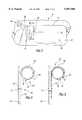
- FIG. 1is a front elevational view of a visor, partly broken away, showing the torque control of the present invention
- FIG. 2is an enlarged vertical sectional view of the torque control and the pivot rod taken along the line 2--2 of FIG. 1;
- FIG. 3is an enlarged vertical cross-sectional view of an alternative embodiment of the torque control and visor rod taken along the section line 2--2 of FIG. 1;
- FIG. 4is a front elevational view of a visor showing an alternative embodiment of the torque control of the present invention
- FIG. 5is an exploded perspective view of the pivot rod, the intermediate tube, and torque control of the alternative embodiment shown in FIG. 4;
- FIG. 6is an end view of the intermediate tube
- FIG. 7is a perspective view of the torque control in the visor shown in FIG. 4;
- FIG. 8is a plan view of the torque control of FIG. 7.
- FIG. 9is an end view of the torque control shown in FIG. 7.
- a visor 10 for a vehiclesuch as an automobile is shown.
- the visorincludes a visor body 12 typically having a butterfly core construction with two panels folded over at the top edge 13 of the visor.
- the body 12forms a hollow, light-weight and yet strong visor body covered with a suitable upholstery fabric 14 conforming the visor 10 to the interior decor of the vehicle into which it is installed.
- the visor 10may optionally include an illuminated vanity mirror assembly 16 as is known for vehicle visors.
- Torque control 20is mounted over a generally cylindrical pivot rod 18 which extends within the visor body 12 and includes an elbow terminating in a mounting bracket 19 of conventional construction for securing the visor 10 to the headliner or roof of a vehicle body.
- the torque control 20is fixedly mounted to the visor body 12 by, in one embodiment, fastening means such as rivets 17 extending through the front wall 15 of the visor body 12 to secure the torque control 20 to the visor body 12.
- fastening meanssuch as rivets 17 extending through the front wall 15 of the visor body 12 to secure the torque control 20 to the visor body 12.
- the apertures 24 of the torque control 20receive fused polymeric material for their retention of the torque control 20.
- the torque control 20allows the visor to rotate about the longitudinal axis of the pivot rod 18 and hold the visor 10 in the selected lowered use position illustrated in FIG. 1, or in a raised position against the vehicle headliner when not in use.
- the pivot rod 18can be hollow to accommodate the electrical supply conductors 31 (shown in FIG. 6) for the covered illuminated vanity mirror assembly 16.
- the torque control 20is formed of a generally rectangular spring steel member made of prehardened 0.040 gauge steel having a downwardly projecting flange 22 with apertures 24 for attaching the torque control 20 to one half of the visor body 12 as illustrated in FIG. 2.
- Torque control 20is formed to include a collar 26, which at least partially circumscribes the pivot rod 18 as seen in FIG. 2. In the preferred embodiment, the collar 26 extends approximately 270° around the pivot rod 18.
- the spring steel torque control 20integrally includes, at an end of the collar 26 remote from the flange 22, an outwardly projecting tang 28 which defines, in conjunction with flange 22, an opening slot 29 for snap-fitting the torque control 20 over the pivot rod 18 during assembly.
- a layer 32 of hardened materialforms the exterior surface of the pivot rod.
- the hardened material layer 32provides a smooth finish to the pivot rod 18 and also provides wear and abrasion resistance to the pivot rod 18 surface.
- the hardened material layer 32is a hard coat anodized material layer. Such a surface can provide excellent wear and abrasion resistance. In addition, consistent friction properties are also provided. Other surface hardening processes can be used if desired.
- the interior surface of the torque control 20 facing the rod 18, when assembled,can be coated with a polymeric material 30 as shown in FIG. 3.
- the polymeric material coating 30is provided at least in the collar area 26 although preferably, the entire interior surface of the torque control 20 is coated.
- the coating materialcan be an epoxy-based material or a polyester having from about 15-20% and preferably 17% of PTFE (Teflon®) compounded with the base polymeric material.
- the thickness of the coating 30 in the preferred embodimentis from about 0.0005 to about 0.001 inch thick with the torque control 20 being precoated prior to its forming.
- the tang 28 of the torque control 20can be compressed toward the flange 22 to increase the compression of the torque control 20 around the pivot rod 18 as desired for the level of torque required for a given visor 10.
- an intermediate tube 40is disposed over the end of the pivot rod 18.
- the intermediate tube 40also known as a slip tube, is shown in greater detail in FIGS. 5 and 6.
- the slip tube 40has an inner surface 42 which is splined with a plurality of grooves 44.
- the slip tube 40is able to telescopically engage over the end of pivot rod 18, an end portion 46 of which is provided with a splined outer surface.
- the splined outer surfaceforms ribs 48 which are received in the grooves 44 in the inner surface of the slip tube 40.
- the splined grooves 44 and the ribs 48prevent rotation of the slip tube 40 relative to the pivot rod 18.
- the slip tube 40is able to slide longitudinally along the axis of the pivot rod 18. This enables the visor body 12 to be moved longitudinally relative to the pivot rod 18 as shown by the double arrow 50 in FIG. 4.
- the end portion 46 of the pivot rod 18is preferably formed by an injection molded plastic body molded onto the core 52 of the pivot rod 18 to form the ribs 48.
- the lower groove 44 in the slip tube 40as shown in FIG. 6, has a different profile from the other three grooves 44.
- one of the ribs 48has a different profile than the others to receive the lower groove 44. This enables the rotational position of the slip tube 40 relative to the pivot rod 18 to be fixed.
- a torque control 54is disposed on the slip tube 40 and includes a generally cylindrical collar 56 and an extending flange 58.
- the visor body 60includes two injection molded plastic bracket halves 62, also know as a back bone, which sandwich an upholstered visor core 64 therebetween. Also sandwiched between the bracket halves 62 are the pivot rod 18, the slip tube 40 and the torque control 54.
- the bracket halves 62include inwardly raised walls 65 forming a pocket to receive the flange 58 of the torque control 54.
- raised plastic tabs 66extend through the aperture 68 in the torque control flange 58. The walls 65 and the tabs 66 ensure that the torque control 54 will rotate about the slip tube 40 together with the visor body 60 when the visor body 60 is rotated.
- the slip tube 40can have a cylindrical exterior surface whereby the torque control 54 holds the visor 10 in position solely by frictional forces between the torque control 54 and the slip tube 40.
- the slip tube 40is formed with two longitudinally extending flat surfaces 70 which function with the torque control 54 to provide a detent to hold the visor in a selected position, such as the raised stored position, in a manner more fully described below.
- the slip tube 40is an aluminum extrusion which is economical to produce.
- the layer 32 of hardened material on the slip tube 40is formed by hard coat anodizing the aluminum slip tube. A conventional hard coat anodizing process is used such as the anodizing process used with aluminum engine blocks. Other hard surface coatings can be used on the slip tube or torque control if desired.
- the torque control 54is formed from a generally rectangular spring steel member to integrally include the generally cylindrical collar 56 in the center portion.
- the two end portions 72 of the steel memberare joined together, such as by spot-welding, to form the flange 58 which extends generally radially outward from the collar 56.
- the collar 56is formed with a pair of spring or detent fingers 74.
- the spring fingers 74are formed in the collar 56 by a generally U-shaped cut outs 76 forming the fingers having a distal end portions 78 which can flex radially relative to the generally cylindrical collar 56.
- the distal end portions 78 of the spring fingers 74are flat to engage the flat surfaces 70 of the slip tube 40 in surface-to-surface contact.
- the flat distal end portions 78 of the spring fingers 74 and the flat surfaces 70 of the slip tube 40create a detent to provide greater retention forces to hold the visor 10 in the position where the spring finger flat end portions 78 engage the flat surfaces 70 of the slip tube 40 in surface-to-surface contact. This position is typically the raised stored position of the visor, against the vehicle headliner.
- the spring fingers 74To move the visor 10 from this position, the spring fingers 74 must deflect radially outward to move out of surface-to-surface contact with the slip tube 40 flat surfaces 70. This requires slightly greater torque to initially move the visor 10 from the stored position. In addition, as the visor 10 is returned to the stored position, the spring fingers 74 tend to "snap" the visor 10 into the stored position. This creates a detent for holding the visor 10 in the stored position. It is understood that the flat surfaces 70 of the slip tube 40 can be provided at other locations to create a detent at visor positions other than the stored position if desired.
- the aluminum slip tube 40is provided with the layer 32 of hardened material. While the layer 32 is most beneficial with the aluminum tube and the torque control 54 with the detent spring fingers, the layer 32 may be beneficial with non-detent type torque control devices as well.
Landscapes
- Engineering & Computer Science (AREA)
- Mechanical Engineering (AREA)
- Pivots And Pivotal Connections (AREA)
Abstract
Description
Claims (21)
Priority Applications (1)
| Application Number | Priority Date | Filing Date | Title |
|---|---|---|---|
| US09/099,972US5967588A (en) | 1997-04-11 | 1998-06-19 | Visor control |
Applications Claiming Priority (2)
| Application Number | Priority Date | Filing Date | Title |
|---|---|---|---|
| US08/835,998US5820197A (en) | 1997-04-11 | 1997-04-11 | Visor torque control |
| US09/099,972US5967588A (en) | 1997-04-11 | 1998-06-19 | Visor control |
Related Parent Applications (1)
| Application Number | Title | Priority Date | Filing Date |
|---|---|---|---|
| US08/835,998Continuation-In-PartUS5820197A (en) | 1997-04-11 | 1997-04-11 | Visor torque control |
Publications (1)
| Publication Number | Publication Date |
|---|---|
| US5967588Atrue US5967588A (en) | 1999-10-19 |
Family
ID=46254116
Family Applications (1)
| Application Number | Title | Priority Date | Filing Date |
|---|---|---|---|
| US09/099,972Expired - Fee RelatedUS5967588A (en) | 1997-04-11 | 1998-06-19 | Visor control |
Country Status (1)
| Country | Link |
|---|---|
| US (1) | US5967588A (en) |
Cited By (15)
| Publication number | Priority date | Publication date | Assignee | Title |
|---|---|---|---|---|
| US6296293B1 (en)* | 2000-04-28 | 2001-10-02 | Lear Corporation | Slidable auxiliary sun visor assembly |
| US6659528B1 (en)* | 2002-09-18 | 2003-12-09 | Lear Corporation | Method and apparatus for sliding and rotating a vehicle sun visor |
| US20050006923A1 (en)* | 2003-07-08 | 2005-01-13 | Johnson Controls Technology Company | Visor for a vehicle |
| US6910725B1 (en) | 2004-02-11 | 2005-06-28 | Innotec Corporation | Sliding visor |
| US20050167886A1 (en)* | 2004-01-29 | 2005-08-04 | Hiemstra David L. | Auto-indexing visor core |
| US20050236865A1 (en)* | 2004-04-23 | 2005-10-27 | Kyowa Sangyo Co., Ltd | Blow molded vehicle sun visors and methods of manufacturing such sun visors |
| US20060049655A1 (en)* | 2003-02-17 | 2006-03-09 | Johnson Controls Interiors Gmbh & Co. Kg | Device for arresting, body and arrangement comprising such a device |
| US20060087147A1 (en)* | 2004-10-22 | 2006-04-27 | Kleyn Richard A | Vehicle visor construction and method |
| US20060261627A1 (en)* | 2005-04-01 | 2006-11-23 | Johnson Controls Technology Company | Visor and method for making a visor |
| US20060267369A1 (en)* | 2005-05-13 | 2006-11-30 | Lear Corporation | Sun visor detent spring clip |
| US20060272128A1 (en)* | 2005-06-04 | 2006-12-07 | Torqmaster, Inc. | Friction hinge with angularly dependent torque |
| US20070157433A1 (en)* | 2006-01-09 | 2007-07-12 | Shin Zu Shing Co., Ltd. | Positioning hinge |
| US10864804B2 (en) | 2019-02-28 | 2020-12-15 | Irvin Automotive Products, LLC | Sliding thin visor |
| US10870337B2 (en) | 2019-02-28 | 2020-12-22 | Irvin Automotive Products, LLC | Thin visor |
| US11396220B2 (en) | 2014-12-16 | 2022-07-26 | Irvin Automotive Products, LLC | Visor |
Citations (19)
| Publication number | Priority date | Publication date | Assignee | Title |
|---|---|---|---|---|
| CA467710A (en)* | 1950-08-29 | F. L. Jacobs Co. | Sun visors | |
| US2628861A (en)* | 1947-09-29 | 1953-02-17 | Woodall Industries Inc | Sun visor |
| US3035864A (en)* | 1960-05-19 | 1962-05-22 | Howard M Davidson | Sun visor for a motor vehicle |
| US4352518A (en)* | 1979-03-05 | 1982-10-05 | Prince Corporation | Visor |
| US4489974A (en)* | 1982-09-27 | 1984-12-25 | Warhol John G | Visor assembly including friction mount |
| US4500131A (en)* | 1982-06-28 | 1985-02-19 | Prince Corporation | Visor control |
| US4582356A (en)* | 1983-12-17 | 1986-04-15 | Gebr. Happich Gmbh | Pivot bearing for sun visor for automotive vehicles |
| US4617699A (en)* | 1981-06-19 | 1986-10-21 | Nissan Motor Co., Ltd. | Hinge structure for a sun visor or the like which features a single storage position snap action function |
| US4702513A (en)* | 1984-11-09 | 1987-10-27 | Gebr. Happich Gmbh | Bracket for sun visor for automotive vehicles with means for excluding molding foam |
| US4828313A (en)* | 1987-11-02 | 1989-05-09 | Prince Corporation | Visor control |
| US4902063A (en)* | 1988-11-18 | 1990-02-20 | General Motors Corporation | Sliding sun visor |
| US4925233A (en)* | 1987-12-28 | 1990-05-15 | Prince Corporation | Adjustable visor |
| US4944549A (en)* | 1988-10-04 | 1990-07-31 | Gebr. Happich Gmbh | Sun visor for motor vehicles |
| EP0398400A2 (en)* | 1989-05-19 | 1990-11-22 | SIMAPLAST S.r.l. | Improved support means for sun visors on motor vehicles in general |
| US5139303A (en)* | 1991-07-16 | 1992-08-18 | Plasta Fiber Industries, Inc. | Sunvisor spring clip and attachment mechanism |
| US5366265A (en)* | 1992-01-15 | 1994-11-22 | Fico I.I.M.,S.A. | Spring hinge for automobile sunvisors |
| US5383700A (en)* | 1993-04-17 | 1995-01-24 | Gebr. Happich Gmbh | Position detent for sun visor for vehicles |
| US5820197A (en)* | 1997-04-11 | 1998-10-13 | Prince Corporation | Visor torque control |
| US5823603A (en)* | 1995-08-14 | 1998-10-20 | Crotty Corporation | Modular sun visor assembly and method of assembling a sun visor |
- 1998
- 1998-06-19USUS09/099,972patent/US5967588A/ennot_activeExpired - Fee Related
Patent Citations (19)
| Publication number | Priority date | Publication date | Assignee | Title |
|---|---|---|---|---|
| CA467710A (en)* | 1950-08-29 | F. L. Jacobs Co. | Sun visors | |
| US2628861A (en)* | 1947-09-29 | 1953-02-17 | Woodall Industries Inc | Sun visor |
| US3035864A (en)* | 1960-05-19 | 1962-05-22 | Howard M Davidson | Sun visor for a motor vehicle |
| US4352518A (en)* | 1979-03-05 | 1982-10-05 | Prince Corporation | Visor |
| US4617699A (en)* | 1981-06-19 | 1986-10-21 | Nissan Motor Co., Ltd. | Hinge structure for a sun visor or the like which features a single storage position snap action function |
| US4500131A (en)* | 1982-06-28 | 1985-02-19 | Prince Corporation | Visor control |
| US4489974A (en)* | 1982-09-27 | 1984-12-25 | Warhol John G | Visor assembly including friction mount |
| US4582356A (en)* | 1983-12-17 | 1986-04-15 | Gebr. Happich Gmbh | Pivot bearing for sun visor for automotive vehicles |
| US4702513A (en)* | 1984-11-09 | 1987-10-27 | Gebr. Happich Gmbh | Bracket for sun visor for automotive vehicles with means for excluding molding foam |
| US4828313A (en)* | 1987-11-02 | 1989-05-09 | Prince Corporation | Visor control |
| US4925233A (en)* | 1987-12-28 | 1990-05-15 | Prince Corporation | Adjustable visor |
| US4944549A (en)* | 1988-10-04 | 1990-07-31 | Gebr. Happich Gmbh | Sun visor for motor vehicles |
| US4902063A (en)* | 1988-11-18 | 1990-02-20 | General Motors Corporation | Sliding sun visor |
| EP0398400A2 (en)* | 1989-05-19 | 1990-11-22 | SIMAPLAST S.r.l. | Improved support means for sun visors on motor vehicles in general |
| US5139303A (en)* | 1991-07-16 | 1992-08-18 | Plasta Fiber Industries, Inc. | Sunvisor spring clip and attachment mechanism |
| US5366265A (en)* | 1992-01-15 | 1994-11-22 | Fico I.I.M.,S.A. | Spring hinge for automobile sunvisors |
| US5383700A (en)* | 1993-04-17 | 1995-01-24 | Gebr. Happich Gmbh | Position detent for sun visor for vehicles |
| US5823603A (en)* | 1995-08-14 | 1998-10-20 | Crotty Corporation | Modular sun visor assembly and method of assembling a sun visor |
| US5820197A (en)* | 1997-04-11 | 1998-10-13 | Prince Corporation | Visor torque control |
Cited By (19)
| Publication number | Priority date | Publication date | Assignee | Title |
|---|---|---|---|---|
| US6296293B1 (en)* | 2000-04-28 | 2001-10-02 | Lear Corporation | Slidable auxiliary sun visor assembly |
| US6659528B1 (en)* | 2002-09-18 | 2003-12-09 | Lear Corporation | Method and apparatus for sliding and rotating a vehicle sun visor |
| US20060049655A1 (en)* | 2003-02-17 | 2006-03-09 | Johnson Controls Interiors Gmbh & Co. Kg | Device for arresting, body and arrangement comprising such a device |
| US7171112B2 (en)* | 2003-02-17 | 2007-01-30 | Johnson Controls Interiors Gmbh & Co. Kg | Visor adjustment device |
| US20050006923A1 (en)* | 2003-07-08 | 2005-01-13 | Johnson Controls Technology Company | Visor for a vehicle |
| US20050167886A1 (en)* | 2004-01-29 | 2005-08-04 | Hiemstra David L. | Auto-indexing visor core |
| US7556759B2 (en) | 2004-01-29 | 2009-07-07 | Hiemstra David L | Auto-indexing visor core |
| US6910725B1 (en) | 2004-02-11 | 2005-06-28 | Innotec Corporation | Sliding visor |
| US20050236865A1 (en)* | 2004-04-23 | 2005-10-27 | Kyowa Sangyo Co., Ltd | Blow molded vehicle sun visors and methods of manufacturing such sun visors |
| US7213865B2 (en)* | 2004-04-23 | 2007-05-08 | Kyowa Sangyo Co., Ltd. | Blow molded vehicle sun visors and methods of manufacturing such sun visors |
| US7152901B2 (en) | 2004-10-22 | 2006-12-26 | Innotec Corporation | Vehicle visor construction and method |
| US20060087147A1 (en)* | 2004-10-22 | 2006-04-27 | Kleyn Richard A | Vehicle visor construction and method |
| US20060261627A1 (en)* | 2005-04-01 | 2006-11-23 | Johnson Controls Technology Company | Visor and method for making a visor |
| US20060267369A1 (en)* | 2005-05-13 | 2006-11-30 | Lear Corporation | Sun visor detent spring clip |
| US20060272128A1 (en)* | 2005-06-04 | 2006-12-07 | Torqmaster, Inc. | Friction hinge with angularly dependent torque |
| US20070157433A1 (en)* | 2006-01-09 | 2007-07-12 | Shin Zu Shing Co., Ltd. | Positioning hinge |
| US11396220B2 (en) | 2014-12-16 | 2022-07-26 | Irvin Automotive Products, LLC | Visor |
| US10864804B2 (en) | 2019-02-28 | 2020-12-15 | Irvin Automotive Products, LLC | Sliding thin visor |
| US10870337B2 (en) | 2019-02-28 | 2020-12-22 | Irvin Automotive Products, LLC | Thin visor |
Similar Documents
| Publication | Publication Date | Title |
|---|---|---|
| US5967588A (en) | Visor control | |
| US5967587A (en) | Sliding visor | |
| US5645308A (en) | Sliding visor | |
| US5820197A (en) | Visor torque control | |
| US6174019B1 (en) | Extruded visor control | |
| US5636891A (en) | Adjustable fastener | |
| US4925233A (en) | Adjustable visor | |
| US20020089217A1 (en) | Vehicle accessory with sliding cover | |
| US7823954B2 (en) | Slidable visor assembly | |
| US4352518A (en) | Visor | |
| US6220644B1 (en) | Visor assembly | |
| US6494521B2 (en) | Head impact energy absorbing sun visor pivot rod connection interface cover | |
| US5871252A (en) | Telescopic sunvisor | |
| US6547308B2 (en) | Visor mounting assembly | |
| US7000972B2 (en) | Sun visor for use with vehicles | |
| US5765899A (en) | Lockable sliding visor | |
| US7036877B2 (en) | Modular mounting assembly | |
| US5544927A (en) | Twist-in visor mount | |
| US12077089B2 (en) | Position clutch ring system | |
| US6409246B1 (en) | Snap-in hinged visor extender | |
| US5431473A (en) | Mirror cover and visor extender | |
| US6719352B2 (en) | Visor mounting assembly | |
| US7281751B2 (en) | Sliding visor | |
| US20080093876A1 (en) | Visor for a Vehicle | |
| US5280988A (en) | Multi-pivoting arrangement for visor |
Legal Events
| Date | Code | Title | Description |
|---|---|---|---|
| AS | Assignment | Owner name:PRINCE CORPORATION, MICHIGAN Free format text:ASSIGNMENT OF ASSIGNORS INTEREST;ASSIGNORS:COLLET, CORBIN L.;KREUZE, KENNETH D.;LANSER, MICHAEL L.;REEL/FRAME:009448/0234;SIGNING DATES FROM 19980728 TO 19980806 | |
| CC | Certificate of correction | ||
| FEPP | Fee payment procedure | Free format text:PAYOR NUMBER ASSIGNED (ORIGINAL EVENT CODE: ASPN); ENTITY STATUS OF PATENT OWNER: LARGE ENTITY | |
| FPAY | Fee payment | Year of fee payment:4 | |
| FPAY | Fee payment | Year of fee payment:8 | |
| REMI | Maintenance fee reminder mailed | ||
| LAPS | Lapse for failure to pay maintenance fees | ||
| STCH | Information on status: patent discontinuation | Free format text:PATENT EXPIRED DUE TO NONPAYMENT OF MAINTENANCE FEES UNDER 37 CFR 1.362 | |
| FP | Lapsed due to failure to pay maintenance fee | Effective date:20111019 | |
| AS | Assignment | Owner name:CIBC BANK USA, ILLINOIS Free format text:SECURITY INTEREST;ASSIGNOR:INNOTEC, CORP.;REEL/FRAME:054290/0669 Effective date:20201030 | |
| AS | Assignment | Owner name:INNOTEC, CORP., MICHIGAN Free format text:RELEASE BY SECURED PARTY;ASSIGNOR:CIBC BANK USA;REEL/FRAME:066434/0140 Effective date:20240131 |