US5967497A - Highway barrier and guardrail - Google Patents
Highway barrier and guardrailDownload PDFInfo
- Publication number
- US5967497A US5967497AUS08/990,468US99046897AUS5967497AUS 5967497 AUS5967497 AUS 5967497AUS 99046897 AUS99046897 AUS 99046897AUS 5967497 AUS5967497 AUS 5967497A
- Authority
- US
- United States
- Prior art keywords
- support post
- plate
- guardrail
- transferring members
- load transferring
- Prior art date
- Legal status (The legal status is an assumption and is not a legal conclusion. Google has not performed a legal analysis and makes no representation as to the accuracy of the status listed.)
- Expired - Fee Related
Links
- 230000004888barrier functionEffects0.000titleclaimsdescription35
- 239000002184metalSubstances0.000claimsabstractdescription8
- 230000003466anti-cipated effectEffects0.000claims3
- 230000003116impacting effectEffects0.000description8
- 229910000831SteelInorganic materials0.000description2
- 239000010959steelSubstances0.000description2
- 239000002023woodSubstances0.000description2
- 238000005452bendingMethods0.000description1
- 238000009434installationMethods0.000description1
- 239000000463materialSubstances0.000description1
- 230000004048modificationEffects0.000description1
- 238000012986modificationMethods0.000description1
Images


Classifications
- E—FIXED CONSTRUCTIONS
- E01—CONSTRUCTION OF ROADS, RAILWAYS, OR BRIDGES
- E01F—ADDITIONAL WORK, SUCH AS EQUIPPING ROADS OR THE CONSTRUCTION OF PLATFORMS, HELICOPTER LANDING STAGES, SIGNS, SNOW FENCES, OR THE LIKE
- E01F15/00—Safety arrangements for slowing, redirecting or stopping errant vehicles, e.g. guard posts or bollards; Arrangements for reducing damage to roadside structures due to vehicular impact
- E01F15/14—Safety arrangements for slowing, redirecting or stopping errant vehicles, e.g. guard posts or bollards; Arrangements for reducing damage to roadside structures due to vehicular impact specially adapted for local protection, e.g. for bridge piers, for traffic islands
- E01F15/143—Protecting devices located at the ends of barriers
- E—FIXED CONSTRUCTIONS
- E01—CONSTRUCTION OF ROADS, RAILWAYS, OR BRIDGES
- E01F—ADDITIONAL WORK, SUCH AS EQUIPPING ROADS OR THE CONSTRUCTION OF PLATFORMS, HELICOPTER LANDING STAGES, SIGNS, SNOW FENCES, OR THE LIKE
- E01F15/00—Safety arrangements for slowing, redirecting or stopping errant vehicles, e.g. guard posts or bollards; Arrangements for reducing damage to roadside structures due to vehicular impact
- E01F15/02—Continuous barriers extending along roads or between traffic lanes
- E01F15/04—Continuous barriers extending along roads or between traffic lanes essentially made of longitudinal beams or rigid strips supported above ground at spaced points
- E01F15/0476—Foundations
Definitions
- This inventionrelates to highway barriers that include guardrails extending along side a roadway, and to guardrails suitable for use in such a barrier.
- Sicking U.S. Pat. No. 5,407,298 and Mak U.S. Pat. No. 5,547,309disclose highway barriers including slotted guardrails.
- the guardrailsare conventional steel beams having a W-shape in cross-section.
- Such a guardrailis well adapted to redirect an automobile after it has left a roadway, but it can provide excessive rigidity against column loads.
- Such excessive rigiditycan result in a tendency of the guardrail to spear an axially impacting vehicle.
- the guardrail disclosed in the Sicking '298 and Mak '309 patentsincludes longitudinally extending slots that reduce the maximum column load that can be supported by the guardrail.
- Mak U.S. Pat. No. 5,503,495discloses a guardrail cable release mechanism designed for use with a breakaway support post.
- the cable release mechanismincludes a plate that defines a parallel-sided notch and a V-shaped entrance to the notch. This plate is placed between the threaded nut at the end of the barrier cable and the first breakaway support post. When the breakaway support post is broken in an axial impact, the cable moves out of the notch and V-shaped opening to disengage from the release mechanism.
- a potential problem associated with the guardrail cable release mechanism of the Mak '495 patentis that the slotted bearing plate might not release as quickly as desired when the breakaway support post is broken in an axial impact, particularly if the support post were to break at an oblique angle to the horizontal.
- the preferred embodiments described belowinclude a highway guardrail that has weakened regions such as slots, holes, thinned regions, crimps or dents that are oriented obliquely to the longitudinal direction of the guardrail.
- weakened regionsform one or more elongated fold regions at which the guardrail tends to buckle predictably when a sufficiently large column load is applied, as for example, when struck by an axially impacting vehicle.
- the fold regionsare oriented obliquely to the longitudinal direction of the guardrail such that the rearward portion of the guardrail has a reduced tendency to move upwardly as the guardrail buckles.
- the guardrailis secured by a tension member (such as a cable) to a support post.
- First and second load transferring membersform a split washer that is interposed between an enlarged portion of the tension member and the support post. These load transferring members extend on opposite sides of the tension member and are positioned to prevent the enlarged portion of the tension member from passing between the load transferring members. The load transferring members readily separate from one another to release the tension member after the support post breaks in an axial impact.
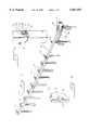
- FIGS. 1, 2 and 3are isometric, elevation and plan views, respectively, of a highway barrier that incorporates presently preferred embodiments of the present invention.
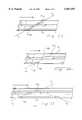
- FIG. 4is an elevation view of the forwardmost guardrail plate of the embodiment of FIGS. 1 through 3, prior to assembly.
- FIG. 5is an elevation view of the guardrail plate that is disposed immediately rearwardly of the guardrail plate of FIG. 4 in the embodiment of FIGS. 1 through 3, prior to assembly.
- FIG. 6is an isometric view of a support post suitable for use at the forward portion of the embodiment of FIGS. 1 through 3.
- FIG. 7is an isometric view of a support post suitable for use rearwardly of the support post of FIG. 6 in the embodiment of FIGS. 1 through 3.
- FIG. 8is a fragmentary perspective view showing the forward support post of the embodiment of FIGS. 1 through 3.
- FIG. 9is an isometric view of one of the load transferring members of FIG. 8.
- FIGS. 10 through 14are isometric views of alternative embodiments of weakened regions suitable for defining a fold region in guardrail panels of alternative embodiments.
- FIG. 15is an isometric view of a guardrail panel including weakened regions for defining two fold regions.
- FIGS. 1 through 3show various views of a highway barrier 10 that incorporates preferred embodiments of this invention.
- the barrier 10includes a guardrail 12 made up of a plurality of guardrail plates 14, 16, and 18.
- the guardrail plates 14, 16, 18are sufficiently rigid to deflect an automotive vehicle in many cases.
- the guardrail plates 14, 16, 18may be formed of a W-beam of 12-gauge steel, and the W-beam may be shaped as defined in AASHTO specification M18D-89, class A, type 3.
- the guardrail 12is supported above ground level by support posts including front support posts 20 and intermediate support posts 22.
- the highway barrier 10is positioned alongside a roadway R, and includes an end section 24 that is buffered to reduce any tendency of the highway barrier 10 to spear an impacting vehicle traveling in the longitudinal direction L.
- the forward section 32 of the highway barrier 10curves away from the roadway R.
- a strut 26is positioned between the front support posts 20 in the conventional manner.
- a tension membersuch as a cable 28 is secured to the guardrail plate 14 between the front support posts 20. The forward end of this cable 28 passes through an opening in the forward support post 20 as described below.
- FIG. 4shows an elevation view of the guardrail plate 14.
- the forward portion of the guardrail plate 14 that supports the end section 24is positioned to the left.
- An array of holes 42is formed in the forward end of the guardrail plate 14 to receive bolts (not shown in FIG. 4) that secure the guardrail plate 14 and the end section 24.
- Holes 44are provided for securing an anchor plate (not shown in FIG. 4) that engages the rearward end of the cable 28 (not shown in FIG. 4) in the conventional manner.
- Rearward holes 46allow the guardrail plate 14 to be bolted to the guardrail plate 16 of FIGS. 1 through 3.
- slots 40are provided to weaken the guardrail plate 14 and to dispose it for column buckling when subjected to substantial column loads in an axial impact.
- the slots 40measure approximately 19 by 178 mm, and are centered in the valley and on the ridges of the guardrail plate 14.
- the slots 40can be replaced with other means for preventing the plate 14 from spearing an impacting vehicle, such as an array of openings, for example.
- FIG. 5shows an elevation view of the guardrail plate 16.
- the plate 16includes forward and rearward holes 50, 52 positioned to receive fasteners that secure the guardrail plate 16 to the guardrail plates 14 and 18, respectively.
- the guardrail plate 16also includes weakened regions 54 that form a fold region 56 oriented obliquely with respect to the longitudinal direction L.
- the weakened regions 54are formed by upsets positioned on the edges of the guardrail plate 16. These upsets are staggered along the length of the guardrail plate 16 and are positioned along a fold axis A that is obliquely oriented at an angle ⁇ of about 30° with respect to the longitudinal direction L of the guardrail plate 16.
- First and second portions 58, 60 of the guardrail plate 16are positioned forwardly and rearwardly of the fold axis A, respectively. Because the lower weakened region 54 is positioned forwardly of the upper weakened region 54, the second portion 60 tends to move downwardly when the guard rail plate 16 collapses under extreme axial loading associated with an axially impacting vehicle. In this way, the highway barrier 10 is provided with a preferred direction of folding or collapse, which has been designed to maintain the fold region 56 of the guardrail plate 16 near the ground and to assist in controlling the direction of travel of the decelerating impacting vehicle as the highway barrier 10 responds to the impact.
- the guardrail 12is secured to the support posts 20, 22 only at the first, fifth and tenth support posts, as counted from the end section 24.
- the weakened regions 54are preferably positioned between posts 6 and 7 and optionally between posts 3 and 4.
- FIG. 6shows an isometric view of one of the front support posts 20 suitable for use in the first and second positions of the highway barrier 10.
- Each front support post 20includes a slot 70 and a through-hole 72.
- the slotis about 10 mm in width and 610 mm in length, and the hole 72 is about 61 mm in diameter.
- Each front support post 20is preferably formed of wood, and the slot 70 is provided to reduce the force required to break the post 20 at the hole 72 in an axial impact.
- FIG. 7shows an isometric view of one of the intermediate support posts 22 that in this embodiment are also made of wood and are used at positions 3 through 11 as counted from the front of the highway barrier 10.
- Each intermediate support post 22includes two holes 74 that are about 51 mm in diameter.
- FIGS. 8 and 9provide further details regarding the manner in which the forward end of the cable 28 is secured to the first front support post 20.
- the forward end of the cable 28includes a threaded end 80 that receives a nut 82 and a washer 84.
- the nut 82 and the washer 84cooperate to form an enlarged portion of the cable 28 having a first area.
- the enlarged portioncan be swaged or otherwise permanently formed on or releasably secured to the end of the cable 28.
- a split washer 86is interposed between the washer 84 and the post 20. This split washer 86 is formed of two load transferring members 88 that have a combined cross-sectional area adjacent to the post 20 that is greater than the first area of the washer 84.
- the load transferring members 88perform a load-spreading function.
- each of the load transferring members 88includes a first part 90 that lies alongside the post 20 and a second part 92 dimensioned to fit into the hole 72 (FIG. 8).
- the first and second parts 90, 92preferably define a notch 93 to partially receive the cable.
- each of the load transferring membersis positioned entirely on a respective side of a vertical plane passing through the center of the cable 28, and the gap between the load transferring members 88 is preferably oriented vertically.
- the impacting vehiclewill break the support post 20 at the hole 72. This will allow the load transferring members 88 to move away from one another, thereby releasing the threaded end 80 of the cable 28, including the nut 82 and the washer 84.
- FIGS. 10 through 14Each of these figures shows an isometric view of an alternative form of the guard rail plate 16, and in each case the fold axis is indicated by the reference symbol A.
- FIGS. 10-14the front of the guardrail plate 16 is to the left, and the weakened regions are near the front end of the plate 16.
- the weakened regionsare formed by circular holes 100. Because the circular holes 100 are formed on the uppermost portion of the ridges and the lowermost portion of the central valley, they do not appear colinear in the isometric view of FIG. 10, but they would appear colinear in elevation.
- the weakened regionsare formed by slots 102, and non-circular holes 104, respectively.
- the weakened regionsmay be formed by one or more crimps 106, and in FIG. 14 the weakened regions are formed by a combination if holes 108 and crimps 110.
- the weakened regionsmay correspond to thinned regions of the guardrail plate.
- this inventionis not limited to use with W-beams that define two ridges extending longitudinally of the beam. Rather, this invention can be adapted for use with the widest variety of guard rail plates, including those having one, two, three or more longitudinally extending ridges, as well as box sections.
- the tension memberis not limited to the cable form illustrated above; rather any suitable structure for transmitting tensile loads, including metal straps, rods, chains and the like can be used.
- the load transferring membersmay be shaped differently than illustrated, and the second part 92 may extend more deeply into the opening 72. If desired, notches 93 can be eliminated in the first and second parts 90, 92.
- the postscan be formed of any suitable material.
- the fold regiondoes not have to be shaped as a straight line and it can be positioned and shaped as appropriate for the particular application.
- the fold regioncan be defined from dissimilar weakened regions.
- a fold regioncan be defined by the combination of a circular hole, a non-circular hole, and a crimp.
- the weakened regionsmay extend partially or completely across the guardrail panel.
- the weakened regionsmay be oriented at other oblique (non-perpendicular) directions with respect to the longitudinal direction, such as 45° for example.
- FIG. 15shows a view of a guardrail plate 16 on which two fold axes, A and B, are defined by perforations in the guardrail plate aligned along the fold axes when viewed in elevation.
- guardrail plates described abovecan be used in a wide variety of barriers, including simple guardrail barriers, converging guardrail barriers, and energy absorbing barriers. Though shown in use at a forward portion of a guardrail barrier, these guardrail plates can be used at any desired point along the length of the guardrail barrier. Similarly, the load transferring members can be used at other support posts than the forwardmost post illustrated.
Landscapes
- Engineering & Computer Science (AREA)
- Architecture (AREA)
- Civil Engineering (AREA)
- Structural Engineering (AREA)
- Refuge Islands, Traffic Blockers, Or Guard Fence (AREA)
Abstract
Description
Claims (35)
Priority Applications (7)
| Application Number | Priority Date | Filing Date | Title |
|---|---|---|---|
| US08/990,468US5967497A (en) | 1997-12-15 | 1997-12-15 | Highway barrier and guardrail |
| NZ332805ANZ332805A (en) | 1997-12-15 | 1998-11-13 | Guardrail comprising elongate metal plate with weakened sections and tension member with washer made up of two separate halves |
| EP98309410AEP0924348A3 (en) | 1997-12-15 | 1998-11-17 | Highway barrier and guardrail |
| MYPI98005617AMY116307A (en) | 1997-12-15 | 1998-12-11 | Highway barrier and guardrail |
| AU97114/98AAU742837B2 (en) | 1997-12-15 | 1998-12-14 | Highway barrier and guardrail |
| NO985847ANO985847L (en) | 1997-12-15 | 1998-12-14 | Highway fence and guard rail |
| US09/344,149US6142452A (en) | 1997-12-15 | 1999-06-24 | Highway barrier and guardrail |
Applications Claiming Priority (1)
| Application Number | Priority Date | Filing Date | Title |
|---|---|---|---|
| US08/990,468US5967497A (en) | 1997-12-15 | 1997-12-15 | Highway barrier and guardrail |
Related Child Applications (1)
| Application Number | Title | Priority Date | Filing Date |
|---|---|---|---|
| US09/344,149DivisionUS6142452A (en) | 1997-12-15 | 1999-06-24 | Highway barrier and guardrail |
Publications (1)
| Publication Number | Publication Date |
|---|---|
| US5967497Atrue US5967497A (en) | 1999-10-19 |
Family
ID=25536183
Family Applications (2)
| Application Number | Title | Priority Date | Filing Date |
|---|---|---|---|
| US08/990,468Expired - Fee RelatedUS5967497A (en) | 1997-12-15 | 1997-12-15 | Highway barrier and guardrail |
| US09/344,149Expired - Fee RelatedUS6142452A (en) | 1997-12-15 | 1999-06-24 | Highway barrier and guardrail |
Family Applications After (1)
| Application Number | Title | Priority Date | Filing Date |
|---|---|---|---|
| US09/344,149Expired - Fee RelatedUS6142452A (en) | 1997-12-15 | 1999-06-24 | Highway barrier and guardrail |
Country Status (6)
| Country | Link |
|---|---|
| US (2) | US5967497A (en) |
| EP (1) | EP0924348A3 (en) |
| AU (1) | AU742837B2 (en) |
| MY (1) | MY116307A (en) |
| NO (1) | NO985847L (en) |
| NZ (1) | NZ332805A (en) |
Cited By (30)
| Publication number | Priority date | Publication date | Assignee | Title |
|---|---|---|---|---|
| US6173943B1 (en)* | 1998-04-22 | 2001-01-16 | Energy Absorption Systems, Inc. | Guardrail with slidable impact-receiving element |
| US6290427B1 (en)* | 1999-02-16 | 2001-09-18 | Carlos M. Ochoa | Guardrail beam with enhanced stability |
| EP1167629A2 (en) | 2000-06-29 | 2002-01-02 | Energy Absorption Systems, Inc. | Highway crash barrier monitoring system |
| US6533249B2 (en) | 1999-09-23 | 2003-03-18 | Icom Engineering, Inc. | Guardrail beam with improved edge region and method of manufacture |
| US6554256B2 (en) | 2001-04-25 | 2003-04-29 | Icom Engineering, Inc. | Highway guardrail end terminal assembly |
| US20030165356A1 (en)* | 1997-11-24 | 2003-09-04 | Breed David S. | Roadside barrier |
| US20040016916A1 (en)* | 2002-06-19 | 2004-01-29 | Trn Business Trust | Crash cushions and other energy absorbing devices |
| US6719483B1 (en)* | 1998-11-27 | 2004-04-13 | Anders Welandsson | Collision safety device |
| WO2005028757A1 (en)* | 2003-09-22 | 2005-03-31 | Armorflex Limited | Guardrail |
| US20050284695A1 (en)* | 2002-05-28 | 2005-12-29 | Trn Business Trust | Cable safety system |
| US20060093430A1 (en)* | 2004-10-28 | 2006-05-04 | Peter Bergendahl | Combined guardrail and cable safety systems |
| US7059590B2 (en) | 2002-06-19 | 2006-06-13 | Trn Business Trust | Impact assembly for an energy absorbing device |
| US20090050863A1 (en)* | 2007-08-21 | 2009-02-26 | Nucor Corporation | Roadway guardrail system |
| US20090050864A1 (en)* | 2007-08-21 | 2009-02-26 | Nucor Corporation | Roadway guardrail system |
| US20090121205A1 (en)* | 2006-05-04 | 2009-05-14 | Armorflex Limited | Releaseable anchor cables for cable barriers that release upon certain load conditions upon the cable barrier |
| US20090218554A1 (en)* | 2008-02-08 | 2009-09-03 | Nucor Corporation | Cable guardrail system and hanger |
| US20090302288A1 (en)* | 2008-06-04 | 2009-12-10 | Dallas James | Guardrail |
| US20100090185A1 (en)* | 2008-10-13 | 2010-04-15 | Nucor Corporation | Roadway guardrail system and hanger |
| US7712345B1 (en)* | 2007-05-29 | 2010-05-11 | Chun-Liang Chen | Main beam fabrication procedure and system for making a main beam for warehouse framework |
| US20100192482A1 (en)* | 2007-07-27 | 2010-08-05 | Dallas Rex James | Frangible posts |
| US20100207087A1 (en)* | 2006-11-06 | 2010-08-19 | Dallas James | Impact energy dissipation system |
| US20100215427A1 (en)* | 2007-06-01 | 2010-08-26 | Dallas James | barrier section connection system |
| US20100243978A1 (en)* | 2009-03-31 | 2010-09-30 | Leonhardt Patrick A | Guardrail assembly, breakaway support post for a guardrail and methods for the assembly and use thereof |
| GB2492078A (en)* | 2011-06-20 | 2012-12-26 | Safer Highways Ltd | Highway barrier |
| US8905382B2 (en) | 2011-02-01 | 2014-12-09 | Energy Absorption Systems, Inc. | End terminal |
| US20150292169A1 (en)* | 2011-06-09 | 2015-10-15 | Axip Limited | Energy absorbing apparatus |
| US10047488B2 (en) | 2012-10-24 | 2018-08-14 | Energy Absorption Systems, Inc. | Frangible post for highway barrier end terminals |
| US20180238003A1 (en)* | 2017-02-23 | 2018-08-23 | Lindsay Transportation Solutions, Inc. | Guardrail crash absorbing assembly |
| US10202730B2 (en) | 2005-07-06 | 2019-02-12 | Gibraltar Global, Llc | Roadway cable barrier system |
| US11970826B2 (en) | 2020-06-05 | 2024-04-30 | Valtir, LLC | Crash cushion |
Families Citing this family (15)
| Publication number | Priority date | Publication date | Assignee | Title |
|---|---|---|---|---|
| US6799278B2 (en) | 2000-12-21 | 2004-09-28 | Dell Products, L.P. | System and method for processing power management signals in a peer bus architecture |
| US6797748B2 (en) | 2001-06-08 | 2004-09-28 | Bic Corporation | Polyurethane based inks for writing instruments |
| ITTO20020620A1 (en)* | 2002-07-16 | 2004-01-16 | Fracasso Metalmeccanica | ROAD BARRIER TERMINAL |
| US20040262588A1 (en)* | 2003-06-27 | 2004-12-30 | Trn Business Trust | Variable width crash cushions and end terminals |
| US6962459B2 (en)* | 2003-08-12 | 2005-11-08 | Sci Products Inc. | Crash attenuator with cable and cylinder arrangement for decelerating vehicles |
| US7243908B2 (en) | 2004-04-07 | 2007-07-17 | The Texas A&M Univeristy System | Cable anchor bracket |
| FR2876715B1 (en)* | 2004-10-19 | 2006-12-15 | Profiles Du Ct Sa | PROTECTIVE TIP FOR ROAD SAFETY SLIDER SCREEN |
| US20070102689A1 (en)* | 2005-11-08 | 2007-05-10 | Alberson Dean C | Cable barrier guardrail system with steel yielding support posts |
| GB2439081A (en)* | 2006-06-13 | 2007-12-19 | Corus Uk Ltd | Vehicle safety barrier with angled anchor construction |
| US7694941B2 (en)* | 2008-05-05 | 2010-04-13 | The Texas A&M University System | Guardrail safety system for dissipating energy to decelerate the impacting vehicle |
| US7883075B2 (en)* | 2008-05-05 | 2011-02-08 | The Texas A&M University System | Tension guardrail terminal |
| DK176759B1 (en)* | 2008-08-12 | 2009-06-29 | Thomas Willum Jensen | Car guard with shock absorbing measures |
| AU2011205073B2 (en) | 2010-08-12 | 2015-02-12 | Valmont Highway Technology Limited | Improvements in and Relating to Barriers |
| CN102477729A (en)* | 2010-11-29 | 2012-05-30 | 张家港港丰交通安全设施有限公司 | Clamping type highway guardrail |
| US9051699B2 (en) | 2013-01-22 | 2015-06-09 | Fletcher Building Holdings Limited | Pedestrian and vehicle barrier |
Citations (10)
| Publication number | Priority date | Publication date | Assignee | Title |
|---|---|---|---|---|
| US1332626A (en)* | 1919-03-26 | 1920-03-02 | James E Henegar | Self-locking washer |
| US1492561A (en)* | 1920-11-17 | 1924-05-06 | Sectional Gap Washer Corp | Washer or shim |
| US1558364A (en)* | 1923-07-16 | 1925-10-20 | Elmer J Iverson | Washer |
| US2047436A (en)* | 1934-08-20 | 1936-07-14 | Sheffield Steel Corp | Highway guard |
| FR2607841A1 (en)* | 1986-12-09 | 1988-06-10 | Profilafroid Sa | Crash barrier |
| US5407298A (en)* | 1993-06-15 | 1995-04-18 | The Texas A&M University System | Slotted rail terminal |
| US5503495A (en)* | 1993-06-15 | 1996-04-02 | The Texas A & M University System | Thrie-beam terminal with breakaway post cable release |
| US5660496A (en)* | 1995-04-19 | 1997-08-26 | Snoline S.P.A. | Modular construction road barrier suitable to gradually absorb the impact energy of vehicles |
| US5765811A (en)* | 1997-03-18 | 1998-06-16 | Alberson; Dean C. | Guardrail terminal |
| US5821005A (en)* | 1995-03-08 | 1998-10-13 | Sharp Kabushiki Kaisha | Ferroelectrics thin-film coated substrate and manufacture method thereof and nonvolatile memory comprising a ferroelectrics thinfilm coated substrate |
Family Cites Families (3)
| Publication number | Priority date | Publication date | Assignee | Title |
|---|---|---|---|---|
| FR2282504A1 (en)* | 1974-08-21 | 1976-03-19 | Angel Gilbert | Corrugated vehicle impact barrier - has tie bars linking adjacent peaks to raise yield tension |
| US4928928A (en)* | 1988-01-12 | 1990-05-29 | The Texas A&M University System | Guardrail extruder terminal |
| US4838523A (en)* | 1988-07-25 | 1989-06-13 | Syro Steel Company | Energy absorbing guard rail terminal |
- 1997
- 1997-12-15USUS08/990,468patent/US5967497A/ennot_activeExpired - Fee Related
- 1998
- 1998-11-13NZNZ332805Apatent/NZ332805A/enunknown
- 1998-11-17EPEP98309410Apatent/EP0924348A3/ennot_activeWithdrawn
- 1998-12-11MYMYPI98005617Apatent/MY116307A/enunknown
- 1998-12-14AUAU97114/98Apatent/AU742837B2/ennot_activeCeased
- 1998-12-14NONO985847Apatent/NO985847L/ennot_activeApplication Discontinuation
- 1999
- 1999-06-24USUS09/344,149patent/US6142452A/ennot_activeExpired - Fee Related
Patent Citations (11)
| Publication number | Priority date | Publication date | Assignee | Title |
|---|---|---|---|---|
| US1332626A (en)* | 1919-03-26 | 1920-03-02 | James E Henegar | Self-locking washer |
| US1492561A (en)* | 1920-11-17 | 1924-05-06 | Sectional Gap Washer Corp | Washer or shim |
| US1558364A (en)* | 1923-07-16 | 1925-10-20 | Elmer J Iverson | Washer |
| US2047436A (en)* | 1934-08-20 | 1936-07-14 | Sheffield Steel Corp | Highway guard |
| FR2607841A1 (en)* | 1986-12-09 | 1988-06-10 | Profilafroid Sa | Crash barrier |
| US5407298A (en)* | 1993-06-15 | 1995-04-18 | The Texas A&M University System | Slotted rail terminal |
| US5503495A (en)* | 1993-06-15 | 1996-04-02 | The Texas A & M University System | Thrie-beam terminal with breakaway post cable release |
| US5547309A (en)* | 1993-06-15 | 1996-08-20 | The Texas A&M University System | Thrie-beam terminal with breakaway post cable release |
| US5821005A (en)* | 1995-03-08 | 1998-10-13 | Sharp Kabushiki Kaisha | Ferroelectrics thin-film coated substrate and manufacture method thereof and nonvolatile memory comprising a ferroelectrics thinfilm coated substrate |
| US5660496A (en)* | 1995-04-19 | 1997-08-26 | Snoline S.P.A. | Modular construction road barrier suitable to gradually absorb the impact energy of vehicles |
| US5765811A (en)* | 1997-03-18 | 1998-06-16 | Alberson; Dean C. | Guardrail terminal |
Cited By (68)
| Publication number | Priority date | Publication date | Assignee | Title |
|---|---|---|---|---|
| US20030165356A1 (en)* | 1997-11-24 | 2003-09-04 | Breed David S. | Roadside barrier |
| US7819604B2 (en)* | 1997-11-24 | 2010-10-26 | Automotive Technologies International, Inc. | Roadside barrier |
| US6173943B1 (en)* | 1998-04-22 | 2001-01-16 | Energy Absorption Systems, Inc. | Guardrail with slidable impact-receiving element |
| US6719483B1 (en)* | 1998-11-27 | 2004-04-13 | Anders Welandsson | Collision safety device |
| US6830407B1 (en) | 1999-02-16 | 2004-12-14 | Icom Engineering, Inc. | Guardrail beam with enhanced stability |
| US6290427B1 (en)* | 1999-02-16 | 2001-09-18 | Carlos M. Ochoa | Guardrail beam with enhanced stability |
| US6558067B2 (en) | 1999-02-16 | 2003-05-06 | Icom Engineering, Inc. | Guardrail beam with enhanced stability |
| US6533249B2 (en) | 1999-09-23 | 2003-03-18 | Icom Engineering, Inc. | Guardrail beam with improved edge region and method of manufacture |
| EP1167629A2 (en) | 2000-06-29 | 2002-01-02 | Energy Absorption Systems, Inc. | Highway crash barrier monitoring system |
| US6539175B1 (en) | 2000-06-29 | 2003-03-25 | Energy Absorption Systems, Inc. | Highway crash barrier monitoring system |
| US6554256B2 (en) | 2001-04-25 | 2003-04-29 | Icom Engineering, Inc. | Highway guardrail end terminal assembly |
| US20050284695A1 (en)* | 2002-05-28 | 2005-12-29 | Trn Business Trust | Cable safety system |
| US6854716B2 (en) | 2002-06-19 | 2005-02-15 | Trn Business Trust | Crash cushions and other energy absorbing devices |
| US20040016916A1 (en)* | 2002-06-19 | 2004-01-29 | Trn Business Trust | Crash cushions and other energy absorbing devices |
| US7059590B2 (en) | 2002-06-19 | 2006-06-13 | Trn Business Trust | Impact assembly for an energy absorbing device |
| WO2005028757A1 (en)* | 2003-09-22 | 2005-03-31 | Armorflex Limited | Guardrail |
| AU2004274835B2 (en)* | 2003-09-22 | 2010-09-16 | Australian Construction Products Pty Limited | Guardrail |
| US20090065754A1 (en)* | 2003-09-22 | 2009-03-12 | Dallas James | Impact slider for guardrail |
| US20070131918A1 (en)* | 2003-09-22 | 2007-06-14 | Armorflex Limited | Guardrail |
| US7926790B2 (en) | 2003-09-22 | 2011-04-19 | Axip Limited | Impact slider for guardrail |
| US7699293B2 (en) | 2003-09-22 | 2010-04-20 | Armorflex Limited | Guardrail |
| US8177194B2 (en) | 2003-09-22 | 2012-05-15 | Axip Limited | Frangible post for guardrail |
| US20060182495A1 (en)* | 2004-10-28 | 2006-08-17 | Trn Business Trust | Combined guardrail and cable safety systems |
| US7544009B2 (en)* | 2004-10-28 | 2009-06-09 | Trinity Industries, Inc. | Combined guardrail and cable safety systems |
| US7686535B2 (en)* | 2004-10-28 | 2010-03-30 | Trinity Industries, Inc. | Combined guardrail and cable safety systems |
| US8157471B2 (en) | 2004-10-28 | 2012-04-17 | Trinity Industries, Inc. | Combined guardrail and cable safety systems |
| US20100140577A1 (en)* | 2004-10-28 | 2010-06-10 | Trinity Industries, Inc. | Combined Guardrail and Cable Safety Systems |
| US7249908B2 (en) | 2004-10-28 | 2007-07-31 | Trinity Industries, Inc. | Combined guardrail and cable safety systems |
| US20060202182A1 (en)* | 2004-10-28 | 2006-09-14 | Peter Bergendahl | Combined Guardrail and Cable Safety Systems |
| US20060093430A1 (en)* | 2004-10-28 | 2006-05-04 | Peter Bergendahl | Combined guardrail and cable safety systems |
| US10202730B2 (en) | 2005-07-06 | 2019-02-12 | Gibraltar Global, Llc | Roadway cable barrier system |
| USD899906S1 (en) | 2005-07-06 | 2020-10-27 | Gibraltar Global, Llc | Cable clip |
| US20090121205A1 (en)* | 2006-05-04 | 2009-05-14 | Armorflex Limited | Releaseable anchor cables for cable barriers that release upon certain load conditions upon the cable barrier |
| US10174471B2 (en) | 2006-05-04 | 2019-01-08 | Valmont Highway Technology Limited | Cable-barriers |
| US8915486B2 (en) | 2006-05-04 | 2014-12-23 | Valmont Highway Technology Limited | Releaseable anchor cables for cable barriers that release upon certain load conditions upon the cable barrier |
| US20100207087A1 (en)* | 2006-11-06 | 2010-08-19 | Dallas James | Impact energy dissipation system |
| US8596617B2 (en) | 2006-11-06 | 2013-12-03 | Axip Limited | Impact energy dissipation system |
| US7712345B1 (en)* | 2007-05-29 | 2010-05-11 | Chun-Liang Chen | Main beam fabrication procedure and system for making a main beam for warehouse framework |
| US20100215427A1 (en)* | 2007-06-01 | 2010-08-26 | Dallas James | barrier section connection system |
| US8864108B2 (en) | 2007-06-01 | 2014-10-21 | Valmont Highway Technology Limited | Barrier section connection system |
| US20100192482A1 (en)* | 2007-07-27 | 2010-08-05 | Dallas Rex James | Frangible posts |
| US8978225B2 (en)* | 2007-07-27 | 2015-03-17 | Valmont Highway Technology Limited | Frangible posts |
| AU2008283115B2 (en)* | 2007-07-27 | 2014-05-01 | Valmont Highway Technology Limited | Improvements in and relating to frangible posts |
| US20090050864A1 (en)* | 2007-08-21 | 2009-02-26 | Nucor Corporation | Roadway guardrail system |
| US8353499B2 (en) | 2007-08-21 | 2013-01-15 | Nucor Corporation | Roadway guardrail system |
| US20090050863A1 (en)* | 2007-08-21 | 2009-02-26 | Nucor Corporation | Roadway guardrail system |
| US7878485B2 (en) | 2007-08-21 | 2011-02-01 | Nucor Corporation | Roadway guardrail system |
| US8807536B2 (en) | 2007-08-21 | 2014-08-19 | Nucor Corporation | Roadway guardrail system |
| US9863106B2 (en) | 2007-08-21 | 2018-01-09 | Nucor Corporation | Roadway guardrail system |
| US8246013B2 (en) | 2008-02-08 | 2012-08-21 | Nucor Corporation | Cable guardrail system and hanger |
| US20090218554A1 (en)* | 2008-02-08 | 2009-09-03 | Nucor Corporation | Cable guardrail system and hanger |
| US8424849B2 (en) | 2008-06-04 | 2013-04-23 | Axip Limited | Guardrail |
| US20090302288A1 (en)* | 2008-06-04 | 2009-12-10 | Dallas James | Guardrail |
| US20100090185A1 (en)* | 2008-10-13 | 2010-04-15 | Nucor Corporation | Roadway guardrail system and hanger |
| US20100243978A1 (en)* | 2009-03-31 | 2010-09-30 | Leonhardt Patrick A | Guardrail assembly, breakaway support post for a guardrail and methods for the assembly and use thereof |
| US8360400B2 (en) | 2009-03-31 | 2013-01-29 | Energy Absorption Systems, Inc. | Guardrail assembly, breakaway support post for a guardrail and methods for the assembly and use thereof |
| US8215619B2 (en) | 2009-03-31 | 2012-07-10 | Energy Absorption Systems, Inc. | Guardrail assembly, breakaway support post for a guardrail and methods for the assembly and use thereof |
| US8905382B2 (en) | 2011-02-01 | 2014-12-09 | Energy Absorption Systems, Inc. | End terminal |
| USRE47626E1 (en) | 2011-02-01 | 2019-10-01 | Energy Absorption Systems, Inc. | End terminal |
| US9822502B2 (en)* | 2011-06-09 | 2017-11-21 | Valmont Highway Technology Limited | Energy absorbing apparatus |
| US20150292169A1 (en)* | 2011-06-09 | 2015-10-15 | Axip Limited | Energy absorbing apparatus |
| US10689817B2 (en) | 2011-06-09 | 2020-06-23 | Valmont Highway Technology Limited | Energy absorbing apparatus |
| GB2492078A (en)* | 2011-06-20 | 2012-12-26 | Safer Highways Ltd | Highway barrier |
| US10047488B2 (en) | 2012-10-24 | 2018-08-14 | Energy Absorption Systems, Inc. | Frangible post for highway barrier end terminals |
| US20180238003A1 (en)* | 2017-02-23 | 2018-08-23 | Lindsay Transportation Solutions, Inc. | Guardrail crash absorbing assembly |
| US10501901B2 (en)* | 2017-02-23 | 2019-12-10 | Lindsay Transportation Solutions, Inc. | Guardrail crash absorbing assembly |
| US11970826B2 (en) | 2020-06-05 | 2024-04-30 | Valtir, LLC | Crash cushion |
| US12227910B2 (en) | 2020-06-05 | 2025-02-18 | Valtir Llc | Crash cushion |
Also Published As
| Publication number | Publication date |
|---|---|
| NZ332805A (en) | 2000-02-28 |
| AU9711498A (en) | 1999-07-01 |
| NO985847D0 (en) | 1998-12-14 |
| EP0924348A3 (en) | 1999-12-29 |
| US6142452A (en) | 2000-11-07 |
| AU742837B2 (en) | 2002-01-10 |
| EP0924348A2 (en) | 1999-06-23 |
| NO985847L (en) | 1999-06-16 |
| MY116307A (en) | 2003-12-31 |
Similar Documents
| Publication | Publication Date | Title |
|---|---|---|
| US5967497A (en) | Highway barrier and guardrail | |
| US6173943B1 (en) | Guardrail with slidable impact-receiving element | |
| US4838523A (en) | Energy absorbing guard rail terminal | |
| DE69832599T2 (en) | GUIDANCE POSTS WITH ROLL BREAKFAST FOR RAIL END | |
| DE69528666T2 (en) | GUIDANCE POST WITH TARGET BREAKING POINT AND CABLE RELEASE | |
| DE69430371T2 (en) | SLIT RAIL END | |
| US7694941B2 (en) | Guardrail safety system for dissipating energy to decelerate the impacting vehicle | |
| US8882082B2 (en) | Tension guardrail terminal | |
| CN102084065B (en) | Guardrail safety systems used to dissipate energy to slow an impacting vehicle | |
| US11846077B2 (en) | Guardrail terminal | |
| US20070063179A1 (en) | A weakened guardrail mounting connection | |
| US20070063178A1 (en) | Guardrail flange protector | |
| US20070063177A1 (en) | Yielding post guardrail safety system | |
| MXPA98010657A (en) | Barrier and protection rail for carret | |
| WO2007035694A2 (en) | Yielding post guardrail safety system | |
| HK1191073B (en) | Guardrail safety system for dissipating energy to decelerate the impacting vehicle | |
| AT1452U1 (en) | CONTROL DEVICE |
Legal Events
| Date | Code | Title | Description |
|---|---|---|---|
| AS | Assignment | Owner name:ENERGY ABSORPTION SYSTEMS, INC., CALIFORNIA Free format text:ASSIGNMENT OF ASSIGNORS INTEREST;ASSIGNORS:DENMAN, OWEN S.;LEONHARDT, PATRICK A.;OBERTH, MICHAEL H.;AND OTHERS;REEL/FRAME:009221/0740;SIGNING DATES FROM 19980506 TO 19980512 | |
| FEPP | Fee payment procedure | Free format text:PAYOR NUMBER ASSIGNED (ORIGINAL EVENT CODE: ASPN); ENTITY STATUS OF PATENT OWNER: LARGE ENTITY | |
| FPAY | Fee payment | Year of fee payment:4 | |
| AS | Assignment | Owner name:THE NORTHERN TRUST COMPANY, ILLINOIS Free format text:SECURITY AGREEMENT;ASSIGNOR:ENERGY ABSORPTION SYSTEMS, INC.;REEL/FRAME:015870/0880 Effective date:20040910 | |
| AS | Assignment | Owner name:LASALLE BANK NATIONAL ASSOCIATION, ILLINOIS Free format text:SECURITY AGREEMENT;ASSIGNOR:THE NORTHERN TRUST COMPANY;REEL/FRAME:016116/0686 Effective date:20050420 Owner name:LASALLE BANK NATIONAL ASSOCIATION, ILLINOIS Free format text:REAFFIRMATION AND AMENDMENT OF PATENT SECURITY AGREEMENT;ASSIGNOR:ENERGY ABSORPTION SYSTEMS INC., PLEDGOR;REEL/FRAME:016116/0674 Effective date:20050420 | |
| FPAY | Fee payment | Year of fee payment:8 | |
| AS | Assignment | Owner name:ENERGY ABSORPTION SYSTEMS, INC.,ILLINOIS Free format text:RELEASE OF SECURITY INTEREST IN PATENTS;ASSIGNOR:BANK OF AMERICA, N.A.;REEL/FRAME:024351/0925 Effective date:20100430 | |
| REMI | Maintenance fee reminder mailed | ||
| LAPS | Lapse for failure to pay maintenance fees | ||
| STCH | Information on status: patent discontinuation | Free format text:PATENT EXPIRED DUE TO NONPAYMENT OF MAINTENANCE FEES UNDER 37 CFR 1.362 | |
| FP | Lapsed due to failure to pay maintenance fee | Effective date:20111019 |