US5967484A - Intravenous tube occluder - Google Patents
Intravenous tube occluderDownload PDFInfo
- Publication number
- US5967484A US5967484AUS08/576,188US57618895AUS5967484AUS 5967484 AUS5967484 AUS 5967484AUS 57618895 AUS57618895 AUS 57618895AUS 5967484 AUS5967484 AUS 5967484A
- Authority
- US
- United States
- Prior art keywords
- tube
- periphery
- slider
- occluder
- defining
- Prior art date
- Legal status (The legal status is an assumption and is not a legal conclusion. Google has not performed a legal analysis and makes no representation as to the accuracy of the status listed.)
- Expired - Lifetime
Links
Images


Classifications
- A—HUMAN NECESSITIES
- A61—MEDICAL OR VETERINARY SCIENCE; HYGIENE
- A61M—DEVICES FOR INTRODUCING MEDIA INTO, OR ONTO, THE BODY; DEVICES FOR TRANSDUCING BODY MEDIA OR FOR TAKING MEDIA FROM THE BODY; DEVICES FOR PRODUCING OR ENDING SLEEP OR STUPOR
- A61M39/00—Tubes, tube connectors, tube couplings, valves, access sites or the like, specially adapted for medical use
- A61M39/22—Valves or arrangement of valves
- A61M39/28—Clamping means for squeezing flexible tubes, e.g. roller clamps
- A61M39/281—Automatic tube cut-off devices, e.g. squeezing tube on detection of air
- A—HUMAN NECESSITIES
- A61—MEDICAL OR VETERINARY SCIENCE; HYGIENE
- A61M—DEVICES FOR INTRODUCING MEDIA INTO, OR ONTO, THE BODY; DEVICES FOR TRANSDUCING BODY MEDIA OR FOR TAKING MEDIA FROM THE BODY; DEVICES FOR PRODUCING OR ENDING SLEEP OR STUPOR
- A61M39/00—Tubes, tube connectors, tube couplings, valves, access sites or the like, specially adapted for medical use
- A61M39/22—Valves or arrangement of valves
- A61M39/28—Clamping means for squeezing flexible tubes, e.g. roller clamps
- A61M39/286—Wedge clamps, e.g. roller clamps with inclined guides
- A61M39/287—Wedge formed by a slot having varying width, e.g. slide clamps
Definitions
- the present inventiongenerally relates to occluders for flexible tubing that prevent fluid flow through a portion of tubing.
- the present inventionspecifically relates to the selective occluding of an intravenous (IV) tube used to infuse liquid medication to a patient.
- IVintravenous
- Intravenous infusion of medical solutions to patientsis well known in the medical profession.
- Such infusion devicestypically use a pump, such as a peristaltic pump, to create a moving zone of occlusion along a portion of an IV tube to administer fluid to a patient.
- a pumpsuch as a peristaltic pump
- the danger inherent in the use of the IV tube with a pumpis that unwanted fluid will flow to the patient.
- the times of greatest concern for this dangerare during the initial set-up of the IV administration system and at any subsequent time when the IV tube is connected between the fluid source and the patient and the IV tube becomes disengaged from the infusion device for some reason.
- Typical devicesinclude manually operated slide clamps. Roller clamps, such as the one described in U.S. Pat. No. 3,189,038, are one such example.
- a slide clamp of typical designis also described in U.S. Pat. No. 2,889,848. Both of these clamps are multi-element assemblies and both must be activated independently and separately from any medical device which may be operatively attached to the IV fluid line.
- U.S. Pat. No. 4,586,691discloses a safety slide clamp that requires the cooperation of structure between the device and the slide clamp itself.
- Another prior art slide clamp for an IV tube associated with an IV infusion pumpis disclosed in U.S. Pat. No. 4,689,043.
- This deviceincludes a peristaltic pump enclosed in a housing with a door and a door mounted handle for operatively engaging and disengaging the slide clamp.
- the disclosed clampincludes several elements, each of which may require precision machine tolerances.
- U.S. Pat. No. 5,453,098U.S. Ser. No.
- 08/241,041, filed May 9, 1994discloses a fluid flow stop which protects against unintended actuation with a locking mechanism.
- the locking mechanismhowever, somewhat complicates the user interface by requiring a two-step process. At a minimum, two hands are needed to manually manipulate the locking mechanism.
- a product available from Medex Inc.known as the TrilogyTM Multichannel Infusion Pump, includes an optional flow clip on the disposable IV administration sets for use with the infusion pump.
- the flow clampis a single piece of deformable plastic with two extending members that must be spread apart by the pump to open the tube, similar to a clothespin arrangement. In the relaxed state, the flow clamp occludes all flow of liquid through the tube. This structure is difficult to adapt for manual use, due to the fact that it is more difficult to spread two members apart, rather than pushing them together. In addition, the default to occluding the tube may lead to the permanent deformation of both the clamp and the tube itself.
- an object of the present inventionto provide an occluder for use with flexible tubing that is relatively cost-effective and may be used manually and/or in conjunction with common infusion pump devices.
- a tube occluderwhich includes a body member and a slider member with the body member extending over the slider member's full range of sliding motion.
- the body member and slider memberare engaged to define a passageway through the body member and the slider member and through which the tube to be occluded will be located.
- the defined passagewayincludes a portion of a slot defined by the slider member.
- the slothas varying width and extends at least a portion of the length of the slider member.
- the interior surface of the slotapplies pressure to the tube to occlude the tube.
- the tubeslides into an appropriately sized portion of the slot to open or occlude the tube.
- the defined passageway of the tube occludermay also include fitments extending from the body member.
- the fitmentsguide the tube from the body member to the slider member and prevent the tube from slipping away from the occluder.
- a piece of tubing to be occludedmay be inserted into the defined passageway by threading the tubing through the fitments thereby directing the section of the tube to be occluded through a portion of the slot defined by the slider member.
- Approximately one half of the body member of the tube occludermay be opaque or frosted and the remainder of the body member may be clear so that the slider member is visible when the slider member is in one state, preferably the occluding state, and not visible when the slider member is in the other state, preferably the open state.
- the state of the tube occludercan be identified by the user from a distance.
- the tube occludermay be used in conjunction with an associated medical device, such as a peristaltic pump.
- the medical devicemay have a spring driven plunger to bias the slider member in the occluding position when the door of the medical device is open.
- the forces of the spring driven plungermay be overridden by an actuating feature such as on the back of a latch handle or other moving mechanism of the medical device so as to push the slider member from its occluding position to its open position as the door is closed.
- the actuating featureis positioned to contact the slider member as the door closes and to work against the force of the spring driven plunger, thereby pushing the slider member to its open position.
- the body member of the occludermay also define a slot to accommodate the actuating feature of the medical device.
- the tube occludermay also be actuated manually.
- the body membermay have a thumb or finger pad on one side so as to increase the ease of manually actuating the slider member without compromising prevention of unintentional actuation of the tube occluder.
- the padalso makes the loading of the tube occluder into the associated medical device more intuitive and user friendly.
- the slider membermay have a grip to assist in manual operation of the occluder.
- the present inventionprovides advantages over known locking mechanism devices because it cannot be defeated by force.
- the displacement controlled occlusion of the present inventionallows the slider to occlude flow on any tubing material with a substantially constant inner diameter and wall thickness.
- force controlled locking mechanismsmay not work with stiffer materials.
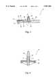
- FIG. 1is a top perspective view of one embodiment of the occluder of the present invention with the slider hidden behind the body;
- FIG. 2is a bottom perspective view of the occluder of the present invention
- FIG. 3is a side cross-sectional view of the occluder of the present invention in the occluding position
- FIG. 4is a cross-sectional view of the occluder of the present invention along line 4--4 in FIG. 3;
- FIG. 5is a side cross-sectional view of the occluder of the present invention in the open position
- FIG. 6is a cross-sectional view of the occluder of the present invention along line 6--6 in FIG. 5;
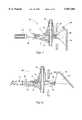
- FIG. 7is a cross-sectional view of an alternative embodiment of the occluder of the present invention in the open position, interacting with an associated medical device;
- FIG. 8is a cross-sectional view of the occluder in FIG. 7 in the occluding position, interacting with an associated medical device.
- FIGS. 1 and 2A preferred embodiment of occluder 10 of the present invention is shown in FIGS. 1 and 2.
- Occluder 10has a body member 12 and a slider member 14.
- Body member 12defines guides 16 and 18 which provide for engagement of body member 12 with slider member 14.
- Guides 16 and 18permit slider member 14 to slide relative to body member 12, wherein body member 12 extends over slider member's full range of motion relative to body member 12. Slider 14 is therefore fully encompassed by body 12, regardless of the slider's position and does not extend beyond the periphery of the body member.
- Occluder 10preferably provides external fitment 20 and internal fitment 22, wherein internal fitment 22 extends from body member 12 and external fitment 20 further extends from internal fitment 22.
- Fitments 20 and 22locate and bond segments of tube 40 to occluder 10 (as shown in FIGS. 4 and 6).
- Internal fitment 22further guides tube 40 through slider member 14.
- inner diameter of internal fitment 22is slightly larger than outer diameter of tube 40 to allow for slight shifting of tube 40 with the sliding movement of slider member 14 relative to body member 12.
- body member 12defines first stops 26 to arrest the sliding motion of slider member 14 in one direction, and second stops 27 to arrest the sliding motion of slider member 14 in the other direction.
- bump 17 on body 12 and ridge 19 on slider 14cooperate in the open position to provide tactile response, such as a snap, when the occluder is fully open.
- Body member 12further may define thumb or finger pad 24 above first stop 26, which in conjunction with first stop 26, increases ease of manual actuation of slider member 14 and makes loading of occluder 10 into a device more intuitive and user friendly.
- Grip 38 of slider member 14additionally increases ease of manual actuation of slider member 14 and can assist in loading and removing the occluder in and out of the associated medical device.
- first stop 26increases the difficulty of unintentional or accidental actuation of slider member 14 by partially shielding grip 38.
- first end 28 of body member 12is made of an opaque material and second end 30 of body member 12 is made of a clear material.
- first end 28 of body member 12is made of an opaque material and second end 30 of body member 12 is made of a clear material.
- slider member 14is situated at clear end 30 of body member 12 such that slider member 14 can be visible from a distance.
- slider member 14is in the open position (as shown in FIGS. 5 and 6)
- slider member 14is situated at opaque end 28 of body member 12 such that slider member 14 is not visible from a distance.
- slider member 14defines slot 32 through which tube 40 (shown in FIGS. 4 and 6) is located.
- Slot 32has an enlarged portion 34 and a narrower occluding portion 36.
- occluding portion 36 of slot 32is located adjacent to internal fitment 22, thereby situating tube 40 through occluding portion 36.
- the tubeis omitted from FIGS. 3 and 5 for greater clarity.
- the size of occluding portion 36 of slot 32is a predetermined amount smaller than that of tube 40, the interior surface of occluding portion 36 of slot 32 compresses and occludes tube 40, thereby preventing flow through tube 40.
- enlarged portion 34 of slot 32is located adjacent to internal fitment 22, thereby situating tube 40 through enlarged portion 34. Because the size of enlarged portion 34 of slot 32 is approximately the same or larger than that of tube 40, tube 40 is not compressed and thus fluid can flow through tube 40.
- FIGS. 3 and 4show occluder 10 in the occluding position, wherein slider member 14 is at the clear end 30 of body member 12, as previously described.
- tube 40is located through occluding portion 36 of slot 32 and is compressed by inner surface of occluding portion 36, thereby occluding passage of fluid through tube 40.
- FIGS. 5 and 6show occluder 10 in the open position, wherein slider member 14 is preferably at the opaque second side 30 of body member 12, as previously described.
- tube 40is located through enlarged portion 34 of slot 32 and is not compressed.
- slot 32is not occluding, but rather, is allowing passage of fluid through tube 40.
- slider member 14is moved along guides 16 and 18, either manually or automatically in cooperation with structure of an infusion pump device, from first end 28 to second end 30 of body member 12. This movement of slider member 14 causes tube 40 to shift from enlarged portion 34 to occluding portion 36 of slot 32.
- inner surface of occluding portion 36compresses tube 40, as previously described.
- fitments 20 and 22prevent tube 40 from slipping away from body member 12 despite the shifting of tube 40 along slot 32 of slider member 14.
- occluder 10allows for two stable positions, occluding (shown in FIGS. 3 and 4), and open (shown in FIGS. 5 and 6). Because body member 12 extends the full range of motion of slider member 14, body member 12 protects slider member 14 from unintended actuation when slider member 14 is in either the open or occluding position.
- FIG. 7 and 8show occluder 10A, an alternative embodiment of the present invention, interfacing with an associated medical device.
- FIG. 7shows occluder 10A in the open position while FIG. 8 shows occluder 10A in the occluding position.
- plunger 120driven by spring 122, contacts one end of slider member 14 and biases it to the occluding position.
- the doorcan be opened and closed via latch 106 which has actuating member 108 positioned to engage one end of slider member 14, opposite the end of the member against which spring driven plunger 120 is biased.
- actuating member 108engages one end of slider member 14, overrides the force of spring 122, and moves slider member 14 from the occluding position to the open position.
- actuating member 108fully engages slider member 14 such that slider member 14 is in the open position allowing for free flow of fluid through tube 40.
- body member 12may define slot 44 to accommodate actuating member 108 as the door closes such that actuating member 108 at least partially occupies slot 44 as it pushes on slider member 14 against the forces of the spring driven plunger.
- occluder 10Aprevents inadvertent free flow of fluid through tube 40.
- the spring driven plungerno mechanism on the door is necessary to pull slider member 14 from the open position into the occluding position, thereby eliminating the problems of accurately positioning any such pulling mechanism on the door.
- housing 110may define downwardly-sloping ramp 112.
- Slider member 14A of occluder 10Amay define support member 46, which, in conjunction with ramp 112, supports occluder 10A in the vertical axis when slider member 14A is in the open position, i.e. when support member 46 is in contact with ramp 112, thereby preventing excessive downward vertical motion of occluder 10A.
- Body member 12Amay also define open area 48 (better shown in FIGS. 1 and 2 for a similar embodiment) to accommodate the spring driven plunger such that the plunger engages grip 38 of the slider member and exerts spring forces thereon.
- the body membermay further define retaining member 50 such that a portion of housing 110 is situated between internal fitment 22 and retaining member 50 as shown in FIG. 7.
- the body memberis retained in housing 110 as the forcer of spring 122 urges retaining member 50 against portion of housing 100.
- the body memberis shaped to cooperate with the housing to ensure that it is properly loaded and seated in the housing when the door is closed.
Landscapes
- Health & Medical Sciences (AREA)
- Heart & Thoracic Surgery (AREA)
- Pulmonology (AREA)
- Engineering & Computer Science (AREA)
- Anesthesiology (AREA)
- Biomedical Technology (AREA)
- Hematology (AREA)
- Life Sciences & Earth Sciences (AREA)
- Animal Behavior & Ethology (AREA)
- General Health & Medical Sciences (AREA)
- Public Health (AREA)
- Veterinary Medicine (AREA)
- Infusion, Injection, And Reservoir Apparatuses (AREA)
Abstract
Description
Claims (19)
Priority Applications (1)
| Application Number | Priority Date | Filing Date | Title |
|---|---|---|---|
| US08/576,188US5967484A (en) | 1995-12-21 | 1995-12-21 | Intravenous tube occluder |
Applications Claiming Priority (1)
| Application Number | Priority Date | Filing Date | Title |
|---|---|---|---|
| US08/576,188US5967484A (en) | 1995-12-21 | 1995-12-21 | Intravenous tube occluder |
Publications (1)
| Publication Number | Publication Date |
|---|---|
| US5967484Atrue US5967484A (en) | 1999-10-19 |
Family
ID=24303334
Family Applications (1)
| Application Number | Title | Priority Date | Filing Date |
|---|---|---|---|
| US08/576,188Expired - LifetimeUS5967484A (en) | 1995-12-21 | 1995-12-21 | Intravenous tube occluder |
Country Status (1)
| Country | Link |
|---|---|
| US (1) | US5967484A (en) |
Cited By (22)
| Publication number | Priority date | Publication date | Assignee | Title |
|---|---|---|---|---|
| US6840492B1 (en) | 2003-11-21 | 2005-01-11 | Alaris Medical Systems, Inc. | Slide clamp |
| US20050256388A1 (en)* | 2002-06-17 | 2005-11-17 | Susi Roger E | Non-magnetic medical infusion device |
| US6985870B2 (en) | 2002-01-11 | 2006-01-10 | Baxter International Inc. | Medication delivery system |
| US20060011873A1 (en)* | 2004-07-16 | 2006-01-19 | Clarke Christopher J | Automatic clamp apparatus for IV infusion sets used in pump devices |
| US20060079758A1 (en)* | 2004-10-12 | 2006-04-13 | Susi Roger E | Non-magnetic medical infusion device |
| US20060129110A1 (en)* | 2004-07-16 | 2006-06-15 | Cardinal Health U.K. 305, Limited | Automatic clamp apparatus having lateral motion resistance for IV infusion sets |
| WO2007058951A3 (en)* | 2005-11-10 | 2007-08-23 | Iradimed Corp | Peristaltic liquid infusion apparatus |
| USD556904S1 (en) | 2004-07-16 | 2007-12-04 | Cardinal Health 303, Inc. | Automatic clamp device with offset release tab |
| WO2008102808A1 (en)* | 2007-02-21 | 2008-08-28 | Kobayashi Pharmaceutical Co., Ltd. | Valve device for urine collection bag and urine collection bag |
| JP2008229312A (en)* | 2007-02-21 | 2008-10-02 | Kobayashi Pharmaceut Co Ltd | Valve device for urine sampling bag and urine sampling bag |
| US20090076461A1 (en)* | 2007-07-13 | 2009-03-19 | Iradimed Corporation | System and method for communication with an infusion device |
| US7520489B2 (en) | 2003-06-17 | 2009-04-21 | Filtertek Inc. | Fluid handling device and method of making same |
| US20090254034A1 (en)* | 2008-04-01 | 2009-10-08 | Kent Beck | Safety occluder and method of use |
| USD635255S1 (en)* | 2010-08-06 | 2011-03-29 | WalkMed Infusion LLC | Combination slide clamp and occlusion clamp actuator |
| US8062008B2 (en) | 2007-09-27 | 2011-11-22 | Curlin Medical Inc. | Peristaltic pump and removable cassette therefor |
| WO2013078134A2 (en) | 2011-11-23 | 2013-05-30 | Carefusion 303, Inc. | Flexible tubing clamp and method |
| US8469933B2 (en) | 2011-03-18 | 2013-06-25 | Zyno Medical Llc | Pump activated pinch clamp |
| WO2016109968A1 (en)* | 2015-01-09 | 2016-07-14 | 福建省百仕韦医用高分子股份有限公司 | Clamping sleeve-type flow-stopping device |
| US9518667B2 (en) | 2012-08-30 | 2016-12-13 | C. R. Bard, Inc. | Tubing clamp |
| US9731105B2 (en) | 2015-02-20 | 2017-08-15 | Carefusion 303, Inc. | Micro infusion device for drug delivery |
| US20190298897A1 (en)* | 2018-03-28 | 2019-10-03 | Karl Storz Se & Co. Kg | Medical Instrument |
| US11268506B2 (en) | 2017-12-22 | 2022-03-08 | Iradimed Corporation | Fluid pumps for use in MRI environment |
Citations (23)
| Publication number | Priority date | Publication date | Assignee | Title |
|---|---|---|---|---|
| US207469A (en)* | 1878-08-27 | Improvement in hose-clamps | ||
| US1344433A (en)* | 1919-04-10 | 1920-06-22 | Emery D Blackburn | Hose-clamp |
| US2889848A (en)* | 1955-12-22 | 1959-06-09 | Redmer Sons Company | Flow control clamp |
| US3189038A (en)* | 1962-06-08 | 1965-06-15 | Baxter Don Inc | Variable flow clamp for flexible tubing |
| US3926175A (en)* | 1974-06-03 | 1975-12-16 | James H Allen | Implantable valve for medical purposes |
| US4247076A (en)* | 1979-04-16 | 1981-01-27 | Abbott Laboratories | Toggle action tubing clamp |
| US4439179A (en)* | 1982-02-16 | 1984-03-27 | Baxter Travenol Laboratories, Inc. | Dual tubing clamp |
| US4460358A (en)* | 1980-11-07 | 1984-07-17 | Ivac Corporation | Combined load and latch mechanism for fluid flow control apparatus |
| US4586691A (en)* | 1985-05-13 | 1986-05-06 | Warner-Lambert Company | Safety slide clamp |
| US4610664A (en)* | 1983-03-03 | 1986-09-09 | Anton Harle | Operation aspirator with control valve |
| US4689043A (en)* | 1986-03-19 | 1987-08-25 | Imed Corporation | IV tube activator |
| US4728324A (en)* | 1986-10-15 | 1988-03-01 | The Kendall Company | Urine meter valve with tamper indicator |
| US4818190A (en)* | 1987-12-01 | 1989-04-04 | Pacesetter Infusion, Ltd. | Cassette loading and latching apparatus for a medication infusion system |
| US4857048A (en)* | 1987-05-29 | 1989-08-15 | Hewlett-Packard Company | IV pump and disposable flow chamber with flow control |
| US4925152A (en)* | 1988-01-21 | 1990-05-15 | Hueber Karl Alexander | Air trap for shutting off flexible plastic tubing |
| US4932629A (en)* | 1989-09-18 | 1990-06-12 | Nova Biomedical Corporation | Clamp for flexible tubing |
| EP0423978A2 (en)* | 1989-10-20 | 1991-04-24 | Minnesota Mining And Manufacturing Company | Free flow prevention system for infusion pump |
| EP0510881A2 (en)* | 1991-04-23 | 1992-10-28 | Minnesota Mining And Manufacturing Company | Free flow prevention system for infusion pump |
| US5190527A (en)* | 1989-09-25 | 1993-03-02 | Baxter International Inc. | Intravenous metering device |
| WO1993005829A1 (en)* | 1991-09-26 | 1993-04-01 | Baxter International Inc. | Intravenous tube safety apparatus |
| US5238218A (en)* | 1992-07-15 | 1993-08-24 | Mackal Glenn H | Tube clamp |
| US5423769A (en)* | 1993-02-09 | 1995-06-13 | Dlp, Inc. | Cardioplegia management system |
| US5453098A (en)* | 1994-05-09 | 1995-09-26 | Imed Corporation | Two step IV fluid flow stop |
- 1995
- 1995-12-21USUS08/576,188patent/US5967484A/ennot_activeExpired - Lifetime
Patent Citations (24)
| Publication number | Priority date | Publication date | Assignee | Title |
|---|---|---|---|---|
| US207469A (en)* | 1878-08-27 | Improvement in hose-clamps | ||
| US1344433A (en)* | 1919-04-10 | 1920-06-22 | Emery D Blackburn | Hose-clamp |
| US2889848A (en)* | 1955-12-22 | 1959-06-09 | Redmer Sons Company | Flow control clamp |
| US3189038A (en)* | 1962-06-08 | 1965-06-15 | Baxter Don Inc | Variable flow clamp for flexible tubing |
| US3926175A (en)* | 1974-06-03 | 1975-12-16 | James H Allen | Implantable valve for medical purposes |
| US4247076A (en)* | 1979-04-16 | 1981-01-27 | Abbott Laboratories | Toggle action tubing clamp |
| US4460358A (en)* | 1980-11-07 | 1984-07-17 | Ivac Corporation | Combined load and latch mechanism for fluid flow control apparatus |
| US4439179A (en)* | 1982-02-16 | 1984-03-27 | Baxter Travenol Laboratories, Inc. | Dual tubing clamp |
| US4610664A (en)* | 1983-03-03 | 1986-09-09 | Anton Harle | Operation aspirator with control valve |
| US4586691A (en)* | 1985-05-13 | 1986-05-06 | Warner-Lambert Company | Safety slide clamp |
| US4689043A (en)* | 1986-03-19 | 1987-08-25 | Imed Corporation | IV tube activator |
| US4728324A (en)* | 1986-10-15 | 1988-03-01 | The Kendall Company | Urine meter valve with tamper indicator |
| US4857048A (en)* | 1987-05-29 | 1989-08-15 | Hewlett-Packard Company | IV pump and disposable flow chamber with flow control |
| US4818190A (en)* | 1987-12-01 | 1989-04-04 | Pacesetter Infusion, Ltd. | Cassette loading and latching apparatus for a medication infusion system |
| US4925152A (en)* | 1988-01-21 | 1990-05-15 | Hueber Karl Alexander | Air trap for shutting off flexible plastic tubing |
| US4932629A (en)* | 1989-09-18 | 1990-06-12 | Nova Biomedical Corporation | Clamp for flexible tubing |
| US5190527A (en)* | 1989-09-25 | 1993-03-02 | Baxter International Inc. | Intravenous metering device |
| EP0423978A2 (en)* | 1989-10-20 | 1991-04-24 | Minnesota Mining And Manufacturing Company | Free flow prevention system for infusion pump |
| US5017192A (en)* | 1989-10-20 | 1991-05-21 | Minnesota Mining And Manufacturing Company | Free flow prevention system for infusion pump |
| EP0510881A2 (en)* | 1991-04-23 | 1992-10-28 | Minnesota Mining And Manufacturing Company | Free flow prevention system for infusion pump |
| WO1993005829A1 (en)* | 1991-09-26 | 1993-04-01 | Baxter International Inc. | Intravenous tube safety apparatus |
| US5238218A (en)* | 1992-07-15 | 1993-08-24 | Mackal Glenn H | Tube clamp |
| US5423769A (en)* | 1993-02-09 | 1995-06-13 | Dlp, Inc. | Cardioplegia management system |
| US5453098A (en)* | 1994-05-09 | 1995-09-26 | Imed Corporation | Two step IV fluid flow stop |
Cited By (59)
| Publication number | Priority date | Publication date | Assignee | Title |
|---|---|---|---|---|
| US6985870B2 (en) | 2002-01-11 | 2006-01-10 | Baxter International Inc. | Medication delivery system |
| US7668731B2 (en) | 2002-01-11 | 2010-02-23 | Baxter International Inc. | Medication delivery system |
| US7553295B2 (en) | 2002-06-17 | 2009-06-30 | Iradimed Corporation | Liquid infusion apparatus |
| US20080004567A1 (en)* | 2002-06-17 | 2008-01-03 | Iradimed Corporation | Non-magnetic medical infusion device |
| US8150493B2 (en) | 2002-06-17 | 2012-04-03 | Iradimed Corporation | Patient infusion and imaging system |
| US8690829B2 (en) | 2002-06-17 | 2014-04-08 | Iradimed Corporation | Non-magnetic medical infusion device |
| US20110009733A1 (en)* | 2002-06-17 | 2011-01-13 | Iradimed Corporation | Non-magnetic medical infusion device |
| US20050256388A1 (en)* | 2002-06-17 | 2005-11-17 | Susi Roger E | Non-magnetic medical infusion device |
| US7267661B2 (en) | 2002-06-17 | 2007-09-11 | Iradimed Corporation | Non-magnetic medical infusion device |
| US7753882B2 (en) | 2002-06-17 | 2010-07-13 | Iradimed Corporation | Non-magnetic medical infusion device |
| US8038123B2 (en) | 2003-06-17 | 2011-10-18 | Filtertek Inc. | Fluid handling device and method of making same |
| US7520489B2 (en) | 2003-06-17 | 2009-04-21 | Filtertek Inc. | Fluid handling device and method of making same |
| US6840492B1 (en) | 2003-11-21 | 2005-01-11 | Alaris Medical Systems, Inc. | Slide clamp |
| CN101035592B (en)* | 2004-07-16 | 2010-05-05 | 卡迪纳尔健康303公司 | Automatic clamp apparatus for IV infusion sets used in pump devices |
| US20070102657A1 (en)* | 2004-07-16 | 2007-05-10 | Clarke Christopher J | Automatic clamp apparatus for IV infusion sets used in pump devices |
| WO2006019519A1 (en)* | 2004-07-16 | 2006-02-23 | Cardinal Health 303, Inc. | Automatic clamp apparatus for iv infusion sets used in pump devices |
| US7419133B2 (en) | 2004-07-16 | 2008-09-02 | Cardinal Health 303, Inc. | Automatic clamp apparatus for IV infusion sets used in pump devices |
| US20060129110A1 (en)* | 2004-07-16 | 2006-06-15 | Cardinal Health U.K. 305, Limited | Automatic clamp apparatus having lateral motion resistance for IV infusion sets |
| US7124996B2 (en) | 2004-07-16 | 2006-10-24 | Cardinal Health 303, Inc. | Automatic clamp apparatus for IV infusion sets used in pump devices |
| USD556904S1 (en) | 2004-07-16 | 2007-12-04 | Cardinal Health 303, Inc. | Automatic clamp device with offset release tab |
| US20060011873A1 (en)* | 2004-07-16 | 2006-01-19 | Clarke Christopher J | Automatic clamp apparatus for IV infusion sets used in pump devices |
| US7303175B2 (en) | 2004-07-16 | 2007-12-04 | Cardinal Health 303, Inc. | Automatic clamp apparatus having lateral motion resistance for IV infusion sets |
| US7404809B2 (en) | 2004-10-12 | 2008-07-29 | Iradimed Corporation | Non-magnetic medical infusion device |
| US20060079758A1 (en)* | 2004-10-12 | 2006-04-13 | Susi Roger E | Non-magnetic medical infusion device |
| US8262642B2 (en) | 2004-10-12 | 2012-09-11 | Iradimed Corporation | IV fluid infusion assembly |
| US10821223B2 (en) | 2005-11-10 | 2020-11-03 | Iradimed Corporation | Liquid infusion apparatus |
| WO2007058951A3 (en)* | 2005-11-10 | 2007-08-23 | Iradimed Corp | Peristaltic liquid infusion apparatus |
| US11045600B2 (en) | 2005-11-10 | 2021-06-29 | Iradimed Corporation | Liquid infusion apparatus |
| US20090264857A1 (en)* | 2005-11-10 | 2009-10-22 | Iradimed Corporation | Liquid infusion apparatus |
| US9878089B2 (en) | 2005-11-10 | 2018-01-30 | Iradimed Corporation | Liquid infusion apparatus |
| US8469932B2 (en)* | 2005-11-10 | 2013-06-25 | Iradimed Corporation | Liquid infusion apparatus |
| JP2008229312A (en)* | 2007-02-21 | 2008-10-02 | Kobayashi Pharmaceut Co Ltd | Valve device for urine sampling bag and urine sampling bag |
| WO2008102808A1 (en)* | 2007-02-21 | 2008-08-28 | Kobayashi Pharmaceutical Co., Ltd. | Valve device for urine collection bag and urine collection bag |
| US20090076461A1 (en)* | 2007-07-13 | 2009-03-19 | Iradimed Corporation | System and method for communication with an infusion device |
| US11291767B2 (en) | 2007-07-13 | 2022-04-05 | Iradimed Corporation | System and method for communication with an infusion device |
| US8105282B2 (en) | 2007-07-13 | 2012-01-31 | Iradimed Corporation | System and method for communication with an infusion device |
| US8500694B2 (en) | 2007-07-13 | 2013-08-06 | Iradimed Corporation | System and method for communication with an infusion device |
| US12246165B2 (en) | 2007-07-13 | 2025-03-11 | Iradimed Corporation | System and method for communication with an infusion device |
| US9861743B2 (en) | 2007-07-13 | 2018-01-09 | Iradimed Corporation | System and method for communication with an infusion device |
| US10617821B2 (en) | 2007-07-13 | 2020-04-14 | Iradimed Corporation | System and method for communication with an infusion device |
| US12251534B2 (en) | 2007-07-13 | 2025-03-18 | Iradimed Corporation | System for communication with an infusion device |
| US8062008B2 (en) | 2007-09-27 | 2011-11-22 | Curlin Medical Inc. | Peristaltic pump and removable cassette therefor |
| US9017296B2 (en)* | 2008-04-01 | 2015-04-28 | Zevex, Inc. | Safety occluder and method of use |
| US20090254034A1 (en)* | 2008-04-01 | 2009-10-08 | Kent Beck | Safety occluder and method of use |
| USD635255S1 (en)* | 2010-08-06 | 2011-03-29 | WalkMed Infusion LLC | Combination slide clamp and occlusion clamp actuator |
| US8469933B2 (en) | 2011-03-18 | 2013-06-25 | Zyno Medical Llc | Pump activated pinch clamp |
| EP2782634A4 (en)* | 2011-11-23 | 2015-08-19 | Carefusion 303 Inc | PIPE FOR FLEXIBLE TUBE AND METHOD |
| US9555232B2 (en) | 2011-11-23 | 2017-01-31 | Carefusion 303, Inc. | Positive bolus clamp |
| US10124158B2 (en) | 2011-11-23 | 2018-11-13 | Carefusion 303, Inc. | Positive bolus clamp |
| WO2013078134A2 (en) | 2011-11-23 | 2013-05-30 | Carefusion 303, Inc. | Flexible tubing clamp and method |
| US10155105B2 (en) | 2012-08-30 | 2018-12-18 | C. R. Bard, Inc. | Tubing clamp |
| US9518667B2 (en) | 2012-08-30 | 2016-12-13 | C. R. Bard, Inc. | Tubing clamp |
| WO2016109968A1 (en)* | 2015-01-09 | 2016-07-14 | 福建省百仕韦医用高分子股份有限公司 | Clamping sleeve-type flow-stopping device |
| US10322273B2 (en) | 2015-02-20 | 2019-06-18 | Carefusion 303, Inc. | Micro infusion device for drug delivery |
| EP3738625A1 (en) | 2015-02-20 | 2020-11-18 | CareFusion 303, Inc. | Y site comprising fluid obstruction mechanism for drug delivery |
| US9731105B2 (en) | 2015-02-20 | 2017-08-15 | Carefusion 303, Inc. | Micro infusion device for drug delivery |
| US11268506B2 (en) | 2017-12-22 | 2022-03-08 | Iradimed Corporation | Fluid pumps for use in MRI environment |
| US20190298897A1 (en)* | 2018-03-28 | 2019-10-03 | Karl Storz Se & Co. Kg | Medical Instrument |
| US11173241B2 (en)* | 2018-03-28 | 2021-11-16 | Karl Storz Se & Co. Kg | Medical instrument |
Similar Documents
| Publication | Publication Date | Title |
|---|---|---|
| US5967484A (en) | Intravenous tube occluder | |
| KR101676883B1 (en) | Safety occluder and method of use | |
| EP0900106B1 (en) | Pinch clip occluder for infusion sets | |
| CN101035592B (en) | Automatic clamp apparatus for IV infusion sets used in pump devices | |
| EP0569030B1 (en) | Flow control valve | |
| DK2298388T3 (en) | DEVICE AND PROCEDURE FOR PREVENTING FREE FLOW IN AN INFUSION HOSE | |
| EP1278566B1 (en) | Drip chamber anti free flow device | |
| CA2629449C (en) | Automatic clamp apparatus | |
| US7976513B2 (en) | Apparatus and method for selectively controlling flow in an infusion line | |
| EP0927061B1 (en) | Valve apparatus for use with an iv set | |
| US5865813A (en) | Intravenous tube occluder | |
| AU2001253883A1 (en) | Drip chamber anti free flow device | |
| US20070265559A1 (en) | Transfusion Safety Device | |
| HK1110537B (en) | Automatic clamp apparatus for iv infusion sets used in pump devices |
Legal Events
| Date | Code | Title | Description |
|---|---|---|---|
| AS | Assignment | Owner name:BANKERS TRUST COMPANY, NEW YORK Free format text:SECURITY INTEREST;ASSIGNOR:IVAC HOLDINGS, INC.;REEL/FRAME:008568/0540 Effective date:19961126 | |
| AS | Assignment | Owner name:ALARIS MEDICAL SYSTEMS, INC., CALIFORNIA Free format text:CHANGE OF NAME;ASSIGNOR:IVAC HOLDINGS, INC.;REEL/FRAME:008988/0431 Effective date:19970425 Owner name:IVAC HOLDINGS, INC., CALIFORNIA Free format text:MERGER;ASSIGNOR:IMED CORPORATION;REEL/FRAME:008989/0080 Effective date:19961126 | |
| STCF | Information on status: patent grant | Free format text:PATENTED CASE | |
| AS | Assignment | Owner name:IISBC BANK USA, NEW YORK Free format text:SECURITY INTEREST;ASSIGNOR:ALARIS MEDICAL SYSTEMS, INC.;REEL/FRAME:013403/0338 Effective date:20011016 | |
| FPAY | Fee payment | Year of fee payment:4 | |
| AS | Assignment | Owner name:ALARIS MEDICAL SYSTEMS, INC., CALIFORNIA Free format text:CHANGE OF NAME;ASSIGNOR:ALARIS MEDICAL, INC.;REEL/FRAME:014201/0592 Effective date:20030630 Owner name:ALARIS MEDICAL SYSTEMS, INC., CALIFORNIA Free format text:SECURITY AGREEMENT;ASSIGNOR:HSBC BANK USA;REEL/FRAME:014220/0171 Effective date:20030630 Owner name:ALARIS MEDICAL, INC., CALIFORNIA Free format text:MERGER;ASSIGNOR:ALARIS MEDICAL SYSTEMS, INC.;REEL/FRAME:014220/0417 Effective date:20030630 Owner name:CITICORP NORTH AMERICA, INC., NEW YORK Free format text:SECURITY AGREEMENT;ASSIGNOR:ALARIS MEDICAL SYSTEMS, INC.;REEL/FRAME:014220/0315 Effective date:20030630 | |
| AS | Assignment | Owner name:ALARIS MEDICAL SYSTEMS, INC., CALIFORNIA Free format text:RELEASE OF SECURITY AGREEMENT;ASSIGNOR:CITICORP NORTH AMERICA, INC.;REEL/FRAME:015703/0127 Effective date:20040707 | |
| AS | Assignment | Owner name:CARDINAL HEALTH 303, INC., CALIFORNIA Free format text:CHANGE OF NAME;ASSIGNOR:ALARIS MEDICAL SYSTEMS, INC.;REEL/FRAME:017006/0905 Effective date:20041013 | |
| FPAY | Fee payment | Year of fee payment:8 | |
| AS | Assignment | Owner name:CAREFUSION 303, INC.,CALIFORNIA Free format text:CHANGE OF NAME;ASSIGNOR:CARDINAL HEALTH 303, INC.;REEL/FRAME:023800/0598 Effective date:20090801 Owner name:CAREFUSION 303, INC., CALIFORNIA Free format text:CHANGE OF NAME;ASSIGNOR:CARDINAL HEALTH 303, INC.;REEL/FRAME:023800/0598 Effective date:20090801 | |
| FPAY | Fee payment | Year of fee payment:12 |