US5966027A - Symmetric logic block input/output scheme - Google Patents
Symmetric logic block input/output schemeDownload PDFInfo
- Publication number
- US5966027A US5966027AUS08/940,437US94043797AUS5966027AUS 5966027 AUS5966027 AUS 5966027AUS 94043797 AUS94043797 AUS 94043797AUS 5966027 AUS5966027 AUS 5966027A
- Authority
- US
- United States
- Prior art keywords
- cluster
- logic
- programmable
- matrix
- logic device
- Prior art date
- Legal status (The legal status is an assumption and is not a legal conclusion. Google has not performed a legal analysis and makes no representation as to the accuracy of the status listed.)
- Expired - Lifetime
Links
Images


Classifications
- H—ELECTRICITY
- H03—ELECTRONIC CIRCUITRY
- H03K—PULSE TECHNIQUE
- H03K19/00—Logic circuits, i.e. having at least two inputs acting on one output; Inverting circuits
- H03K19/02—Logic circuits, i.e. having at least two inputs acting on one output; Inverting circuits using specified components
- H03K19/173—Logic circuits, i.e. having at least two inputs acting on one output; Inverting circuits using specified components using elementary logic circuits as components
- H03K19/177—Logic circuits, i.e. having at least two inputs acting on one output; Inverting circuits using specified components using elementary logic circuits as components arranged in matrix form
- H03K19/17736—Structural details of routing resources
- H—ELECTRICITY
- H03—ELECTRONIC CIRCUITRY
- H03K—PULSE TECHNIQUE
- H03K19/00—Logic circuits, i.e. having at least two inputs acting on one output; Inverting circuits
- H03K19/02—Logic circuits, i.e. having at least two inputs acting on one output; Inverting circuits using specified components
- H03K19/173—Logic circuits, i.e. having at least two inputs acting on one output; Inverting circuits using specified components using elementary logic circuits as components
- H03K19/177—Logic circuits, i.e. having at least two inputs acting on one output; Inverting circuits using specified components using elementary logic circuits as components arranged in matrix form
- H03K19/17724—Structural details of logic blocks
- H03K19/17728—Reconfigurable logic blocks, e.g. lookup tables
- H—ELECTRICITY
- H03—ELECTRONIC CIRCUITRY
- H03K—PULSE TECHNIQUE
- H03K19/00—Logic circuits, i.e. having at least two inputs acting on one output; Inverting circuits
- H03K19/02—Logic circuits, i.e. having at least two inputs acting on one output; Inverting circuits using specified components
- H03K19/173—Logic circuits, i.e. having at least two inputs acting on one output; Inverting circuits using specified components using elementary logic circuits as components
- H03K19/177—Logic circuits, i.e. having at least two inputs acting on one output; Inverting circuits using specified components using elementary logic circuits as components arranged in matrix form
- H03K19/17736—Structural details of routing resources
- H03K19/17744—Structural details of routing resources for input/output signals
Definitions
- the present inventionrelates to programmable logic devices and, more particularly, to signal routing schemes within such devices.
- PLDProgrammable Logic Devices
- PLAProgrammable Logic Arrays
- PALTMProgrammable Array Logic
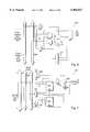
- FIG. 1shows a conventional Complex Programmable Logic Device (“CPLD") 100 which includes a Programmable Interconnect Matrix (“PIM”) 110 and eight logic blocks 120. Other CPLDs may include different numbers of logic blocks. As shown, CPLD 100 has a total of 262 inputs, each of which is connected to the PIM 110. The PIM 110 is capable of providing each logic block 120 with its own set of input terms by independently selecting as many as 36 of the possible 262 input signals as input terms for each logic block 120. The compliments for each of the 36 signals output by the PIM 110 are also provided to each logic block 120. Thus, each logic block receives as many as 72 input terms from the PIM 110.
- CPLD 100has a total of 262 inputs, each of which is connected to the PIM 110.
- the PIM 110is capable of providing each logic block 120 with its own set of input terms by independently selecting as many as 36 of the possible 262 input signals as input terms for each logic block 120. The compliments for each of the 36 signals output by the PIM 110 are also
- the PIM 110includes a number of programmable elements (not shown) for controlling an array of multiplexers (not shown) to reduce the total number of programmable elements required.
- the programmable elementsmay be volatile memory elements such as static random access memory (“SRAM”), non-volatile memory elements such as flash electrically easrable programmable read only memory (“Flash EEPROM”), or fuses.
- the programmable elements of the PIM 110may be implemented to control a matrix of cross point switches; however, this increases the total number of programmable elements required to make the same number of connections.
- each output conductorcan be connected to at least one input conductor.
- both forms of connectionsperform a multiplexing function in the sense of both forms of connection provide for the selection of one of the input conductors from the set of many input conductors.
- the 262 inputs to the PIM 110include 128 feedback signals, 128 input signals and 6 dedicated input signals which include 4 clock signals. Sixteen feedback signals and as many as 16 input signals are provided by each logic block 120. Each logic block 120 is programmed to perform selected logic functions using sub-combinations of the 72 input terms provided by the PIM 110. Each logic block 120 has 16 input/output (“I/O") pins 125, which may be used as either inputs to the PIM 110 or outputs of the CPLD 100.
- I/Oinput/output
- the CPLD 100may be regarded as a PIM coupled in series with 8 PLDs coupled in parallel, where each individual logic block 120 corresponds to a single PLD. Intermediate stages in the outputs of each of the 8 PLDs are fed back as inputs to the PIM. Depending on the particular set of input signals routed to the outputs of the PIM and the programmed logic functions for each logic block 120, the 8 PLDs may, in fact, act as two or more PLDs coupled in series with each other. CPLD 100 thus provide a highly versatile logic device.
- FIG. 2shown portions of CPLD 100 in greater detail.
- a logic block 120is shown as including a product term array 210, a product term allocator 215, macrocells 220 and I/O cells 225.
- the product term array 210may be a fully programmable AND array and the product term allocator 215 is configured to allocate product terms from the product term array 210 to 16 macrocells 220.
- the product term allocator 215"steers" product terms to macrocells 220 as needed. For example, if one macrocell requires ten products terms while another requires only three product terms, the product term allocator 215 steers ten product terms to one macrocell and three product terms to the other macrocell. Depending on the configuration, up to 16 product terms can be steered to any one macrocell.
- the output for each of the 16 macrocells 220are fed back to the PIM 110 as input signals.
- the specific architecture of the macrocells 220may be any appropriate architecture and each macrocell 220 may include registers and/or buffers.
- the 16 outputs of the macrocells 220are also fed to 16 I/O cells 225.
- Each of the 16 I/O cells 225can be programmed to provide output signals to an I/O pin 125 or input signals to the PIM 110.
- CPLD 100provides a highly versatile programmable logic device.
- FIGS. 1 and 2provide a highly versatile programmable logic device.
- CPLD 300consists of logic blocks connected by two levels of interconnect. Each group of four logic blocks 310 is given its own routing resource, called a Block Interconnect 320. Together, the four logic blocks 310 and their block interconnect 320 are called a segment 330.
- the second level of interconnect, segment interconnect 340ties all of the segments 330 together. Segment interconnect 340 also provides a routing path for a number of global clock signals 350.
- Each logic block 310consists of macrocells, logic arrays, logic allocators, I/O cells and any necessary control signal generators. Thus, each logic block 310 resembles an independent PLD device.
- I/O cells associated with each logic block 310may have signal paths which feed directly back to that logic block (local feedback paths) which may be used to route signals from the I/O cell back to the logic block.
- an interconnect feedermay assign a block interconnect line to that signal. The interconnect feeder may act as an input switch matrix.
- the block interconnect 320 and segment interconnect 340provide connections between any two signals in CPLD 300.
- Block interconnect lines and local feedback linesare assigned as required.
- segment interconnect 340 and block interconnect 320are each multiplexer-based interconnect structures. As such, segment interconnect 340 and block interconnects 320 require significant die area, thus leading to increased fabrication costs for CPLD 300. Segment interconnect 340 is required to be multiplexer-based because of the need to provide interconnection between every logic block 310 of CPLD 300. Although such a scheme may provide maximum connectability, it tends to ignore "real-world" designs which typically implement related logic functions in related logic blocks of a segment, thus avoiding the need to transmit numerous signals across an interconnect between segments.
- a programmable logic deviceincluding a plurality of clusters of logic blocks.
- Each of the clustersmay include a respective programmable interconnect matrix with each of the logic blocks of each cluster being coupled to the respective programmable interconnect matrix of the cluster.
- Each of the clustersmay be symmetrically coupled to a row and a column of a global routing matrix.
- the row and the column of the global routing matrixmay be symmetrical and each row and/or column may be coupled to an input/output cell of the programmable logic device.
- the global routing matrixmay comprise a plurality of programmable interconnections.
- a symmetrical input/output scheme for a programmable logic devicemay include a first level routing architecture configured to provide limited intercommunication between a first cluster of logic blocks and a second cluster of logic blocks and a second level routing architecture configured to provide intercommunication between logic blocks within the first cluster.
- the second level routing architecturebeing symmetrically coupled to the first level routing architecture at two points of the first cluster.
- the symmetrical input/output schememay have the second level routing architecture coupled to the first level routing architecture through a programmable interconnect matrix.
- the first level routing architecturemay further comprise a non-segmented routing matrix which may be symmetrical and which may be laid out as a row and column routing matrix.
- FIG. 1illustrates a conventional complex programmable logic device layout
- FIG. 2illustrates a conventional complex programmable logic device signal path
- FIG. 3illustrates a high density complex programmable logic device employing block and segment, multiplexer-based interconnect structures
- FIG. 4illustrates a high density complex programmable logic device having a scalable routing architecture according to one embodiment of the present invention
- FIG. 5illustrates an exemplary logic block for the complex programmable logic device of FIG. 4
- FIG. 6illustrates an exemplary macrocell for the complex programmable logic device of FIG. 4
- FIG. 7illustrates an exemplary I/O block for the complex programmable logic device of FIG. 4;
- FIG. 8illustrates an exemplary I/O block-to-channel connection for the complex programmable logic device of FIG. 4, according to one embodiment of the present invention
- FIG. 9aillustrates an exemplary cluster-to-channel connection for the complex programmable logic device of FIG. 4, according to one embodiment of the present invention
- FIG. 9billustrates a channel-to-cluster input in greater detail
- FIG. 9cillustrates a channel-two channel connection for the complex programmable logic device of FIG. 4, according to one embodiment of the present invention.
- FIGS. 10a, 10b and 10cillustrates conventional cluster-to-channel connection schemes
- FIG. 11illustrates a symmetrical interconnection scheme for logic elements of a programmable logic device.
- Described hereinis a symmetrical input/output connection scheme for clusters of logic blocks of a high density complex programmable logic device.
- the present inventionallows signals travelling to/from a global channel routing architecture to enter/exit a cluster through two separate points of the logic cluster. One point may be connected to an adjacent row of the channel and another to an adjacent column of the channel.
- the novel routing architectureinvolves the utilization of a two-dimensional network of non-segmented routing tracks or channels to serve as global interconnects between clusters of logic blocks.
- Each cluster of logic blocksis a CPLD-like structure which includes a number of logic blocks connected together by a local interconnect.
- Logic signals that need to enter a cluster, either from an I/O pin or from another logic block, of another clusterdo so by traversing from those sources though a channel interconnect.
- logic signals produced by a clustercan be routed to an I/O pin or to another logic block of another cluster across one of the channels.
- a switch matrixis implemented at intersections between the channels to allow logic signals to be transferred between rows and columns of the channels.
- FIG. 4shows a high density complex programmable logic device (CPLD) 400 incorporating these and other features of the present invention.
- CPLD 400may be implemented on a single semiconductor die.
- CPLD 400includes a plurality of clusters of logic blocks 410.
- Each cluster 410includes a programmable interconnect matrix (PIM) 420 and a number of logic blocks 430.
- PIMprogrammable interconnect matrix
- FIG. 4eight logic blocks 430 are shown for each cluster 410, it should be appreciated that a cluster 410 may include any number of logic blocks, preferably more than two, and in some cases four or more.
- each cluster 410may resemble a complex programmable logic device such as that illustrated in FIG. 1.
- CPLD 400is shown in FIG. 4 as including six clusters of logic blocks 410, it should be appreciated that any number of clusters 410 may be included, preferably more than two, and in some cases six or more or eight or more.
- Each PIM 420includes a number of programmable elements (not shown) for controlling an array of multiplexers (not shown) to reduce the total number of programmable elements required.
- the programmable elementsmay be volatile memory elements such as static random access memory (SRAM), nonvolatile memory elements such as flash electrically erasable programmable read only memory (“Flash EEPROM”), antifuses or fuses.
- the programmable elements of each PIM 420may be implemented to control a matrix of cross point switches.
- Each logic block 430may be programmed to perform selected logic functions using sub-combinations of the inputs provided by the PIM 420.
- each cluster 410may be regarded as a PIM coupled in series with a number of programmable logic devices coupled in parallel, wherein each logic block 430 corresponds to a single programmable logic device. Intermediate stages and the outputs of each of the programmable logic devices are fed back as inputs to the PIM 420.
- the individual programmable logic devicesmay, in fact, act as two or more programmable logic devices coupled in series with each other.
- Each cluster 410thus provides a highly versatile logic device in and of itself.
- Each cluster 410is also coupled to a second level routing architecture which includes channels 440 and 450.
- Channels 440 and 450make up a row and column (respectively), non-segmented routing matrix.
- Each channel 440 and 450may include the same number of non-segmented interconnects, thus making the row and column routing matrix symmetrical in nature.
- different numbers of individual interconnectsmay be included within each channel 440 or 450.
- each vertical channel 450may include from 182 to 208 individual interconnects while each horizontal channel 440 may include from 273 to 289 individual interconnects.
- the exact number of interconnects to be included in any channel 440 or 450is a design choice and will depend on the overall layout of CPLD 400. For example, different numbers of interconnects may be required to accomodate memory elements associated with one or more clusters. In general, however, the second level routing achritecture provides only for limited communication between clusters 410.
- Access to an individual cluster 410 from one of the channels 440 or 450is though a cluster's respective PIM 420.
- each PIM 420is configured to provide intercommunication between its plurality of the associated logic blocks and the second level routing architecture.
- Access from an individual cluster 410 to one of the channels 440 or 450is via a logic block 430.
- a switch matrixis implemented at every interconnection between a row and a column of the second level routing architecture. This allows logic signals to be transmitted from channel 450 to channels 440, or vice versa.
- This layout of the second level routing architectureallows for an example of signals between adjacent clusters 410 to be very rapid because such signals need not pass through both a row and column channel.
- the advantage of this hybrid routing architectureis that by choosing a cluster size (i.e., the number of logic blocks 430 per cluster 410) that will encompass a high percentage of logic signals, those signals that are local to a cluster 410 will be able to take advantage of the high routing flexibility of the multiplexer-based local PIM 420.
- a cluster sizei.e., the number of logic blocks 430 per cluster 410
- those signals that are local to a cluster 410will be able to take advantage of the high routing flexibility of the multiplexer-based local PIM 420.
- a low cost (in terms of silicon die area and delay) channel-based interconnect schemeis used for the few global signals that need to travel across cluster boundaries.
- schemes such as that shown in FIG. 3 that contain only CPLD-type, multiplexer-based interconnectsincur much higher silicon die area and delay costs for the same device density.
- the hybrid hierarchical routing architecture(i.e., one made up of a local interconnect per cluster and a cluster interconnect) provides an optimization for a high density programmable logic device 400.
- the present inventionprovides a programmable logic device which includes a number of clusters of logic blocks, each of the clusters having a respective programmable interconnect matrix.
- Each of the logic blocks of each clusterare coupled to the cluster's respective programmable interconnect matrix.
- Each of the clustersare coupled to other clusters though a row and column, non-segmented routing matrix.
- the row and column routing matrixmay be symmetrical and is made up of a number of programmable interconnections as described further below.
- each of the clustersmay be symmetrically coupled to a row and a column of the global routing matrix.
- This symmetrical input/output schememay be described as a first level routing architecture configured to provide limited intercommunication between a first cluster of logic blocks and a second cluster of logic blocks and a second level routing architecture configured to provide intercommunication between logic blocks within the first cluster.
- the second level routing architecturebeing symmetrically coupled to the first level routing architecture at two points of the first cluster.
- the symmetrical input/output schememay have the second level routing architecture coupled to the first level routing architecture through a programmable interconnect matrix.
- CPLD 400also includes a number of I/O blocks 460.
- the I/O blocks 460are coupled to the channels 440 and 450 and each includes a number of input/output pins which may be used as either inputs to a cluster 410 or outputs of the CPLD 400.
- FIG. 5shows the portions of a cluster 430 in greater detail.
- an exemplary logic block 500is shown as including a product term array 510, a product term allocator 515 and a number of macrocells 520. Signals from a local PIM 420 are routed to the product term array 510 which may be a fully programmable AND array.
- Product term allocator 515allocates product terms from the product term array 510 to the macrocells 520. For each logic block 500, 16 macrocells 520 may be included.
- Product term allocator 515steers product terms to the macrocells 520 as needed.
- the product term allocator 515steers ten product terms to the first macrocell and three product terms to the second macrocell. For one embodiment, up to 16 product terms can be steered to any one macrocell 520.
- the outputs for each of the macrocells 520are fed back to the PIM 420 as input signals.
- product termsmay be fed directly to the macrocells 520 from the product term array 510.
- global clock signals 525are provided on a global clock bus 530 to each of the macrocells 520.
- the global clock signals 525may be common to an entire cluster or to multiple clusters.
- Individual product term clock signals 535may be provided to the macrocells 520 from the product term array 510.
- FIG. 6illustrates an exemplary macrocell 600 in more detail.
- macrocell 600may include any appropriate architecture for implementing desired logic functions.
- a register 610may be provided and configured to receive inputs from product term allocator 515.
- Clock signalsmay be provided to operate register 610 from a global clock bus 530 and other timing signals, for example to reset register 610, may be provided from product term array 510.
- Various multiplexers and/or logic gates, as shown in FIG. 6,may be used to achieve desired logic and/or timing functions to produce output signals which are ultimately routed back to a local PIM 420.
- FIG. 7illustrates an exemplary I/O cell 700 for CPLD 400.
- the outputs of macrocellsmay be fed though routing channels 440 and/or 450 to an I/O cell 700.
- Each of the I/O cells 700may include various registers 710 and 720 as well as a three state output buffer 725 coupled to an I/O pin 730.
- Each I/O cell 700may be programmed to change the way the output buffer 725 is enabled and/or disabled. Inputs or outputs of the I/O cells 700 may be fed back to the routing channels 440 or 450 as desired.
- the use of various multiplexers 735allows for the control of the timing of register 710 or 720 to achieve desired input and/or output functions.
- a number of I/O cells 700make up an I/O block 800 which is coupled to a routing channel 440 or 450.
- Each I/O cell 700 within an I/O block 800is provided with an output to the routing channel 440 or 450 and each I/O cell 700 may receive inputs from the channels 440 or 450 from one or more of the clusters 410.
- Each output 810 for an I/O cell 700is a dedicated line or interconnect in one of the routing channels 440 or 450. These outputs 810 may be used to provide signals to any of the clusters 410. Similarly, any of the clusters 410 may provide signals to any of the I/O cells 700 of an I/O block 800 using signal paths 820 which are also part of routing channel 440 or 450. In FIG. 8, the interconnections illustrated in area 830 show that though the use of programmable interconnections, various signals 820 may be provided to I/O cells 700. These connections perform a multiplexing function in the sense that they provide for the selection of one input conductor from a set of many input conductors.
- the term "multiplexer” or the illustration of multiplexer in FIG. 8should be understood to encompass any circuit that performs a multiplexing function, regardless of the number of programmable elements required to control that circuit.
- the programmable elements and/or the multiplexing functionmay be implemented as volatile memory elements such as static random access memory.
- FIG. 9aillustrates the interconnection of cluster 410 to channels 440 and 450.
- the interconnection between these elements of CPLD 400may be provided through a local PIM 420 within cluster 410.
- channel 440is a row within the second level routing architecture.
- 64 bi-directional interconnectionsmay be provided to couple channel 440 to cluster 410.
- the interconnection of cluster 410 to channel 450(a column within the second level routing architecture) may be similar to that between cluster 410 and channel 440.
- cluster 410includes 64 dedicated outputs to channel 450, each output corresponding to an individual conductor within channel 450.
- up to 64 signals from cluster 410may be routed to channel 450.
- cluster 410may receive up to 64 inputs from channel 450. However, the inputs will generally be received from conductors in channel 450 other than those associated with the dedicated outputs of cluster 410. This is because there is no need to route signals outside of cluster 410 to be used as inputs to cluster 410 because local PIM 420 provides such interconnection for signals within cluster 410.
- the symmetrical interconnection of a cluster 410 to a row 440 and column 450 of the global interconnectis one example of a broader aspect of the present invention.
- the present inventionprovides a means for symmetrically interconnecting a logic element of a programmable logic device to a row and column of a global interconnect.
- FIG. 11shows a programmable logic device 1000 having a plurality of logic elements 1010, each having a symmetrical interconnection to a row 1020 and column 1030 of a global interconnect matrix 1040.
- the term symmetrical interconnectionmeans that signals may be passed to/from a logic element 1010 from/to a row 1020 and column 1030 of the global interconnect matrix 1040 with equal ease.
- the individual logic elements 1010may be clusters of logic blocks, individual logic blocks, pluralities of logic blocks (e.g., arranged in configurations other than a cluster), memory cells, blocks of memories (e.g., dual port memories, first-in-first-out memories, etc.), registers, gates, multiplexers or other elements of a programmable logic device or any combination thereof.
- the logic elementsmay be arranged in different configurations, such as a 4 ⁇ 4 matrix, 2 ⁇ 3 matrix, 20 ⁇ 20 matrix, etc.
- FIG. 9aillustrates an exemplary aspect of the present invention wherein a symmetrical interconnection is provided for a cluster 410 to channels 440 and 450.
- This aspect of the present inventionallows signals to be passed to or from a cluster to a vertical or horizontal channel with equal ease.
- such a schemealso allows for easier fabrication by providing uniformity at all cluster-to-channel interconnections.
- the symmetrical interconnection of a cluster 410 to channels 440 and 450also provides a departure from and an improvement over schemes of the past.
- signals from logic blockshave been restricted to enter or exit a cluster in one of three ways.
- FIG. 10aone scheme allows logic signals to enter a cluster from channels on one side and exit on the other side.
- FIG. 10bAnother scheme, illustrated in FIG. 10b, allows logic signals to enter a cluster from channels on only one side. In this scheme, signals can exit to channels on either side of the cluster but such signals compete with other signals in the channels that need to make a "turn" from a column to a row.
- schemes such as that shown in FIG. 10callow signals to enter/exit a cluster from/to a channel on only one side of the cluster. The present invention provides advantages over each of these schemes.
- the present inventionachieves reduced signal delay, increased routability and enhanced pin-locking capability.
- Improved signal delayis achieved because the present invention reduces potential delay for global signals. That is, signals may now enter or exit a cluster from alternate directions, avoiding the need to compete with other global signals in the channels, for example, signals can now be directed to a particular column or row, avoiding the need to pass through a channel switching box.
- Increased pin-locking capabilityis achieved as signals that are locked to either a column-or row-related I/O block 460 can enter a cluster 410 without having to go through a channel switch box.
- Increased global routabilityis achieved because signals that cannot enter/exit a cluster due to channel traffic congestion can still enter/exit through an alternate route.
- the 64 inputs to cluster 410 from channel 450are illustrated in FIG. 9a in a fashion similar to that shown for I/O block 800 in FIG. 8. That is, programmable elements may be used to provide routing between conductors within channel 450 and the inputs to cluster 410.
- conductors 910 within a channel 440 or 450may be provided as inputs to a multiplexing function 920 under the control of a programmable element 925.
- programmable element 925an individual signal from one of the conductors 910 may be provided to an individual cluster input 930.
- the programmable element 925may be a volatile memory element such as an SRAM, a non-volatile element such as a Flash EEPROM, a fuse or an antifuse. Alternatively, a matrix of cross point switches may be used.
- the multiplexing functionitself may be performed through the use of programmable elements, such as SRAM. Regardless of the individual structure, however, it is the multiplexing function which is performed, in the sense that there is a selection of one input conductor from a set of many inputs conductors, that is important.
- FIG. 9cshows the routing of signals between a row channel 440 and a column channel 450.
- Individual conductors 940 within channel 440 and 945 within channel 450may need to be connected. This may be accomplished through the use of a passgate or similar device 950 under the control of a programmable element.
- the programmable element which controls passgate 950may be a volatile memory element such as an SRAM, a non-volatile memory element such as a Flash EEPROM, a fuse or an antifuse.
- passgate 950provides an interconnection between conductors 940 and 945, thus enabling signals to be routed from channel 450 to channel 440 or vice verse. When the programmable element is not programmed, no such interconnection is provided.
- the programmable logic devicemay include a plurality of clusters, each having a respective programmable interconnect matrix. Each of the clusters may be symmetrically coupled to a row and a column of a global routing matrix. The row and the column of the global routing matrix may themselves be symmetrical and each row and/or column may be further coupled to an input/output cell of the programmable logic device.
Landscapes
- Physics & Mathematics (AREA)
- Mathematical Physics (AREA)
- Engineering & Computer Science (AREA)
- Computer Hardware Design (AREA)
- Computing Systems (AREA)
- General Engineering & Computer Science (AREA)
- Computer Networks & Wireless Communication (AREA)
- Logic Circuits (AREA)
- Design And Manufacture Of Integrated Circuits (AREA)
Abstract
Description
Claims (17)
Priority Applications (2)
| Application Number | Priority Date | Filing Date | Title |
|---|---|---|---|
| US08/940,437US5966027A (en) | 1997-09-30 | 1997-09-30 | Symmetric logic block input/output scheme |
| US09/357,716US6696855B1 (en) | 1997-09-30 | 1999-07-20 | Symmetric logic block input/output scheme |
Applications Claiming Priority (1)
| Application Number | Priority Date | Filing Date | Title |
|---|---|---|---|
| US08/940,437US5966027A (en) | 1997-09-30 | 1997-09-30 | Symmetric logic block input/output scheme |
Related Child Applications (1)
| Application Number | Title | Priority Date | Filing Date |
|---|---|---|---|
| US09/357,716ContinuationUS6696855B1 (en) | 1997-09-30 | 1999-07-20 | Symmetric logic block input/output scheme |
Publications (1)
| Publication Number | Publication Date |
|---|---|
| US5966027Atrue US5966027A (en) | 1999-10-12 |
Family
ID=25474839
Family Applications (2)
| Application Number | Title | Priority Date | Filing Date |
|---|---|---|---|
| US08/940,437Expired - LifetimeUS5966027A (en) | 1997-09-30 | 1997-09-30 | Symmetric logic block input/output scheme |
| US09/357,716Expired - LifetimeUS6696855B1 (en) | 1997-09-30 | 1999-07-20 | Symmetric logic block input/output scheme |
Family Applications After (1)
| Application Number | Title | Priority Date | Filing Date |
|---|---|---|---|
| US09/357,716Expired - LifetimeUS6696855B1 (en) | 1997-09-30 | 1999-07-20 | Symmetric logic block input/output scheme |
Country Status (1)
| Country | Link |
|---|---|
| US (2) | US5966027A (en) |
Cited By (65)
| Publication number | Priority date | Publication date | Assignee | Title |
|---|---|---|---|---|
| US6140839A (en)* | 1998-05-13 | 2000-10-31 | Kaviani; Alireza S. | Computational field programmable architecture |
| US6150841A (en)* | 1999-06-06 | 2000-11-21 | Lattice Semiconductor Corporation | Enhanced macrocell module for high density CPLD architectures |
| US6184713B1 (en) | 1999-06-06 | 2001-02-06 | Lattice Semiconductor Corporation | Scalable architecture for high density CPLDS having two-level hierarchy of routing resources |
| US6198305B1 (en)* | 1998-03-24 | 2001-03-06 | Cypress Semiconductor Corp. | Reduced area product-term array |
| US6201408B1 (en) | 1998-05-30 | 2001-03-13 | Cypress Semiconductor Corp. | Hybrid product term and look-up table-based programmable logic device with improved speed and area efficiency |
| US6211696B1 (en)* | 1998-05-30 | 2001-04-03 | Cypress Semiconductor Corp. | Hybrid product term and look-up table-based programmable logic device with improved speed and area efficiency |
| US6388464B1 (en) | 1999-12-30 | 2002-05-14 | Cypress Semiconductor Corp. | Configurable memory for programmable logic circuits |
| US6441642B1 (en)* | 2001-02-20 | 2002-08-27 | Cypress Semiconductor Corp. | Multiplexers for efficient PLD logic blocks |
| US6466051B1 (en) | 2001-02-20 | 2002-10-15 | Cypress Semiconductor Corp. | Multiplexers for efficient PLD logic blocks |
| US6531889B1 (en)* | 2000-10-10 | 2003-03-11 | Altera Corporation | Data processing system with improved latency and associated methods |
| US6545505B1 (en)* | 1997-09-30 | 2003-04-08 | Cypress Semiconductor Corporation | Hybrid routing architecture for high density complex programmable logic devices |
| US6567290B2 (en)* | 2000-07-05 | 2003-05-20 | Mosaic Systems, Inc. | High-speed low-power semiconductor memory architecture |
| US6567968B1 (en)* | 2000-03-06 | 2003-05-20 | Actel Corporation | Block level routing architecture in a field programmable gate array |
| US6608500B1 (en) | 2000-03-31 | 2003-08-19 | Cypress Semiconductor Corp. | I/O architecture/cell design for programmable logic device |
| US6633180B2 (en) | 2001-03-15 | 2003-10-14 | Micron Technology, Inc. | Methods of rerouting dies using antifuses |
| US6680624B2 (en) | 2000-03-06 | 2004-01-20 | Actel Corporation, Inc. | Block symmetrization in a field programmable gate array |
| US6703860B1 (en)* | 2001-12-14 | 2004-03-09 | Lattice Semiconductor Corporation | I/O block for a programmable interconnect circuit |
| US6838903B1 (en) | 2000-03-06 | 2005-01-04 | Actel Corporation | Block connector splitting in logic block of a field programmable gate array |
| US6861871B1 (en)* | 2003-05-01 | 2005-03-01 | Lattice Semiconductor Corporation | Cascaded logic block architecture for complex programmable logic devices |
| US6861869B1 (en) | 2000-03-06 | 2005-03-01 | Actel Corporation | Block symmetrization in a field programmable gate array |
| US6864713B1 (en)* | 2003-05-01 | 2005-03-08 | Lattice Semiconductor Corporation | Multi-stage interconnect architecture for complex programmable logic devices |
| US6864710B1 (en) | 1999-12-30 | 2005-03-08 | Cypress Semiconductor Corp. | Programmable logic device |
| US6879182B1 (en) | 2003-05-01 | 2005-04-12 | Lattice Semiconductor Corporation | CPLD with multi-function blocks and distributed memory |
| US6922078B1 (en)* | 2003-05-01 | 2005-07-26 | Lattice Semiconductor Corporation | Programmable logic device with enhanced wide and deep logic capability |
| US6990010B1 (en) | 2003-08-06 | 2006-01-24 | Actel Corporation | Deglitching circuits for a radiation-hardened static random access memory based programmable architecture |
| US7139292B1 (en)* | 2001-08-31 | 2006-11-21 | Cypress Semiconductor Corp. | Configurable matrix architecture |
| US7233167B1 (en) | 2000-03-06 | 2007-06-19 | Actel Corporation | Block symmetrization in a field programmable gate array |
| US20080258759A1 (en)* | 2007-04-17 | 2008-10-23 | Cypress Semiconductor Corporation | Universal digital block interconnection and channel routing |
| US20090094406A1 (en)* | 2007-10-05 | 2009-04-09 | Joseph Ashwood | Scalable mass data storage device |
| US7761845B1 (en) | 2002-09-09 | 2010-07-20 | Cypress Semiconductor Corporation | Method for parameterizing a user module |
| US7765095B1 (en) | 2000-10-26 | 2010-07-27 | Cypress Semiconductor Corporation | Conditional branching in an in-circuit emulation system |
| US7770113B1 (en) | 2001-11-19 | 2010-08-03 | Cypress Semiconductor Corporation | System and method for dynamically generating a configuration datasheet |
| US7774190B1 (en) | 2001-11-19 | 2010-08-10 | Cypress Semiconductor Corporation | Sleep and stall in an in-circuit emulation system |
| US7796464B1 (en) | 2003-06-27 | 2010-09-14 | Cypress Semiconductor Corporation | Synchronous memory with a shadow-cycle counter |
| US7825688B1 (en) | 2000-10-26 | 2010-11-02 | Cypress Semiconductor Corporation | Programmable microcontroller architecture(mixed analog/digital) |
| US7844437B1 (en) | 2001-11-19 | 2010-11-30 | Cypress Semiconductor Corporation | System and method for performing next placements and pruning of disallowed placements for programming an integrated circuit |
| US7893724B2 (en) | 2004-03-25 | 2011-02-22 | Cypress Semiconductor Corporation | Method and circuit for rapid alignment of signals |
| US7893772B1 (en) | 2007-12-03 | 2011-02-22 | Cypress Semiconductor Corporation | System and method of loading a programmable counter |
| US8026739B2 (en) | 2007-04-17 | 2011-09-27 | Cypress Semiconductor Corporation | System level interconnect with programmable switching |
| US8040266B2 (en) | 2007-04-17 | 2011-10-18 | Cypress Semiconductor Corporation | Programmable sigma-delta analog-to-digital converter |
| US8049569B1 (en) | 2007-09-05 | 2011-11-01 | Cypress Semiconductor Corporation | Circuit and method for improving the accuracy of a crystal-less oscillator having dual-frequency modes |
| US8069436B2 (en) | 2004-08-13 | 2011-11-29 | Cypress Semiconductor Corporation | Providing hardware independence to automate code generation of processing device firmware |
| US8069428B1 (en) | 2001-10-24 | 2011-11-29 | Cypress Semiconductor Corporation | Techniques for generating microcontroller configuration information |
| US8069405B1 (en) | 2001-11-19 | 2011-11-29 | Cypress Semiconductor Corporation | User interface for efficiently browsing an electronic document using data-driven tabs |
| US8067948B2 (en) | 2006-03-27 | 2011-11-29 | Cypress Semiconductor Corporation | Input/output multiplexer bus |
| US8078894B1 (en) | 2007-04-25 | 2011-12-13 | Cypress Semiconductor Corporation | Power management architecture, method and configuration system |
| US8078970B1 (en) | 2001-11-09 | 2011-12-13 | Cypress Semiconductor Corporation | Graphical user interface with user-selectable list-box |
| US8085100B2 (en) | 2005-02-04 | 2011-12-27 | Cypress Semiconductor Corporation | Poly-phase frequency synthesis oscillator |
| US8085067B1 (en) | 2005-12-21 | 2011-12-27 | Cypress Semiconductor Corporation | Differential-to-single ended signal converter circuit and method |
| US8092083B2 (en) | 2007-04-17 | 2012-01-10 | Cypress Semiconductor Corporation | Temperature sensor with digital bandgap |
| US8103496B1 (en) | 2000-10-26 | 2012-01-24 | Cypress Semicondutor Corporation | Breakpoint control in an in-circuit emulation system |
| US8103497B1 (en) | 2002-03-28 | 2012-01-24 | Cypress Semiconductor Corporation | External interface for event architecture |
| US8120408B1 (en) | 2005-05-05 | 2012-02-21 | Cypress Semiconductor Corporation | Voltage controlled oscillator delay cell and method |
| US8130025B2 (en) | 2007-04-17 | 2012-03-06 | Cypress Semiconductor Corporation | Numerical band gap |
| US8149048B1 (en) | 2000-10-26 | 2012-04-03 | Cypress Semiconductor Corporation | Apparatus and method for programmable power management in a programmable analog circuit block |
| US8176296B2 (en) | 2000-10-26 | 2012-05-08 | Cypress Semiconductor Corporation | Programmable microcontroller architecture |
| US8402313B1 (en) | 2002-05-01 | 2013-03-19 | Cypress Semiconductor Corporation | Reconfigurable testing system and method |
| US8499270B1 (en) | 2007-04-25 | 2013-07-30 | Cypress Semiconductor Corporation | Configuration of programmable IC design elements |
| US8516025B2 (en) | 2007-04-17 | 2013-08-20 | Cypress Semiconductor Corporation | Clock driven dynamic datapath chaining |
| US8527949B1 (en) | 2001-11-19 | 2013-09-03 | Cypress Semiconductor Corporation | Graphical user interface for dynamically reconfiguring a programmable device |
| JP2013236082A (en)* | 2012-05-08 | 2013-11-21 | Altera Corp | Routing and programming for resistive switch arrays |
| US9448964B2 (en) | 2009-05-04 | 2016-09-20 | Cypress Semiconductor Corporation | Autonomous control in a programmable system |
| US9564902B2 (en) | 2007-04-17 | 2017-02-07 | Cypress Semiconductor Corporation | Dynamically configurable and re-configurable data path |
| US9720805B1 (en) | 2007-04-25 | 2017-08-01 | Cypress Semiconductor Corporation | System and method for controlling a target device |
| US10698662B2 (en) | 2001-11-15 | 2020-06-30 | Cypress Semiconductor Corporation | System providing automatic source code generation for personalization and parameterization of user modules |
Families Citing this family (6)
| Publication number | Priority date | Publication date | Assignee | Title |
|---|---|---|---|---|
| US7020728B1 (en)* | 2001-07-13 | 2006-03-28 | Cypress Semiconductor Corp. | Programmable serial interface |
| US6650142B1 (en)* | 2002-08-13 | 2003-11-18 | Lattice Semiconductor Corporation | Enhanced CPLD macrocell module having selectable bypass of steering-based resource allocation and methods of use |
| EP1519489B1 (en)* | 2003-09-23 | 2009-05-06 | STMicroelectronics S.r.l. | An improved field programmable gate array device |
| US7576563B1 (en)* | 2007-02-06 | 2009-08-18 | Lattice Semiconductor Corporation | High fan-out signal routing systems and methods |
| US8120382B2 (en)* | 2010-03-05 | 2012-02-21 | Xilinx, Inc. | Programmable integrated circuit with mirrored interconnect structure |
| US8890567B1 (en) | 2010-09-30 | 2014-11-18 | Altera Corporation | High speed testing of integrated circuits including resistive elements |
Citations (1)
| Publication number | Priority date | Publication date | Assignee | Title |
|---|---|---|---|---|
| US5818254A (en)* | 1995-06-02 | 1998-10-06 | Advanced Micro Devices, Inc. | Multi-tiered hierarchical high speed switch matrix structure for very high-density complex programmable logic devices |
Family Cites Families (3)
| Publication number | Priority date | Publication date | Assignee | Title |
|---|---|---|---|---|
| US5550782A (en)* | 1991-09-03 | 1996-08-27 | Altera Corporation | Programmable logic array integrated circuits |
| US5455525A (en)* | 1993-12-06 | 1995-10-03 | Intelligent Logic Systems, Inc. | Hierarchically-structured programmable logic array and system for interconnecting logic elements in the logic array |
| US5537057A (en) | 1995-02-14 | 1996-07-16 | Altera Corporation | Programmable logic array device with grouped logic regions and three types of conductors |
- 1997
- 1997-09-30USUS08/940,437patent/US5966027A/ennot_activeExpired - Lifetime
- 1999
- 1999-07-20USUS09/357,716patent/US6696855B1/ennot_activeExpired - Lifetime
Patent Citations (1)
| Publication number | Priority date | Publication date | Assignee | Title |
|---|---|---|---|---|
| US5818254A (en)* | 1995-06-02 | 1998-10-06 | Advanced Micro Devices, Inc. | Multi-tiered hierarchical high speed switch matrix structure for very high-density complex programmable logic devices |
Non-Patent Citations (12)
| Title |
|---|
| Altera Corporation, "FLEX 10K Embedded Programmable Logic Family", Data Sheet, Ver. 2, pp. 29-88, (Jun. 1996). |
| Altera Corporation, "MAX 9000 Programmable Logic Device Family", Data Sheet, Ver. 4, pp. 157-191, (Jun. 1996). |
| Altera Corporation, "MAX 9000 Programmable Logic Device Family", Errata Sheet, Ver. 2.1, p. 1, (Nov. 1995). |
| Altera Corporation, FLEX 10K Embedded Programmable Logic Family , Data Sheet , Ver. 2, pp. 29 88, (Jun. 1996).* |
| Altera Corporation, MAX 9000 Programmable Logic Device Family , Data Sheet , Ver. 4, pp. 157 191, (Jun. 1996).* |
| Altera Corporation, MAX 9000 Programmable Logic Device Family , Errata Sheet , Ver. 2.1, p. 1, (Nov. 1995).* |
| AMD "The MACH5-256, Fifth Generation MACH® Architecture", Preliminary, Publication#20796, Rev. C, pp. 1-40 (Issue Date: Jan. 1997). |
| AMD The MACH5 256, Fifth Generation MACH Architecture , Preliminary , Publication 20796, Rev. C, pp. 1 40 (Issue Date: Jan. 1997).* |
| Xilinx, "XC4000 Series Field Programmable Gate Arrays", Product Specification, Version 1.04, pp. 4-5-4-180, (Sep. 18, 1996). |
| Xilinx, "XC9500 In-System Programmable CPLD Family", Product Information, Version 1.1, pp. 3-1-3-12 (May 1997). |
| Xilinx, XC4000 Series Field Programmable Gate Arrays , Product Specification , Version 1.04, pp. 4 5 4 180, (Sep. 18, 1996).* |
| Xilinx, XC9500 In System Programmable CPLD Family , Product Information , Version 1.1, pp. 3 1 3 12 (May 1997).* |
Cited By (108)
| Publication number | Priority date | Publication date | Assignee | Title |
|---|---|---|---|---|
| US6545505B1 (en)* | 1997-09-30 | 2003-04-08 | Cypress Semiconductor Corporation | Hybrid routing architecture for high density complex programmable logic devices |
| US6198305B1 (en)* | 1998-03-24 | 2001-03-06 | Cypress Semiconductor Corp. | Reduced area product-term array |
| US6140839A (en)* | 1998-05-13 | 2000-10-31 | Kaviani; Alireza S. | Computational field programmable architecture |
| US6201408B1 (en) | 1998-05-30 | 2001-03-13 | Cypress Semiconductor Corp. | Hybrid product term and look-up table-based programmable logic device with improved speed and area efficiency |
| US6211696B1 (en)* | 1998-05-30 | 2001-04-03 | Cypress Semiconductor Corp. | Hybrid product term and look-up table-based programmable logic device with improved speed and area efficiency |
| US6417693B1 (en) | 1998-05-30 | 2002-07-09 | Cypress Semiconductor Corp. | Hybrid product term and look-up table-based programmable logic device with improved speed and area efficiency |
| US6150841A (en)* | 1999-06-06 | 2000-11-21 | Lattice Semiconductor Corporation | Enhanced macrocell module for high density CPLD architectures |
| US6184713B1 (en) | 1999-06-06 | 2001-02-06 | Lattice Semiconductor Corporation | Scalable architecture for high density CPLDS having two-level hierarchy of routing resources |
| US6388464B1 (en) | 1999-12-30 | 2002-05-14 | Cypress Semiconductor Corp. | Configurable memory for programmable logic circuits |
| US6864710B1 (en) | 1999-12-30 | 2005-03-08 | Cypress Semiconductor Corp. | Programmable logic device |
| US6512395B1 (en) | 1999-12-30 | 2003-01-28 | Cypress Semiconductor Corp. | Configurable memory for programmable logic circuits |
| US7385421B2 (en) | 2000-03-06 | 2008-06-10 | Actel Corporation | Block symmetrization in a field programmable gate array |
| US20080258763A1 (en)* | 2000-03-06 | 2008-10-23 | Actel Corporation | Block symmetrization in a field programmable gate array |
| US7557611B2 (en) | 2000-03-06 | 2009-07-07 | Actel Corporation | Block level routing architecture in a field programmable gate array |
| US6567968B1 (en)* | 2000-03-06 | 2003-05-20 | Actel Corporation | Block level routing architecture in a field programmable gate array |
| US20030121020A1 (en)* | 2000-03-06 | 2003-06-26 | Actel Corporation, A California Corporation | Block level routing architecture in a field programmable gate array |
| US6861869B1 (en) | 2000-03-06 | 2005-03-01 | Actel Corporation | Block symmetrization in a field programmable gate array |
| US7557612B2 (en) | 2000-03-06 | 2009-07-07 | Actel Corporation | Block symmetrization in a field programmable gate array |
| US6898777B2 (en) | 2000-03-06 | 2005-05-24 | Actel Corporation | Block level routing architecture in a field programmable gate array |
| US20080136446A1 (en)* | 2000-03-06 | 2008-06-12 | Actel Corporation | Block level routing architecture in a field programmable gate array |
| US6680624B2 (en) | 2000-03-06 | 2004-01-20 | Actel Corporation, Inc. | Block symmetrization in a field programmable gate array |
| US7360195B2 (en) | 2000-03-06 | 2008-04-15 | Actel Corporation | Block level routing architecture in a field programmable gate array |
| US20070210829A1 (en)* | 2000-03-06 | 2007-09-13 | Actel Corporation | Block symmetrization in a field programmable gate array |
| US6838903B1 (en) | 2000-03-06 | 2005-01-04 | Actel Corporation | Block connector splitting in logic block of a field programmable gate array |
| US7233167B1 (en) | 2000-03-06 | 2007-06-19 | Actel Corporation | Block symmetrization in a field programmable gate array |
| US20050184753A1 (en)* | 2000-03-06 | 2005-08-25 | Actel Corporation, A California Corporation | Block level routing architecture in a field programmable gate array |
| US6608500B1 (en) | 2000-03-31 | 2003-08-19 | Cypress Semiconductor Corp. | I/O architecture/cell design for programmable logic device |
| US7020001B2 (en)* | 2000-07-05 | 2006-03-28 | Mosaic Systems, Inc. | Multi-level semiconductor memory architecture and method of forming the same |
| US6567290B2 (en)* | 2000-07-05 | 2003-05-20 | Mosaic Systems, Inc. | High-speed low-power semiconductor memory architecture |
| US20030161203A1 (en)* | 2000-07-05 | 2003-08-28 | Mosaic Systems, Inc., A Corporation Of California | Multi-level semiconductor memory architecture and method of forming the same |
| US6809947B2 (en)* | 2000-07-05 | 2004-10-26 | Mosaic Systems, Inc. | Multi-level semiconductor memory architecture and method of forming the same |
| US20050041513A1 (en)* | 2000-07-05 | 2005-02-24 | Mosaic Systems, Inc. | Multi-level semiconductor memory architecture and method of forming the same |
| US6531889B1 (en)* | 2000-10-10 | 2003-03-11 | Altera Corporation | Data processing system with improved latency and associated methods |
| US9843327B1 (en) | 2000-10-26 | 2017-12-12 | Cypress Semiconductor Corporation | PSOC architecture |
| US8736303B2 (en) | 2000-10-26 | 2014-05-27 | Cypress Semiconductor Corporation | PSOC architecture |
| US7825688B1 (en) | 2000-10-26 | 2010-11-02 | Cypress Semiconductor Corporation | Programmable microcontroller architecture(mixed analog/digital) |
| US9766650B2 (en) | 2000-10-26 | 2017-09-19 | Cypress Semiconductor Corporation | Microcontroller programmable system on a chip with programmable interconnect |
| US8103496B1 (en) | 2000-10-26 | 2012-01-24 | Cypress Semicondutor Corporation | Breakpoint control in an in-circuit emulation system |
| US7765095B1 (en) | 2000-10-26 | 2010-07-27 | Cypress Semiconductor Corporation | Conditional branching in an in-circuit emulation system |
| US8149048B1 (en) | 2000-10-26 | 2012-04-03 | Cypress Semiconductor Corporation | Apparatus and method for programmable power management in a programmable analog circuit block |
| US10248604B2 (en) | 2000-10-26 | 2019-04-02 | Cypress Semiconductor Corporation | Microcontroller programmable system on a chip |
| US10725954B2 (en) | 2000-10-26 | 2020-07-28 | Monterey Research, Llc | Microcontroller programmable system on a chip |
| US8176296B2 (en) | 2000-10-26 | 2012-05-08 | Cypress Semiconductor Corporation | Programmable microcontroller architecture |
| US8358150B1 (en) | 2000-10-26 | 2013-01-22 | Cypress Semiconductor Corporation | Programmable microcontroller architecture(mixed analog/digital) |
| US10261932B2 (en) | 2000-10-26 | 2019-04-16 | Cypress Semiconductor Corporation | Microcontroller programmable system on a chip |
| US8555032B2 (en) | 2000-10-26 | 2013-10-08 | Cypress Semiconductor Corporation | Microcontroller programmable system on a chip with programmable interconnect |
| US10020810B2 (en) | 2000-10-26 | 2018-07-10 | Cypress Semiconductor Corporation | PSoC architecture |
| US6441642B1 (en)* | 2001-02-20 | 2002-08-27 | Cypress Semiconductor Corp. | Multiplexers for efficient PLD logic blocks |
| US6466051B1 (en) | 2001-02-20 | 2002-10-15 | Cypress Semiconductor Corp. | Multiplexers for efficient PLD logic blocks |
| US6633180B2 (en) | 2001-03-15 | 2003-10-14 | Micron Technology, Inc. | Methods of rerouting dies using antifuses |
| WO2002075926A3 (en)* | 2001-03-15 | 2003-11-06 | Micron Technology Inc | Antifuse reroute of dies |
| CN1316744C (en)* | 2001-03-15 | 2007-05-16 | 微技术公司 | Antifuse reroute of dies |
| US7139292B1 (en)* | 2001-08-31 | 2006-11-21 | Cypress Semiconductor Corp. | Configurable matrix architecture |
| US8793635B1 (en) | 2001-10-24 | 2014-07-29 | Cypress Semiconductor Corporation | Techniques for generating microcontroller configuration information |
| US10466980B2 (en) | 2001-10-24 | 2019-11-05 | Cypress Semiconductor Corporation | Techniques for generating microcontroller configuration information |
| US8069428B1 (en) | 2001-10-24 | 2011-11-29 | Cypress Semiconductor Corporation | Techniques for generating microcontroller configuration information |
| US8078970B1 (en) | 2001-11-09 | 2011-12-13 | Cypress Semiconductor Corporation | Graphical user interface with user-selectable list-box |
| US10698662B2 (en) | 2001-11-15 | 2020-06-30 | Cypress Semiconductor Corporation | System providing automatic source code generation for personalization and parameterization of user modules |
| US7770113B1 (en) | 2001-11-19 | 2010-08-03 | Cypress Semiconductor Corporation | System and method for dynamically generating a configuration datasheet |
| US7774190B1 (en) | 2001-11-19 | 2010-08-10 | Cypress Semiconductor Corporation | Sleep and stall in an in-circuit emulation system |
| US8533677B1 (en) | 2001-11-19 | 2013-09-10 | Cypress Semiconductor Corporation | Graphical user interface for dynamically reconfiguring a programmable device |
| US8370791B2 (en) | 2001-11-19 | 2013-02-05 | Cypress Semiconductor Corporation | System and method for performing next placements and pruning of disallowed placements for programming an integrated circuit |
| US8527949B1 (en) | 2001-11-19 | 2013-09-03 | Cypress Semiconductor Corporation | Graphical user interface for dynamically reconfiguring a programmable device |
| US7844437B1 (en) | 2001-11-19 | 2010-11-30 | Cypress Semiconductor Corporation | System and method for performing next placements and pruning of disallowed placements for programming an integrated circuit |
| US8069405B1 (en) | 2001-11-19 | 2011-11-29 | Cypress Semiconductor Corporation | User interface for efficiently browsing an electronic document using data-driven tabs |
| US6703860B1 (en)* | 2001-12-14 | 2004-03-09 | Lattice Semiconductor Corporation | I/O block for a programmable interconnect circuit |
| US8103497B1 (en) | 2002-03-28 | 2012-01-24 | Cypress Semiconductor Corporation | External interface for event architecture |
| US8402313B1 (en) | 2002-05-01 | 2013-03-19 | Cypress Semiconductor Corporation | Reconfigurable testing system and method |
| US7761845B1 (en) | 2002-09-09 | 2010-07-20 | Cypress Semiconductor Corporation | Method for parameterizing a user module |
| US6879182B1 (en) | 2003-05-01 | 2005-04-12 | Lattice Semiconductor Corporation | CPLD with multi-function blocks and distributed memory |
| US6861871B1 (en)* | 2003-05-01 | 2005-03-01 | Lattice Semiconductor Corporation | Cascaded logic block architecture for complex programmable logic devices |
| US6864713B1 (en)* | 2003-05-01 | 2005-03-08 | Lattice Semiconductor Corporation | Multi-stage interconnect architecture for complex programmable logic devices |
| US6922078B1 (en)* | 2003-05-01 | 2005-07-26 | Lattice Semiconductor Corporation | Programmable logic device with enhanced wide and deep logic capability |
| US7796464B1 (en) | 2003-06-27 | 2010-09-14 | Cypress Semiconductor Corporation | Synchronous memory with a shadow-cycle counter |
| US20080298116A1 (en)* | 2003-08-06 | 2008-12-04 | Actel Corporation | Deglitching circuits for a radiation-hardened static random access memory based programmable architecture |
| US20060126376A1 (en)* | 2003-08-06 | 2006-06-15 | Actel Corporation | Deglitching circuits for a radiation-hardened static random access memory based programmable architecture |
| US7126842B2 (en) | 2003-08-06 | 2006-10-24 | Actel Corporation | Deglitching circuits for a radiation-hardened static random access memory based programmable architecture |
| US7672153B2 (en) | 2003-08-06 | 2010-03-02 | Actel Corporation | Deglitching circuits for a radiation-hardened static random access memory based programmable architecture |
| US6990010B1 (en) | 2003-08-06 | 2006-01-24 | Actel Corporation | Deglitching circuits for a radiation-hardened static random access memory based programmable architecture |
| US7893724B2 (en) | 2004-03-25 | 2011-02-22 | Cypress Semiconductor Corporation | Method and circuit for rapid alignment of signals |
| US8069436B2 (en) | 2004-08-13 | 2011-11-29 | Cypress Semiconductor Corporation | Providing hardware independence to automate code generation of processing device firmware |
| US8085100B2 (en) | 2005-02-04 | 2011-12-27 | Cypress Semiconductor Corporation | Poly-phase frequency synthesis oscillator |
| US8120408B1 (en) | 2005-05-05 | 2012-02-21 | Cypress Semiconductor Corporation | Voltage controlled oscillator delay cell and method |
| US8085067B1 (en) | 2005-12-21 | 2011-12-27 | Cypress Semiconductor Corporation | Differential-to-single ended signal converter circuit and method |
| US8067948B2 (en) | 2006-03-27 | 2011-11-29 | Cypress Semiconductor Corporation | Input/output multiplexer bus |
| US8717042B1 (en) | 2006-03-27 | 2014-05-06 | Cypress Semiconductor Corporation | Input/output multiplexer bus |
| US8476928B1 (en) | 2007-04-17 | 2013-07-02 | Cypress Semiconductor Corporation | System level interconnect with programmable switching |
| US20080258759A1 (en)* | 2007-04-17 | 2008-10-23 | Cypress Semiconductor Corporation | Universal digital block interconnection and channel routing |
| US8130025B2 (en) | 2007-04-17 | 2012-03-06 | Cypress Semiconductor Corporation | Numerical band gap |
| US8026739B2 (en) | 2007-04-17 | 2011-09-27 | Cypress Semiconductor Corporation | System level interconnect with programmable switching |
| US8040266B2 (en) | 2007-04-17 | 2011-10-18 | Cypress Semiconductor Corporation | Programmable sigma-delta analog-to-digital converter |
| US8482313B2 (en) | 2007-04-17 | 2013-07-09 | Cypress Semiconductor Corporation | Universal digital block interconnection and channel routing |
| US8516025B2 (en) | 2007-04-17 | 2013-08-20 | Cypress Semiconductor Corporation | Clock driven dynamic datapath chaining |
| US8092083B2 (en) | 2007-04-17 | 2012-01-10 | Cypress Semiconductor Corporation | Temperature sensor with digital bandgap |
| US7737724B2 (en) | 2007-04-17 | 2010-06-15 | Cypress Semiconductor Corporation | Universal digital block interconnection and channel routing |
| US9564902B2 (en) | 2007-04-17 | 2017-02-07 | Cypress Semiconductor Corporation | Dynamically configurable and re-configurable data path |
| US9720805B1 (en) | 2007-04-25 | 2017-08-01 | Cypress Semiconductor Corporation | System and method for controlling a target device |
| US8909960B1 (en) | 2007-04-25 | 2014-12-09 | Cypress Semiconductor Corporation | Power management architecture, method and configuration system |
| US8499270B1 (en) | 2007-04-25 | 2013-07-30 | Cypress Semiconductor Corporation | Configuration of programmable IC design elements |
| US8078894B1 (en) | 2007-04-25 | 2011-12-13 | Cypress Semiconductor Corporation | Power management architecture, method and configuration system |
| US8049569B1 (en) | 2007-09-05 | 2011-11-01 | Cypress Semiconductor Corporation | Circuit and method for improving the accuracy of a crystal-less oscillator having dual-frequency modes |
| US8397011B2 (en) | 2007-10-05 | 2013-03-12 | Joseph Ashwood | Scalable mass data storage device |
| US20090094406A1 (en)* | 2007-10-05 | 2009-04-09 | Joseph Ashwood | Scalable mass data storage device |
| US7893772B1 (en) | 2007-12-03 | 2011-02-22 | Cypress Semiconductor Corporation | System and method of loading a programmable counter |
| US9448964B2 (en) | 2009-05-04 | 2016-09-20 | Cypress Semiconductor Corporation | Autonomous control in a programmable system |
| US10027327B2 (en) | 2012-05-08 | 2018-07-17 | Altera Corporation | Routing and programming for resistive switch arrays |
| JP2018098514A (en)* | 2012-05-08 | 2018-06-21 | アルテラ コーポレイションAltera Corporation | Routing and programming for resistive switch array |
| JP2013236082A (en)* | 2012-05-08 | 2013-11-21 | Altera Corp | Routing and programming for resistive switch arrays |
Also Published As
| Publication number | Publication date |
|---|---|
| US6696855B1 (en) | 2004-02-24 |
Similar Documents
| Publication | Publication Date | Title |
|---|---|---|
| US5966027A (en) | Symmetric logic block input/output scheme | |
| US6545505B1 (en) | Hybrid routing architecture for high density complex programmable logic devices | |
| US5371422A (en) | Programmable logic device having multiplexers and demultiplexers randomly connected to global conductors for interconnections between logic elements | |
| EP0824791B1 (en) | Scalable multiple level interconnect architecture | |
| EP0824792B1 (en) | Floor plan for scalable multiple level interconnect architecture | |
| US6137308A (en) | Programmable interconnect matrix architecture for complex programmable logic device | |
| US6335634B1 (en) | Circuitry and methods for internal interconnection of programmable logic devices | |
| US6636070B1 (en) | Driver circuitry for programmable logic devices with hierarchical interconnection resources | |
| US5703498A (en) | Programmable array clock/reset resource | |
| US6810513B1 (en) | Method and apparatus of programmable interconnect array with configurable multiplexer | |
| US5541530A (en) | Programmable logic array integrated circuits with blocks of logic regions grouped into super-blocks | |
| US5764080A (en) | Input/output interface circuitry for programmable logic array integrated circuit devices | |
| US6396304B2 (en) | Programmable logic array integrated circuits with blocks of logic regions grouped into super-blocks | |
| US5656950A (en) | Interconnect lines including tri-directional buffer circuits | |
| US5781030A (en) | Programmable uniform symmetrical distribution logic allocator for a high-density complex PLD | |
| EP0746104A1 (en) | Programmable array interconnect network | |
| US6670825B1 (en) | Efficient arrangement of interconnection resources on programmable logic devices | |
| US6218859B1 (en) | Programmable logic device having quadrant layout | |
| US6184710B1 (en) | Programmable logic array devices with enhanced interconnectivity between adjacent logic regions | |
| US6370140B1 (en) | Programmable interconnect matrix architecture for complex programmable logic device | |
| US7432733B1 (en) | Multi-level routing architecture in a field programmable gate array having transmitters and receivers | |
| EP0606286A4 (en) | Programmable logic device with multiple shared logic arrays. | |
| US7187203B1 (en) | Cascadable memory |
Legal Events
| Date | Code | Title | Description |
|---|---|---|---|
| AS | Assignment | Owner name:CYPRESS SEMICONDUCTOR CORPORATION, CALIFORNIA Free format text:ASSIGNMENT OF ASSIGNORS INTEREST;ASSIGNORS:KAPUSTA, RICHARD L.;CHAN, CALEB;REEL/FRAME:008746/0961 Effective date:19970930 | |
| STCF | Information on status: patent grant | Free format text:PATENTED CASE | |
| FPAY | Fee payment | Year of fee payment:4 | |
| FPAY | Fee payment | Year of fee payment:8 | |
| FEPP | Fee payment procedure | Free format text:PAYOR NUMBER ASSIGNED (ORIGINAL EVENT CODE: ASPN); ENTITY STATUS OF PATENT OWNER: LARGE ENTITY Free format text:PAYER NUMBER DE-ASSIGNED (ORIGINAL EVENT CODE: RMPN); ENTITY STATUS OF PATENT OWNER: LARGE ENTITY | |
| FPAY | Fee payment | Year of fee payment:12 | |
| AS | Assignment | Owner name:MORGAN STANLEY SENIOR FUNDING, INC., NEW YORK Free format text:SECURITY INTEREST;ASSIGNORS:CYPRESS SEMICONDUCTOR CORPORATION;SPANSION LLC;REEL/FRAME:035240/0429 Effective date:20150312 | |
| AS | Assignment | Owner name:CYPRESS SEMICONDUCTOR CORPORATION, CALIFORNIA Free format text:PARTIAL RELEASE OF SECURITY INTEREST IN PATENTS;ASSIGNOR:MORGAN STANLEY SENIOR FUNDING, INC., AS COLLATERAL AGENT;REEL/FRAME:039708/0001 Effective date:20160811 Owner name:SPANSION LLC, CALIFORNIA Free format text:PARTIAL RELEASE OF SECURITY INTEREST IN PATENTS;ASSIGNOR:MORGAN STANLEY SENIOR FUNDING, INC., AS COLLATERAL AGENT;REEL/FRAME:039708/0001 Effective date:20160811 | |
| AS | Assignment | Owner name:MONTEREY RESEARCH, LLC, CALIFORNIA Free format text:ASSIGNMENT OF ASSIGNORS INTEREST;ASSIGNOR:CYPRESS SEMICONDUCTOR CORPORATION;REEL/FRAME:040911/0238 Effective date:20160811 | |
| AS | Assignment | Owner name:MORGAN STANLEY SENIOR FUNDING, INC., NEW YORK Free format text:CORRECTIVE ASSIGNMENT TO CORRECT THE 8647899 PREVIOUSLY RECORDED ON REEL 035240 FRAME 0429. ASSIGNOR(S) HEREBY CONFIRMS THE SECURITY INTERST;ASSIGNORS:CYPRESS SEMICONDUCTOR CORPORATION;SPANSION LLC;REEL/FRAME:058002/0470 Effective date:20150312 |