US5965996A - Electrical scooter having an equalization circuit for charging multiple batteries - Google Patents
Electrical scooter having an equalization circuit for charging multiple batteriesDownload PDFInfo
- Publication number
- US5965996A US5965996AUS08/989,174US98917497AUS5965996AUS 5965996 AUS5965996 AUS 5965996AUS 98917497 AUS98917497 AUS 98917497AUS 5965996 AUS5965996 AUS 5965996A
- Authority
- US
- United States
- Prior art keywords
- controller
- current
- condition
- batteries
- battery
- Prior art date
- Legal status (The legal status is an assumption and is not a legal conclusion. Google has not performed a legal analysis and makes no representation as to the accuracy of the status listed.)
- Expired - Lifetime
Links
- 238000007600chargingMethods0.000titleclaimsabstractdescription29
- 238000010277constant-current chargingMethods0.000claimsabstractdescription9
- 238000001514detection methodMethods0.000claimsdescription12
- 230000004044responseEffects0.000claimsdescription5
- 230000004913activationEffects0.000claims2
- 230000015556catabolic processEffects0.000description7
- 238000012544monitoring processMethods0.000description5
- 238000013459approachMethods0.000description4
- 238000000034methodMethods0.000description4
- 239000003990capacitorSubstances0.000description3
- 238000010586diagramMethods0.000description3
- 239000002253acidSubstances0.000description1
- 230000009471actionEffects0.000description1
- 230000008859changeEffects0.000description1
- 238000010280constant potential chargingMethods0.000description1
- 230000009977dual effectEffects0.000description1
- 238000009434installationMethods0.000description1
- 238000012423maintenanceMethods0.000description1
- 230000007246mechanismEffects0.000description1
- 230000000737periodic effectEffects0.000description1
- 230000011664signalingEffects0.000description1
- 239000007787solidSubstances0.000description1
- 238000012360testing methodMethods0.000description1
- 238000004804windingMethods0.000description1
Images


Classifications
- H—ELECTRICITY
- H02—GENERATION; CONVERSION OR DISTRIBUTION OF ELECTRIC POWER
- H02J—CIRCUIT ARRANGEMENTS OR SYSTEMS FOR SUPPLYING OR DISTRIBUTING ELECTRIC POWER; SYSTEMS FOR STORING ELECTRIC ENERGY
- H02J7/00—Circuit arrangements for charging or depolarising batteries or for supplying loads from batteries
- H02J7/0013—Circuit arrangements for charging or depolarising batteries or for supplying loads from batteries acting upon several batteries simultaneously or sequentially
- H02J7/0014—Circuits for equalisation of charge between batteries
- H02J7/0016—Circuits for equalisation of charge between batteries using shunting, discharge or bypass circuits
- B—PERFORMING OPERATIONS; TRANSPORTING
- B60—VEHICLES IN GENERAL
- B60L—PROPULSION OF ELECTRICALLY-PROPELLED VEHICLES; SUPPLYING ELECTRIC POWER FOR AUXILIARY EQUIPMENT OF ELECTRICALLY-PROPELLED VEHICLES; ELECTRODYNAMIC BRAKE SYSTEMS FOR VEHICLES IN GENERAL; MAGNETIC SUSPENSION OR LEVITATION FOR VEHICLES; MONITORING OPERATING VARIABLES OF ELECTRICALLY-PROPELLED VEHICLES; ELECTRIC SAFETY DEVICES FOR ELECTRICALLY-PROPELLED VEHICLES
- B60L58/00—Methods or circuit arrangements for monitoring or controlling batteries or fuel cells, specially adapted for electric vehicles
- B60L58/10—Methods or circuit arrangements for monitoring or controlling batteries or fuel cells, specially adapted for electric vehicles for monitoring or controlling batteries
- B60L58/18—Methods or circuit arrangements for monitoring or controlling batteries or fuel cells, specially adapted for electric vehicles for monitoring or controlling batteries of two or more battery modules
- B60L58/22—Balancing the charge of battery modules
- B—PERFORMING OPERATIONS; TRANSPORTING
- B60—VEHICLES IN GENERAL
- B60L—PROPULSION OF ELECTRICALLY-PROPELLED VEHICLES; SUPPLYING ELECTRIC POWER FOR AUXILIARY EQUIPMENT OF ELECTRICALLY-PROPELLED VEHICLES; ELECTRODYNAMIC BRAKE SYSTEMS FOR VEHICLES IN GENERAL; MAGNETIC SUSPENSION OR LEVITATION FOR VEHICLES; MONITORING OPERATING VARIABLES OF ELECTRICALLY-PROPELLED VEHICLES; ELECTRIC SAFETY DEVICES FOR ELECTRICALLY-PROPELLED VEHICLES
- B60L2200/00—Type of vehicles
- B60L2200/12—Bikes
- B—PERFORMING OPERATIONS; TRANSPORTING
- B60—VEHICLES IN GENERAL
- B60L—PROPULSION OF ELECTRICALLY-PROPELLED VEHICLES; SUPPLYING ELECTRIC POWER FOR AUXILIARY EQUIPMENT OF ELECTRICALLY-PROPELLED VEHICLES; ELECTRODYNAMIC BRAKE SYSTEMS FOR VEHICLES IN GENERAL; MAGNETIC SUSPENSION OR LEVITATION FOR VEHICLES; MONITORING OPERATING VARIABLES OF ELECTRICALLY-PROPELLED VEHICLES; ELECTRIC SAFETY DEVICES FOR ELECTRICALLY-PROPELLED VEHICLES
- B60L2240/00—Control parameters of input or output; Target parameters
- B60L2240/40—Drive Train control parameters
- B60L2240/54—Drive Train control parameters related to batteries
- B60L2240/545—Temperature
- B—PERFORMING OPERATIONS; TRANSPORTING
- B60—VEHICLES IN GENERAL
- B60L—PROPULSION OF ELECTRICALLY-PROPELLED VEHICLES; SUPPLYING ELECTRIC POWER FOR AUXILIARY EQUIPMENT OF ELECTRICALLY-PROPELLED VEHICLES; ELECTRODYNAMIC BRAKE SYSTEMS FOR VEHICLES IN GENERAL; MAGNETIC SUSPENSION OR LEVITATION FOR VEHICLES; MONITORING OPERATING VARIABLES OF ELECTRICALLY-PROPELLED VEHICLES; ELECTRIC SAFETY DEVICES FOR ELECTRICALLY-PROPELLED VEHICLES
- B60L2240/00—Control parameters of input or output; Target parameters
- B60L2240/40—Drive Train control parameters
- B60L2240/54—Drive Train control parameters related to batteries
- B60L2240/547—Voltage
- B—PERFORMING OPERATIONS; TRANSPORTING
- B60—VEHICLES IN GENERAL
- B60L—PROPULSION OF ELECTRICALLY-PROPELLED VEHICLES; SUPPLYING ELECTRIC POWER FOR AUXILIARY EQUIPMENT OF ELECTRICALLY-PROPELLED VEHICLES; ELECTRODYNAMIC BRAKE SYSTEMS FOR VEHICLES IN GENERAL; MAGNETIC SUSPENSION OR LEVITATION FOR VEHICLES; MONITORING OPERATING VARIABLES OF ELECTRICALLY-PROPELLED VEHICLES; ELECTRIC SAFETY DEVICES FOR ELECTRICALLY-PROPELLED VEHICLES
- B60L2240/00—Control parameters of input or output; Target parameters
- B60L2240/40—Drive Train control parameters
- B60L2240/54—Drive Train control parameters related to batteries
- B60L2240/549—Current
- Y—GENERAL TAGGING OF NEW TECHNOLOGICAL DEVELOPMENTS; GENERAL TAGGING OF CROSS-SECTIONAL TECHNOLOGIES SPANNING OVER SEVERAL SECTIONS OF THE IPC; TECHNICAL SUBJECTS COVERED BY FORMER USPC CROSS-REFERENCE ART COLLECTIONS [XRACs] AND DIGESTS
- Y02—TECHNOLOGIES OR APPLICATIONS FOR MITIGATION OR ADAPTATION AGAINST CLIMATE CHANGE
- Y02T—CLIMATE CHANGE MITIGATION TECHNOLOGIES RELATED TO TRANSPORTATION
- Y02T10/00—Road transport of goods or passengers
- Y02T10/60—Other road transportation technologies with climate change mitigation effect
- Y02T10/70—Energy storage systems for electromobility, e.g. batteries
Definitions
- the present inventionrelates to an equalization apparatus and method for controlling the charging of a battery pack comprising a plurality of series-connected batteries. More particularly, it concerns an equalization circuit adapted for use during a constant current charging phase of a battery pack associated with a two-wheeled electrical motor scooter.
- the prior artteaches a number of methods for charging a battery pack comprising a plurality of series-connected batteries.
- a well-known approachis to first charge them at a constant voltage until they are partially charged and further charging them at a constant current to bring them to a full charge.
- Another technique, taught in U.S. Pat. No. 5,637,979 to Tamai et al,.is to charge them at a constant current until any one battery reaches a predetermined voltage, and then reduce the charging current to that battery, while increasing the voltage applied to the remaining batteries.
- an equalization circuitgauges the charge status of each battery, and diverts and allocates charging current, as needed, among the batteries in the battery pack.
- the charge state of a batteryis determined by measuring its voltage and temperature, and perhaps also other parameters.
- the equalization circuitthen prevents overcharging by bypassing current once the batteries have become fully charged, as determined by one or more voltage and current saturation detecting mechanisms.
- U.S. Pat. No. 5,504,415 to Podrazhanskyis directed to an equalization circuit which takes into consideration individual battery temperature to perform equalization, and shunts current around batteries based on their temperatures.
- U.S. Pat. No. 5,592,067 to Peter et al.employs switched mode power converters to regulate equalization cell circuits associated with each pair of adjacent batteries, based on a comparison of voltages of those batteries.
- U.S. Pat. No. 5,578,914 to Moritadiscloses circuitry for constant voltage charging and subsequent detection of saturation of a bypass current to prevent damage to the batteries. The contents of the above patents are incorporated by reference to the extent necessary to understand the present invention.
- An objective of the present inventionis to provide an electric scooter which is powered by a plurality of series connected batteries, with a charge equalization circuit which can be used for bypassing current during a constant current charging operation, and also for monitoring low voltage conditions in the batteries so as to inform a user that the scooter's batteries need to be recharged.
- an equalization circuitwhich comprises an equalization cell circuit ("cell") connected to each of the batteries.
- Each cellis provided with a low voltage detector, for detecting voltages less than a first predetermined value. Low voltage detection is performed during periods where there is little or no current draw from the batteries.
- Each cellalso includes a high voltage detector for detecting voltages greater than a second predetermined value which is higher than the first predetermined value.
- a first switchenables both voltage detectors, in response to a signal from outside the cell. If either a low voltage value is detected by the low voltage detector, or a high voltage value is detected by the high voltage detector, a second switch outputs a status signal indicating that either a high or a low voltage value has been detected.
- Logic circuitry connected to each of the second switchesdetermines whether any one of the cells detected a low voltage, or whether all of the cells detected a high voltage. When the former is true, the user of the scooter is signaled that recharging is needed; and when the latter is true, the constant current charging operation is discontinued. In addition to simply notifying a user that the batteries need to be recharged, the low voltage monitoring function of the equalization circuit can be used to prevent a scooter from starting, or from further use, to prevent damage to the batteries.
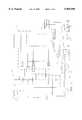
- FIG. 1is an electrical schematic showing an equalization circuit of the present invention in its environment for charging and monitoring a battery pack powering a motor load;
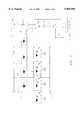
- FIG. 2shows a circuit diagram for a cell circuit of the equalization circuit
- FIG. 3shows a circuit diagram of the "AND” circuit and the "OR” circuit of the equalization circuit
- FIG. 4shows an electric scooter having the battery pack, equalizer circuit, controller and motor.
- the equalizer 20is connected to an equalization controller 24 which, in the preferred embodiment, is a Motorola MC68HC11.
- the controller 24receives inputs from OR circuitry 28 and AND circuitry 30 of the equalizer 20, via lines 32 and 34, respectively.
- the OR circuitryoutputs an active signal when any one of cells has reached a predetermined state
- the AND circuitryoutputs an active signal when all of the cells have reached a predetermined state.
- FIG. 1shows a switch SW1 connected to the controller 24.
- Switch SW1is closed when the ignition of the scooter is turned on by a user.
- the controller 24is connected to an auxiliary power source 36.
- auxiliary power source 36is a battery or other power source other than those belonging to the battery pack 22.
- the controller 24 controllerexecutes an initialization sequence. As part of this sequence, the controller 24 outputs an enable signal on line 26 and enables the cells Ei. This causes each cell to measure the battery voltage in its corresponding battery Bi within the battery pack 22. If any battery Bi has a voltage that is below a predetermined threshold, its corresponding cell Ei outputs a signal reflective of the low voltage condition. After outputting the enable signal during system initialization, the controller 24 monitors the outputs of the OR circuit to determine whether any of the batteries Bi has a low voltage.
- the controllerwill signal another unit 38, which may be an LED, or other display known in the art, to signify that the battery pack needs to be recharged.
- Unit 38may instead be a second controller which may make further use of this information. Since at least one of the batteries is low, Power relay RY1, which is a Kilovac EV250-2A-01, is not enabled by the controller, even if all other system checks indicate that the scooter is ready to be started and driven. This prevents operation of the scooter in situations where there is considerable chance that the user may not be able to complete a significant portion of the trip.
- the controller 24If, on the other hand, none of the batteries is determined to be low during initialization, and all other system checks are okay, the controller 24 outputs a signal on line 40 to enable the power relay RY1.
- the power relay RY1When the power relay RY1 is enabled, it connects power from the battery pack 22 to a motor controller 42, which is a solid state pulse-width modulating integrated controller.
- the motor controller 42provides 3-phase power to the motor 44, preferably a PM brushless dc skewed-slot motor with 3-phase windings.
- the energized motor 44is operatively connected to drive the scooter.
- the controller 24intermittently, and preferable periodically, enables the cells Ei to gauge the voltage of the batteries. If any of the batteries is low, this is determined by the controller 24 via line 32. The controller then outputs a warning signal to the display 38 to advise the user that the battery pack needs to be recharged, or, under certain conditions, will completely shut down scooter operation in order to prevent damage to the batteries.
- FIG. 1further illustrates a battery charger 46 connectable in parallel to the battery pack 22 via a connector represented by nodes A1, A2 and A3, wherein A2 and A3 are tied together within the connector.
- a 120 volt AC source 50such as a standard wall outlet, although alternate power sources may be used, as well.
- controller 24When the charger 46 is connected to battery pack 22 via a connector containing nodes A1 and A2, a ground at node A3 signals controller 24 via a line 52 that a charge cycle is to begin. Controller 24 now closes relay 49 via line 49 so that the charger 46 can begin charging the battery pack 22.
- the controller 24monitors the output of the AND circuit 30 to determine when all of the batteries Bi have become fully charged. Once all batteries have been charged, the controller signals charging relay 49 to open via line 48, thus breaking the connection between charger 46 and battery pack 22.
- the charger 46may be onboard the scooter, which allows one to recharge the scooter's battery pack virtually anywhere by plugging into a wall socket. However, due to weight and size limitations, it may be more economical to provide a commercially-available stand-alone charger. In the latter case, the charger can be electrically connected to opposite ends of the battery pack at nodes A1 and A2.
- the controller 24 and charger 46cooperate to charge the battery pack 22 in two stages.
- the 12 volt batteriesare charged at a constant voltage for approximately 4-5 hours to take them to approximately 80% of full charge, based on bringing a battery pack comprising 10 batteries to a total of 147 volts.
- a constant current of about 0.5 ampsis applied for about 1-2 hours to bring all the batteries to a voltage of 15.6 volts.
- the equalizer 20functions during this second, constant current portion of this charging sequence.
- FIG. 2shows one of the cells Ei of the equalizer 20.
- the nodes P and N on the left side of the cell Eidesignate the connections to the positive and negative terminals, respectively, of corresponding battery Bi.
- the batteries Biare connected in series, the negative terminal of one battery is connected to the positive terminal of the one below it, as seen in FIG. 1.
- the cells Eiare "stacked" atop one another, node N of one cell also serving as node P of the cell below it.
- Cell Eihas a dual role. First, while the scooter is being operated, but is in a quiescent state (low or zero current draw from the battery pack, such as upon starting, or at a stop light), cell Ei is used to monitor battery Bi for a low voltage differential ("low voltage detection") between nodes P and N ("P-N voltage"). Monitoring is done during the quiescent state to avoid artificially "low” battery readings which are due to momentary high load currents. Second, during a constant current phase of a charging operation, cell Ei is used to detect a high voltage condition and regulate the charging currents of battery Bi ("current regulation") by diverting a portion of the charging current to bypass battery Bi, if it is sufficiently charged. Both of these roles are performed with the cooperation of the controller 24 which enables the cell Ei via line 26
- the voltage monitor 60has a relative ground input 62, a supply voltage input 64, signal input 66 and an signal output 68 which is active low.
- Resistors R1 and R2are selected such that the supply voltage at input 64 to the voltage monitor is less than 12 volts, at a maximum expected P-N voltage of 15.6 volts.
- Capacitor C1 and resistor R2together form a filter to remove voltage fluctuations at supply voltage input 64.
- Resistors R3 and R4are 1% tolerance resistors, and are selected based on the predetermined threshold voltage at which the voltage monitor 60 is set to trip. The low tolerances for R3 and R4 are needed to ensure precision in setting this predetermined threshold. Capacitor C2 and resistor R4 together form a filter, much as do components C1 and R2.
- the threshold voltageis set to 10 volts, and so the output 68 remains high so long as the P-N voltage is greater than 10 volts. Under these conditions, node N1 is kept high, i.e., remains at the P-N voltage. Once the P-N voltage drops below this level, node N1 goes low, i.e., goes to relative ground.
- the controller 24To determine whether the P-N voltage is less than 10 volts, the controller 24 first enables first optocoupler Q1, which is an NEC 2702 switch. This is done via line 26. When the P-N voltage is less than 10 volts and the optocoupler Q1 is enabled, current flows through R6, through Q1's transistor portion, through R5, and is sunk to relative ground at voltage monitor's signal output 68.
- NPN transistor T2which is a Motorola 2N4401.
- T2When the base voltage of T2 exceeds its emitter voltage by approximately 0.6 volts, T2 will turn and begin to conduct. As R8 is 2.7 ⁇ , T2 will turn on when a current of about 222 mA passes through R8. Thus, switch T2 turns on, only when the current bypassing the battery exceeds a predetermined amperage, a "current bypass condition".
- Table 1presents the preferred component values for the resistors and capacitors used in the equalizer cell of FIG. 2.
- the low voltage detectionis performed intermittently during quiescent states. More particularly, the controller 24 operates the first optocoupler switch Q1 in a first mode in which Q1 is activated with short pulses of predetermined length on line 26, at periodic intervals.
- the pulseshould be long enough to account for the rise and settling time of the various components activated. In the preferred embodiment, a pulse length of 5 msec and a pulse repetition interval of 5 seconds are used. This ensures fairly regular monitoring for a low voltage condition.
- cell Eialso performs current regulation during the constant current phase of a charging procedure. This function is facilitated by controller 24, which again enables optocoupler Q1, and Zener diode Z1 which is selected for its breakdown voltage.
- Diode Z1is connected between nodes N and N1, as shown in FIG. 2. Thus, the anode of the Z1 and the output of the voltage monitor 60 share the same node. And when the N1-N voltage exceeds this value, Z1 begins to conduct.
- diode Z1effectively acts as a high voltage detector, and trips when the P-N voltage exceeds a predetermined threshold based on Z1's breakdown voltage, Q1's collector-emitter voltage and the voltage drop across R6.
- the constant current phaseis entered after the batteries Bi have already been charged for some time during a constant voltage phase.
- all the batterieswill have P-N voltages of at least 10 volts, and so the voltage monitor's output 68 is high.
- the controller 24operates the first optocoupler switch Q1 in a second mode in which Q1 is continuously activated, as a total charging current of 0.5 amps is provided to the battery pack 22 at node A1.
- the constant currentpasses through all the batteries.
- any one of the battery voltagesi.e., the corresponding P-N voltage
- its N1-N voltageapproaches the Z1's breakdown voltage, as there is a drop across Q1.
- the predetermined maximum voltage dropis about 14.8 volts
- the drop across Q1is about 1.5 volts
- Z1's breakdown voltageis about 13.3 volts.
- T2turns on, enabling second optocoupler switch Q2, as before. Therefore, when the corresponding battery has been charged to the predetermined maximum charging voltage, the transistor portion of Q2 outputs a status signal to the AND circuit signifying that the Zener breakdown voltage has been exceeded and that this battery is fully charged.
- substantially the same circuitry within a cell Eiis used to signal both a low voltage condition during the quiescent mode of scooter operation, as well as a high voltage (i.e., fully charged) condition during current regulation while in a constant current charging phase.
- this circuitryshunts current between adjacent cells to equalize the charge on the batteries in a battery pack.
- the same optocoupler switch Q1is operated in a first mode when cell Ei is to detect a low voltage condition, and in a second mode when cell Ei is to detect a high voltage (fully charged) condition and shunt current around its corresponding battery Bi in response thereto.
- FIG. 3shows the OR 28 and the AND 30 circuitry used in the present invention. This figure depicts a number of Q2s, each belonging to a different cell Ei. On its transistor side, the collector input of a Q2 is connected to an auxiliary power source 70 via pull-up resistor R11. In the preferred embodiment, auxiliary power source 70 is a 12 volt battery, and can be the same battery as 36.
- the emitters of Q2's transistor portionare connected to the OR circuit 28. If no optocoupler Q2 is enabled, no current flows through any of Q2's emitters. Thus, there is no current flow through R16 and so the base-emitter junction of Q4, which is also a 2N4401 is not forward biased. Therefore, Q4 does not conduct, and no current passes through pull-up resistor R15. As a result, node N5 remains high, and this information is presented to controller 24 via line 32.
- any one, or more, optocouplersis enabled, there will be a current flowing through R16. This will forward bias Q4's base-emitter junction and Q4 will conduct. A current passes through R15 and most of the +V drops across this resistor. As a result, node N5 goes low when one, or more, of the optocouplers Q2 are enabled, and this information is presented to controller 24 via line 32.
- the collectors of Q2's transistor portionare connected to the AND circuit 30 through diodes D3. If any one of the Q2s are not enabled, then the auxiliary supply voltage of +V will draw current through resistor R11, and also through diode D3. As all diodes D3 are connected to R12, the current through R12 and R13 will forward bias Q3's base-emitter junction causing Q3 to conduct, resulting in a voltage drop across R14. Under these conditions, node N4 is low, and this information is presented to controller 24 via line 34. It is important to note that current through any one of the R11 resistors is sufficient to cause Q3 to conduct.
- FIG. 4shows an electric scooter 80 equipped with the circuitry discussed above, depicted in FIG. 4 as block diagrams.
- the equalizer circuitry 20, controller 24, relay RY1 and motor controller 42are all situated beneath the battery compartment 82 in a separate chamber 84.
- all four of these componentsare provided on one or more printed circuit boards to facilitate installation and maintenance.
- a user actionsuch as turning of a key, closes switch SW1.
- controller 24This begins the initialization sequence of controller 24, which includes testing the voltage condition of the batteries. If no battery is determined to have a low voltage, and the remaining scooter systems are okay, the controller signals the power relay RY1 to close, which connects battery pack 22 to motor controller 42. Otherwise, power is not connected to motor controller, and scooter operation is prohibited.
- the controller 24While the scooter is being driven, during quiescent periods, the controller 24 operates first optocoupler switch Q1 in the first mode in which it is intermittently enabled and the cells of the equalizer circuit check for a low voltage condition.
- the controllermonitors the equalizer's OR circuit output, as described above. Should any one battery be found to have low voltage, a warning signal is displayed on display 38, and the user is allowed to complete the ride.
- controller 24does not enable first optocoupler Q1, and the voltage condition of the batteries is not monitored.
- the controller 24operates the first optocoupler switch Q1 in the second mode in which it is continuously enabled, and the cells of the equalizer circuit check for a high voltage condition, signifying that a corresponding battery is fully charged.
- the controller 24monitors the equalizer's AND circuit. If all batteries meet the high voltage condition, the controller 24 signals that the constant current phase of the charging operation has been completed.
Landscapes
- Engineering & Computer Science (AREA)
- Power Engineering (AREA)
- Life Sciences & Earth Sciences (AREA)
- Sustainable Development (AREA)
- Sustainable Energy (AREA)
- Transportation (AREA)
- Mechanical Engineering (AREA)
- Charge And Discharge Circuits For Batteries Or The Like (AREA)
Abstract
Description
TABLE 1 ______________________________________ Component Values Component Value ______________________________________ R1 330KΩ R2 1MΩ R3 768KΩ, 1% R4 105KΩ, 1% R5 3.3KΩ R6 2.2KΩ R7 4.7 Ω R8 2.7 Ω R9 4.7KΩ C1 0.01 μF C2 0.01 μF ______________________________________
Claims (4)
Priority Applications (1)
| Application Number | Priority Date | Filing Date | Title |
|---|---|---|---|
| US08/989,174US5965996A (en) | 1997-12-11 | 1997-12-11 | Electrical scooter having an equalization circuit for charging multiple batteries |
Applications Claiming Priority (1)
| Application Number | Priority Date | Filing Date | Title |
|---|---|---|---|
| US08/989,174US5965996A (en) | 1997-12-11 | 1997-12-11 | Electrical scooter having an equalization circuit for charging multiple batteries |
Publications (1)
| Publication Number | Publication Date |
|---|---|
| US5965996Atrue US5965996A (en) | 1999-10-12 |
Family
ID=25534836
Family Applications (1)
| Application Number | Title | Priority Date | Filing Date |
|---|---|---|---|
| US08/989,174Expired - LifetimeUS5965996A (en) | 1997-12-11 | 1997-12-11 | Electrical scooter having an equalization circuit for charging multiple batteries |
Country Status (1)
| Country | Link |
|---|---|
| US (1) | US5965996A (en) |
Cited By (57)
| Publication number | Priority date | Publication date | Assignee | Title |
|---|---|---|---|---|
| US6326765B1 (en) | 2000-10-04 | 2001-12-04 | Vectrix Corporation | Electric scooter with on-board charging system |
| US6410992B1 (en) | 2000-08-23 | 2002-06-25 | Capstone Turbine Corporation | System and method for dual mode control of a turbogenerator/motor |
| US6664653B1 (en) | 1998-10-27 | 2003-12-16 | Capstone Turbine Corporation | Command and control system for controlling operational sequencing of multiple turbogenerators using a selected control mode |
| US20040018419A1 (en)* | 2002-07-24 | 2004-01-29 | Nissan Motor Co., Ltd. | Control for battery pack |
| US6930404B1 (en)* | 2001-10-12 | 2005-08-16 | Ford Global Technologies, Llc | Power supply for an automotive vehicle |
| US20060043797A1 (en)* | 2004-08-31 | 2006-03-02 | American Power Conversion Corporation | Method and apparatus for providing uninterruptible power |
| US20060077603A1 (en)* | 2004-09-07 | 2006-04-13 | Kim Jong S | Protective circuit for a secondary battery pack and method of operating the same |
| US20060097697A1 (en)* | 2004-11-10 | 2006-05-11 | Eaglepicher Technologies, Llc | Method and system for cell equalization with switched charging sources |
| US20060097696A1 (en)* | 2004-11-10 | 2006-05-11 | Eaglepicher Technologies, Llc | Method and system for cell equalization with isolated charging sources |
| US20060097700A1 (en)* | 2004-11-10 | 2006-05-11 | Eaglepicher Technologies, Llc | Method and system for cell equalization with charging sources and shunt regulators |
| US20060279255A1 (en)* | 2005-06-13 | 2006-12-14 | Nissan Motor Co., Ltd. | Chargeable-and-dischargeable power supply system |
| WO2007145463A1 (en)* | 2006-06-15 | 2007-12-21 | Sk Energy Co., Ltd. | Charge equalization apparatus |
| WO2007145459A1 (en)* | 2006-06-15 | 2007-12-21 | Sk Energy Co., Ltd. | Charge equalization apparatus with parallel connection of primary windings of multiple transformers |
| WO2007145464A1 (en)* | 2006-06-15 | 2007-12-21 | Sk Energy Co., Ltd. | Charge equalization apparatus and method |
| WO2007145460A1 (en)* | 2006-06-15 | 2007-12-21 | Sk Energy Co., Ltd. | Charge equalization apparatus with parallel connection of secondary windings of multiple transformers |
| WO2008055505A1 (en)* | 2006-11-10 | 2008-05-15 | Lithium Balance A/S | A battery management system |
| EP1988404A1 (en)* | 2007-05-03 | 2008-11-05 | Erun Sàrl | Device for transmitting management information of a power battery |
| US20090033283A1 (en)* | 2007-08-03 | 2009-02-05 | Mirza Akmal Beg | Adjustable battery charger for ups |
| EP2028742A1 (en)* | 2007-08-24 | 2009-02-25 | Nesscap. Co. Ltd. | Method of monitoring voltage for energy storage device and apparatus using the method |
| US20090123814A1 (en)* | 2007-10-09 | 2009-05-14 | Mason Cabot | Power source and method of managing a power source |
| US20090224769A1 (en)* | 2004-04-30 | 2009-09-10 | Akihiko Emori | Multi-Series Battery Control System |
| US20090261785A1 (en)* | 2008-03-27 | 2009-10-22 | Mason Cabot | Method for managing a modular power source |
| US20090263708A1 (en)* | 2008-04-02 | 2009-10-22 | Josh Bender | System and method of integrated thermal management for a multi-cell battery pack |
| US20100133030A1 (en)* | 2008-11-20 | 2010-06-03 | Karl Johnson | Frame for a ride-on vehicle having a plurality of battery packs |
| US20100136405A1 (en)* | 2008-04-02 | 2010-06-03 | Karl Johnson | Battery pack with optimized mechanical, electrical, and thermal management |
| US20110006737A1 (en)* | 2009-07-10 | 2011-01-13 | Narayana Prakash Saligram | Battery charging method and apparatus |
| US20110074355A1 (en)* | 2010-11-04 | 2011-03-31 | Elite Power Solutions, LLC | Battery unit balancing system |
| US20110084650A1 (en)* | 2009-10-09 | 2011-04-14 | Charles Industries, Ltd. | Battery charger |
| EP2332819A1 (en) | 2006-06-14 | 2011-06-15 | Vectrix International Limited | Contactless throttle control apparatus |
| EP2345576A1 (en) | 2006-04-26 | 2011-07-20 | Vectrix International Limited | Vehicle with lockable tilt system |
| US20110175467A1 (en)* | 2010-01-19 | 2011-07-21 | Brian Belton | Coolant system for electric motorcycle |
| US20110177371A1 (en)* | 2010-01-19 | 2011-07-21 | Brian Belton | Battery system for electric motorcycle |
| CN101582594B (en)* | 2008-05-16 | 2011-07-27 | 富港电子(东莞)有限公司 | Charging control circuit |
| WO2011138726A3 (en)* | 2010-05-07 | 2012-04-12 | Brusa Elektronik Ag | Method and cell monitoring unit for monitoring an accumulator; central monitoring unit and accumulator |
| US20120118659A1 (en)* | 2010-11-11 | 2012-05-17 | Honda Motor Co., Ltd. | Saddle-ride-type electrically operated vehicle |
| US20120133310A1 (en)* | 2009-07-02 | 2012-05-31 | Chong Uk Lee | Reconfigurable battery |
| CN101795010B (en)* | 2009-12-31 | 2012-07-18 | 惠州市亿能电子有限公司 | Lithium battery protection method |
| US20120194134A1 (en)* | 2011-01-31 | 2012-08-02 | Infineon Technologies Ag | Inductive Charge Balancing |
| WO2012110185A1 (en)* | 2011-02-16 | 2012-08-23 | Sew-Eurodrive Gmbh & Co. Kg | Device, in particular electric vehicle, lifting mechanism, shelf-rack serving unit with lifting mechanism or fork lift truck, with energy accumulator |
| WO2012110186A1 (en)* | 2011-02-16 | 2012-08-23 | Sew-Eurodrive Gmbh & Co. Kg | Charger for an accumulator |
| US20120256568A1 (en)* | 2009-07-02 | 2012-10-11 | Chong Uk Lee | Multi-port reconfigurable battery |
| US8312954B2 (en) | 2010-04-22 | 2012-11-20 | Mission Motor Company | Frame for a two wheeled electric vehicle |
| US20130057777A1 (en)* | 2011-09-01 | 2013-03-07 | Echostar Technologies L.L.C. | Detecting batteries with non-uniform drain rates |
| US20130234827A1 (en)* | 2012-03-08 | 2013-09-12 | Omron Automotive Electronics Co., Ltd. | Communication system and portable machine |
| US20130257383A1 (en)* | 2012-04-03 | 2013-10-03 | Kyung-Sub Shim | Battery Pack, Method of Measuring Voltage of the Battery Pack, and Energy Storage System Including the Battery Pack |
| EP2595275A4 (en)* | 2010-07-14 | 2014-03-26 | Yazaki Corp | VOLTAGE EQUALIZATION APPARATUS FOR ASSEMBLED BATTERY |
| CN103730935A (en)* | 2013-12-30 | 2014-04-16 | 广东志成冠军集团有限公司 | Equalization circuit for allowing electric energy of lithium batteries to be uniform |
| WO2014130260A1 (en)* | 2013-02-19 | 2014-08-28 | Faster Faster Inc. | Battery housing |
| US20150048794A1 (en)* | 2012-03-29 | 2015-02-19 | Soongsil University Research Conscortum Techno-Park | Battery charge balancing device and battery charge balancing system |
| CN104698895A (en)* | 2015-03-18 | 2015-06-10 | 西平立至电控科技有限公司 | Compatible integrated circuit control method and control device for electric vehicle controller |
| US20150325886A1 (en)* | 2012-12-11 | 2015-11-12 | Robert Bosch Gmbh | Battery Management System and Battery System |
| CN108068638A (en)* | 2016-11-16 | 2018-05-25 | 台达电子工业股份有限公司 | Electric vehicle charging equipment and charging method |
| US20210036523A1 (en)* | 2018-01-25 | 2021-02-04 | Volvo Construction Equipment Ab | Equalizer overload management |
| US11005276B2 (en) | 2018-01-23 | 2021-05-11 | Solsona Enterprise, Llc | Stacked variable voltage battery module arrangement |
| WO2021238547A1 (en)* | 2020-05-29 | 2021-12-02 | 华为技术有限公司 | Battery charging method, electronic apparatus, storage medium and program product |
| US20230006459A1 (en)* | 2021-06-30 | 2023-01-05 | Ablic Inc. | Charge control circuit, charge control device, and battery device |
| US11855476B2 (en)* | 2019-12-20 | 2023-12-26 | Lg Electronics Inc. | Charger and control method thereof |
Citations (18)
| Publication number | Priority date | Publication date | Assignee | Title |
|---|---|---|---|---|
| US5467007A (en)* | 1992-09-16 | 1995-11-14 | Matsushita Electric Industrial Co., Ltd. | Charging apparatus |
| US5483144A (en)* | 1993-03-08 | 1996-01-09 | Marek; Albert | Passive battery charging system |
| US5504415A (en)* | 1993-12-03 | 1996-04-02 | Electronic Power Technology, Inc. | Method and apparatus for automatic equalization of series-connected batteries |
| US5539297A (en)* | 1992-05-15 | 1996-07-23 | Robert Bosch Gmbh | Charging device for charging a plurality of batteries based on parameter priority |
| US5557189A (en)* | 1993-12-24 | 1996-09-17 | Sony Corporation | Method and apparatus including a current detector and a power source control circuit for charging a number of batteries |
| US5561360A (en)* | 1994-05-02 | 1996-10-01 | General Motors Corporation | Battery cycle life improvements through bifurcated recharge method |
| US5576608A (en)* | 1993-05-14 | 1996-11-19 | Sony Corporation | Method for charging secondary battery and charger used therefor |
| US5578914A (en)* | 1994-06-08 | 1996-11-26 | Nissan Motor Co., Ltd. | Charging system for multi-cell battery |
| US5592067A (en)* | 1994-01-06 | 1997-01-07 | General Motors Corporation | Distributed multi-module battery equalization |
| US5602481A (en)* | 1994-03-11 | 1997-02-11 | Nissan Motor Co., Ltd. | Series connection circuit for secondary battery |
| US5637979A (en)* | 1992-08-27 | 1997-06-10 | Sanyo Electric Co., Ltd. | Rechargeable battery charging method and apparatus |
| US5640079A (en)* | 1994-08-29 | 1997-06-17 | Andrew Corporation | Battery charger for portable rechargeable batteries |
| US5642031A (en)* | 1994-02-28 | 1997-06-24 | Black & Decker Inc. | Battery recharging system with state of charge detection that initially detects whether a battery to be charged is already at or near full charge to prevent overcharging |
| US5642029A (en)* | 1994-03-03 | 1997-06-24 | Sgs-Thomson Microelectronics S.R.L. | Constant current battery charger with auxiliary output for portable apparatus |
| US5644210A (en)* | 1994-12-28 | 1997-07-01 | Samsung Electronics Co., Ltd. | Charging control method and circuit of recharging battery |
| US5646504A (en)* | 1994-04-15 | 1997-07-08 | Feldstein; Robert S. | Magnetically balanced multi-output battery charging system |
| US5646507A (en)* | 1993-10-22 | 1997-07-08 | Douglas Battery Manufacturing Company | Battery charger system |
| US5659240A (en)* | 1995-02-16 | 1997-08-19 | General Electric Company | Intelligent battery charger for electric drive system batteries |
- 1997
- 1997-12-11USUS08/989,174patent/US5965996A/ennot_activeExpired - Lifetime
Patent Citations (18)
| Publication number | Priority date | Publication date | Assignee | Title |
|---|---|---|---|---|
| US5539297A (en)* | 1992-05-15 | 1996-07-23 | Robert Bosch Gmbh | Charging device for charging a plurality of batteries based on parameter priority |
| US5637979A (en)* | 1992-08-27 | 1997-06-10 | Sanyo Electric Co., Ltd. | Rechargeable battery charging method and apparatus |
| US5467007A (en)* | 1992-09-16 | 1995-11-14 | Matsushita Electric Industrial Co., Ltd. | Charging apparatus |
| US5483144A (en)* | 1993-03-08 | 1996-01-09 | Marek; Albert | Passive battery charging system |
| US5576608A (en)* | 1993-05-14 | 1996-11-19 | Sony Corporation | Method for charging secondary battery and charger used therefor |
| US5646507A (en)* | 1993-10-22 | 1997-07-08 | Douglas Battery Manufacturing Company | Battery charger system |
| US5504415A (en)* | 1993-12-03 | 1996-04-02 | Electronic Power Technology, Inc. | Method and apparatus for automatic equalization of series-connected batteries |
| US5557189A (en)* | 1993-12-24 | 1996-09-17 | Sony Corporation | Method and apparatus including a current detector and a power source control circuit for charging a number of batteries |
| US5592067A (en)* | 1994-01-06 | 1997-01-07 | General Motors Corporation | Distributed multi-module battery equalization |
| US5642031A (en)* | 1994-02-28 | 1997-06-24 | Black & Decker Inc. | Battery recharging system with state of charge detection that initially detects whether a battery to be charged is already at or near full charge to prevent overcharging |
| US5642029A (en)* | 1994-03-03 | 1997-06-24 | Sgs-Thomson Microelectronics S.R.L. | Constant current battery charger with auxiliary output for portable apparatus |
| US5602481A (en)* | 1994-03-11 | 1997-02-11 | Nissan Motor Co., Ltd. | Series connection circuit for secondary battery |
| US5646504A (en)* | 1994-04-15 | 1997-07-08 | Feldstein; Robert S. | Magnetically balanced multi-output battery charging system |
| US5561360A (en)* | 1994-05-02 | 1996-10-01 | General Motors Corporation | Battery cycle life improvements through bifurcated recharge method |
| US5578914A (en)* | 1994-06-08 | 1996-11-26 | Nissan Motor Co., Ltd. | Charging system for multi-cell battery |
| US5640079A (en)* | 1994-08-29 | 1997-06-17 | Andrew Corporation | Battery charger for portable rechargeable batteries |
| US5644210A (en)* | 1994-12-28 | 1997-07-01 | Samsung Electronics Co., Ltd. | Charging control method and circuit of recharging battery |
| US5659240A (en)* | 1995-02-16 | 1997-08-19 | General Electric Company | Intelligent battery charger for electric drive system batteries |
Cited By (117)
| Publication number | Priority date | Publication date | Assignee | Title |
|---|---|---|---|---|
| US6664653B1 (en) | 1998-10-27 | 2003-12-16 | Capstone Turbine Corporation | Command and control system for controlling operational sequencing of multiple turbogenerators using a selected control mode |
| US6410992B1 (en) | 2000-08-23 | 2002-06-25 | Capstone Turbine Corporation | System and method for dual mode control of a turbogenerator/motor |
| US6664654B2 (en) | 2000-08-23 | 2003-12-16 | Capstone Turbine Corporation | System and method for dual mode control of a turbogenerator/motor |
| US6326765B1 (en) | 2000-10-04 | 2001-12-04 | Vectrix Corporation | Electric scooter with on-board charging system |
| EP2301790A2 (en) | 2000-10-04 | 2011-03-30 | Vectrix International Limited | Electric scooter with on-board charging system |
| EP2301790A3 (en)* | 2000-10-04 | 2013-01-02 | Vectrix International Limited | Electric scooter with on-board charging system |
| US6930404B1 (en)* | 2001-10-12 | 2005-08-16 | Ford Global Technologies, Llc | Power supply for an automotive vehicle |
| US7138775B2 (en)* | 2002-07-24 | 2006-11-21 | Nissan Motor Co., Ltd. | Control for battery pack |
| US20040018419A1 (en)* | 2002-07-24 | 2004-01-29 | Nissan Motor Co., Ltd. | Control for battery pack |
| US8791668B2 (en) | 2004-04-30 | 2014-07-29 | Shin-Kobe Electric Machinery Co., Ltd. | Multi-series battery control system |
| US20090224769A1 (en)* | 2004-04-30 | 2009-09-10 | Akihiko Emori | Multi-Series Battery Control System |
| US8884584B2 (en) | 2004-04-30 | 2014-11-11 | Shin-Kobe Electric Machinery Co., Ltd. | Multi-series battery control system |
| US8786256B2 (en) | 2004-04-30 | 2014-07-22 | Shin-Kobe Electric Machinery Co., Ltd. | Multi-series battery control system |
| US8912756B2 (en) | 2004-04-30 | 2014-12-16 | Shin-Kobe Electric Machinery Co., Ltd. | Multi-series battery control system |
| US8339099B2 (en)* | 2004-04-30 | 2012-12-25 | Shin-Kobe Electric Machinery Co., Ltd. | Multi-series battery control system |
| US20110227415A1 (en)* | 2004-08-31 | 2011-09-22 | American Power Conversion Corporation | Method and apparatus for providing uninterruptible power |
| US7855472B2 (en) | 2004-08-31 | 2010-12-21 | American Power Conversion Corporation | Method and apparatus for providing uninterruptible power |
| US20100225170A1 (en)* | 2004-08-31 | 2010-09-09 | American Power Conversion Corporation | Method and apparatus for providing uninterruptible power |
| US7737580B2 (en)* | 2004-08-31 | 2010-06-15 | American Power Conversion Corporation | Method and apparatus for providing uninterruptible power |
| US20060043797A1 (en)* | 2004-08-31 | 2006-03-02 | American Power Conversion Corporation | Method and apparatus for providing uninterruptible power |
| US8053927B2 (en) | 2004-08-31 | 2011-11-08 | American Power Conversion Corporation | Method and apparatus for providing uninterruptible power |
| US7583060B2 (en)* | 2004-09-07 | 2009-09-01 | Samsung Sdi Co., Ltd. | Protective circuit for a secondary battery pack and method of operating the same |
| US20060077603A1 (en)* | 2004-09-07 | 2006-04-13 | Kim Jong S | Protective circuit for a secondary battery pack and method of operating the same |
| US20090309544A1 (en)* | 2004-11-10 | 2009-12-17 | Eaglepicher Technologies, Llc | Method and system for cell equalization with switched charging sources |
| US7821230B2 (en) | 2004-11-10 | 2010-10-26 | EaglePicher Technologies | Method and system for cell equalization with switched charging sources |
| US20060097700A1 (en)* | 2004-11-10 | 2006-05-11 | Eaglepicher Technologies, Llc | Method and system for cell equalization with charging sources and shunt regulators |
| US20060097696A1 (en)* | 2004-11-10 | 2006-05-11 | Eaglepicher Technologies, Llc | Method and system for cell equalization with isolated charging sources |
| US20090267565A1 (en)* | 2004-11-10 | 2009-10-29 | Eaglepicher Technologies, Llc | Method and system for cell equalization with charging sources and shunt regulators |
| US20060097697A1 (en)* | 2004-11-10 | 2006-05-11 | Eaglepicher Technologies, Llc | Method and system for cell equalization with switched charging sources |
| US7928691B2 (en)* | 2004-11-10 | 2011-04-19 | EaglePicher Technologies | Method and system for cell equalization with isolated charging sources |
| US7825629B2 (en) | 2004-11-10 | 2010-11-02 | EaglePicher Technologies | Method and system for cell equalization with charging sources and shunt regulators |
| US20060279255A1 (en)* | 2005-06-13 | 2006-12-14 | Nissan Motor Co., Ltd. | Chargeable-and-dischargeable power supply system |
| US7554291B2 (en)* | 2005-06-13 | 2009-06-30 | Nissan Motor Co., Ltd. | Battery control system for a chargeable-and-dischargeable power supply system |
| EP2345576A1 (en) | 2006-04-26 | 2011-07-20 | Vectrix International Limited | Vehicle with lockable tilt system |
| EP2332818A1 (en) | 2006-06-14 | 2011-06-15 | Vectrix International Limited | Contactless throttle control apparatus |
| EP2332819A1 (en) | 2006-06-14 | 2011-06-15 | Vectrix International Limited | Contactless throttle control apparatus |
| WO2007145464A1 (en)* | 2006-06-15 | 2007-12-21 | Sk Energy Co., Ltd. | Charge equalization apparatus and method |
| US20090322155A1 (en)* | 2006-06-15 | 2009-12-31 | Sk Energy Co., Ltd. | Charge of equalization apparatus with parallel connection of secondary windings of multiple transformers |
| CN101467325B (en)* | 2006-06-15 | 2012-08-29 | Sk新技术株式会社 | Charge equalization apparatus and method |
| US20100283433A1 (en)* | 2006-06-15 | 2010-11-11 | Sk Energy Co., Ltd. | Charge equalization apparatus with parallel connection of primary windings of multiple transformers |
| WO2007145459A1 (en)* | 2006-06-15 | 2007-12-21 | Sk Energy Co., Ltd. | Charge equalization apparatus with parallel connection of primary windings of multiple transformers |
| WO2007145463A1 (en)* | 2006-06-15 | 2007-12-21 | Sk Energy Co., Ltd. | Charge equalization apparatus |
| US7880433B2 (en) | 2006-06-15 | 2011-02-01 | Sk Energy Co., Ltd. | Charge equalization apparatus |
| US8217623B2 (en) | 2006-06-15 | 2012-07-10 | Sk Energy Co. Ltd. | Charge equalization apparatus and method |
| US8766598B2 (en) | 2006-06-15 | 2014-07-01 | Sk Innovation Co., Ltd. | Charge equalization apparatus with parallel connection of primary windings of multiple transformers |
| US20090237030A1 (en)* | 2006-06-15 | 2009-09-24 | Sk Energy Co., Ltd. | Charge equalization apparatus |
| CN101467324B (en)* | 2006-06-15 | 2012-02-15 | Sk新技术株式会社 | Charge equalization apparatus with parallel connection of secondary windings of multiple transformers |
| US7939965B2 (en) | 2006-06-15 | 2011-05-10 | Sk Energy Co., Ltd. | Charge of equalization apparatus with parallel connection of secondary windings of multiple transformers |
| CN101467326B (en)* | 2006-06-15 | 2011-12-28 | Sk新技术株式会社 | Charge equalization apparatus with parallel connection of primary coils of multiple transformers |
| US20090302803A1 (en)* | 2006-06-15 | 2009-12-10 | Sk Energy Co., Ltd. | Charge equalization apparatus and method |
| WO2007145460A1 (en)* | 2006-06-15 | 2007-12-21 | Sk Energy Co., Ltd. | Charge equalization apparatus with parallel connection of secondary windings of multiple transformers |
| US7982429B1 (en) | 2006-06-15 | 2011-07-19 | Sk Energy Co., Ltd. | Charge equalization apparatus |
| EP2092627B1 (en) | 2006-11-10 | 2018-05-23 | Lithium Balance A/S | A battery management system |
| WO2008055505A1 (en)* | 2006-11-10 | 2008-05-15 | Lithium Balance A/S | A battery management system |
| US20100052615A1 (en)* | 2006-11-10 | 2010-03-04 | Ivan Loncarevic | Battery management system |
| US12003124B2 (en) | 2006-11-10 | 2024-06-04 | Lithium Balance A/S | Battery management system |
| US8350529B2 (en) | 2006-11-10 | 2013-01-08 | Lithium Balance A/S | Battery management system |
| US10396570B2 (en) | 2006-11-10 | 2019-08-27 | Lithium Balance A/S | Battery management system with temperature sensing and charge management for individual series-connected battery cells |
| US10862317B2 (en) | 2006-11-10 | 2020-12-08 | Lithium Balance A/S | Battery management system with temperature sensing and charge management for individual series-connected battery cells |
| EP1988404A1 (en)* | 2007-05-03 | 2008-11-05 | Erun Sàrl | Device for transmitting management information of a power battery |
| US7944182B2 (en) | 2007-08-03 | 2011-05-17 | American Power Conversion Corporation | Adjustable battery charger for UPS |
| US20090033283A1 (en)* | 2007-08-03 | 2009-02-05 | Mirza Akmal Beg | Adjustable battery charger for ups |
| EP2028742A1 (en)* | 2007-08-24 | 2009-02-25 | Nesscap. Co. Ltd. | Method of monitoring voltage for energy storage device and apparatus using the method |
| US20090123814A1 (en)* | 2007-10-09 | 2009-05-14 | Mason Cabot | Power source and method of managing a power source |
| US20090261785A1 (en)* | 2008-03-27 | 2009-10-22 | Mason Cabot | Method for managing a modular power source |
| US20090263708A1 (en)* | 2008-04-02 | 2009-10-22 | Josh Bender | System and method of integrated thermal management for a multi-cell battery pack |
| US20100136405A1 (en)* | 2008-04-02 | 2010-06-03 | Karl Johnson | Battery pack with optimized mechanical, electrical, and thermal management |
| CN101582594B (en)* | 2008-05-16 | 2011-07-27 | 富港电子(东莞)有限公司 | Charging control circuit |
| US20100133030A1 (en)* | 2008-11-20 | 2010-06-03 | Karl Johnson | Frame for a ride-on vehicle having a plurality of battery packs |
| US8316976B2 (en) | 2008-11-20 | 2012-11-27 | Mission Motor Company | Frame for a ride-on vehicle having a plurality of battery packs |
| US20120256568A1 (en)* | 2009-07-02 | 2012-10-11 | Chong Uk Lee | Multi-port reconfigurable battery |
| US8957610B2 (en)* | 2009-07-02 | 2015-02-17 | Chong Uk Lee | Multi-port reconfigurable battery |
| US8816613B2 (en)* | 2009-07-02 | 2014-08-26 | Chong Uk Lee | Reconfigurable battery |
| US20120133310A1 (en)* | 2009-07-02 | 2012-05-31 | Chong Uk Lee | Reconfigurable battery |
| US8581554B2 (en) | 2009-07-10 | 2013-11-12 | Schneider Electric It Corporation | Battery charging method and apparatus |
| US20110006737A1 (en)* | 2009-07-10 | 2011-01-13 | Narayana Prakash Saligram | Battery charging method and apparatus |
| US20110084650A1 (en)* | 2009-10-09 | 2011-04-14 | Charles Industries, Ltd. | Battery charger |
| CN101795010B (en)* | 2009-12-31 | 2012-07-18 | 惠州市亿能电子有限公司 | Lithium battery protection method |
| US20110175467A1 (en)* | 2010-01-19 | 2011-07-21 | Brian Belton | Coolant system for electric motorcycle |
| US8212438B2 (en) | 2010-01-19 | 2012-07-03 | U.S. Alternate Energy, LLC | Coolant system for electric motorcycle |
| US8455128B2 (en)* | 2010-01-19 | 2013-06-04 | U.S. Alternative Energy, LLC | Battery system for electric motorcycle |
| US20110177371A1 (en)* | 2010-01-19 | 2011-07-21 | Brian Belton | Battery system for electric motorcycle |
| US8312954B2 (en) | 2010-04-22 | 2012-11-20 | Mission Motor Company | Frame for a two wheeled electric vehicle |
| WO2011138726A3 (en)* | 2010-05-07 | 2012-04-12 | Brusa Elektronik Ag | Method and cell monitoring unit for monitoring an accumulator; central monitoring unit and accumulator |
| EP2595275A4 (en)* | 2010-07-14 | 2014-03-26 | Yazaki Corp | VOLTAGE EQUALIZATION APPARATUS FOR ASSEMBLED BATTERY |
| US8723482B2 (en)* | 2010-11-04 | 2014-05-13 | Elite Power Solutions Llc | Battery unit balancing system |
| US20110074355A1 (en)* | 2010-11-04 | 2011-03-31 | Elite Power Solutions, LLC | Battery unit balancing system |
| US8668037B2 (en)* | 2010-11-11 | 2014-03-11 | Honda Motor Co., Ltd. | Saddle-ride-type electrically operated vehicle |
| US20120118659A1 (en)* | 2010-11-11 | 2012-05-17 | Honda Motor Co., Ltd. | Saddle-ride-type electrically operated vehicle |
| US8791667B2 (en)* | 2011-01-31 | 2014-07-29 | Infineon Technologies Ag | Inductive charge balancing |
| US9423450B2 (en) | 2011-01-31 | 2016-08-23 | Infineon Technologies Ag | Inductive charge balancing |
| US20120194134A1 (en)* | 2011-01-31 | 2012-08-02 | Infineon Technologies Ag | Inductive Charge Balancing |
| WO2012110185A1 (en)* | 2011-02-16 | 2012-08-23 | Sew-Eurodrive Gmbh & Co. Kg | Device, in particular electric vehicle, lifting mechanism, shelf-rack serving unit with lifting mechanism or fork lift truck, with energy accumulator |
| WO2012110186A1 (en)* | 2011-02-16 | 2012-08-23 | Sew-Eurodrive Gmbh & Co. Kg | Charger for an accumulator |
| US20130057777A1 (en)* | 2011-09-01 | 2013-03-07 | Echostar Technologies L.L.C. | Detecting batteries with non-uniform drain rates |
| US9748784B2 (en)* | 2011-09-01 | 2017-08-29 | Echostar Technologies L.L.C. | Detecting batteries with non-uniform drain rates |
| US20130234827A1 (en)* | 2012-03-08 | 2013-09-12 | Omron Automotive Electronics Co., Ltd. | Communication system and portable machine |
| US9105182B2 (en)* | 2012-03-08 | 2015-08-11 | Omron Automotive Electronics Co., Ltd. | Communication system and portable machine |
| US20150048794A1 (en)* | 2012-03-29 | 2015-02-19 | Soongsil University Research Conscortum Techno-Park | Battery charge balancing device and battery charge balancing system |
| US9722435B2 (en)* | 2012-03-29 | 2017-08-01 | Soongsil University Research Conscortum Techno-Park | Battery charge balancing device and battery charge balancing system |
| US9065296B2 (en)* | 2012-04-03 | 2015-06-23 | Samsung Sdi Co., Ltd. | Battery pack, method of measuring voltage of the battery pack, and energy storage system including the battery pack |
| US20130257383A1 (en)* | 2012-04-03 | 2013-10-03 | Kyung-Sub Shim | Battery Pack, Method of Measuring Voltage of the Battery Pack, and Energy Storage System Including the Battery Pack |
| US20150325886A1 (en)* | 2012-12-11 | 2015-11-12 | Robert Bosch Gmbh | Battery Management System and Battery System |
| US9840157B2 (en)* | 2012-12-11 | 2017-12-12 | Robert Bosch Gmbh | Battery management system and battery system |
| WO2014130260A1 (en)* | 2013-02-19 | 2014-08-28 | Faster Faster Inc. | Battery housing |
| CN103730935B (en)* | 2013-12-30 | 2016-04-27 | 广东志成冠军集团有限公司 | A kind ofly realize the consistent equalizing circuit of lithium battery electric energy |
| CN103730935A (en)* | 2013-12-30 | 2014-04-16 | 广东志成冠军集团有限公司 | Equalization circuit for allowing electric energy of lithium batteries to be uniform |
| CN104698895A (en)* | 2015-03-18 | 2015-06-10 | 西平立至电控科技有限公司 | Compatible integrated circuit control method and control device for electric vehicle controller |
| CN108068638A (en)* | 2016-11-16 | 2018-05-25 | 台达电子工业股份有限公司 | Electric vehicle charging equipment and charging method |
| CN108068638B (en)* | 2016-11-16 | 2020-06-05 | 台达电子工业股份有限公司 | Electric vehicle charging equipment and charging method |
| US11005276B2 (en) | 2018-01-23 | 2021-05-11 | Solsona Enterprise, Llc | Stacked variable voltage battery module arrangement |
| US20210036523A1 (en)* | 2018-01-25 | 2021-02-04 | Volvo Construction Equipment Ab | Equalizer overload management |
| US11768232B2 (en)* | 2018-01-25 | 2023-09-26 | Volvo Construction Equipment Ab | Equalizer overload management |
| US11855476B2 (en)* | 2019-12-20 | 2023-12-26 | Lg Electronics Inc. | Charger and control method thereof |
| WO2021238547A1 (en)* | 2020-05-29 | 2021-12-02 | 华为技术有限公司 | Battery charging method, electronic apparatus, storage medium and program product |
| US20230006459A1 (en)* | 2021-06-30 | 2023-01-05 | Ablic Inc. | Charge control circuit, charge control device, and battery device |
| US12424859B2 (en)* | 2021-06-30 | 2025-09-23 | Ablic Inc. | Charge control circuit, charge control device, and battery device |
Similar Documents
| Publication | Publication Date | Title |
|---|---|---|
| US5965996A (en) | Electrical scooter having an equalization circuit for charging multiple batteries | |
| US5387857A (en) | Battery charging apparauts | |
| US7368829B2 (en) | Method and apparatus for detecting welding of a relay contact | |
| US7019488B2 (en) | Battery power source device of electric power vehicle | |
| US5504415A (en) | Method and apparatus for automatic equalization of series-connected batteries | |
| AU771405B2 (en) | Portable jump-starting battery pack with charge monitoring system | |
| US5469042A (en) | Charging monitor for electrical accumulators | |
| US5345163A (en) | Battery monitoring system | |
| US10877104B2 (en) | Ground fault detection apparatus | |
| US20110140665A1 (en) | Power supply device capable of forcedly discharging battery cell | |
| KR102062743B1 (en) | High voltage battery system for vehicle applications | |
| WO2011148926A1 (en) | Power supply device | |
| GB2312571A (en) | Charging series connected batteries | |
| US5805068A (en) | Cordless device with battery imbalance indicator | |
| JPH0564377A (en) | Assembled battery charger | |
| US11218009B2 (en) | Tool circuitry for series-type connected battery packs | |
| CN215894889U (en) | Control circuit capable of detecting short circuit break of LED, charging seat and electric vehicle | |
| US20250026238A1 (en) | Balancing States of Charge of Battery Modules for an Electric Vehicle | |
| JPH07264780A (en) | Battery charge / discharge control device | |
| JP2002238179A (en) | Rechargeable battery charger and charging method | |
| KR20230064207A (en) | Pparatus for controllign battery connection and battery system including the same | |
| JP3408062B2 (en) | Method and device for charging secondary battery | |
| EP0502437A2 (en) | A device for determining the charge condition of batteries, in particular on board a vehicle | |
| KR890000843Y1 (en) | Charge / discharge control circuit of storage battery | |
| JPH01243827A (en) | Power source circuit for power tool driven by both charging and alternating current |
Legal Events
| Date | Code | Title | Description |
|---|---|---|---|
| AS | Assignment | Owner name:VECTRIX CORPORATION, RHODE ISLAND Free format text:ASSIGNMENT OF ASSIGNORS INTEREST;ASSIGNORS:ARLEDGE, ARTHUR L.;DOBROWSKI, RUSSELL G.;HUGHES, PETER S.;AND OTHERS;REEL/FRAME:009142/0592;SIGNING DATES FROM 19980206 TO 19980304 | |
| STCF | Information on status: patent grant | Free format text:PATENTED CASE | |
| FPAY | Fee payment | Year of fee payment:4 | |
| FPAY | Fee payment | Year of fee payment:8 | |
| AS | Assignment | Owner name:NEW VECTRIX LLC, AS LENDER, PENNSYLVANIA Free format text:PATENT SECURITY AGREEMENT;ASSIGNOR:VECTRIX CORPORATION;REEL/FRAME:023304/0204 Effective date:20090924 Owner name:NEW VECTRIX LLC, AS LENDER,PENNSYLVANIA Free format text:PATENT SECURITY AGREEMENT;ASSIGNOR:VECTRIX CORPORATION;REEL/FRAME:023304/0204 Effective date:20090924 | |
| FEPP | Fee payment procedure | Free format text:PAT HOLDER CLAIMS SMALL ENTITY STATUS, ENTITY STATUS SET TO SMALL (ORIGINAL EVENT CODE: LTOS); ENTITY STATUS OF PATENT OWNER: LARGE ENTITY | |
| AS | Assignment | Owner name:VECTRIX INTERNATIONAL LIMITED,HONG KONG Free format text:ASSIGNMENT OF ASSIGNORS INTEREST;ASSIGNOR:VECTRIX CORPORATION;REEL/FRAME:024529/0380 Effective date:20100524 Owner name:VECTRIX INTERNATIONAL LIMITED, HONG KONG Free format text:ASSIGNMENT OF ASSIGNORS INTEREST;ASSIGNOR:VECTRIX CORPORATION;REEL/FRAME:024529/0380 Effective date:20100524 | |
| FPAY | Fee payment | Year of fee payment:12 | |
| FEPP | Fee payment procedure | Free format text:PAT HOLDER NO LONGER CLAIMS SMALL ENTITY STATUS, ENTITY STATUS SET TO UNDISCOUNTED (ORIGINAL EVENT CODE: STOL); ENTITY STATUS OF PATENT OWNER: LARGE ENTITY |