US5965967A - Rotor for an electrical machine - Google Patents
Rotor for an electrical machineDownload PDFInfo
- Publication number
- US5965967A US5965967AUS09/110,353US11035398AUS5965967AUS 5965967 AUS5965967 AUS 5965967AUS 11035398 AUS11035398 AUS 11035398AUS 5965967 AUS5965967 AUS 5965967A
- Authority
- US
- United States
- Prior art keywords
- pole
- rotor
- finger
- permanent magnets
- adjacent
- Prior art date
- Legal status (The legal status is an assumption and is not a legal conclusion. Google has not performed a legal analysis and makes no representation as to the accuracy of the status listed.)
- Expired - Fee Related
Links
Images

Classifications
- H—ELECTRICITY
- H02—GENERATION; CONVERSION OR DISTRIBUTION OF ELECTRIC POWER
- H02K—DYNAMO-ELECTRIC MACHINES
- H02K21/00—Synchronous motors having permanent magnets; Synchronous generators having permanent magnets
- H02K21/02—Details
- H02K21/04—Windings on magnets for additional excitation ; Windings and magnets for additional excitation
- H02K21/042—Windings on magnets for additional excitation ; Windings and magnets for additional excitation with permanent magnets and field winding both rotating
- H02K21/044—Rotor of the claw pole type
- Y—GENERAL TAGGING OF NEW TECHNOLOGICAL DEVELOPMENTS; GENERAL TAGGING OF CROSS-SECTIONAL TECHNOLOGIES SPANNING OVER SEVERAL SECTIONS OF THE IPC; TECHNICAL SUBJECTS COVERED BY FORMER USPC CROSS-REFERENCE ART COLLECTIONS [XRACs] AND DIGESTS
- Y10—TECHNICAL SUBJECTS COVERED BY FORMER USPC
- Y10T—TECHNICAL SUBJECTS COVERED BY FORMER US CLASSIFICATION
- Y10T29/00—Metal working
- Y10T29/49—Method of mechanical manufacture
- Y10T29/49002—Electrical device making
- Y10T29/49009—Dynamoelectric machine
- Y10T29/49012—Rotor
Definitions
- the present inventionrelates to electrical machines, and more particularly to rotors having wound-field and permanent magnet excitation.
- the design of the '577 patentcan provide advantages over standard Lundell rotors, the tangential magnetization of the permanent magnets may not make optimal use of the expensive permanent magnets. That is, pure tangential magnetization may miss opportunities to have some direct linking of permanent magnet flux with the stator windings. Such linking may provide benefits in the form of higher electrical output and higher power density (i.e., power output per unit volume of the alternator) of the alternator.
- the present inventionprovides a rotor for an electrical machine, the rotor having an axis of rotation and comprising a first pole piece having a plurality of axially-extending first pole fingers and a second pole piece having a plurality of axially-extending second pole fingers, the first pole fingers alternately intermeshed with the second pole fingers.
- the rotoralso includes a field coil in electromagnetic communication with the first pole piece and the second pole piece which when energized magnetizes the first pole fingers and the second pole fingers.
- the rotorcomprises a plurality of permanent magnets, each disposed between a first pole finger and an adjacent second pole finger and having a magnetization polarity at an angle between radial and tangential with respect to the axis of rotation of the rotor.
- the present inventionprovides a rotor for an electrical machine, the rotor having an axis of rotation and comprising a first pole piece having a plurality of axially-extending first pole fingers and a second pole piece having a plurality of axially-extending second pole fingers, the first pole fingers alternately intermeshed with the second pole fingers.
- the rotoralso includes a field coil in electromagnetic communication with the first pole piece and the second pole piece which when energized magnetizes the first pole fingers and the second pole fingers.
- the rotorcomprises a plurality of permanent magnets, each disposed between a first pole finger and an adjacent second pole finger and having a radially-outward surface and an adjacent tangentially-facing surface of a first electromagnetic polarity and having a radially-inward surface and an adjacent tangentially-facing surface of an opposite magnetic polarity.
- the present inventionalso provides a method of manufacturing a rotor for an electrical machine, the rotor having a first pole piece with a plurality of first axially-extending pole fingers and a second pole piece with a plurality of second axially-extending pole fingers and an axis of rotation.
- the methodcomprises assembling the first pole piece and the second pole piece with the first pole fingers alternately intermeshed with the second pole fingers and at least one permanent magnet disposed between each first pole finger and an adjacent second pole finger.
- the methodalso includes magnetizing the permanent magnets to each have a magnetization polarity with an angle between radial and tangential with respect to the axis of rotation of the rotor.
- FIG. 1is an exploded view of the relevant components of a "claw pole", or Lundell, rotor.
- FIG. 2is a side view of a rotor according to the present invention and of a corresponding stator 40 of an alternator.
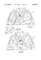
- FIGS. 3 and 4are partial end views of the rotor of FIG. 2, from opposite ends of the rotor.
- FIG. 5is a perspective view of permanent magnet 34A of FIG. 3.
- pole pieces 20 and 22are mounted for rotation on shaft 26.
- Pole pieces 20 and 22each include a disk-shaped body 28, a hub 30 and a plurality of axially-extending pole fingers 32.
- field coil 24 of the embodiment of the present invention hereinafter describedis preferably driven by unidirectional current controlled by a voltage regulator.
- FIGS. 2, 3 and 4.each illustrate a rotor 33 according to one embodiment of the present invention.
- the rotorincludes known pole pieces 20 and 22. Disposed between pole fingers 32 are permanent magnets 34. Each permanent magnet 34 is preferably mounted to its two adjacent pole fingers 32 by adhesive or by another suitable fastening method.
- FIGS. 2-4also illustrate fans 36 and 38, which are preferably stamped steel fans attached to pole pieces 20 and 22, respectively, and well-known in the art.
- FIG. 2illustrates in cross-section stator 40 of the electrical machine, including stator windings 42. Rotor 33 and stator 40 are separated by an air gap 44.
- FIGS. 3-5Magnetization polarity of permanent magnets 34 is best illustrated in FIGS. 3-5.
- Permanent magnets 34are magnetized with a polarity which runs diagonally across their cross sections, as is shown by the arrows on permanent magnets 34A-34D.
- the radially-outward surfaceis of south magnetic polarity, as is the adjacent surface which faces tangentially to the right (as viewed in FIG. 3).
- the radially-inward surface and the adjacent surface which faces tangentially to the leftare of north magnetic polarity.
- FIG. 5shows permanent magnet 34A removed from rotor 33.
- the radially-outward surface and the surface facing tangentially to the rightare of north magnetic polarity.
- the radially-inward surface and the adjacent surface which faces tangentially to the leftare of south magnetic polarity.
- Pole finger 32A(a pole finger of north magnetic polarity when magnetized by field coil 24) and pole finger 32B (a pole finger of south magnetic polarity when magnetized by field coil 24) will strongly tend to demagnetize a permanent magnet included therebetween which is magnetized in a purely tangential direction. Such a tendency is less where the magnetization polarity is not purely tangential, such as with permanent magnets 34.
- Permanent magnets 34can be magnetized by applying magnetic field to the magnets in the manner described as follows. To magnetize the magnets whose radially-outward surface is of south magnetic polarity, such as 34A and 34B, the north pole of the magnetizing fixture should contact the radially-outward surface of those magnets and the south pole of the magnetizing fixture should contact the rotor pole piece whose pole fingers 32 are of north magnetic polarity. Similarly, to magnetize the magnets whose radially-outward surface is of north magnetic polarity, such as 34C and 34D, the south pole of the magnetizing fixture should contact the radially-outward surfaces of those magnets and the north pole of the magnetizing fixture should contact the rotor pole piece whose pole fingers 32 are of south magnetic polarity.
- the magnetizing fixturecan directly contact one the pole surfaces of the permanent magnets, most of the magnetizing flux generated by the magnetizer can go though the permanent magnets as desired and there is little ⁇ leakage flux ⁇ which goes through the rotor hub and therefore bypasses the permanent magnets being magnetized.
- permanent magnets 34can also be magnetized prior to assembly of rotor 33.
- the magnetswill be much more difficult to assemble into the rotor because the magnets will be attracted to any ferromagnetic material in their vicinity.
- two permanent magnets 34are located adjacent each tip of a pole finger 32. This is illustrated, for example, by permanent magnets 34C and 34D and pole finger 32A.
- the radially outward surfaces of the two permanent magnets 34are preferably of the same magnetic polarity of the pole finger 32 whose tip the permanent magnets are adjacent.
- the two permanent magnets which are adjacent to a tip of a pole finger 32help to maximize the magnetized surface area of the rotor. That is, where the tip of a pole finger 32 has narrowed to a narrow tip, the rotor surface area which can generate electromagnetic flux linking with stator windings 42 is reduced. Placing two permanent magnets 34 on the two sides of the pole finger tip increases the area which was reduced due to the narrowing of the pole finger.
- the narrowingwhich is not in itself preferred from the standpoint of optimizing flux linkage between the rotor and the stator, is nonetheless a typical feature in Lundell alternators due to other design considerations.
- Permanent magnets 34are manufactured to have a structure which supports magnetization with a polarity as illustrated in FIGS. 3-5 and previously discussed. If an isotropic permanent magnet material is used the direction of the magnetization axis is determined by the magnetization process. By controlling the direction of the magnetizing flux the magnetization axis of the permanent magnets can be oriented to the desired direction. If an anisotropic material is used the orientation of the magnetization axis is controlled in the manufacturing process of the permanent magnets. By controlling the direction of the applied magnetic field while the magnet is pressed the direction of the magnetization axis can be oriented to the desired direction.
Landscapes
- Engineering & Computer Science (AREA)
- Power Engineering (AREA)
- Permanent Field Magnets Of Synchronous Machinery (AREA)
Abstract
Description
Claims (20)
Priority Applications (1)
| Application Number | Priority Date | Filing Date | Title |
|---|---|---|---|
| US09/110,353US5965967A (en) | 1998-07-06 | 1998-07-06 | Rotor for an electrical machine |
Applications Claiming Priority (1)
| Application Number | Priority Date | Filing Date | Title |
|---|---|---|---|
| US09/110,353US5965967A (en) | 1998-07-06 | 1998-07-06 | Rotor for an electrical machine |
Publications (1)
| Publication Number | Publication Date |
|---|---|
| US5965967Atrue US5965967A (en) | 1999-10-12 |
Family
ID=22332554
Family Applications (1)
| Application Number | Title | Priority Date | Filing Date |
|---|---|---|---|
| US09/110,353Expired - Fee RelatedUS5965967A (en) | 1998-07-06 | 1998-07-06 | Rotor for an electrical machine |
Country Status (1)
| Country | Link |
|---|---|
| US (1) | US5965967A (en) |
Cited By (11)
| Publication number | Priority date | Publication date | Assignee | Title |
|---|---|---|---|---|
| US6359366B1 (en) | 2000-05-09 | 2002-03-19 | Ford Global Technologies, Inc. | Hybrid permanent magnet/synchronous machines |
| US20020047425A1 (en)* | 2000-05-03 | 2002-04-25 | Moteurs Leroy-Somer | Rotary electric machine having a flux-concentrating rotor and a stator with windings on teeth |
| US6396181B1 (en)* | 1999-03-26 | 2002-05-28 | Valeo Equipements Electriques Moteur | Rotating maching with advanced excitation means |
| US20020163278A1 (en)* | 2001-04-17 | 2002-11-07 | Moteurs Leroy-Somer | Rotary electric machine having a stator made up of sectors assembled together |
| US20020171305A1 (en)* | 2001-04-17 | 2002-11-21 | Moteurs Leroy-Somer | Electric machine having an outer rotor |
| US20020196385A1 (en)* | 2001-06-20 | 2002-12-26 | Zhan He | Backlight units for liquid crystal displays |
| US6573634B2 (en)* | 2001-06-01 | 2003-06-03 | Ut-Battelle, Llc | Method and machine for high strength undiffused brushless operation |
| US6683397B2 (en) | 2001-04-17 | 2004-01-27 | Moteurs Leroy-Somer | Electric machine having at least one magnetic field detector |
| US6703741B1 (en) | 1999-09-20 | 2004-03-09 | Ecoair Corp. | Permanent magnet rotor portion for electric machines |
| US20050057106A1 (en)* | 2002-12-10 | 2005-03-17 | Ballard Power Systems Corporation | Methods and systems for electric machines having windings |
| DE102011085429A1 (en)* | 2011-10-28 | 2013-05-02 | Robert Bosch Gmbh | Electric machine, in particular alternator |
Citations (20)
| Publication number | Priority date | Publication date | Assignee | Title |
|---|---|---|---|---|
| US3346749A (en)* | 1965-02-02 | 1967-10-10 | Trw Inc | Self-excited brushless alternator |
| US3392294A (en)* | 1964-07-08 | 1968-07-09 | Gen Motors Corp | Alternating current generator |
| US3411027A (en)* | 1965-07-15 | 1968-11-12 | Siemens Ag | Permanent magnet excited electric machine |
| US3553510A (en)* | 1967-07-07 | 1971-01-05 | Lucas Industries Ltd | Rotor for permanent magnet alternator |
| US3555327A (en)* | 1969-03-25 | 1971-01-12 | Ambac Ind | Permanent magnet alternator with regulating means |
| US4433261A (en)* | 1982-03-24 | 1984-02-21 | Kabushiki Kaisha Okuma Tekkosho | Rotor for permanent magnet type synchronous motors |
| US4584496A (en)* | 1984-03-23 | 1986-04-22 | Robert Bosch Gmbh | Internally force-ventilated claw-pole alternator, particularly for automotive use |
| US4855630A (en)* | 1988-05-05 | 1989-08-08 | A. O. Smith Corporation | Permanent magnet rotor with magnet retention band |
| US4882515A (en)* | 1988-06-03 | 1989-11-21 | General Motors Corporation | Alternating current generator |
| US4930201A (en)* | 1985-08-14 | 1990-06-05 | Kollmorgen Corporation | Method for manufacturing a composite sleeve for an electric motor |
| US4959577A (en)* | 1989-10-23 | 1990-09-25 | General Motors Corporation | Alternating current generator |
| US4972114A (en)* | 1987-02-11 | 1990-11-20 | Robert Bosch Gmbh | Alternating-current generator with claw pole rotor |
| US4980595A (en)* | 1987-11-23 | 1990-12-25 | Chrysler Corporation | Multiple magnetic paths machine |
| US5047680A (en)* | 1987-12-09 | 1991-09-10 | Astra-Tech Ab | Rotating electrical machine |
| US5130595A (en)* | 1987-11-23 | 1992-07-14 | Chrysler Corporation | Multiple magnetic paths machine |
| US5132581A (en)* | 1990-02-26 | 1992-07-21 | Nippondenso Co., Ltd. | AC generator with annular permanent magnets |
| US5177391A (en)* | 1990-03-14 | 1993-01-05 | Nippondenso Co., Ltd. | Power generating apparatus |
| US5298827A (en)* | 1991-11-26 | 1994-03-29 | Mitsubishi Denki Kabushiki Kaisha | Permanent magnet type dynamoelectric machine rotor |
| US5382862A (en)* | 1992-07-20 | 1995-01-17 | General Motors Corporation | Alternating current generator rotor |
| US5543676A (en)* | 1995-03-16 | 1996-08-06 | Ford Motor Company | Rotating electrical machine with magnetic inserts |
- 1998
- 1998-07-06USUS09/110,353patent/US5965967A/ennot_activeExpired - Fee Related
Patent Citations (20)
| Publication number | Priority date | Publication date | Assignee | Title |
|---|---|---|---|---|
| US3392294A (en)* | 1964-07-08 | 1968-07-09 | Gen Motors Corp | Alternating current generator |
| US3346749A (en)* | 1965-02-02 | 1967-10-10 | Trw Inc | Self-excited brushless alternator |
| US3411027A (en)* | 1965-07-15 | 1968-11-12 | Siemens Ag | Permanent magnet excited electric machine |
| US3553510A (en)* | 1967-07-07 | 1971-01-05 | Lucas Industries Ltd | Rotor for permanent magnet alternator |
| US3555327A (en)* | 1969-03-25 | 1971-01-12 | Ambac Ind | Permanent magnet alternator with regulating means |
| US4433261A (en)* | 1982-03-24 | 1984-02-21 | Kabushiki Kaisha Okuma Tekkosho | Rotor for permanent magnet type synchronous motors |
| US4584496A (en)* | 1984-03-23 | 1986-04-22 | Robert Bosch Gmbh | Internally force-ventilated claw-pole alternator, particularly for automotive use |
| US4930201A (en)* | 1985-08-14 | 1990-06-05 | Kollmorgen Corporation | Method for manufacturing a composite sleeve for an electric motor |
| US4972114A (en)* | 1987-02-11 | 1990-11-20 | Robert Bosch Gmbh | Alternating-current generator with claw pole rotor |
| US5130595A (en)* | 1987-11-23 | 1992-07-14 | Chrysler Corporation | Multiple magnetic paths machine |
| US4980595A (en)* | 1987-11-23 | 1990-12-25 | Chrysler Corporation | Multiple magnetic paths machine |
| US5047680A (en)* | 1987-12-09 | 1991-09-10 | Astra-Tech Ab | Rotating electrical machine |
| US4855630A (en)* | 1988-05-05 | 1989-08-08 | A. O. Smith Corporation | Permanent magnet rotor with magnet retention band |
| US4882515A (en)* | 1988-06-03 | 1989-11-21 | General Motors Corporation | Alternating current generator |
| US4959577A (en)* | 1989-10-23 | 1990-09-25 | General Motors Corporation | Alternating current generator |
| US5132581A (en)* | 1990-02-26 | 1992-07-21 | Nippondenso Co., Ltd. | AC generator with annular permanent magnets |
| US5177391A (en)* | 1990-03-14 | 1993-01-05 | Nippondenso Co., Ltd. | Power generating apparatus |
| US5298827A (en)* | 1991-11-26 | 1994-03-29 | Mitsubishi Denki Kabushiki Kaisha | Permanent magnet type dynamoelectric machine rotor |
| US5382862A (en)* | 1992-07-20 | 1995-01-17 | General Motors Corporation | Alternating current generator rotor |
| US5543676A (en)* | 1995-03-16 | 1996-08-06 | Ford Motor Company | Rotating electrical machine with magnetic inserts |
Cited By (14)
| Publication number | Priority date | Publication date | Assignee | Title |
|---|---|---|---|---|
| US6396181B1 (en)* | 1999-03-26 | 2002-05-28 | Valeo Equipements Electriques Moteur | Rotating maching with advanced excitation means |
| US6703741B1 (en) | 1999-09-20 | 2004-03-09 | Ecoair Corp. | Permanent magnet rotor portion for electric machines |
| US20020047425A1 (en)* | 2000-05-03 | 2002-04-25 | Moteurs Leroy-Somer | Rotary electric machine having a flux-concentrating rotor and a stator with windings on teeth |
| US6891299B2 (en)* | 2000-05-03 | 2005-05-10 | Moteurs Leroy-Somer | Rotary electric machine having a flux-concentrating rotor and a stator with windings on teeth |
| US6548931B2 (en) | 2000-05-09 | 2003-04-15 | Ballard Power Systems Corporation | Hybrid permanent magnet/synchronous machines |
| US6359366B1 (en) | 2000-05-09 | 2002-03-19 | Ford Global Technologies, Inc. | Hybrid permanent magnet/synchronous machines |
| US6683397B2 (en) | 2001-04-17 | 2004-01-27 | Moteurs Leroy-Somer | Electric machine having at least one magnetic field detector |
| US20020171305A1 (en)* | 2001-04-17 | 2002-11-21 | Moteurs Leroy-Somer | Electric machine having an outer rotor |
| US20020163278A1 (en)* | 2001-04-17 | 2002-11-07 | Moteurs Leroy-Somer | Rotary electric machine having a stator made up of sectors assembled together |
| US6975057B2 (en) | 2001-04-17 | 2005-12-13 | Moteurs Leroy-Somer | Rotary electric machine having a stator made up of sectors assembled together |
| US6573634B2 (en)* | 2001-06-01 | 2003-06-03 | Ut-Battelle, Llc | Method and machine for high strength undiffused brushless operation |
| US20020196385A1 (en)* | 2001-06-20 | 2002-12-26 | Zhan He | Backlight units for liquid crystal displays |
| US20050057106A1 (en)* | 2002-12-10 | 2005-03-17 | Ballard Power Systems Corporation | Methods and systems for electric machines having windings |
| DE102011085429A1 (en)* | 2011-10-28 | 2013-05-02 | Robert Bosch Gmbh | Electric machine, in particular alternator |
Similar Documents
| Publication | Publication Date | Title |
|---|---|---|
| US5543676A (en) | Rotating electrical machine with magnetic inserts | |
| US6548931B2 (en) | Hybrid permanent magnet/synchronous machines | |
| US5955807A (en) | Synchronous electric machine having auxiliary permanent magnet | |
| US5663605A (en) | Rotating electrical machine with electromagnetic and permanent magnet excitation | |
| JP4617046B2 (en) | Electric machine | |
| US7669311B2 (en) | Method of manufacturing a core for an electrical machine | |
| US6922000B2 (en) | Rotary electric machine | |
| US5892313A (en) | Rotating electrical machine with permanent magnet inserts | |
| EP0544310A2 (en) | Permanent magnet type dynamoelectric machine rotor | |
| EP0772279A1 (en) | AC generator for vehicle | |
| CN102593983A (en) | Rotating electrical machine | |
| US5965967A (en) | Rotor for an electrical machine | |
| US6437477B1 (en) | Hybrid electrical machine with axial flux magnet | |
| JP2003088071A (en) | Reluctance type rotating electric machine | |
| US6538358B1 (en) | Hybrid electrical machine with axially extending magnets | |
| US20040070303A1 (en) | Rotor assembly and method of making | |
| JPH0824420B2 (en) | Permanent magnet field type DC machine | |
| US6455978B1 (en) | Hybrid twin coil electrical machine | |
| JP2000050546A (en) | Rotor of permanent magnet motor | |
| CN1044178C (en) | Electric motor with combined magnetic pole of Nd-Fe-B permanent magnet and soft magnet | |
| JPH05236714A (en) | Permanent magnet type synchronous motor | |
| JP3776171B2 (en) | Magnet rotor | |
| JP2001359263A (en) | Synchronous machine serving both as magnet | |
| JP4066219B2 (en) | Synchronous machine with stationary field coil magnet | |
| JP2783264B2 (en) | AC generator |
Legal Events
| Date | Code | Title | Description |
|---|---|---|---|
| AS | Assignment | Owner name:FORD MOTOR COMPANY, MICHIGAN Free format text:ASSIGNMENT OF ASSIGNORS INTEREST;ASSIGNOR:MILLER, JOHN MICHAEL;REEL/FRAME:009465/0924 Effective date:19980707 Owner name:FORD MOTOR COMPANY, MICHIGAN Free format text:ASSIGNMENT OF ASSIGNORS INTEREST;ASSIGNORS:LIANG, FENG;XU, XINGYI;REEL/FRAME:009464/0410 Effective date:19980630 | |
| AS | Assignment | Owner name:FORD GLOBAL TECHNOLOGIES, INC., MICHIGAN Free format text:ASSIGNMENT OF ASSIGNORS INTEREST;ASSIGNOR:FORD MOTOR COMPANY;REEL/FRAME:009462/0612 Effective date:19980914 | |
| FPAY | Fee payment | Year of fee payment:4 | |
| AS | Assignment | Owner name:BALLARD POWER SYSTEMS CORPORATION, MICHIGAN Free format text:ASSIGNMENT OF ASSIGNORS INTEREST;ASSIGNOR:FORD GLOBAL TECHNOLOGIES, L.L.C.;REEL/FRAME:015008/0463 Effective date:20040109 | |
| FPAY | Fee payment | Year of fee payment:8 | |
| AS | Assignment | Owner name:SIEMENS VDO AUTOMOTIVE CORPORATION,MICHIGAN Free format text:CHANGE OF NAME;ASSIGNOR:BALLARD POWER SYSTEMS CORPORATION;REEL/FRAME:019077/0840 Effective date:20070215 Owner name:SIEMENS VDO AUTOMOTIVE CORPORATION, MICHIGAN Free format text:CHANGE OF NAME;ASSIGNOR:BALLARD POWER SYSTEMS CORPORATION;REEL/FRAME:019077/0840 Effective date:20070215 | |
| FEPP | Fee payment procedure | Free format text:PAYOR NUMBER ASSIGNED (ORIGINAL EVENT CODE: ASPN); ENTITY STATUS OF PATENT OWNER: LARGE ENTITY Free format text:PAYER NUMBER DE-ASSIGNED (ORIGINAL EVENT CODE: RMPN); ENTITY STATUS OF PATENT OWNER: LARGE ENTITY | |
| REMI | Maintenance fee reminder mailed | ||
| LAPS | Lapse for failure to pay maintenance fees | ||
| LAPS | Lapse for failure to pay maintenance fees | Free format text:PATENT EXPIRED FOR FAILURE TO PAY MAINTENANCE FEES (ORIGINAL EVENT CODE: EXP.); ENTITY STATUS OF PATENT OWNER: LARGE ENTITY | |
| STCH | Information on status: patent discontinuation | Free format text:PATENT EXPIRED DUE TO NONPAYMENT OF MAINTENANCE FEES UNDER 37 CFR 1.362 | |
| FP | Lapsed due to failure to pay maintenance fee | Effective date:20111012 |