US5965330A - Methods for fabricating annular mask lens having diffraction-reducing edges - Google Patents
Methods for fabricating annular mask lens having diffraction-reducing edgesDownload PDFInfo
- Publication number
- US5965330A US5965330AUS08/761,308US76130896AUS5965330AUS 5965330 AUS5965330 AUS 5965330AUS 76130896 AUS76130896 AUS 76130896AUS 5965330 AUS5965330 AUS 5965330A
- Authority
- US
- United States
- Prior art keywords
- lens
- central portion
- radiation
- transmissivity
- lens substrate
- Prior art date
- Legal status (The legal status is an assumption and is not a legal conclusion. Google has not performed a legal analysis and makes no representation as to the accuracy of the status listed.)
- Expired - Lifetime
Links
Images


Classifications
- G—PHYSICS
- G02—OPTICS
- G02C—SPECTACLES; SUNGLASSES OR GOGGLES INSOFAR AS THEY HAVE THE SAME FEATURES AS SPECTACLES; CONTACT LENSES
- G02C7/00—Optical parts
- G02C7/02—Lenses; Lens systems ; Methods of designing lenses
- G02C7/024—Methods of designing ophthalmic lenses
- G02C7/028—Special mathematical design techniques
- A—HUMAN NECESSITIES
- A61—MEDICAL OR VETERINARY SCIENCE; HYGIENE
- A61F—FILTERS IMPLANTABLE INTO BLOOD VESSELS; PROSTHESES; DEVICES PROVIDING PATENCY TO, OR PREVENTING COLLAPSING OF, TUBULAR STRUCTURES OF THE BODY, e.g. STENTS; ORTHOPAEDIC, NURSING OR CONTRACEPTIVE DEVICES; FOMENTATION; TREATMENT OR PROTECTION OF EYES OR EARS; BANDAGES, DRESSINGS OR ABSORBENT PADS; FIRST-AID KITS
- A61F2/00—Filters implantable into blood vessels; Prostheses, i.e. artificial substitutes or replacements for parts of the body; Appliances for connecting them with the body; Devices providing patency to, or preventing collapsing of, tubular structures of the body, e.g. stents
- A61F2/02—Prostheses implantable into the body
- A61F2/14—Eye parts, e.g. lenses or corneal implants; Artificial eyes
- A61F2/147—Implants to be inserted in the stroma for refractive correction, e.g. ring-like implants
- A—HUMAN NECESSITIES
- A61—MEDICAL OR VETERINARY SCIENCE; HYGIENE
- A61F—FILTERS IMPLANTABLE INTO BLOOD VESSELS; PROSTHESES; DEVICES PROVIDING PATENCY TO, OR PREVENTING COLLAPSING OF, TUBULAR STRUCTURES OF THE BODY, e.g. STENTS; ORTHOPAEDIC, NURSING OR CONTRACEPTIVE DEVICES; FOMENTATION; TREATMENT OR PROTECTION OF EYES OR EARS; BANDAGES, DRESSINGS OR ABSORBENT PADS; FIRST-AID KITS
- A61F2/00—Filters implantable into blood vessels; Prostheses, i.e. artificial substitutes or replacements for parts of the body; Appliances for connecting them with the body; Devices providing patency to, or preventing collapsing of, tubular structures of the body, e.g. stents
- A61F2/02—Prostheses implantable into the body
- A61F2/14—Eye parts, e.g. lenses or corneal implants; Artificial eyes
- A61F2/16—Intraocular lenses
- A61F2/1613—Intraocular lenses having special lens configurations, e.g. multipart lenses; having particular optical properties, e.g. pseudo-accommodative lenses, lenses having aberration corrections, diffractive lenses, lenses for variably absorbing electromagnetic radiation, lenses having variable focus
- B—PERFORMING OPERATIONS; TRANSPORTING
- B29—WORKING OF PLASTICS; WORKING OF SUBSTANCES IN A PLASTIC STATE IN GENERAL
- B29D—PRODUCING PARTICULAR ARTICLES FROM PLASTICS OR FROM SUBSTANCES IN A PLASTIC STATE
- B29D11/00—Producing optical elements, e.g. lenses or prisms
- B29D11/00009—Production of simple or compound lenses
- B29D11/00038—Production of contact lenses
- B—PERFORMING OPERATIONS; TRANSPORTING
- B29—WORKING OF PLASTICS; WORKING OF SUBSTANCES IN A PLASTIC STATE IN GENERAL
- B29D—PRODUCING PARTICULAR ARTICLES FROM PLASTICS OR FROM SUBSTANCES IN A PLASTIC STATE
- B29D11/00—Producing optical elements, e.g. lenses or prisms
- B29D11/00009—Production of simple or compound lenses
- B29D11/00317—Production of lenses with markings or patterns
- B—PERFORMING OPERATIONS; TRANSPORTING
- B29—WORKING OF PLASTICS; WORKING OF SUBSTANCES IN A PLASTIC STATE IN GENERAL
- B29D—PRODUCING PARTICULAR ARTICLES FROM PLASTICS OR FROM SUBSTANCES IN A PLASTIC STATE
- B29D11/00—Producing optical elements, e.g. lenses or prisms
- B29D11/00865—Applying coatings; tinting; colouring
- B29D11/00923—Applying coatings; tinting; colouring on lens surfaces for colouring or tinting
- G—PHYSICS
- G02—OPTICS
- G02C—SPECTACLES; SUNGLASSES OR GOGGLES INSOFAR AS THEY HAVE THE SAME FEATURES AS SPECTACLES; CONTACT LENSES
- G02C7/00—Optical parts
- G02C7/16—Shades; shields; Obturators, e.g. with pinhole, with slot
- G—PHYSICS
- G03—PHOTOGRAPHY; CINEMATOGRAPHY; ANALOGOUS TECHNIQUES USING WAVES OTHER THAN OPTICAL WAVES; ELECTROGRAPHY; HOLOGRAPHY
- G03F—PHOTOMECHANICAL PRODUCTION OF TEXTURED OR PATTERNED SURFACES, e.g. FOR PRINTING, FOR PROCESSING OF SEMICONDUCTOR DEVICES; MATERIALS THEREFOR; ORIGINALS THEREFOR; APPARATUS SPECIALLY ADAPTED THEREFOR
- G03F7/00—Photomechanical, e.g. photolithographic, production of textured or patterned surfaces, e.g. printing surfaces; Materials therefor, e.g. comprising photoresists; Apparatus specially adapted therefor
- G03F7/0005—Production of optical devices or components in so far as characterised by the lithographic processes or materials used therefor
- G03F7/001—Phase modulating patterns, e.g. refractive index patterns
- G—PHYSICS
- G02—OPTICS
- G02C—SPECTACLES; SUNGLASSES OR GOGGLES INSOFAR AS THEY HAVE THE SAME FEATURES AS SPECTACLES; CONTACT LENSES
- G02C2202/00—Generic optical aspects applicable to one or more of the subgroups of G02C7/00
- G02C2202/04—Lenses comprising decentered structures
Definitions
- This inventionconcerns a lens for vision correction and, in particular, masked lenses and related methodology.
- Contact lensesare commonplace today. Most individuals with average refractive errors can quickly and easily acquire and use these lenses in place of prescription eye glasses. This is not true, however, for individuals who are presbyopic (i.e., those requiring multi-focal visual correction) or for those individuals with structural eye abnormalities. These individuals are left with little choice in selecting comfortable, effective contact lenses. Lenses which are available typically encumber these wearers with other difficulties, and are usually very expensive. Presbyopic individuals, for example, who choose to wear soft contact lenses are usually fitted in a "monovision" mode, where one eye is corrected for near vision, and the other eye is corrected for far vision. Notwithstanding the availability of multifocal lenses, such lenses are not versatile in supplying simultaneous clear distance/near vision and are not commercially successful.
- pinhole contact lensese.g., PCT Publication No. WO95/08135 published Mar. 23, 1995. These lenses endeavor to utilize the known theories of pinhole imaging as a method to reduce or eliminate visual deficiencies.
- An annular mask with a clear center aperture of various sizes(conventionally up to 4 mm in diameter) is used to increase the depth of focus of presbyopic individuals.
- the conventional pinhole contact lenseshave been ineffective in part because they suffer from diffraction effects at the sharp demarcation where the pinhole aperture stops and the opaque mask surrounding the aperture begins.
- Pinhole correction together with the normal functioning of the human pupilis considered in U.S. Pat. No. 4,955,904, which presents a masked intraocular lens surgically implanted within the eye.
- the patententitled “Masked Intraocular Lens and Method for Treating a Wearer With Cataracts", affords cataract wearers some form of vision correction through surgery.
- the intraocular lensis masked to form a pinhole that accommodates the function of the human pupil under different lighting conditions.
- the intraocular lens of that patentis also likely to be offset by undesirable diffraction effects created by the sharp demarcation at the junction of the pinhole and the opaque mask.
- U.S. Pat. No. 5,245,367 issued to Miller et al.discloses an annular mask contact lens wherein the optical opacity of the mask region can vary within the lens.
- the present inventionprovides methods of fabricating lenses having an annular mask which eliminates the sharp demarcation at the edge of the conventional pinhole and non-pinhole apertures.
- the inventive methodcan fabricate a lens body that has a mask that forms a "soft edge" by gradually decreasing the transmissivity radially from the center aperture to the masked area.
- the improved maskeliminates the "halo effect" associated with conventional annular masks by eliminating or reducing diffraction around the outer edge of the mask.
- the inventive lens bodyhas a mask that gradually increases the transmissivity radially again toward the outer edge of the mask.
- the advantages of these lensare several.
- the lensimproves a wearer's vision over a wide range of viewing distances.
- the lensreduces and/or eliminates diffraction effects associated with a conventional pinhole lens.
- the lensimproves a wearer's vision during differing brightness conditions by incorporating the normal function of the human pupil into the transmissivity of the annular mask.
- a multi-powered lenscan also be fabricated.
- the inventive methodcan also fabricate non-pinhole contact lenses having a transparent lens body with an annular mask which gradually increases in transmissivity radially and which defines an aperture whose diameter is of sufficient size so as not to be effective as or a substitute for refractive correction, that is, the aperture does not provide pinhole effect correction (i.e., refractive substitute correction for myopia, presbyopia, hyperopia, and other conditions).
- pinhole effect correctioni.e., refractive substitute correction for myopia, presbyopia, hyperopia, and other conditions.
- the annular maskcan reduce or eliminate the effects of night myopia, spherical aberration (i.e., "halos"), aniridia, keratoconus, corneal scaring, penetrating keratoplasty or post refractive surgery complications (among others) by utilizing an annular mask having a "soft" inside edge and that gradually increases the transmissivity radially toward the outer edge of the mask.
- night myopiaspherical aberration
- aniridiakeratoconus
- corneal scaringcorneal scaring
- penetrating keratoplasty or post refractive surgery complicationsamong others
- the inventionis directed to a method of fabricating a lens adapted to be worn on or implanted in the eye wherein the lens includes regions having different levels of visible light transmissivity, that includes the steps of:
- the inventionis directed to a method of fabricating a lens adapted to be worn on or implanted in the eye wherein the lens includes regions having different levels of visible light transmissivity, that includes the steps of:
- the inventionis directed to a method of fabricating a lens adapted to be worn on or implanted in the eye wherein the lens includes regions having different levels of visible light transmissivity, that includes the steps of:
- the inventionis directed a method of fabricating a lens adapted to be worn on or implanted in the eye wherein the lens includes regions having different levels of visible light transmissivity, that includes the steps of:
- the inventionis directed to a method of fabricating a lens adapted to be worn on or implanted in the eye wherein the lens includes regions having different levels of visible light transmissivity, that includes the steps of:
- the methodfurther comprises rotating one or both of said first and second masks.
- the methodcomprises of spinning the lens.
- the inventionis directed to a method of fabricating a lens adapted to be worn on or implanted in the eye wherein the lens includes regions having different levels of visible light transmissivity, that includes the steps of:
- the inventionis directed to a method of fabricating a lens adapted to be worn on or implanted in the eye wherein the lens includes regions having different levels of visible light transmissivity, that includes the steps of:
- lens that is fabricatedhas a substantially transparent central portion that has a center which is offset from the geometric center of the lens.
- the center of the substantially transparent central portionis offset by a distance of about 0 mm to 1.5 mm from the geometric center.
- the photosensitive reagentmay comprise, for example, photoreactive dyes or diazo dyes.
- the lens that is producedhas a central portion having selected transmissivity such that the central portion transmits more light energy at the center of the central portion and less light energy toward an outer region and annular mask region surrounding the central portion.
- the central portionhas a diameter of sufficient size so as not to be effective as or a substitute for refractive correction.
- the lens formedhas a clear aperture, an annular region adjacent to the clear aperture which transmits more light energy at an inner region and less light energy toward an outer region, and an annular mask region surrounding the outer portion of the annular portion.
- the aperturehas a diameter of sufficient size so as not to be effective as or a substitute for refractive correction. In an alternative embodiment, the diameter is small enough to provide refractive correction.
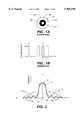
- FIG. 1Ais a plan view of an annular mask contact lens constructed in accordance with the prior art
- FIG. 1Bis a graph that illustrates the transmissivity of the lens of FIG. 1A;
- FIG. 2illustrates the point spread function of a point object imaged through a circular aperture
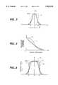
- FIG. 3illustrates the transmittance of a Gaussian apodized aperture in accordance with one embodiment of the present invention
- FIG. 4is a comparison of the perfect lens modulation transfer function of a uniform aperture and the modulation transfer function of a truncated Gaussian apodized aperture with respect to spatial frequency;
- FIG. 5is a comparison of the transmittance of a uniform aperture, Gaussian apodized aperture and pseudo-Gaussian apodized aperture;
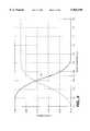
- FIG. 6is a graph of transmittance versus radial position for a pseudo-Gaussian apodized aperture in accordance with one embodiment of the present invention.
- FIG. 7is a graph of transmittance versus radial position for a pseudo-Gaussian apodized aperture in accordance with one embodiment of the present invention.
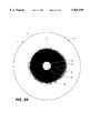
- FIG. 8is a rendition from a photograph of an annular mask in accordance with one embodiment of the present invention with the perimeter of the lens shown by a solid line;
- FIGS. 9A and 9Bare each a rendition from a photograph of an annular mask in accordance with another embodiment of the present invention with the perimeter of the lens shown by a solid line;
- FIG. 10is a graph of transmittance versus radial position for the annular mask of FIG. 9A;
- FIG. 11is one embodiment of a mask pattern used to produce the annular mask of FIG. 8;
- FIG. 12is a diagrammatic representation of an apparatus used to produce the annular mask of FIG. 8;
- FIG. 13is a diagrammatic representation of an apparatus used to produce the annular mask of FIGS. 9A and 9B;
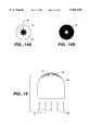
- FIGS. 14A AND 14Bare plan views of a set of masks used in the apparatus of FIG. 13;
- FIG. 15is an apparatus for use in another method for producing the present invention.
- FIGS. 16, 17, and 18illustrate a device that is particularly suited for producing lens that are offset.
- FIGS. 19A, 19B, 19C, and 19Ddepicts a device having a shutter system used to produce a mask on a lens.
- any vision correcting lensincluding but not limited to contact lenses (including rigid or hard lenses, hybrid lenses, hydrogel lenses and gel lenses that do or do not contain water), intraocular lenses, intracorneal lenses, and anterior chamber lenses.
- Suitable contact lens fabricated by this inventionare further described in U.S. patent application Ser. No. 08/663,622 entitled “Variable Transmissivity Annular Mask Lens For Treatment of Optical Aberrations” now U.S. Pat. No. 5,662,706 and Ser. No. 08/663,907, entitled “Annular Mask Lens Having Diffraction-Reducing Edges", both filed on Jun. 14, 1996 and which are incorporated herein.
- the annular mask 118 used in a conventional pinhole contact lens 110 (FIG. 1A) for presbyopic individualshas a sharp demarcation at the edge 132 of the clear central aperture 120.
- the graph in FIG. 1Billustrates that the lens body 112 has a transmissivity of 100% in the aperture 120 and in the annular region 117, and no light transmission through the opaque annular mask 118. It is known that the point spread function of a point object imaged through an optical system having a circular aperture (like a conventional pinhole contact lens) has a bright central area known as an Airy Disk 15 and several annuli lobes 13 of lower brightness as depicted in FIG. 2.
- the intensityis at a maximum at the center of the Airy Disk 15 and decreases to a first dark ring 36.
- the intensitythen increases and decreases infinitely radially outward with exponentially smaller and smaller peaks in the lobes 13. These cycles form several annuli peaks 37 and dark rings 38.
- the angular radius of the first dark ring 36 at the edge of the Airy Disk 15is defined by the wavelength of the light and the diameter of the circular aperture that the object is being imaged through.
- the maximum spatial frequency of an object that can be resolved by an optical system having a circular apertureis limited by the size of the Airy Disk 15 of the point spread function. In a contact lens, the maximum spatial frequency that is resolved is related to the visual acuity.
- the "side-lobes" or annuli lobes 13 of the point spread functionwill generally reduce the contrast (i.e., the modulation transfer function) of the image making it more difficult to discern detail. It is known that the "side-lobe" annuli 13 result from the diffraction of light as it passes the sharp edge 132 (i.e., abrupt demarcation) of the aperture 120. Therefore, eliminating or reducing the abrupt change eliminates or reduces the intensity of the "side-lobe" annuli which enhances the contrast of the image.
- the present inventionproduces a contact lens that utilizes a "soft edge" at the junction of the clear aperture and the annular mask. In one embodiment, this is accomplished by reducing the transmittance of the central aperture as a function of increasing radial position. In another embodiment, this is accomplished by decreasing the transmissivity of the annular mask as a function of increasing radial position.
- Apodizationis the process of changing the energy distribution of the point spread function by deliberate manipulation of the aperture function so as to improve image quality. In other words, the characteristics of the aperture are changed to improve the contrast.
- the present inventionutilizes amplitude apodization such that the amplitude transmittance aperture function varies from the center to the edge of the aperture.
- FIG. 3graphically illustrates this embodiment. The transmittance starts at 100% at the center of the lens and decreases as the radial position on the lens increases into the annular mask region.
- the transmittance function of the aperture 20 of lens 10(FIG.
- I(r)is the transmissivity amplitude for the aperture 20 as a function of the radial position
- ris the transmissivity amplitude for the aperture 20 as a function of the radial position
- cis the effective radius of the aperture (FIG. 3).
- the effective radiusis chosen from the range of radii of a conventional pinhole contact lens (typically about 0.25 to about 1.5 mm) so that the total energy transmitted through the apodized aperture is approximately equal to the total energy transmitted through a conventional pinhole aperture having a radius equal to the effective radius.
- cis 0.7 mm.
- Curve 2represents the transmissivity of a conventional pinhole contact lens.
- One advantage of the Gaussian apodized apertureis that it suppresses or even completely eliminates all of the side-lobe annuli 13 depending on the truncated width, D, of the Gaussian profile. The larger the truncated width, the greater the suppression of the side-lobe annuli.
- the truncated widthis the point at which the annular mask 15 (FIG. 8) begins to function effectively as opaque. Preferably, at a transmissivity of about 1% or less the annular mask is opaque.
- the side-lobe annuli of the point spread functionare greatly suppressed or eliminated compared to a uniform (or unapodized) conventional pinhole aperture, thus improving visual acuity.
- the width of the point spread function 51 (FIG. 2) for a truncated Gaussian apodizationis broader than that for a uniform aperture (i.e., Airy Disk) when the truncated width of the Gaussian apodization is at the effective width of the Gaussian profile and equal to the width of the uniform aperture.
- the contrast at low spatial frequencies for the truncated Gaussian apodized apertureis enhanced and suppressed at high spatial frequencies.
- the contrast at the high spatial frequencies for the truncated Gaussian apodized aperturecan be increased by truncating the Gaussian apodized profile at a larger width.
- the inventive methodproduces a lens with pseudo-Gaussian apodized (or tapered) amplitude transmittance varying toward the edge of the aperture.
- the apodized aperture functionis a pseudo-Gaussian profile 9 (FIG. 5) given by: ##EQU2## where I(r), r, and c are defined above and 2 ⁇ x ⁇ 10.
- FIGS. 5-7illustrate the effects of different values of x for the pseudo-Gaussian profile. For each of these figures, c equals 0.7 mm.
- the effective radiusis chosen from the range of radii of a conventional pinhole contact lens, as discussed above, which is typically in the range of about 0.25 to 1.5 mm.
- increasing values of xproduce a profile that is flatter in region 56 and steeper in region 58 than the Gaussian profile.
- FIGS. 6 and 7demonstrate the effects of pseudo-Gaussian profiles having different values for x.
- xequals 4 resulting in pseudo-Gaussian profile 60.
- the transmissivityis 100% until about 0.15 mm then gradually decreases to 20% transmissivity by about 0.79 mm and to 0% transmissivity by about 1.1 mm.
- xequals 10 resulting in pseudo-Gaussian profile 62.
- the transmissivityremains at 100% until about 0.4 mm, then steeply decreases to 20% transmissivity by about 0.75 mm and to 0% transmissivity by about 0.81 mm.
- the steep slope of profile 62more closely simulates a conventional pinhole aperture without having the attendant diffraction problems.
- xis selected to provide minimal diffraction for a given patient relative to that patient's visual characteristics at the time of fitting, such is within the skill in the art.
- the pseudo-Gaussian apodized aperturebecomes essentially a uniform aperture.
- the apodizationhas been described as a Gaussian or pseudo-Gaussian function, however, any number of functions can be used, such as, for example, linear, exponential, parabolic, combination thereof, to create the "soft edge.”
- the present inventionis not limited to "soft edges” that are defined by a mathematical function. It is within the scope of the invention that the "soft edge” be defined as any decreasing transmissivity that essentially begins at about 100% and decreases to about 20% or less within a distance in the range of about 0.05 mm or greater to about 1.0 mm or less, more preferably, decreases to about 10% or less within that distance, more preferably, decreases to about 1% or less within that distance.
- the "soft edge"surrounds a clear aperture of a defined diameter in the range of about 1.0 to 2.0 mm, more preferably about 1.5 mm.
- a contact lens 10that is fabricating by the present invention includes lens body 12 that has a first surface (not shown) optically configured (e.g., with a concave form) to conform to the eye curvature of the wearer.
- the lens body 12has a second surface 16 optically configured (e.g., with a convex form) to correct the vision of the wearer selectively at a focus between and including far and near objects. Focusing is achieved both by the lens 10 and by the refractive capability of the wearer's eye.
- the contact lenshas an annular mask 18 that is selectively transmissive along its inner edge 32 according to the principles discussed above to eliminate the sharp demarcation between the aperture 20 and the annular mask 18.
- the selective transmissivity along the inner edge 32is achieved by starting with about 100% transmissivity at the junction with the aperture 20 and reducing the transmissivity radially outward until the aperture functions essentially like a pinhole aperture (i.e., opaque) even though there is no sharp demarcation at the transition from the clear aperture to the opaque mask.
- the maskis opaque at a transmissivity of about 1% or less.
- the point at which the aperture functions essentially like a pinhole apertureis reached at a radial position of about 0.6 to 1 mm, more preferably about 0.6 to 0.8 mm, and most preferably at 0.7 mm.
- the transmissivitycan continue to decrease beyond the point at which the aperture functions essentially like a pinhole aperture until the mask becomes opaque or the transmissivity can change quickly to essentially opaque or opaque for the remainder of the width of the mask such that it blocks light energy at the lens body 12.
- the annular mask 18forms an essentially pinhole-like aperture 20 at the wearer's optical line-of-sight without diffraction effects generated by an abrupt edge.
- the variably transmissive aperture 20is preferably arranged to be concentric with the wearer's line of sight, which could be off-center with respect to the geometric center of the lens.
- the contact lens 10operates similar to a pinhole imager and increases the depth of focus for objects viewed by the wearer.
- the typical geometrical vision deficiencies encountered in wearerslike myopia, hyperopia, astigmatism, and presbyopia, spread out the light rays reaching the retina from a single object point in the field of view, thereby reducing image contrast.
- the variably transmissive aperture 20limits these light rays to a small bundle entering the eye pupil, and thereby improves image contrast.
- This lenshas the further advantage over a conventional pinhole lens in that the "soft edge" reduces or eliminates diffraction, thus producing better visual acuity for the wearer.
- the variably transmissive aperture 20is sized to provide pinhole-like imaging improvement for the wearer's vision deficiency.
- the variably transmissive aperture 20is smaller than the wearer's pupil size during average lighting conditions to improve vision clarity during such conditions.
- the variably transmissive aperture 20is smaller--or approximately equivalent to--the pupil of the wearer during bright light conditions. With this latter sizing, the wearer has improved vision clarity even during bright light conditions.
- the diameter of the variably transmissive aperture 20is generally about 1 mm or greater and 2 mm or less. In a preferred embodiment, the variably transmissive aperture 20 is approximately 1.5 mm in diameter.
- the lens 10is preferably fitted first, and the position of the pupil noted, and the lens 10 is then made to special order according to the fitting so the annulus 18 centers over the wearer's pupil.
- the lens 10can be mass-produced to meet a generalized population of wearer's or to meet a series of sets of wearer's requirements.
- the lens body 12is weighted (e.g., with a prism ballast) or shaped to center the variably transmissive aperture 20 at the optimal location on the eye of the wearer, and to reduce the movement of the contact 10 on the wearer's eye, preferably to less than approximately one and one-half mm. Accordingly, the lens 10 is held in a relatively constant position on the eye of the wearer, thereby maximizing the lens 10 for central vision while reducing the possibility of a reduction in the peripheral field by decentering and other excessive movements.
- the effective radius of the annular mask 18, from the soft edge 32 to the outside edge 26,is preferably approximately 0.65 mm or greater and 4.4 mm or less. This dimension is sized in the practice of the invention to accommodate the normal function of the human pupil.
- the lens body 12can be constructed with material to form a hard, gas permeable lens, or, alternatively, to form a soft contact lens (e.g., with a flexible soft polymer material). Combinations of these materials are also suitable to form a composite contact.
- the outer diameter of the lens body 12is approximately 7 to 18 mm, depending upon the wearer's eye size. It can be appreciated that the dimensions of the annular mask 18 can be adjusted for a particular wearer. For example, the annular mask 18 can be sized for a particular pupil, or further optimized for a desired visual correction.
- the surface 16 away from the wearer's eyeis appropriately configured and powered to correct the vision of the wearer for intermediate objects approximately midway between near and far objects.
- the contact lens 10typically corrects the wearer's vision by forming an optical correction on the surface 16.
- Common correctionsinclude convex, concave, toric, and astigmatic forms.
- the surface in contact with the wearer's eyecan similarly include an optical correction, such as a toric, astigmatic, or concave form.
- the portion of the surface 16 located in the variably transmissive aperture 20is configured to correct the wearer's vision at an intermediate focus, and the portion of surface 16 located within the region 17 corrects the wearer's vision for far objects to provide a multi-powered lens. It should be apparent to those skilled in the art that other multi-powered corrections are possible.
- the outer diameter of the annular mask 18can be sized to be smaller than a wearer's dilated pupil during lower light conditions. During lower light conditions, the wearer can thus receive light rays at the retina through the transmitting region 17. Accordingly, the contact lens 10 increasingly transmits more light rays as the wearer's pupil size increases or dilates. The wearer is, therefore, better able to discern the same objects which were viewed under brighter conditions.
- the mask region 18whether in the form of a coating or other structure, can have various selected levels of transmissivity. Opacity in the annular mask is generally desired for maximum visual sharpness. However, some wearers may want or need more light energy transmitted through the annular mask region 18 to avoid a sense of visual dimness or energy starvation (i.e., to attain more brightness) in medium to low light conditions. For example, the lens 10 (FIG. 9A) transmits less light energy towards the central portion 34 of the mask region 18 but still more than at the point of least transmissivity in the mask region and transmits relatively more light energy towards the outer edge 26 of the mask region than at the central portion 34 of the mask region 18.
- the transmissivity transition for the annular mask 18 from less light energy to more light energyutilizes the Gaussian and/or pseudo-Gaussian principles discussed above to eliminate any sharp demarcation between the outer edge 26 and the clear region 17 to avoid adverse diffraction effects.
- the transmissivity in the annular mask regioncan follow any mathematical function or not be defined by a mathematical function.
- FIG. 10illustrates the transmissivity for the lens of FIG. 9A. The transmissivity at the center of the lens starts at 100% then decreases according to the principles above until reaching a transmissivity below which the mask is opaque or performs as essentially opaque.
- the transmissivitystays at that level for a width of between about 0.5 mm to 4 mm, preferably about 1.5 to 2 mm, to take full advantage of the benefits of the pinhole effect, then increases in transmissivity to the outer "soft edge" 26 or to the edge of the lens.
- the transition in "soft edge” 32is more rapid than the transition in the annular mask to its outer portion.
- the tinted pattern on some conventional masked lenseshave a clear demarcation between the opaque zone and the partially opaque or transparent zones.
- the iris of the wearermay be dilated to a pupil size greater than the opaque ring. This can create an annular window for forming a "structural halo" which may be visually disturbing. This is believed to be due to the defocused light passing through the annulus of the partially opaque ring or passing around the outer edge of the opaque ring on a conventional masked lens.
- Lens fabrication by the present inventioneliminates the halo by diminishing the distinct demarcation between the opaque and the partially opaque zones or at the outer edge of the opaque ring by radially "tapering" the opacity of the tinted pattern (FIG. 9B).
- the lens body 12has a surface configured (e.g., with a concave form) to conform to the eye curvature of the wearer.
- the lens body 12has a second surface 16 with a convex form.
- the second surface 16can be optically configured to correct the vision of the wearer selectively at a focus between and including far and near objects.
- the present inventionis also applicable to non-pinhole contact lens as illustrated herein.
- the contact lens 10has an annular mask 18 of continuously variable transmissivity according to the particular needs of a given wearer.
- the annular mask 18is arranged to form an aperture 20 at the wearer's optical line-of-sight.
- the aperture 20is preferably arranged to be concentric with the wearer's pupil, which could be off-center with respect to the center of the lens body.
- the aperture 20is sized to reduce peripheral aberrations and distortions while maximizing retinal illumination. In other words, the aperture is sized to correct optical aberrations with minimal energy starvation to the retina.
- the apertureis typically of a size greater than conventional "pinhole" contact lenses which produce refractive correction by reducing the retinal blur circle to allow for simultaneous focus of near and distance vision. Therefore, the aperture of the lens is of sufficient size so as not to be effective as or a substitute for refractive correction.
- the diameter of the apertureis about 3.5 mm or larger, more preferably about 4 mm or larger, more preferably about 4.2 mm or larger for individuals having average sized pupils in medium light conditions.
- the size of the apertureis chosen to be as large as possible for a given wearer while still providing a mask region of sufficient size to treat the conditions described above.
- the aperture diametermay be about 2.0 mm or larger, preferably about 3.0 mm or larger, (which is within the range of conventional pinhole contact lens) but not be effective as or a substitute for refractive correction, such as for presbyopia.
- the mask region 18whether in the form of a coating or other structure, can have various selected levels of transmissivity. Opacity in the annular mask is generally desired for maximum visual sharpness as visual dimness or energy starvation is generally not a problem with the present invention because the aperture diameter is sized so large relative to the wearer's pupil. However, some wearers may want or need more light energy transmitted through the annular mask region 18 to avoid a sense of visual dimness (i.e., to attain more brightness) in medium to low light conditions. For example, the lens 10 (FIG. 9B) transmits less light energy towards the central portion 34 of the mask region 18 and transmits relatively more light energy towards the outer edge 26 of the mask region.
- the transmissivity transition for the annular mask 18 from less light energy to more light energyutilizes a Gaussian and/or pseudo-Gaussian function to eliminate any sharp demarcation at the edge of the mask region or between the outer edge 26 and any clear region that may exist if the mask region does not extend all the way to the outer region of the lens to avoid the adverse diffraction effects.
- the transmissivity in the annular mask regioncan follow any predetermined mathematical function or not be defined by a mathematical function.
- the tapered (progressive) mask patternhas a clear central aperture and the transmissivity of the mask increases gradually from 0% transmissivity at the edge of the clear central aperture to the periphery of the mask.
- the variation in transmissivityis symmetrical to the axis through the center of the aperture.
- the aperture 20typically is greater than the diameter at which diffraction effects start to degrade image quality.
- the benefits achievedcan be destroyed by diffraction if small apertures relative to pupil size are incorporated into the lens.
- Such small apertures that have these adverse resultsinclude radial slits and scalloped patterns. Diffraction can actually increase the blurring of the retinal image such that the wearer's vision is degraded rather than improved.
- the lower limit of an aperture in a usable contact lensis above about 3.5 mm, more preferably above about 4.0 mm, more preferably above about 4.2 mm.
- the inventionalso produces a "soft edge" 32 at the junction of the clear aperture 20 and the annular mask 18. This can be accomplished by either reducing the transmittance of the central aperture as a function of increasing radial position, or by decreasing the transmissivity of the annular mask as a function of increasing radial position.
- the inventive processeliminates the sharp edge (i.e., abrupt demarcation) by apodizing the aperture.
- the transmittance function of the aperture 20 on lens 10can be a Gaussian apodized aperture or pseudo-Gaussian apodized aperture described again by: ##EQU3## where I(r) is the transmissivity amplitude for the aperture 20 as a function of the radial position, r, and c is the effective radius of the aperture.
- the effective radiusis of sufficient size to reduce peripheral aberrations and distortions but not to be effective as or a substitute for refractive correction.
- the effective radiusis in the range from about 2.0 to about 4.2 mm, and more preferably in the range from about 3.5 to about 4.0 mm, and x is chosen from the range 2 ⁇ x ⁇ 5.
- the effective radiusis chosen for a particular patient based on the type of optical distortion and the location of that distortion. For example, corneal topography can be utilized to identify the location and severity of keratoconus. Then, c would be chosen based on that location.
- the functionis referred to as Gaussian when x equals 2 and as pseudo-Gaussian for values greater than 2 and preferably no more than 10.
- any number of functionscan be used to describe the apodization of the aperature of the lens in FIG. 9B.
- the present inventionis not limited to "soft edges" that are defined by a mathematical function. It is within the scope of the invention that the "soft edge" be defined as any decreasing transmissivity that has diffraction-reducing effect as noted above.
- the transmissivity at the center of the lensstarts at 100% then decreases according to the principles above until reaching a transmissivity below which the mask is opaque or performs as essentially opaque.
- the transmissivitystays at that level for a width of between about 1 mm to about 4 mm, preferably about 1.5 to 2 mm, then increase in transmissivity to the outer "soft edge" 26 or to the edge of the lens.
- the transition in "soft edge” 32is more rapid than the transition through central portion 34 in the annular mask to its outer portion 26.
- An optimal tapering profile of the opaque maskwill be related to the pupil sizes and the retinal illumination required for the wearer. Since the lens may not always center over the wearer's pupil, the lens 10 is preferably fitted first, and the position of the annulus 18 noted, and the lens 10 then made to special order according to the fitting so the annulus 18 centers over the wearer's pupil. Alternatively, the lens can be mass-produced to fit a generalized population of wearers or to fit several sets of generalized wearers.
- the lens body 12is weighted (e.g., with a prism ballast) or shaped to center the aperture 20 at the optimal location on the eye of the wearer, and to reduce the movement of the contact 10 on the wearer's eye, preferably to less than approximately one and one-half mm. Accordingly, the lens 10 is held in a relatively constant position on the eye of the wearer, thereby maximizing the lens 10 for central vision while reducing the possibility of a reduction in the peripheral field by decentering and other excessive movements.
- the radial width of the annular mask 18, from the inside edge 32 to the outside edge 26,is preferably between about 0.95 mm or greater and about 4.5 mm or less. It will be appreciated that the annular mask can extend to the outside edge of the lens and thus its width would be determined by the diameter of the lens.
- the radial widthis sized in the practice of the invention to accommodate the normal function of the human pupil while being effective in treating the above-listed conditions.
- the mask regions having variable transmissivity on the lenscan be constructed in several ways.
- the inventive methodsare applicable for fabricating "pinhole” and non-pinhole contact lenses. It is understood in describing the methods herein, the inventive techniques are not limited to the fabrication of any specific lens that is used for illustrative purposes.
- an opaque spinning mask 44(FIG. 11) is employed in the device illustrated diagrammatically in FIG. 12 to produce the annular mask shown in FIG. 8.
- This methodcan be used to produce a variably transmissive annular mask of any desirable profile depending on the pattern of the spinning mask used.
- a light source 40 and condenser lens 42provide back illumination to mask 44 which is spun by motor 46.
- the spinning mask 44 as an objectis imaged through relay lens 48 and imaging lens 50 onto the lens 10 using a photo-reactive dye or coating in or on the lens.
- Preferred photo-reactive dyesdegrade upon exposure to radiation thereby permitting radiation visible (e.g., visible light) to transmit through a portion of the lens that was hitherto opaque.
- the opaque mask 44has a central light transmitting region 52 and several light transmitting "petals” 54 extending radially outward from the region 52.
- the profile of the variably transmissive annular mask on the resulting lensis controlled by changing the shape of the design of the "petals". As the mask is spinning about an axis symmetric to the petal pattern, the image of the spinning mask becomes an apodized pattern on the lens with continuously variable gray tones.
- Suitable photo-reactive dyesare known and are described, for instance, in GB 1,547,525 which is incorporated herein.
- a beamsplitter 60as illustrated diagrammatically in FIG. 13, to combine the apodized aperture pattern with a second spinning mask 62 of any desirable pattern using another projection system branch.
- the beamsplittercan be, for example, a one-half silvered mirror.
- a tapered (i.e., reverse apodized) annular mask patternis implemented in the second branch of the projection system to produce a masked lens as shown in FIGS. 9A and 9B having diffraction-reducing edges on the inside of the annular mask and the outside of the annular mask.
- a mask 64 with a plurality of opaque petals 66 on a light-transmitting substrate disk 68(FIG. 14A) is illuminated by a light source 70 and condenser lens 72 (FIG. 13).
- a magnified or demagnified image of the mask 64is formed on the lens 10 by relay and imaging lenses 74, 76.
- the image of the spinning maskbecomes a brightness-tapered pattern with continuous gray tones.
- the brightness tapered profile of the imageis controlled by the design of the shape of the petals.
- a second mask 62 of any desirable pattern, such as shown in FIG. 14B,is illuminated by a second light source 80 and condenser lens 82.
- a second magnified or demagnified imageis formed on the lens 10 by relay and imaging lenses 84, 76 and beamsplitter 60.
- the final imageis a combined image of the individual images superimposed on the lens 10.
- a transparent dome 86(FIG. 15) having a light-occluding portion 88 is used to produce the annular mask pattern in the lens.
- the dome (or support) 86has a groove machined into the top of the dome beginning at a depth of about 0.1 mm deep in the region surrounding an area not machined out that will form the central aperture on the lens and rapidly increasing to a depth of about 1 mm at a diameter of about 1.6 mm then gradually decreasing to a depth of 0.1 mm at an outside diameter of 5.5 mm.
- the grooveis filled with black blocking wax to form light occluding portion 88.
- lens 10that has been emersed in a diazo dye solution (HD-61) and is placed on the dome 86 in position so that the light-occluding portion of the dome is in the position where the resulting annular mask should be on the finished lens.
- Light 90is shone from beneath the dome until all exposed areas of the lens become discolored. The degree of discoloration at any point in the lens is proportional to the amount of radiation exposed thereto.
- a typical light sourceis a HA 6000 halogen ELH or ENX lamp.
- the lensis then placed into phloroglucinol solution in which the areas of the lens corresponding to the light-occluding part of the dome turn black and form a continually variable shade of gray resulting in an annular mask pattern such as shown in FIG. 9A.
- the lens 10is positioned on an opaque dome 92 in housing 98, and then contacted with a dam ring 94 to hold dye solution 96 (FIG. 16).
- Dye solutionis placed in the dam ring and allowed to permeate the lens from the top side of the lens only. Dye is allowed to diffuse into the lens only to a depth necessary to produce the desired intensity, and not all the way through the thinnest section of the lens.
- the dam ringis removed and the dye rinsed off the surface quickly with water.
- a light restricting mask 100is then placed over the lens 10 and the dye in the lens is desensitized by exposure to light (FIG. 17).
- the mask 100is produced on a computer monitor with a commercially available graphics program.
- the mask 100can be produced by methods such as but not limited to selection of appropriate neutral density or color filters, metal deposition such as sputtering, vacuum deposition, printing, spraying, etc.
- the maskcan be raised slightly above the lens, so that a diffused edge will form from light diffracting effects.
- the distance of the mask from the lensBy varying the distance of the mask from the lens, the light intensity, duration of exposure to the light, and quality of light in the lens, different tapering effects may be produced in the lens.
- the device of FIGS. 16 and 17can be employed to fabricated contact lens that has a circular central portion which is offset from the geometric center of the lens itself.
- One reason for the offsetis that for most individuals, after the contacts lens has been placed on the cornea, movement of the contact lens causes the actual visual axis through the cornea to not coincide with the geometric axis of the lens. Offsetting compensates for this phenomenon so that the visual axis and geometric axis are aligned.
- the center of the central portionis offset a distance of about 0 mm to 1.5 mm. The requisite distance for an individual can be measured by conventional techniques prior to fabrication of the lens.
- FIG. 18depicts a device that is similar to the one illustrated in FIGS. 16 and 17 which is particularly suited for fabricating contact lens with a central portion which is offset from the geometric center of the contact lens.
- the devicesincludes a center dam 200, an inner ring 210, and an outer ring 220.
- the center damhas a diameter which is substantially equal to that of the pupil.
- a lensis positioned on the surface of dome 92 in housing 98. Thereafter, the center dam and the inner ring are placed in contact with the surface of the lens.
- a solution containing a vat dye in its leuco solubilized formis placed in contact with the surface of the lens that is bordered by the center dam and the inner ring.
- the inner ringis lifted from the surface of the lens so that the vat dye solution now is in contact with a larger area of the lens surface that is bordered by the center dam and outer ring. In this fashion, more vat dye diffuses into the lens surface in the area adjacent to the center dam than in the area on the lens surface that is exposed upon lifting of the inner ring. Subsequently, the solution is removed and the lens is placed into a solution of sodium nitrite in dilute sulfuric acid whereupon the dye will precipitate out into the lens. The lens now contains a permanent dark color ring having a soft edge and the lens has a substantially clear center portion that is offset from the geometric center of the lens. Suitable vat dyes are described for example, in U.S. Pat. Nos. 4,898,695 and 5,534,038, which are incorporated herein.
- FIGS. 19A, 19B, 19C, and 19DAnother technique employs a shutter-like mechanical device with several shutter blades arranged to provide masking in three concentric annular regions corresponding to the inner soft edge, the opaque portion and the outer soft edge as depicted in FIGS. 19A, 19B, 19C, and 19D.
- lens 158that had been emersed in a diazo dye solution, is covered by a shutter system having a plurality of blades 125 (not all of which are shown) which initially blocks the passage of light onto the annular region defined by rings 151 and 154.
- the shutteropens gradually as shown in FIGS. 19B and 19C until the shutter is in the opened position as shown in FIG. 19D.
- the lens region bordered by rings 152 and 153remained covered and is not exposed to any radiation whereas the regions defined by rings 153 and 154 and by rings 151 and 152 are exposed to varying amounts of radiation.
- the regions on the lens that are exposedwill discolor in proportion to the amount of radiation received.
- the regions corresponding to the light-occluding partwill turn black whereas the other regions will be clear or have variable levels of transparency.
- regions A and Ewill be substantially clear
- regions B and Dwill exhibit a gradient in the levels of transparency
- region Cwill be substantially opaque.
- the opaque regionwill preferably have 1% transmissivity or less.
- the transmissivity of the inner soft edge and the outer soft edgecan be varied, in part, by the speed of the shutter blades opening and with the shape of the shutter blades.
- this techniquecan also be employed wherein the shutter blades are initially in the opened position and then gradually closed.
- the sequence of exposing the dye to radiation and of opening and/or closing the shuttercan be varied to generate different patterns of transmissivity in the contact lens. For instance, one portion of the shutter may be opening while another portion is simultaneously being closed.
- a contact lens constructed in accordance with the inventionis colored, tinted, or otherwise shaded, when appropriate, by methods known in the art.
- This coloring or tintingcan be cosmetic, as it often is for many wearers of common contact lenses. It can also reduce the sometimes objectionable appearance of the annular mask 18 when viewed on the eye of the wearer.
- the inventionprovides for an annulus that is matched to the wearer's iris. It also provides for an annulus that enhances or changes the appearance of the wearer's iris, if desired.
- a further enhancementcan include a limbal ring as described in U.S. Pat. No. 5,302,978 which is incorporated herein.
- the concentration of the dyes usedcan be varied (e.g., diluted) to achieve the desired degree of opaqueness and other related features.
- the arrangement and size of the annular mask 18,can be selected for a particular wearer to optimize the visual correction available.
- the contact lens body 12can be constructed with a yellow appearance, giving the wearer a physiological impression of brighter lighting.
- the inventioncan also aid wearers suffering from other vision deficiencies and disorders.
- a contact lens in accordance with FIG. 9was produced with the following procedure.
- a 1% sensitizer solutionwas formed by dissolving 1.0 grams of 4-diazo-[4'-toluyl]-mercapto-2,5-diethoxybenzene zinc chloride (also referred to as Diazo-15 or HD-61) in 100.0 grams of de-ionized water and sonicating for 15 to 20 minutes.
- a 1% developer solutionwas formed by dissolving 1.0 grams of phloroglucinol dihydrate in 100.0 grams of de-ionized water and sonicating for 15-20 minutes. The solutions were filtered using 0.45 micron filter paper prior to use. Prior to tinting, the lens was equilibrated in water for at least 1 hour.
- the lenswas then pat dry and dropped in a vial containing about 6-8 mm of sensitizer.
- the front curve of the lenswas uppermost.
- the lenswas left in the solution for 3 minutes.
- the lenswas removed, rinsed with water and pat dry.
- the lenswas positioned on a dome and the imaging mask pattern placed over the lens on the dome.
- the domewas then placed over a type ENX HA 6000 Halogen light source for 2 minutes.
- the lenswas then removed from the dome and placed in the developer solution for 2 minutes.
- the lenswas then rinsed with clean water and processed via the usual extraction and hydration processes.
Landscapes
- Health & Medical Sciences (AREA)
- Ophthalmology & Optometry (AREA)
- Physics & Mathematics (AREA)
- Engineering & Computer Science (AREA)
- General Health & Medical Sciences (AREA)
- General Physics & Mathematics (AREA)
- Animal Behavior & Ethology (AREA)
- Veterinary Medicine (AREA)
- Vascular Medicine (AREA)
- Life Sciences & Earth Sciences (AREA)
- Biomedical Technology (AREA)
- Transplantation (AREA)
- Public Health (AREA)
- Heart & Thoracic Surgery (AREA)
- Optics & Photonics (AREA)
- Cardiology (AREA)
- Oral & Maxillofacial Surgery (AREA)
- Mechanical Engineering (AREA)
- Manufacturing & Machinery (AREA)
- Mathematical Physics (AREA)
- Eyeglasses (AREA)
Abstract
Description
Claims (19)
Priority Applications (3)
| Application Number | Priority Date | Filing Date | Title |
|---|---|---|---|
| US08/761,308US5965330A (en) | 1996-12-06 | 1996-12-06 | Methods for fabricating annular mask lens having diffraction-reducing edges |
| PCT/US1997/020354WO1998025180A1 (en) | 1996-12-06 | 1997-11-20 | Methods for fabricating annular mask lens having diffraction-reducing edges |
| AU54313/98AAU5431398A (en) | 1996-12-06 | 1997-11-20 | Methods for fabricating annular mask lens having diffraction-reducing edges |
Applications Claiming Priority (1)
| Application Number | Priority Date | Filing Date | Title |
|---|---|---|---|
| US08/761,308US5965330A (en) | 1996-12-06 | 1996-12-06 | Methods for fabricating annular mask lens having diffraction-reducing edges |
Publications (1)
| Publication Number | Publication Date |
|---|---|
| US5965330Atrue US5965330A (en) | 1999-10-12 |
Family
ID=25061843
Family Applications (1)
| Application Number | Title | Priority Date | Filing Date |
|---|---|---|---|
| US08/761,308Expired - LifetimeUS5965330A (en) | 1996-12-06 | 1996-12-06 | Methods for fabricating annular mask lens having diffraction-reducing edges |
Country Status (3)
| Country | Link |
|---|---|
| US (1) | US5965330A (en) |
| AU (1) | AU5431398A (en) |
| WO (1) | WO1998025180A1 (en) |
Cited By (69)
| Publication number | Priority date | Publication date | Assignee | Title |
|---|---|---|---|---|
| US6554424B1 (en) | 1999-03-01 | 2003-04-29 | Boston Innovative Optices, Inc. | System and method for increasing the depth of focus of the human eye |
| WO2002083033A3 (en)* | 2001-04-17 | 2003-08-21 | Univ Vanderbilt | Intraocular lens system |
| US20030225455A1 (en)* | 2000-09-15 | 2003-12-04 | Cathey Wade Thomas | Extended depth of field optics for human vision |
| US20040046931A1 (en)* | 2002-09-06 | 2004-03-11 | Jerome Legerton | Hybrid contact lens system and method |
| US20040158322A1 (en)* | 2002-04-17 | 2004-08-12 | Shen Jin Hui | Intraocular lens system |
| US20040179167A1 (en)* | 2002-09-06 | 2004-09-16 | Ali Dahi | Hybrid contact lens system and method |
| US20050046794A1 (en)* | 2003-06-17 | 2005-03-03 | Silvestrini Thomas A. | Method and apparatus for aligning a mask with the visual axis of an eye |
| US6923540B2 (en) | 2002-07-31 | 2005-08-02 | Novartis Ag | Toric multifocal contact lenses |
| US20050168790A1 (en)* | 2004-01-29 | 2005-08-04 | Asml Holding N.V. | System and method for calibrating a spatial light modulator |
| US7018039B2 (en) | 2003-11-14 | 2006-03-28 | Synergeyes,Inc. | Contact lens |
| US20060116764A1 (en)* | 2004-12-01 | 2006-06-01 | Simpson Michael J | Apodized aspheric diffractive lenses |
| US20060113054A1 (en)* | 2004-12-01 | 2006-06-01 | Silvestrini Thomas A | Method of making an ocular implant |
| US20060118263A1 (en)* | 2004-12-01 | 2006-06-08 | Silvestrini Thomas A | Method of making an ocular implant |
| US7061693B2 (en) | 2004-08-16 | 2006-06-13 | Xceed Imaging Ltd. | Optical method and system for extended depth of focus |
| US20060184243A1 (en)* | 2004-10-22 | 2006-08-17 | Omer Yilmaz | System and method for aligning an optic with an axis of an eye |
| US7104648B2 (en) | 2002-09-06 | 2006-09-12 | Synergeyes, Inc. | Hybrid contact lens system and method |
| US20060235428A1 (en)* | 2005-04-14 | 2006-10-19 | Silvestrini Thomas A | Ocular inlay with locator |
| US20060238713A1 (en)* | 2002-09-06 | 2006-10-26 | Ali Dahi | Hybrid contact lens system and method |
| US20060250576A1 (en)* | 2005-05-06 | 2006-11-09 | Legerton Jerome A | Hybrid contact lens system and method of fitting |
| US20060265058A1 (en)* | 2005-04-14 | 2006-11-23 | Silvestrini Thomas A | Corneal mask formed of degradation resistant polymer and providing reduced corneal deposits |
| US20070082563A1 (en)* | 2005-10-11 | 2007-04-12 | Jerome Legerton | Hybrid contact lens system and method of fitting |
| US20070236769A1 (en)* | 2004-08-16 | 2007-10-11 | Xceed Imaging Ltd. | Optical method and system for extended depth of focus |
| US20070258071A1 (en)* | 2001-10-30 | 2007-11-08 | Pixelligent Technologies Llc | Advanced exposure techniques for programmable lithography |
| US20070273825A1 (en)* | 2006-05-25 | 2007-11-29 | Jerome Legerton | Hybrid contact lens system and method of fitting |
| EP1278451A4 (en)* | 2000-04-28 | 2007-12-19 | Univ Rochester | Improving vision and retinal imaging |
| US20080074611A1 (en)* | 2006-09-22 | 2008-03-27 | Meyers William E | Hybrid contact lens with improved resistance to flexure and method for designing the same |
| US20090175525A1 (en)* | 2008-01-08 | 2009-07-09 | Amo Wavefront Sciences Llc | Systems and Methods for Measuring Surface Shape |
| US20090174096A1 (en)* | 2007-10-25 | 2009-07-09 | Wei Yi Hsu | Polarized Lens and Method of Making Polarized Lens |
| US7628810B2 (en) | 2003-05-28 | 2009-12-08 | Acufocus, Inc. | Mask configured to maintain nutrient transport without producing visible diffraction patterns |
| US20090306773A1 (en)* | 2008-06-04 | 2009-12-10 | Acufocus, Inc. | Opaque corneal insert for refractive correction |
| US20100073631A1 (en)* | 2008-09-22 | 2010-03-25 | Dretzke Debra A | Device and method for reducing visual aberration |
| US20100082100A1 (en)* | 2008-09-30 | 2010-04-01 | Yoichi Mikawa | Intraocular lens |
| US7828432B2 (en) | 2007-05-25 | 2010-11-09 | Synergeyes, Inc. | Hybrid contact lenses prepared with expansion controlled polymeric materials |
| WO2011020078A1 (en) | 2009-08-13 | 2011-02-17 | Acufocus, Inc. | Masked intraocular implants and lenses |
| US20110194195A1 (en)* | 2010-02-09 | 2011-08-11 | Zeev Zalevsky | Optical apparatus with structure for liquid invariant performance |
| JP2011177599A (en)* | 2008-09-30 | 2011-09-15 | Yoichi Mikawa | Intraocular lens |
| USD656526S1 (en) | 2009-11-10 | 2012-03-27 | Acufocus, Inc. | Ocular mask |
| WO2013048991A1 (en)* | 2011-09-30 | 2013-04-04 | Johnson & Johnson Vision Care, Inc. | Method of creating a visible mark on lens using a leuco dye |
| WO2013123265A1 (en) | 2012-02-16 | 2013-08-22 | Acufocus, Inc. | Masked ocular device for implantation adjacent to an intraocular lens |
| WO2014074610A1 (en) | 2012-11-09 | 2014-05-15 | Acufocus, Inc. | Process for manufacturing an intraocular lens |
| US8734033B2 (en) | 2012-03-27 | 2014-05-27 | Ppg Industries Ohio, Inc. | Optical mechanism with indexing stage with at least one fixed diameter apodized aperture and method of making same |
| JP2014160258A (en)* | 2014-03-25 | 2014-09-04 | Hikoyuki Konno | Contact lens with function |
| WO2014158653A1 (en) | 2013-03-14 | 2014-10-02 | Acufocus, Inc. | Process for manufacturing an intraocular lens with an embedded mask |
| WO2014164056A1 (en) | 2013-03-13 | 2014-10-09 | Acufocus, Inc. | In situ adjustable optical mask |
| JP5675915B1 (en)* | 2013-08-30 | 2015-02-25 | 株式会社シード | Colored contact lens manufacturing method and jig therefor |
| US9195074B2 (en) | 2012-04-05 | 2015-11-24 | Brien Holden Vision Institute | Lenses, devices and methods for ocular refractive error |
| US9201250B2 (en) | 2012-10-17 | 2015-12-01 | Brien Holden Vision Institute | Lenses, devices, methods and systems for refractive error |
| US9329407B2 (en) | 2010-09-13 | 2016-05-03 | The Regents Of The University Of Colorado, A Body Corporate | Extended depth field optics with variable pupil diameter |
| WO2016081493A1 (en) | 2014-11-19 | 2016-05-26 | Acufocus, Inc. | Fracturable mask for treating presbyopia |
| US9427311B2 (en) | 2009-08-13 | 2016-08-30 | Acufocus, Inc. | Corneal inlay with nutrient transport structures |
| US20160306184A1 (en)* | 2013-12-20 | 2016-10-20 | Sony Corporation | Apparatus and optical system including an optical element |
| US9541773B2 (en) | 2012-10-17 | 2017-01-10 | Brien Holden Vision Institute | Lenses, devices, methods and systems for refractive error |
| US9545303B2 (en) | 2011-12-02 | 2017-01-17 | Acufocus, Inc. | Ocular mask having selective spectral transmission |
| USD778976S1 (en)* | 2011-09-07 | 2017-02-14 | Hikoyuki Konno | Contact lens |
| WO2017062316A1 (en) | 2015-10-05 | 2017-04-13 | Acufocus, Inc. | Methods of molding intraocular lenses |
| WO2017091520A1 (en) | 2015-11-24 | 2017-06-01 | Acufocus, Inc. | Toric small aperture intraocular lens with extended depth of focus |
| WO2017196823A1 (en)* | 2016-05-09 | 2017-11-16 | Trustees Of Boston University | Method and system for enhanced single particle reflectance imaging |
| US20170343893A1 (en)* | 2016-05-25 | 2017-11-30 | U.S.A. As Represented By The Administrator Of The National Aeronautics And Space Administration | Design and fabrication of partially transparent petaled mask or occulter using grayscale lithography |
| CN107643557A (en)* | 2016-07-21 | 2018-01-30 | 擎中科技(上海)有限公司 | A kind of preparation method of optical grating construction, 3 d display device and optical grating construction |
| US10004593B2 (en) | 2009-08-13 | 2018-06-26 | Acufocus, Inc. | Intraocular lens with elastic mask |
| US10330939B1 (en)* | 2017-12-20 | 2019-06-25 | Aperture In Motion, LLC | Light control devices and methods for regional variation of visual information and sampling |
| US10768431B2 (en) | 2017-12-20 | 2020-09-08 | Aperture In Motion, LLC | Light control devices and methods for regional variation of visual information and sampling |
| US10765510B2 (en) | 2015-04-14 | 2020-09-08 | Z Optics, Inc. | High definition and extended depth of field intraocular lens |
| WO2021174289A1 (en)* | 2020-03-01 | 2021-09-10 | Nthalmic Holding Pty Ltd | Contact lens apparatus for myopia management |
| US11364110B2 (en) | 2018-05-09 | 2022-06-21 | Acufocus, Inc. | Intraocular implant with removable optic |
| WO2022254389A1 (en)* | 2021-06-03 | 2022-12-08 | Brien Holden Vision Institute Limited | Ophthalmic lenses utilizing binary amplitude modulation |
| US11547554B2 (en) | 2015-04-14 | 2023-01-10 | Z Optics, Inc. | High definition and extended depth of field intraocular lens |
| US11579240B2 (en) | 2016-08-22 | 2023-02-14 | The University Of Sussex | Attitude determination system |
| WO2025048730A1 (en)* | 2023-08-31 | 2025-03-06 | Vsy Biyoteknoloji Ve Ilac Sanayi Anonim Sirketi | Ophthalmic lens with central obscuration |
Families Citing this family (12)
| Publication number | Priority date | Publication date | Assignee | Title |
|---|---|---|---|---|
| US7267846B2 (en) | 1999-11-01 | 2007-09-11 | Praful Doshi | Tinted lenses and methods of manufacture |
| US6880932B2 (en) | 1999-11-01 | 2005-04-19 | Praful Doshi | Tinted lenses and methods of manufacture |
| AU782256B2 (en)* | 1999-11-01 | 2005-07-14 | Praful Doshi | Tinted lenses and methods of manufacture |
| JP4896737B2 (en) | 2003-12-29 | 2012-03-14 | アボット・メディカル・オプティクス・インコーポレイテッド | Intraocular lens with visible light selective transmission region |
| US7278737B2 (en) | 2004-04-30 | 2007-10-09 | Advanced Medical Optics, Inc. | Ophthalmic devices having a highly selective violet light transmissive filter and related methods |
| AU2005309835B2 (en) | 2004-11-22 | 2011-08-04 | Johnson & Johnson Surgical Vision, Inc. | Copolymerizable azo compounds and articles containing them |
| AU2005309912B2 (en) | 2004-11-22 | 2011-10-06 | Johnson & Johnson Surgical Vision, Inc. | Copolymerizable methine and anthraquinone compounds and articles containing them |
| DE102007015599A1 (en)* | 2007-03-29 | 2008-10-02 | Daimler Ag | Avoiding halos around intense light sources in optical systems, especially in night vision systems |
| US8317322B2 (en) | 2010-02-04 | 2012-11-27 | Johnson & Johnson Vision Care, Inc. | Contact lens with brightly colored sclera |
| RU2562696C2 (en)* | 2011-04-18 | 2015-09-10 | Джонсон Энд Джонсон Вижн Кэа, Инк. | Contact lenses with vividly coloured portion positioned on sclera |
| ES2686472T3 (en)* | 2015-03-10 | 2018-10-18 | Consejo Superior De Investigaciones Científicas | Photochemically induced coupling of intraocular implants |
| US10838234B2 (en)* | 2016-08-18 | 2020-11-17 | Johnson & Johnson Vision Care, Inc. | Contact lens with improved visual performance and minimized halo utilizing pupil apodization |
Citations (28)
| Publication number | Priority date | Publication date | Assignee | Title |
|---|---|---|---|---|
| FR1115140A (en)* | 1954-11-27 | 1956-04-19 | Contact lens improvement | |
| FR1400566A (en)* | 1964-04-17 | 1965-05-28 | Method and device for selecting, adjusting and centering ophthalmic lenses | |
| US3339997A (en)* | 1962-07-30 | 1967-09-05 | Plastic Contact Lens Company | Bifocal ophthalmic lens having different color distance and near vision zones |
| GB1276003A (en)* | 1969-03-10 | 1972-06-01 | Frank Auld | Corneal contact device |
| US3946982A (en)* | 1974-09-03 | 1976-03-30 | Textron, Inc. | Adjustable mold for direct casting of plastic multifocal lenses |
| GB1547525A (en)* | 1976-08-02 | 1979-06-20 | Meshel L G | Selective colouring of soft contact lenses |
| US4666249A (en)* | 1985-08-14 | 1987-05-19 | Sola U.S.A. Inc. | Surface-treated contact lens and method of producing |
| US4672021A (en)* | 1985-06-03 | 1987-06-09 | Fairmount Chemical Company | Contrast enhancement layer composition with naphthoquinone diazide, indicator dye and polymeric binder |
| EP0225098A2 (en)* | 1985-11-19 | 1987-06-10 | University Optical Products Co | Bifocal lens |
| US4702574A (en)* | 1985-10-15 | 1987-10-27 | Bausch & Lomb Incorporated | Contact lenses having fluorescent colorants and apparatus for making such lenses |
| FR2599156A1 (en)* | 1986-05-20 | 1987-11-27 | Guyot Bernard | Fixed iris correcting short-sighted and long-sighted vision |
| US4849323A (en)* | 1986-08-12 | 1989-07-18 | Matsushita Electric Industrial Co., Ltd. | Pattern forming method using contrast enhanced material |
| US4889795A (en)* | 1987-02-23 | 1989-12-26 | Oki Electric Industry Co., Ltd. | Process for forming photoresist pattern using contrast enhancement layer with abietic acid |
| JPH031857A (en)* | 1989-05-31 | 1991-01-08 | New Eeji:Kk | Visual power correcting instrument |
| US4994080A (en)* | 1988-07-15 | 1991-02-19 | Shepard Dennis D | Optical lens having at least one stenopaeic opening located in the central area thereof |
| US5089024A (en)* | 1988-04-19 | 1992-02-18 | Storz Instrument Company | Multi-focal intraocular lens |
| US5108169A (en)* | 1991-02-22 | 1992-04-28 | Mandell Robert B | Contact lens bifocal with switch |
| US5172143A (en)* | 1990-01-22 | 1992-12-15 | Essilor International Cie Generale D'optique | Artificial optical lens and method of manufacturing it |
| US5260727A (en)* | 1990-10-22 | 1993-11-09 | Oksman Henry C | Wide depth of focus intraocular and contact lenses |
| US5296305A (en)* | 1990-05-11 | 1994-03-22 | Esslior International (Compagnie Generale D'optique) | Method of fabricating a lens made of transparent polymer with modulated refracting index |
| US5302978A (en)* | 1990-10-30 | 1994-04-12 | Pilkington Visioncare, Inc. | Contact lens |
| WO1994023327A1 (en)* | 1993-03-27 | 1994-10-13 | Pilkington Barnes Hind, Inc. | Contact lens designed to accommodate and correct for the effects of presbyopia |
| JPH0750242A (en)* | 1993-08-05 | 1995-02-21 | Hitachi Ltd | Optical transfer drawing device |
| US5414477A (en)* | 1989-11-01 | 1995-05-09 | Wesley-Jessen Corporation | Colored contact lens having very natural appearance |
| US5516467A (en)* | 1993-07-16 | 1996-05-14 | Menicon Co., Ltd. | Process for producing a tinted contact lens |
| US5643249A (en)* | 1992-02-14 | 1997-07-01 | Nidek Co., Ltd. | Optical ophthalmic treatment apparatus |
| US5662706A (en)* | 1996-06-14 | 1997-09-02 | Pbh, Inc. | Variable transmissivity annular mask lens for the treatment of optical aberrations |
| WO1997048004A1 (en)* | 1996-06-14 | 1997-12-18 | Pbh, Inc. | Annular mask lens having diffraction-reducing edges |
- 1996
- 1996-12-06USUS08/761,308patent/US5965330A/ennot_activeExpired - Lifetime
- 1997
- 1997-11-20WOPCT/US1997/020354patent/WO1998025180A1/enactiveApplication Filing
- 1997-11-20AUAU54313/98Apatent/AU5431398A/ennot_activeAbandoned
Patent Citations (28)
| Publication number | Priority date | Publication date | Assignee | Title |
|---|---|---|---|---|
| FR1115140A (en)* | 1954-11-27 | 1956-04-19 | Contact lens improvement | |
| US3339997A (en)* | 1962-07-30 | 1967-09-05 | Plastic Contact Lens Company | Bifocal ophthalmic lens having different color distance and near vision zones |
| FR1400566A (en)* | 1964-04-17 | 1965-05-28 | Method and device for selecting, adjusting and centering ophthalmic lenses | |
| GB1276003A (en)* | 1969-03-10 | 1972-06-01 | Frank Auld | Corneal contact device |
| US3946982A (en)* | 1974-09-03 | 1976-03-30 | Textron, Inc. | Adjustable mold for direct casting of plastic multifocal lenses |
| GB1547525A (en)* | 1976-08-02 | 1979-06-20 | Meshel L G | Selective colouring of soft contact lenses |
| US4672021A (en)* | 1985-06-03 | 1987-06-09 | Fairmount Chemical Company | Contrast enhancement layer composition with naphthoquinone diazide, indicator dye and polymeric binder |
| US4666249A (en)* | 1985-08-14 | 1987-05-19 | Sola U.S.A. Inc. | Surface-treated contact lens and method of producing |
| US4702574A (en)* | 1985-10-15 | 1987-10-27 | Bausch & Lomb Incorporated | Contact lenses having fluorescent colorants and apparatus for making such lenses |
| EP0225098A2 (en)* | 1985-11-19 | 1987-06-10 | University Optical Products Co | Bifocal lens |
| FR2599156A1 (en)* | 1986-05-20 | 1987-11-27 | Guyot Bernard | Fixed iris correcting short-sighted and long-sighted vision |
| US4849323A (en)* | 1986-08-12 | 1989-07-18 | Matsushita Electric Industrial Co., Ltd. | Pattern forming method using contrast enhanced material |
| US4889795A (en)* | 1987-02-23 | 1989-12-26 | Oki Electric Industry Co., Ltd. | Process for forming photoresist pattern using contrast enhancement layer with abietic acid |
| US5089024A (en)* | 1988-04-19 | 1992-02-18 | Storz Instrument Company | Multi-focal intraocular lens |
| US4994080A (en)* | 1988-07-15 | 1991-02-19 | Shepard Dennis D | Optical lens having at least one stenopaeic opening located in the central area thereof |
| JPH031857A (en)* | 1989-05-31 | 1991-01-08 | New Eeji:Kk | Visual power correcting instrument |
| US5414477A (en)* | 1989-11-01 | 1995-05-09 | Wesley-Jessen Corporation | Colored contact lens having very natural appearance |
| US5172143A (en)* | 1990-01-22 | 1992-12-15 | Essilor International Cie Generale D'optique | Artificial optical lens and method of manufacturing it |
| US5296305A (en)* | 1990-05-11 | 1994-03-22 | Esslior International (Compagnie Generale D'optique) | Method of fabricating a lens made of transparent polymer with modulated refracting index |
| US5260727A (en)* | 1990-10-22 | 1993-11-09 | Oksman Henry C | Wide depth of focus intraocular and contact lenses |
| US5302978A (en)* | 1990-10-30 | 1994-04-12 | Pilkington Visioncare, Inc. | Contact lens |
| US5108169A (en)* | 1991-02-22 | 1992-04-28 | Mandell Robert B | Contact lens bifocal with switch |
| US5643249A (en)* | 1992-02-14 | 1997-07-01 | Nidek Co., Ltd. | Optical ophthalmic treatment apparatus |
| WO1994023327A1 (en)* | 1993-03-27 | 1994-10-13 | Pilkington Barnes Hind, Inc. | Contact lens designed to accommodate and correct for the effects of presbyopia |
| US5516467A (en)* | 1993-07-16 | 1996-05-14 | Menicon Co., Ltd. | Process for producing a tinted contact lens |
| JPH0750242A (en)* | 1993-08-05 | 1995-02-21 | Hitachi Ltd | Optical transfer drawing device |
| US5662706A (en)* | 1996-06-14 | 1997-09-02 | Pbh, Inc. | Variable transmissivity annular mask lens for the treatment of optical aberrations |
| WO1997048004A1 (en)* | 1996-06-14 | 1997-12-18 | Pbh, Inc. | Annular mask lens having diffraction-reducing edges |
Non-Patent Citations (13)
| Title |
|---|
| Bailey, O.D., Ph.D., Special Contact Lenses and Their Applications, pp. 32 33, Optical Journal Review, Jan. 1, 1960.* |
| Bailey, O.D., Ph.D., Special Contact Lenses and Their Applications, pp. 32-33, Optical Journal-Review, Jan. 1, 1960. |
| Contact Lens Practice, pp. 394 398, 644, 646, 655 656.* |
| Contact Lens Practice, pp. 394-398, 644, 646, 655-656. |
| Groppi, New Aspects in the Fitting of the Multi Range Bifocal Contact Lens, Contacto, 15(2):22 29 (1971).* |
| Groppi, New Aspects in the Fitting of the Multi-Range Bifocal Contact Lens, Contacto, 15(2):22-29 (1971). |
| Mazow, The Pupilens A Preliminary Report, International Contact Lens Congress in Munich, Aug. (1958).* |
| Mazow, The Pupilens--A Preliminary Report, International Contact Lens Congress in Munich, Aug. (1958). |
| Neefe, Neefe Special Contact Lenses, Contacto, Nov. (1975).* |
| Rosenbloom, The Controlled Pupil Contact Lens in Low Vision Problems, Journal of the American Optometric Association 40(8):836 840 (1969).* |
| Rosenbloom, The Controlled-Pupil Contact Lens in Low Vision Problems, Journal of the American Optometric Association 40(8):836-840 (1969). |
| Wesley, A New Concept in Successful Bifocal Contact Lens Fitting, pp. 71 73.* |
| Wesley, A New Concept in Successful Bifocal Contact Lens Fitting, pp. 71-73. |
Cited By (190)
| Publication number | Priority date | Publication date | Assignee | Title |
|---|---|---|---|---|
| US7404637B2 (en) | 1999-03-01 | 2008-07-29 | Boston Innovative Optics, Inc. | System and method for increasing the depth of focus of the human eye |
| US20030142268A1 (en)* | 1999-03-01 | 2003-07-31 | David Miller | System and method for increasing the depth of focus of the human eye |
| US8752958B2 (en) | 1999-03-01 | 2014-06-17 | Boston Innovative Optics, Inc. | System and method for increasing the depth of focus of the human eye |
| US6554424B1 (en) | 1999-03-01 | 2003-04-29 | Boston Innovative Optices, Inc. | System and method for increasing the depth of focus of the human eye |
| US6966648B2 (en) | 1999-03-01 | 2005-11-22 | Boston Innovative Optics, Inc. | System and method for increasing the depth of focus of the human eye |
| US20060274267A1 (en)* | 1999-03-01 | 2006-12-07 | David Miller | System and method for increasing the depth of focus of the human eye |
| US20040114103A1 (en)* | 1999-03-01 | 2004-06-17 | David Miller | System and method for increasing the depth of focus of the human eye |
| US20040114102A1 (en)* | 1999-03-01 | 2004-06-17 | David Miller | System and method for increasing the depth of focus of the human eye |
| US7404638B2 (en) | 1999-03-01 | 2008-07-29 | Boston Innovative Optics, Inc. | System and method for increasing the depth of focus of the human eye |
| US8343215B2 (en) | 1999-03-01 | 2013-01-01 | Acufocus, Inc. | System and method for increasing the depth of focus of the human eye |
| US6899424B2 (en) | 1999-03-01 | 2005-05-31 | Boston Innovative Optics, Inc. | System and method for increasing the depth of focus of the human eye |
| US6874886B2 (en) | 1999-03-01 | 2005-04-05 | Boston Innovative Optics, Inc. | System and method for increasing the depth of focus of the human eye |
| EP1278451A4 (en)* | 2000-04-28 | 2007-12-19 | Univ Rochester | Improving vision and retinal imaging |
| US20030225455A1 (en)* | 2000-09-15 | 2003-12-04 | Cathey Wade Thomas | Extended depth of field optics for human vision |
| US7025454B2 (en)* | 2000-09-15 | 2006-04-11 | The Regants Of The University Of Colorado | Extended depth of field optics for human vision |
| WO2002083033A3 (en)* | 2001-04-17 | 2003-08-21 | Univ Vanderbilt | Intraocular lens system |
| US20070258071A1 (en)* | 2001-10-30 | 2007-11-08 | Pixelligent Technologies Llc | Advanced exposure techniques for programmable lithography |
| US7649615B2 (en)* | 2001-10-30 | 2010-01-19 | Pixelligent Technologies Llc | Advanced exposure techniques for programmable lithography |
| US20040158322A1 (en)* | 2002-04-17 | 2004-08-12 | Shen Jin Hui | Intraocular lens system |
| US6923540B2 (en) | 2002-07-31 | 2005-08-02 | Novartis Ag | Toric multifocal contact lenses |
| US7585074B2 (en) | 2002-09-06 | 2009-09-08 | Synergeyes, Inc. | Hybrid contact lens system and method |
| WO2004023374A1 (en)* | 2002-09-06 | 2004-03-18 | Quarter Lambda Technologies, Inc. | Hybrid contact lens system and method |
| US20040046931A1 (en)* | 2002-09-06 | 2004-03-11 | Jerome Legerton | Hybrid contact lens system and method |
| US7097301B2 (en) | 2002-09-06 | 2006-08-29 | Synergeyes, Inc. | Hybrid contact lens system and method |
| US7104648B2 (en) | 2002-09-06 | 2006-09-12 | Synergeyes, Inc. | Hybrid contact lens system and method |
| US20070013869A1 (en)* | 2002-09-06 | 2007-01-18 | Ali Dahi | Hybrid contact lens system and method |
| US20060238713A1 (en)* | 2002-09-06 | 2006-10-26 | Ali Dahi | Hybrid contact lens system and method |
| US7163292B2 (en) | 2002-09-06 | 2007-01-16 | Synergeyes, Inc. | Hybrid contact lens system and method |
| US20060256284A1 (en)* | 2002-09-06 | 2006-11-16 | Ali Dahi | Hybrid contact lens system and method |
| US20060285072A1 (en)* | 2002-09-06 | 2006-12-21 | Ali Dahi | Hybrid contact lens system and method |
| US20040179167A1 (en)* | 2002-09-06 | 2004-09-16 | Ali Dahi | Hybrid contact lens system and method |
| US7322694B2 (en) | 2002-09-06 | 2008-01-29 | Synergeyes, Inc. | Hybrid contact lens system and method |
| US7628810B2 (en) | 2003-05-28 | 2009-12-08 | Acufocus, Inc. | Mask configured to maintain nutrient transport without producing visible diffraction patterns |
| US10869752B2 (en) | 2003-05-28 | 2020-12-22 | Acufocus, Inc. | Mask for increasing depth of focus |
| US9138142B2 (en) | 2003-05-28 | 2015-09-22 | Acufocus, Inc. | Masked intraocular devices |
| US8460374B2 (en) | 2003-05-28 | 2013-06-11 | Acufocus, Inc. | Mask configured to maintain nutrient transport without producing visible diffraction patterns |
| US8858624B2 (en) | 2003-05-28 | 2014-10-14 | Acufocus, Inc. | Method for increasing the depth of focus of a patient |
| US8864824B2 (en) | 2003-06-17 | 2014-10-21 | Acufocus, Inc. | Method and apparatus for aligning a mask with the visual axis of an eye |
| US20050046794A1 (en)* | 2003-06-17 | 2005-03-03 | Silvestrini Thomas A. | Method and apparatus for aligning a mask with the visual axis of an eye |
| US8079706B2 (en) | 2003-06-17 | 2011-12-20 | Acufocus, Inc. | Method and apparatus for aligning a mask with the visual axis of an eye |
| US20070273834A1 (en)* | 2003-11-14 | 2007-11-29 | Jerome Legerton | Contact Lens |
| US7018039B2 (en) | 2003-11-14 | 2006-03-28 | Synergeyes,Inc. | Contact lens |
| US20050168790A1 (en)* | 2004-01-29 | 2005-08-04 | Asml Holding N.V. | System and method for calibrating a spatial light modulator |
| US7580559B2 (en)* | 2004-01-29 | 2009-08-25 | Asml Holding N.V. | System and method for calibrating a spatial light modulator |
| US8192022B2 (en) | 2004-08-16 | 2012-06-05 | Xceed Imaging Ltd. | Optical method and system for extended depth of focus |
| EP3364220A1 (en) | 2004-08-16 | 2018-08-22 | Brien Holden Vision Institute | Method and system for extending the depth of focus |
| US7859769B2 (en) | 2004-08-16 | 2010-12-28 | Xceed Imaging Ltd. | Optical method and system for extended depth of focus |
| US20070236769A1 (en)* | 2004-08-16 | 2007-10-11 | Xceed Imaging Ltd. | Optical method and system for extended depth of focus |
| US20080198482A1 (en)* | 2004-08-16 | 2008-08-21 | Xceed Imaging Ltd. | Optical Method and System for Extended Depth of Focus |
| US7365917B2 (en) | 2004-08-16 | 2008-04-29 | Xceed Imaging Ltd. | Optical method and system for extended depth of focus |
| EP2302421A1 (en) | 2004-08-16 | 2011-03-30 | Xceed Imaging Ltd. | System for extending the depth of focus |
| US7061693B2 (en) | 2004-08-16 | 2006-06-13 | Xceed Imaging Ltd. | Optical method and system for extended depth of focus |
| US20110082541A1 (en)* | 2004-08-16 | 2011-04-07 | Xceed Imaging Ltd. | Optical method and system for extended depth of focus |
| US20060184243A1 (en)* | 2004-10-22 | 2006-08-17 | Omer Yilmaz | System and method for aligning an optic with an axis of an eye |
| US7491350B2 (en) | 2004-12-01 | 2009-02-17 | Acufocus, Inc. | Method of making an ocular implant |
| US20060271184A1 (en)* | 2004-12-01 | 2006-11-30 | Silvestrini Thomas A | Method of making an ocular implant |
| US20060116764A1 (en)* | 2004-12-01 | 2006-06-01 | Simpson Michael J | Apodized aspheric diffractive lenses |
| US20100087921A1 (en)* | 2004-12-01 | 2010-04-08 | Simpson Michael J | Apodized aspheric diffractive lenses |
| US20060113054A1 (en)* | 2004-12-01 | 2006-06-01 | Silvestrini Thomas A | Method of making an ocular implant |
| US20060118263A1 (en)* | 2004-12-01 | 2006-06-08 | Silvestrini Thomas A | Method of making an ocular implant |
| US20060271185A1 (en)* | 2004-12-01 | 2006-11-30 | Silvestrini Thomas A | Method of making an ocular implant |
| US8287592B2 (en) | 2005-04-14 | 2012-10-16 | Acufocus, Inc. | Ophthalmic devices having a degradation resistant polymer |
| US20060235428A1 (en)* | 2005-04-14 | 2006-10-19 | Silvestrini Thomas A | Ocular inlay with locator |
| US20060265058A1 (en)* | 2005-04-14 | 2006-11-23 | Silvestrini Thomas A | Corneal mask formed of degradation resistant polymer and providing reduced corneal deposits |
| US7976577B2 (en) | 2005-04-14 | 2011-07-12 | Acufocus, Inc. | Corneal optic formed of degradation resistant polymer |
| US7543936B2 (en) | 2005-05-06 | 2009-06-09 | Synergeyes, Inc. | Hybrid contact lens system and method of fitting |
| US20060250576A1 (en)* | 2005-05-06 | 2006-11-09 | Legerton Jerome A | Hybrid contact lens system and method of fitting |
| US7377637B2 (en) | 2005-10-11 | 2008-05-27 | Synergeyes, Inc. | Hybrid contact lens system and method of fitting |
| US20070082563A1 (en)* | 2005-10-11 | 2007-04-12 | Jerome Legerton | Hybrid contact lens system and method of fitting |
| US20070273825A1 (en)* | 2006-05-25 | 2007-11-29 | Jerome Legerton | Hybrid contact lens system and method of fitting |
| US7537339B2 (en) | 2006-05-25 | 2009-05-26 | Synergeyes, Inc. | Hybrid contact lens system and method of fitting |
| US20080074611A1 (en)* | 2006-09-22 | 2008-03-27 | Meyers William E | Hybrid contact lens with improved resistance to flexure and method for designing the same |
| US7828432B2 (en) | 2007-05-25 | 2010-11-09 | Synergeyes, Inc. | Hybrid contact lenses prepared with expansion controlled polymeric materials |
| US20090174096A1 (en)* | 2007-10-25 | 2009-07-09 | Wei Yi Hsu | Polarized Lens and Method of Making Polarized Lens |
| US8057716B2 (en)* | 2007-10-25 | 2011-11-15 | Wei Yi Hsu | Polarized lens and method of making polarized lens |
| US8126246B2 (en)* | 2008-01-08 | 2012-02-28 | Amo Wavefront Sciences, Llc | Systems and methods for measuring surface shape |
| US8260024B2 (en) | 2008-01-08 | 2012-09-04 | Amo Wavefront Sciences, Llc. | Systems and methods for measuring surface shape |
| US20090175525A1 (en)* | 2008-01-08 | 2009-07-09 | Amo Wavefront Sciences Llc | Systems and Methods for Measuring Surface Shape |
| US20090306773A1 (en)* | 2008-06-04 | 2009-12-10 | Acufocus, Inc. | Opaque corneal insert for refractive correction |
| US20100073631A1 (en)* | 2008-09-22 | 2010-03-25 | Dretzke Debra A | Device and method for reducing visual aberration |
| JP2011177599A (en)* | 2008-09-30 | 2011-09-15 | Yoichi Mikawa | Intraocular lens |
| JP2010104772A (en)* | 2008-09-30 | 2010-05-13 | Yoichi Mikawa | Intraocular lens |
| US20100082100A1 (en)* | 2008-09-30 | 2010-04-01 | Yoichi Mikawa | Intraocular lens |
| US10004593B2 (en) | 2009-08-13 | 2018-06-26 | Acufocus, Inc. | Intraocular lens with elastic mask |
| US10548717B2 (en) | 2009-08-13 | 2020-02-04 | Acufocus, Inc. | Intraocular lens with elastic mask |
| US9492272B2 (en) | 2009-08-13 | 2016-11-15 | Acufocus, Inc. | Masked intraocular implants and lenses |
| US9427311B2 (en) | 2009-08-13 | 2016-08-30 | Acufocus, Inc. | Corneal inlay with nutrient transport structures |
| US10449036B2 (en) | 2009-08-13 | 2019-10-22 | Acufocus, Inc. | Masked intraocular implants and lenses |
| US11311371B2 (en) | 2009-08-13 | 2022-04-26 | Acufocus, Inc. | Intraocular lens with elastic mask |
| US11357617B2 (en) | 2009-08-13 | 2022-06-14 | Acufocus, Inc. | Method of implanting and forming masked intraocular implants and lenses |
| EP3290003A1 (en) | 2009-08-13 | 2018-03-07 | AcuFocus, Inc. | Method of manufacturing masked intraocular implants and lenses |
| US9005281B2 (en) | 2009-08-13 | 2015-04-14 | Acufocus, Inc. | Masked intraocular implants and lenses |
| WO2011020078A1 (en) | 2009-08-13 | 2011-02-17 | Acufocus, Inc. | Masked intraocular implants and lenses |
| USD681086S1 (en) | 2009-11-10 | 2013-04-30 | Acufocus, Inc. | Ocular mask |
| USD656526S1 (en) | 2009-11-10 | 2012-03-27 | Acufocus, Inc. | Ocular mask |
| US11199651B2 (en) | 2010-02-09 | 2021-12-14 | Brien Holden Vision Institute Limited | Imaging system with optimized extended depth of focus |
| US8169716B2 (en) | 2010-02-09 | 2012-05-01 | Xceed Imaging, Ltd. | Optical apparatus with structure for liquid invariant performance |
| US8955968B2 (en) | 2010-02-09 | 2015-02-17 | Brien Holden Vision Institute | Imaging with extended depth of focus for use with polychromatic light |
| US11802998B2 (en) | 2010-02-09 | 2023-10-31 | Brien Holden Vision Institute Limited | Imaging system with optimized extended depth of focus |
| US11802997B2 (en) | 2010-02-09 | 2023-10-31 | Brien Holden Vision Institute Limited | Optical apparatus with structure for liquid invariant performance |
| US9134543B2 (en) | 2010-02-09 | 2015-09-15 | Brien Holden Vision Institute | Imaging system with optimized extended depth of focus |
| US12259565B2 (en) | 2010-02-09 | 2025-03-25 | Brien Holden Vision Institute Limited | Imaging system with optimized extended depth of focus |
| US12282175B2 (en) | 2010-02-09 | 2025-04-22 | Brien Holden Vision Institute Limited | Multi-focal lens |
| US20110194195A1 (en)* | 2010-02-09 | 2011-08-11 | Zeev Zalevsky | Optical apparatus with structure for liquid invariant performance |
| US20110194180A1 (en)* | 2010-02-09 | 2011-08-11 | Xceed Imaging Ltd. | Imaging Method and system for Imaging with Extended depth of Focus |
| US9239471B2 (en) | 2010-02-09 | 2016-01-19 | Brien Holden Vision Institute | Multi-focal lens |
| US10175392B2 (en) | 2010-02-09 | 2019-01-08 | Brien Holden Vision Institute | Imaging system with optimized extended depth of focus |
| US11079517B2 (en) | 2010-02-09 | 2021-08-03 | Brien Holden Vision Institute Limited | Optical apparatus with structure for liquid invariant performance |
| US10031334B2 (en) | 2010-02-09 | 2018-07-24 | Brien Holden Vision Institute | Optical apparatus with structure for liquid invariant performance |
| US9429768B2 (en) | 2010-02-09 | 2016-08-30 | Brien Holden Vision Institute | Imaging method and system with optimized extended depth of focus |
| US12313916B2 (en) | 2010-02-09 | 2025-05-27 | Brien Holden Vision Institute Limited | Optical apparatus with structure for liquid invariant performance |
| US8913331B2 (en) | 2010-02-09 | 2014-12-16 | Brien Holden Vision Institute | Imaging method and system with optimized extended depth of focus |
| US8531783B2 (en) | 2010-02-09 | 2013-09-10 | Xceed Imaging Ltd. | Imaging method and system for imaging with extended depth of focus |
| US9500875B2 (en) | 2010-02-09 | 2016-11-22 | Brien Holden Vision Institute | Imaging with extended depth of focus for use with polycromatic light |
| US10078159B2 (en) | 2010-02-09 | 2018-09-18 | Brien Holden Vision Institute | Multi-focal lens |
| US9329407B2 (en) | 2010-09-13 | 2016-05-03 | The Regents Of The University Of Colorado, A Body Corporate | Extended depth field optics with variable pupil diameter |
| USD778976S1 (en)* | 2011-09-07 | 2017-02-14 | Hikoyuki Konno | Contact lens |
| WO2013048991A1 (en)* | 2011-09-30 | 2013-04-04 | Johnson & Johnson Vision Care, Inc. | Method of creating a visible mark on lens using a leuco dye |
| US20130083286A1 (en)* | 2011-09-30 | 2013-04-04 | Johnson & Johnson Vision Care, Inc. | Method of creating a visible mark on lens using a leuco dye |
| CN103959138A (en)* | 2011-09-30 | 2014-07-30 | 庄臣及庄臣视力保护公司 | Method for producing visible markings on lenses using leuco dyes |
| US9545303B2 (en) | 2011-12-02 | 2017-01-17 | Acufocus, Inc. | Ocular mask having selective spectral transmission |
| US10342656B2 (en) | 2011-12-02 | 2019-07-09 | Acufocus, Inc. | Ocular mask having selective spectral transmission |
| US10765508B2 (en) | 2011-12-02 | 2020-09-08 | AcFocus, Inc. | Ocular mask having selective spectral transmission |
| US9848979B2 (en) | 2011-12-02 | 2017-12-26 | Acufocus, Inc. | Ocular mask having selective spectral transmission |
| WO2013123265A1 (en) | 2012-02-16 | 2013-08-22 | Acufocus, Inc. | Masked ocular device for implantation adjacent to an intraocular lens |
| US8734033B2 (en) | 2012-03-27 | 2014-05-27 | Ppg Industries Ohio, Inc. | Optical mechanism with indexing stage with at least one fixed diameter apodized aperture and method of making same |
| US9535263B2 (en) | 2012-04-05 | 2017-01-03 | Brien Holden Vision Institute | Lenses, devices, methods and systems for refractive error |
| US10203522B2 (en) | 2012-04-05 | 2019-02-12 | Brien Holden Vision Institute | Lenses, devices, methods and systems for refractive error |
| US10466507B2 (en) | 2012-04-05 | 2019-11-05 | Brien Holden Vision Institute Limited | Lenses, devices and methods for ocular refractive error |
| US10838235B2 (en) | 2012-04-05 | 2020-11-17 | Brien Holden Vision Institute Limited | Lenses, devices, and methods for ocular refractive error |
| US12298605B2 (en) | 2012-04-05 | 2025-05-13 | Brien Holden Vision Institute Limited | Lenses, devices, methods and systems for refractive error |
| US9575334B2 (en) | 2012-04-05 | 2017-02-21 | Brien Holden Vision Institute | Lenses, devices and methods of ocular refractive error |
| US10948743B2 (en) | 2012-04-05 | 2021-03-16 | Brien Holden Vision Institute Limited | Lenses, devices, methods and systems for refractive error |
| US11809024B2 (en) | 2012-04-05 | 2023-11-07 | Brien Holden Vision Institute Limited | Lenses, devices, methods and systems for refractive error |
| US11644688B2 (en) | 2012-04-05 | 2023-05-09 | Brien Holden Vision Institute Limited | Lenses, devices and methods for ocular refractive error |
| US9195074B2 (en) | 2012-04-05 | 2015-11-24 | Brien Holden Vision Institute | Lenses, devices and methods for ocular refractive error |
| US10209535B2 (en) | 2012-04-05 | 2019-02-19 | Brien Holden Vision Institute | Lenses, devices and methods for ocular refractive error |
| US11320672B2 (en) | 2012-10-07 | 2022-05-03 | Brien Holden Vision Institute Limited | Lenses, devices, systems and methods for refractive error |
| US9201250B2 (en) | 2012-10-17 | 2015-12-01 | Brien Holden Vision Institute | Lenses, devices, methods and systems for refractive error |
| US10520754B2 (en) | 2012-10-17 | 2019-12-31 | Brien Holden Vision Institute Limited | Lenses, devices, systems and methods for refractive error |
| US11333903B2 (en) | 2012-10-17 | 2022-05-17 | Brien Holden Vision Institute Limited | Lenses, devices, methods and systems for refractive error |
| US9759930B2 (en) | 2012-10-17 | 2017-09-12 | Brien Holden Vision Institute | Lenses, devices, systems and methods for refractive error |
| US12298604B2 (en) | 2012-10-17 | 2025-05-13 | Brien Holden Vision Institute Limited | Lenses, devices, methods and systems for refractive error |
| US9541773B2 (en) | 2012-10-17 | 2017-01-10 | Brien Holden Vision Institute | Lenses, devices, methods and systems for refractive error |
| US10534198B2 (en) | 2012-10-17 | 2020-01-14 | Brien Holden Vision Institute Limited | Lenses, devices, methods and systems for refractive error |
| US12360398B2 (en) | 2012-10-17 | 2025-07-15 | Brien Holden Vision Institute Limited | Lenses, devices, systems and methods for refractive error |
| WO2014074610A1 (en) | 2012-11-09 | 2014-05-15 | Acufocus, Inc. | Process for manufacturing an intraocular lens |
| US10939995B2 (en) | 2013-03-13 | 2021-03-09 | Acufocus, Inc. | In situ adjustable optical mask |
| US10350058B2 (en) | 2013-03-13 | 2019-07-16 | Acufocus, Inc. | In situ adjustable optical mask |
| US11771552B2 (en) | 2013-03-13 | 2023-10-03 | Acufocus, Inc. | In situ adjustable optical mask |
| US9204962B2 (en) | 2013-03-13 | 2015-12-08 | Acufocus, Inc. | In situ adjustable optical mask |
| US9603704B2 (en) | 2013-03-13 | 2017-03-28 | Acufocus, Inc. | In situ adjustable optical mask |
| WO2014164056A1 (en) | 2013-03-13 | 2014-10-09 | Acufocus, Inc. | In situ adjustable optical mask |
| EP3378441A1 (en) | 2013-03-13 | 2018-09-26 | AcuFocus, Inc. | In situ adjustable optical mask |
| US9427922B2 (en) | 2013-03-14 | 2016-08-30 | Acufocus, Inc. | Process for manufacturing an intraocular lens with an embedded mask |
| US10183453B2 (en) | 2013-03-14 | 2019-01-22 | Acufocus, Inc. | Process for manufacturing an intraocular lens with an embedded mask |
| US9844919B2 (en) | 2013-03-14 | 2017-12-19 | Acufocus, Inc. | Process for manufacturing an intraocular lens with an embedded mask |
| US9573328B2 (en) | 2013-03-14 | 2017-02-21 | Acufocus, Inc. | Process for manufacturing an intraocular lens with an embedded mask |
| WO2014158653A1 (en) | 2013-03-14 | 2014-10-02 | Acufocus, Inc. | Process for manufacturing an intraocular lens with an embedded mask |
| US10583619B2 (en) | 2013-03-14 | 2020-03-10 | Acufocus, Inc. | Process for manufacturing an intraocular lens with an embedded mask |
| JP5675915B1 (en)* | 2013-08-30 | 2015-02-25 | 株式会社シード | Colored contact lens manufacturing method and jig therefor |
| US20160306184A1 (en)* | 2013-12-20 | 2016-10-20 | Sony Corporation | Apparatus and optical system including an optical element |
| US10151933B2 (en)* | 2013-12-20 | 2018-12-11 | Sony Corporation | Apparatus and optical system including an optical element |
| JP2014160258A (en)* | 2014-03-25 | 2014-09-04 | Hikoyuki Konno | Contact lens with function |
| WO2016081493A1 (en) | 2014-11-19 | 2016-05-26 | Acufocus, Inc. | Fracturable mask for treating presbyopia |
| US9943403B2 (en) | 2014-11-19 | 2018-04-17 | Acufocus, Inc. | Fracturable mask for treating presbyopia |
| US10765510B2 (en) | 2015-04-14 | 2020-09-08 | Z Optics, Inc. | High definition and extended depth of field intraocular lens |
| US11696823B2 (en) | 2015-04-14 | 2023-07-11 | Z Optics, Inc. | High definition and extended depth of field intraocular lens |
| US11547554B2 (en) | 2015-04-14 | 2023-01-10 | Z Optics, Inc. | High definition and extended depth of field intraocular lens |
| WO2017062316A1 (en) | 2015-10-05 | 2017-04-13 | Acufocus, Inc. | Methods of molding intraocular lenses |
| US11690707B2 (en) | 2015-10-05 | 2023-07-04 | Acufocus, Inc. | Methods of molding intraocular lenses |
| US10687935B2 (en) | 2015-10-05 | 2020-06-23 | Acufocus, Inc. | Methods of molding intraocular lenses |
| US11464625B2 (en) | 2015-11-24 | 2022-10-11 | Acufocus, Inc. | Toric small aperture intraocular lens with extended depth of focus |
| WO2017091520A1 (en) | 2015-11-24 | 2017-06-01 | Acufocus, Inc. | Toric small aperture intraocular lens with extended depth of focus |
| WO2017196823A1 (en)* | 2016-05-09 | 2017-11-16 | Trustees Of Boston University | Method and system for enhanced single particle reflectance imaging |
| US11047790B2 (en) | 2016-05-09 | 2021-06-29 | Trustees Of Boston University | Method and system for enhanced single particle reflectance imaging |
| US20170343893A1 (en)* | 2016-05-25 | 2017-11-30 | U.S.A. As Represented By The Administrator Of The National Aeronautics And Space Administration | Design and fabrication of partially transparent petaled mask or occulter using grayscale lithography |
| CN107643557A (en)* | 2016-07-21 | 2018-01-30 | 擎中科技(上海)有限公司 | A kind of preparation method of optical grating construction, 3 d display device and optical grating construction |
| US11579240B2 (en) | 2016-08-22 | 2023-02-14 | The University Of Sussex | Attitude determination system |
| US10330939B1 (en)* | 2017-12-20 | 2019-06-25 | Aperture In Motion, LLC | Light control devices and methods for regional variation of visual information and sampling |
| US11536978B1 (en) | 2017-12-20 | 2022-12-27 | Aperture In Motion, LLC | Light control devices and methods for regional variation of visual information and sampling |
| US11982815B2 (en) | 2017-12-20 | 2024-05-14 | Aperture In Motion, LLC | Light control devices and methods for regional variation of visual information and sampling |
| US11480798B2 (en) | 2017-12-20 | 2022-10-25 | Aperture In Motion, LLC | Light control devices and methods for regional variation of visual information and sampling |
| US11106043B2 (en) | 2017-12-20 | 2021-08-31 | Aperture In Motion, LLC | Light control devices and methods for regional variation of visual information and sampling |
| US10768431B2 (en) | 2017-12-20 | 2020-09-08 | Aperture In Motion, LLC | Light control devices and methods for regional variation of visual information and sampling |
| US10386646B1 (en) | 2017-12-20 | 2019-08-20 | Aperture In Motion, LLC | Light control devices and methods for regional variation of visual information and sampling |
| US11364110B2 (en) | 2018-05-09 | 2022-06-21 | Acufocus, Inc. | Intraocular implant with removable optic |
| WO2021174289A1 (en)* | 2020-03-01 | 2021-09-10 | Nthalmic Holding Pty Ltd | Contact lens apparatus for myopia management |
| WO2022254389A1 (en)* | 2021-06-03 | 2022-12-08 | Brien Holden Vision Institute Limited | Ophthalmic lenses utilizing binary amplitude modulation |
| WO2025048730A1 (en)* | 2023-08-31 | 2025-03-06 | Vsy Biyoteknoloji Ve Ilac Sanayi Anonim Sirketi | Ophthalmic lens with central obscuration |
Also Published As
| Publication number | Publication date |
|---|---|
| WO1998025180A1 (en) | 1998-06-11 |
| AU5431398A (en) | 1998-06-29 |
Similar Documents
| Publication | Publication Date | Title |
|---|---|---|
| US5965330A (en) | Methods for fabricating annular mask lens having diffraction-reducing edges | |
| US5905561A (en) | Annular mask lens having diffraction reducing edges | |
| US5662706A (en) | Variable transmissivity annular mask lens for the treatment of optical aberrations | |
| JP2846475B2 (en) | Annular mask contact lens | |
| US5980040A (en) | Pinhole lens and contact lens | |
| US5245367A (en) | Annular mask contact lenses | |
| US7641337B2 (en) | Ophthalmic lens including photochromic material | |
| CN107219640B (en) | Multifocal lens design and method for preventing and/or slowing myopia progression | |
| KR102140425B1 (en) | Asymmetric lens design and method for preventing and/or slowing myopia progression | |
| US20180095296A1 (en) | Contact lens and contact lens product | |
| TW201621406A (en) | Mask lens design and method for preventing and/or slowing myopia progression | |
| TW201818122A (en) | Contact lenses with improved visual performance and minimized halo using the pupil apodization method | |
| JP2022531745A (en) | Photochromic soft contact lenses with cosmetological considerations and efficacy precautions | |
| US12443054B2 (en) | Myopia-control contact lenses and methods relating thereto | |
| RU2783105C1 (en) | Photochrome soft contact lens with cosmetic considerations and efficiency considerations | |
| RU2824432C2 (en) | Method of designing frameless photochromic soft contact lenses | |
| KR20170002098U (en) | Soft contact lens for presbyopia | |
| US20230236439A1 (en) | Myopia-control contact lenses and methods relating thereto | |
| HK40056181B (en) | Contact lens with improved visual performance and minimized halo utilizing pupil apodization |
Legal Events
| Date | Code | Title | Description |
|---|---|---|---|
| AS | Assignment | Owner name:BANKERS TRUST COMPANY, NEW YORK Free format text:SECURITY INTEREST;ASSIGNOR:PBH INC.;REEL/FRAME:008423/0903 Effective date:19970219 | |
| AS | Assignment | Owner name:PBH, INC., ILLINOIS Free format text:ASSIGNMENT OF ASSIGNORS INTEREST;ASSIGNORS:EVANS, JOHN M.;VAN HOUTEN, NORMAN;LEE, CHUN-SHEN;AND OTHERS;REEL/FRAME:008548/0771;SIGNING DATES FROM 19970320 TO 19970416 | |
| FEPP | Fee payment procedure | Free format text:PAYOR NUMBER ASSIGNED (ORIGINAL EVENT CODE: ASPN); ENTITY STATUS OF PATENT OWNER: LARGE ENTITY | |
| STCF | Information on status: patent grant | Free format text:PATENTED CASE | |
| AS | Assignment | Owner name:NOVARTIS AG, SWITZERLAND Free format text:ASSIGNMENT OF ASSIGNORS INTEREST;ASSIGNOR:PBH, INC.;REEL/FRAME:013852/0405 Effective date:20021218 | |
| FPAY | Fee payment | Year of fee payment:4 | |
| AS | Assignment | Owner name:CIBA VISION CORPORATION, GEORGIA Free format text:ASSIGNMENT OF ASSIGNORS INTEREST;ASSIGNOR:NOVARTIS AG;REEL/FRAME:016561/0116 Effective date:20050802 | |
| AS | Assignment | Owner name:CIBA VISION CORPORATION, GEORGIA Free format text:SECURITY INTEREST RELEASE;ASSIGNOR:DEUTSCHE BANK TRUST COMPANY AMERICAS (F/K/A BANKERS TRUST COMPANY);REEL/FRAME:016580/0022 Effective date:20050914 | |
| AS | Assignment | Owner name:ACUFOCUS, INC., CALIFORNIA Free format text:ASSIGNMENT OF ASSIGNORS INTEREST;ASSIGNOR:CIBA VISION CORPORATION;REEL/FRAME:016593/0022 Effective date:20050804 | |
| FPAY | Fee payment | Year of fee payment:8 | |
| FPAY | Fee payment | Year of fee payment:12 | |
| SULP | Surcharge for late payment | Year of fee payment:11 | |
| AS | Assignment | Owner name:COWEN HEALTHCARE ROYALTY PARTNERS II, L.P., CONNEC Free format text:SECURITY AGREEMENT;ASSIGNOR:ACUFOCUS, INC.;REEL/FRAME:027195/0379 Effective date:20111107 | |
| AS | Assignment | Owner name:HEALTHCARE ROYALTY PARTNERS II, L.P., CONNECTICUT Free format text:CHANGE OF NAME;ASSIGNOR:ACUFOCUS, INC.;REEL/FRAME:033644/0719 Effective date:20111107 | |
| AS | Assignment | Owner name:HEALTHCARE ROYALTY PARTNERS II, L.P., CONNECTICUT Free format text:CORRECTIVE ASSIGNMENT TO CORRECT THE CONVEYING PARTY DATA AND DATE OF EXECUTION PREVIOUSLY RECORDED AT REEL: 033644 FRAME: 0719. ASSIGNOR(S) HEREBY CONFIRMS THE CHANGE OF NAME;ASSIGNOR:COWEN HEALTHCARE ROYALTY PARTNERS II, L.P.;REEL/FRAME:035984/0129 Effective date:20120706 |