US5965282A - Magnetic arrangement for therapeutic application - Google Patents
Magnetic arrangement for therapeutic applicationDownload PDFInfo
- Publication number
- US5965282A US5965282AUS08/849,436US84943697AUS5965282AUS 5965282 AUS5965282 AUS 5965282AUS 84943697 AUS84943697 AUS 84943697AUS 5965282 AUS5965282 AUS 5965282A
- Authority
- US
- United States
- Prior art keywords
- magnetic
- arrangement
- per
- magnetic body
- active surface
- Prior art date
- Legal status (The legal status is an assumption and is not a legal conclusion. Google has not performed a legal analysis and makes no representation as to the accuracy of the status listed.)
- Expired - Lifetime
Links
- 230000005291magnetic effectEffects0.000titleclaimsabstractdescription220
- 230000001225therapeutic effectEffects0.000titleclaimsabstractdescription11
- 239000004033plasticSubstances0.000claimsabstractdescription12
- 229910001047Hard ferriteInorganic materials0.000claimsabstractdescription7
- 239000000696magnetic materialSubstances0.000claimsdescription10
- 239000000463materialSubstances0.000claimsdescription9
- 229910000859α-FeInorganic materials0.000claimsdescription6
- 230000004907fluxEffects0.000claimsdescription5
- 230000005294ferromagnetic effectEffects0.000claimsdescription3
- 229910052788bariumInorganic materials0.000claimsdescription2
- DSAJWYNOEDNPEQ-UHFFFAOYSA-Nbarium atomChemical compound[Ba]DSAJWYNOEDNPEQ-UHFFFAOYSA-N0.000claimsdescription2
- 229910052761rare earth metalInorganic materials0.000claimsdescription2
- 229910052712strontiumInorganic materials0.000claimsdescription2
- CIOAGBVUUVVLOB-UHFFFAOYSA-Nstrontium atomChemical compound[Sr]CIOAGBVUUVVLOB-UHFFFAOYSA-N0.000claimsdescription2
- 238000013459approachMethods0.000claims1
- 230000006698inductionEffects0.000abstractdescription17
- 239000003814drugSubstances0.000abstractdescription3
- 230000001419dependent effectEffects0.000abstractdescription2
- 230000000694effectsEffects0.000description12
- XEEYBQQBJWHFJM-UHFFFAOYSA-NIronChemical compound[Fe]XEEYBQQBJWHFJM-UHFFFAOYSA-N0.000description4
- 229910001172neodymium magnetInorganic materials0.000description4
- 239000003292glueSubstances0.000description3
- 230000005415magnetizationEffects0.000description3
- 238000000034methodMethods0.000description3
- 238000001467acupunctureMethods0.000description2
- 238000004026adhesive bondingMethods0.000description2
- 239000004411aluminiumSubstances0.000description2
- XAGFODPZIPBFFR-UHFFFAOYSA-NaluminiumChemical compound[Al]XAGFODPZIPBFFR-UHFFFAOYSA-N0.000description2
- 229910052782aluminiumInorganic materials0.000description2
- 229910052799carbonInorganic materials0.000description2
- 239000004744fabricSubstances0.000description2
- 230000002349favourable effectEffects0.000description2
- 229910052742ironInorganic materials0.000description2
- 239000002245particleSubstances0.000description2
- 230000035515penetrationEffects0.000description2
- 229910001220stainless steelInorganic materials0.000description2
- 239000010935stainless steelSubstances0.000description2
- 238000003466weldingMethods0.000description2
- OKTJSMMVPCPJKN-UHFFFAOYSA-NCarbonChemical compound[C]OKTJSMMVPCPJKN-UHFFFAOYSA-N0.000description1
- 239000000853adhesiveSubstances0.000description1
- 239000011248coating agentSubstances0.000description1
- 238000000576coating methodMethods0.000description1
- 239000011888foilSubstances0.000description1
- 239000011159matrix materialSubstances0.000description1
- 239000000843powderSubstances0.000description1
- 150000002910rare earth metalsChemical class0.000description1
- 230000000717retained effectEffects0.000description1
- 230000003313weakening effectEffects0.000description1
Images


Classifications
- G—PHYSICS
- G09—EDUCATION; CRYPTOGRAPHY; DISPLAY; ADVERTISING; SEALS
- G09F—DISPLAYING; ADVERTISING; SIGNS; LABELS OR NAME-PLATES; SEALS
- G09F9/00—Indicating arrangements for variable information in which the information is built-up on a support by selection or combination of individual elements
- G09F9/30—Indicating arrangements for variable information in which the information is built-up on a support by selection or combination of individual elements in which the desired character or characters are formed by combining individual elements
- G09F9/37—Indicating arrangements for variable information in which the information is built-up on a support by selection or combination of individual elements in which the desired character or characters are formed by combining individual elements being movable elements
- G09F9/375—Indicating arrangements for variable information in which the information is built-up on a support by selection or combination of individual elements in which the desired character or characters are formed by combining individual elements being movable elements the position of the elements being controlled by the application of a magnetic field
- A—HUMAN NECESSITIES
- A61—MEDICAL OR VETERINARY SCIENCE; HYGIENE
- A61N—ELECTROTHERAPY; MAGNETOTHERAPY; RADIATION THERAPY; ULTRASOUND THERAPY
- A61N2/00—Magnetotherapy
- A61N2/06—Magnetotherapy using magnetic fields produced by permanent magnets
- B—PERFORMING OPERATIONS; TRANSPORTING
- B60—VEHICLES IN GENERAL
- B60R—VEHICLES, VEHICLE FITTINGS, OR VEHICLE PARTS, NOT OTHERWISE PROVIDED FOR
- B60R13/00—Elements for body-finishing, identifying, or decorating; Arrangements or adaptations for advertising purposes
- B60R13/10—Registration, licensing, or like devices
- H—ELECTRICITY
- H01—ELECTRIC ELEMENTS
- H01F—MAGNETS; INDUCTANCES; TRANSFORMERS; SELECTION OF MATERIALS FOR THEIR MAGNETIC PROPERTIES
- H01F7/00—Magnets
- H01F7/02—Permanent magnets [PM]
- H01F7/0205—Magnetic circuits with PM in general
- H01F7/0226—PM with variable field strength
- Y—GENERAL TAGGING OF NEW TECHNOLOGICAL DEVELOPMENTS; GENERAL TAGGING OF CROSS-SECTIONAL TECHNOLOGIES SPANNING OVER SEVERAL SECTIONS OF THE IPC; TECHNICAL SUBJECTS COVERED BY FORMER USPC CROSS-REFERENCE ART COLLECTIONS [XRACs] AND DIGESTS
- Y10—TECHNICAL SUBJECTS COVERED BY FORMER USPC
- Y10S—TECHNICAL SUBJECTS COVERED BY FORMER USPC CROSS-REFERENCE ART COLLECTIONS [XRACs] AND DIGESTS
- Y10S428/00—Stock material or miscellaneous articles
- Y10S428/90—Magnetic feature
Definitions
- the inventionrefers to a magnetic arrangement for therapeutic application, particularly for the treatment of surface near skin or tissue areas of the human body, of one or more mechanically connected magnetic bodies which build an active surface on, or in, the vicinity of which the magnetic field there present is utilized.
- Such known magnetic arrangementsare, for example, shown in homogeneous permanent magnetic strips, which are magnetized with one or more poles, or in certain forms of discretely arranged permanent magnets of identical magnetic material.
- the permanent magnets or permanent magnetic stripsmay be rigid magnets, made for example of sintered hard ferrite or, also flexible magnets, for example of plastic bonded ferrite particles, whereby the particles, usually consisting of hard ferrite powder, are contained in the plastic matrix in statistically finely dispersed homogeneous form by, for example, mixing in stamping masticators.
- the geometrical shape, arrangement and magnetization of the magnetic bodies, as well as their magnetic material,are chosen to suit the intended application.
- the magnetic induction present at the active surface, or at a certain distance therefrom,is, in the case of the above mentioned magnetic arrangements, limited and in many cases it is desirable to increase the magnetic induction at, or in, the vicinity of the active surface.
- Magnetic arrangements with alternating polesare known within the field of therapeutics for some time. They are rigid or flexible permanent magnets which have at least one pole on their active surface facing the body. For example, rigid magnets of this type, made of sintered hard ferrite, are largely used in Japan. Parallel to this, flexible magnets made of plastic bonded hard ferrite have been established within the field of magnetic therapeutics in Europe and the USA since 1983. These have at least one North and one South pole on their active surface facing the body, whereby the pole configurations are arranged in different ways dependent upon the therapeutic objective and are marketed by the applicant of this patent under the trade names "BIOflex” and "VITAflex". Such magnetic foils are described under EP-PS 0 134 437, U.S. Pat. No. 4,549,532 and JP-PS P1 652 939. The basic effectiveness of such magnetic arrangements on the human organism could be proven within a double blind study carried out by Dr. Jens Martin, of the Stamm Bavaria in Schaufling.
- the inventionis therefore based on the objective to create higher performance magnetic arrangements of the above mentioned type with which, in particular, high local induction values can be achieved in certain areas of the effective surface, as well as a higher penetration depth in these areas of the body.
- the objectiveis achieved, when the magnetic arrangement of at least one first magnetic body, and at least one second magnetic body mechanically connected to the first is provided, whereby the magnetic bodies show a high coercive field strength and whereby the maximum value of the product B ⁇ H ([BH] max -value) of the first magnetic body is lower than that of the second magnetic body and the two magnetic bodies build an active surface of the magnetic arrangement, reference the intended effect of the magnetic field.
- a stronger magnetic fluxis achieved in the area of the active surface of the higher energy density second magnetic body whereas being weaker in the area of the active surface of the lower energy density first magnetic body.
- higher magnetic inductionscan thus be achieved in certain areas of the active surface, or at a distance from the same.
- tissue sectionsfor example can purposefully be treated with high induction and higher depth effect connected thereto.
- Certain acupuncture points of the living organismfor example can thereby be treated purposefully.
- By increasing the induction in only certain areas, other sections of the bodywill, however, be spared from the effect of the stronger magnetic field.
- preferable therapeutic objectivescan be achieved in surface near skin or tissue areas, as well as “simultaneous" in locally restricted areas with depth effect. Because both different magnets have as high a coercive field strength as possible and are connected to one another, counter influencing or weakening of the one magnetic material by the other can, in a preferable way, largely be avoided.
- the inventionincludes the use of mechanically connected magnetic bodies with two or more different [BH] max -values.
- the different energy densities of the magnetic bodiesare preferably achieved by using different magnetic materials.
- the magnetic body or bodies with lower energy densitiesfor instance, consist of barium or strontium ferrite, whereas the magnetic bodies with higher energy densities are chosen from the group of rare-earth magnets, such as SmCo 5 or NdFeB.
- the [BH] max -value of the second magnetic bodybe at least twice as high as that of the first magnetic body. Particularly good effects were achieved with arrangements when the [BH] max -value of the second magnetic body is at least fifteen times higher than that of the first magnetic body.
- the second magnetic body of higher energy densitymay be embedded into the active surface of the first magnetic body of lower energy density. Thereby a jointly aligned active surface of both magnetic bodies can be achieved.
- the second magnetic bodymay also be arranged in form of a flat piece on the active surface of the first magnetic body so that the active surfaces of both magnetic bodies are arranged staggered to one another. Since in most cases the magnetic induction becomes effective at some distance from the surface, this arrangement is usually easier to produce.
- magnetic bodies of higher energy densitymay also be arranged into, or on, the active surface of the first magnetic body.
- the magnetic arrangementcan also include several magnetic bodies of lower energy density in, or on, which magnetic bodies of higher energy density are affixed, as explained in the foregoing example.
- the active surface of the second magnetic body, or the magnetic body of higher energy densityis preferably smaller than that of the first magnetic body, or the magnetic body with lower energy density.
- the second magnetic bodymay for example be form-fit embedded into a space or bore hole in the first magnetic body and secured by known fixing methods, such as glueing, welding, or covering of both sides with a coating of glue, or similar.
- known fixing methodssuch as glueing, welding, or covering of both sides with a coating of glue, or similar.
- a form-fit embeddingis not absolutely necessary. In order to create larger ambient straying of the magnetic field it may even be favourable to provide an airgap of suitable size between the two magnetic bodies.
- a ferro-magnetic retainer layerof low carbon soft iron or a rigid or flexible layer of non-magnetizable material, such as, for example, non-magnetic stainless steel, aluminium or plastic, or of a combination of these components.
- the magnetic bodies which are arranged spatially separated from one anothermay also be connected to one another on their active surface by a rigid or flexible layer of non-magnetizable material, for example by the above mentioned components. Therefore, rigid or elastic, or flexible layers are suitable. In addition to connecting the magnetic bodies they also serve the dimensional stability of the magnetic arrangement.
- non-magnetizable materialsuch as a glue, a plastic layer or another optional non-magnetizable material, such as a fabric.
- the magnetic bodymay have one or more poles on its active surface, possibly with alternating polarity and in optional arrangement.
- the bodiesneed not necessarily be magnetized in axial direction; the invention may be understood such, that any type of magnetization is feasible.
- the first magnetic bodyis magnetized with one pole on its active surface, or consists of magnetic body segments with magnetized poles of identical type, arranged spaced apart from one another, and the second magnetic body, preferably several magnetic body segments of identical polarity on their active surfaces, formed in known geometrical figures and configurations, but which are of different polarity to those of the first magnetic body, embedded in the first magnetic body, or arranged between its poles, or fixed to its surface.
- the first magnetic bodymay also be magnetized on its active surface with several poles, or consist of magnetic body segments with magnetized poles of different polarity, arranged spaced apart from one another, whereby the second magnetic body, as described above, is arranged between two poles of the first magnetic body and the poles opposite to one another on both magnetic bodies having different polarity.
- the magnetic arrangementconsists of a pole configuration with poles of alternating polarity, whereby in the areas of the magnetic body, or magnetic bodies of higher energy density, higher magnetic induction is retained on the active surface, and whereby moreover the pole face of the magnetic bodies have the known geometrical shapes and arrangements, such as stripe-type, circular, radial, three or more cornered, segment, sickle or sun-wheel shaped or similar configurations.
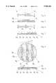
- FIG. 1an embodiment of the magnetic arrangement for therapeutic purposes
- FIG. 2a cross section along the line II--II in FIG. 1,
- FIG. 3a cross section through a second embodiment
- FIG. 4a further embodiment of the magnetic arrangement
- FIG. 5a variation of the embodiment according to FIG. 4,
- FIG. 6a further embodiment of the magnetic arrangement
- FIG. 7a further embodiment of the magnetic arrangement
- FIG. 8a plan-view of the magnetic arrangement according to FIG. 7,
- FIG. 9a variation of the embodiment according to FIG. 7,
- FIG. 10 to FIG. 14further embodiments of magnetic arrangements with differing pole configurations of the relevant bodies.
- the magnetic arrangements shown in FIGS. 1 to 3consist of a first magnetic body M 1 and a second magnetic body M 2 mechanically connected thereto, whereby the two magnetic bodies M 1 and M 2 show a high coercive field strength, the [BH] max -value of the first magnetic body M 1 being lower than that of the second body M 2 and the two magnetic bodies M 1 and M 2 building an active surface (surface of the magnetic arrangement shown in FIGS. 1 to 3) with reference to the intended effect of the magnetic field.
- the second body M 2is arranged on the active surface of the first body M 1 in the form of a flat piece.
- the second magnetic body M 2is embedded into the first magnetic body M 1 at its active surface.
- the active surface of the second magnetic body M 2is smaller than that of the first magnetic body M 1 .
- the vector sum of all magnetic fluxesis zero on the active surface of both magnetic bodies M 1 and M 2 .
- the following two examplesshow different magnetic materials for the magnetic bodies M 1 and M 2 and the appropriate values for the magnetic remanence B r , the coercive field strength i H c and the maximum magnetic energy product [BH] max .
- M 1consists of isotropic plastic bonded NdFeB.
- M 2consists of plastic bonded isotropic Ba-ferrite.
- M 1consists of isotropic sintered NdFeB.
- M 2consists of anisotropic plastic bonded Sr ferrite.
- the types of embodiments shown in FIGS. 4 to 14which are described below as examples, have proven to be particularly favourable for achieving a therapeutic effect.
- the magnetically higher value magnetic body M 2consisting of a permanent magnetic material with elements of the group of rare-earths, such as NdFeB or SmCo 5 , is in all cases smaller by area and volume than the magnetically lower value magnetic body M 1 , which, for example, consists of Sr-ferrite.
- circular or disc-shaped magnetsare used.
- other geometrical shapessuch as ovals, rectangulars, five, six or more cornered pieces, or other symmetrical or also asymmetrical tabular forms may be used.
- At least one magnetic body M 2 of higher energy densityis arranged on the surface of a magnetic body M 1 of lower energy density by either direct contact (FIG. 4) or, in special cases, also by an intermediate layer Z 1 , such as a glue, a plastic layer or other optional non-magnetizable medium, such as a fabric (FIG. 5).
- the magnetic arrangement as per FIG. 6, having already been basically described in FIG. 3,shows at least one magnetic body M 2 of higher energy density, being integrated into a magnetic body M 1 of lower energy density.
- the magnetic body M 2is inserted into a bore hole in magnetic body M 1 and there affixed by suitable fixing methods, such as glueing, welding, or covering of both sides with small self-adhesive discs, or similar.
- a gapis provided between the magnetic bodies M 1 and M 2 , according to the magnetic arrangement shown in FIGS. 7 and 8.
- several stripe-type magnetic bodies M 2 of higher energy densityare arranged between several stripe-type magnetic bodies M 1 of lower energy density.
- the active surface of magnetic body M 1is larger than that of magnetic body M 2 .
- the individual gap between the magnetic bodies M 1 and M 2is preferably up to 50 mm.
- the magnetic bodies M 1 and M 2consisting of different magnetic materials, are connected to one another into a circular magnetic arrangement by a rigid or elastic, i.e. flexible, connecting layer Z 1 .
- a ferro-magnetic keeper layer Z 2of, for example, low-carbon soft iron is provided on the side opposite to the active surface.
- a rigid or flexible layer of non-magnetizable materialsuch as non-magnetic stainless steel, aluminium or a plastic, or of a combination of these components, is arranged on the active surface of magnetic bodies M 1 and M 2 which, basically, ensures the stability of the magnetic arrangement.
- the magnetic bodies M 1 and M 2have on their active surface.
- the magnetic body M 1is magnetized in axial direction, i.e. vertical to its effective surface.
- FIGS. 10 to 14refer to other circular or rectangular magnetic arrangements whereby, as described above and shown in FIGS. 4 to 9, magnetic bodies M 2 of higher energy density build a mechanically connected effective unit with one or more magnetic bodies M 1 of lower energy density.
- FIGS. 12 to 14show two embodiments which have several magnetic bodies, for example M 2 and M 2 ' of higher energy density, whereby these magnetic bodies can, reference their geometric sizes and configurations and also in their energy density, be different.
- the magnetic flux density on the active surface, and the magnetic stray fieldcan be intensified and varied, so that these capacities may be even better adjusted to the individual application case and thereby achieve certain effects.
Landscapes
- Engineering & Computer Science (AREA)
- Health & Medical Sciences (AREA)
- Physics & Mathematics (AREA)
- Public Health (AREA)
- Biomedical Technology (AREA)
- Life Sciences & Earth Sciences (AREA)
- Animal Behavior & Ethology (AREA)
- General Health & Medical Sciences (AREA)
- Nuclear Medicine, Radiotherapy & Molecular Imaging (AREA)
- Veterinary Medicine (AREA)
- Radiology & Medical Imaging (AREA)
- General Physics & Mathematics (AREA)
- Theoretical Computer Science (AREA)
- Electromagnetism (AREA)
- Power Engineering (AREA)
- Mechanical Engineering (AREA)
- Magnetic Treatment Devices (AREA)
- Magnetic Bearings And Hydrostatic Bearings (AREA)
- Acyclic And Carbocyclic Compounds In Medicinal Compositions (AREA)
Abstract
Description
______________________________________ M.sub.1 M.sub.2 ______________________________________ B.sub.r [mT] 470 163 .sub.i H.sub.c [kA/m] 700 240 [BH].sub.max [kJ/m.sup.3 ] 35 4.5 ______________________________________
______________________________________ M.sub.1 M.sub.2 ______________________________________ B.sub.r [mT] 1,250 220 .sub.i H.sub.c [kA/m] 800 280 [BH].sub.max [kJ/m.sup.3 ] 280 9.0 ______________________________________
Claims (19)
Applications Claiming Priority (3)
| Application Number | Priority Date | Filing Date | Title |
|---|---|---|---|
| DE29515302 | 1995-09-25 | ||
| DE29515302UDE29515302U1 (en) | 1995-09-25 | 1995-09-25 | Magnet arrangement |
| PCT/DE1996/001395WO1997011749A1 (en) | 1995-09-25 | 1996-07-23 | Magnet arrangement for therapeutic use |
Publications (2)
| Publication Number | Publication Date |
|---|---|
| US5965282Atrue US5965282A (en) | 1999-10-12 |
| US5965282C1 US5965282C1 (en) | 2002-05-07 |
Family
ID=8013407
Family Applications (1)
| Application Number | Title | Priority Date | Filing Date |
|---|---|---|---|
| US08849436Expired - LifetimeUS5965282C1 (en) | 1995-09-25 | 1997-05-22 | Magnetic arrangement for therapeutic application |
Country Status (9)
| Country | Link |
|---|---|
| US (1) | US5965282C1 (en) |
| EP (1) | EP0793518B1 (en) |
| JP (1) | JP3137653B2 (en) |
| AT (1) | ATE233582T1 (en) |
| AU (1) | AU6732496A (en) |
| CA (1) | CA2205958C (en) |
| DE (2) | DE29515302U1 (en) |
| DK (1) | DK0793518T3 (en) |
| WO (1) | WO1997011749A1 (en) |
Cited By (33)
| Publication number | Priority date | Publication date | Assignee | Title |
|---|---|---|---|---|
| US6267719B1 (en) | 1999-09-01 | 2001-07-31 | Schering-Plough Healthcare Products, Inc. | Magnetic sheets |
| US6332862B1 (en)* | 1999-12-21 | 2001-12-25 | Michael Zandman | Articles of clothing incorporating magnets for therapeutic purposes |
| US6416458B1 (en) | 2000-07-12 | 2002-07-09 | Therion Research Inc. | Therapeutic flexible magnetic sheet and method |
| US6432036B1 (en) | 1999-12-15 | 2002-08-13 | Chi-Kyung Kim | Device for magnetic focus radiation medical treatment |
| US6761896B1 (en)* | 1998-10-29 | 2004-07-13 | Unilever Home & Personal Care Usa, Division Of Conopco, Inc. | Skin cosmetic care system and method |
| US6773391B1 (en)* | 1999-09-24 | 2004-08-10 | Bernard Bricot | Device and method of biostimulating living organisms and/or neutralizing the harmful effects of appliances operating with electric power |
| US20040167373A1 (en)* | 2003-02-26 | 2004-08-26 | Xie Robert Be | Method of acupuncture and magnetic treatment for weight loss |
| US6850140B1 (en) | 2003-09-10 | 2005-02-01 | Magnetic Technologies Corporation | Layered magnets and methods for producing same |
| WO2005058418A1 (en)* | 2003-12-12 | 2005-06-30 | Pilla Arthur A | Static magnetic field treatment apparatus and method |
| GB2413080A (en)* | 2004-03-19 | 2005-10-19 | Roger Edward Flaherty | Magnetic therapy device worn by animals having alternate pole concentric annular magnets |
| WO2006072593A3 (en)* | 2005-01-07 | 2006-12-21 | Iba Gmbh | Device for magnet assisted transfer of chemical compounds into cells and method for magnet assisted transfer of proteins into cells |
| US20090143811A1 (en)* | 2007-11-29 | 2009-06-04 | Tom Chi | Magnetic Acupuncture Needle |
| US20100058918A1 (en)* | 2008-09-11 | 2010-03-11 | Risolia Joseph R | Instrument pick |
| US20100179372A1 (en)* | 2009-01-13 | 2010-07-15 | Glassman Harry A | Method of enhancing skin appearance through the combination of Titan TM and TMR methods |
| US20110105828A1 (en)* | 2009-10-30 | 2011-05-05 | Magnetic Acupuncture, LLC | Methods of treating a body part |
| US20110184440A1 (en)* | 2010-01-26 | 2011-07-28 | Saldinger Pierre F | Magnetically manipulable surgical mesh and apparatus for the manipulation thereof |
| US20120108884A1 (en)* | 2010-10-29 | 2012-05-03 | Bechler Laurie A | Multi-polar magnetic devices for treating patients and methods therefor |
| WO2012115534A3 (en)* | 2011-02-22 | 2012-10-26 | Закрытое Акционерное Общество "Нанотехнология Мдт" | Magnetic module |
| ITAN20120075A1 (en)* | 2012-06-21 | 2013-12-22 | Andrea Epifano | DEVICE FOR MAGNETIC AURICOLOTHERAPY. |
| US9265966B2 (en) | 2011-10-07 | 2016-02-23 | Nikken International, Inc. | Dynamic multi-layer therapeutic magnetic device |
| WO2017004080A1 (en)* | 2015-07-01 | 2017-01-05 | The George Washington University | System and method for magnetically mediated plasma treatment of cancer with enhanced selectivity |
| US20180056082A1 (en)* | 2016-08-27 | 2018-03-01 | Zhongping Lou | Magnetic Moxibustion Chair |
| US10241850B2 (en) | 2013-10-02 | 2019-03-26 | Grid Logic Incorporated | Non-magnetodielectric flux concentrator |
| US10350683B2 (en) | 2013-10-02 | 2019-07-16 | Grid Logic Incorporated | Multiple flux concentrator heating |
| US11007600B2 (en) | 2013-06-10 | 2021-05-18 | Grid Logic Incorporated | System and method for additive manufacturing |
| US11446739B2 (en) | 2016-02-03 | 2022-09-20 | Grid Logic Incorporated | System and method for manufacturing a part |
| US11595768B2 (en) | 2016-12-02 | 2023-02-28 | Cochlear Limited | Retention force increasing components |
| US11792587B1 (en) | 2015-06-26 | 2023-10-17 | Cochlear Limited | Magnetic retention device |
| US11792586B2 (en) | 2015-09-14 | 2023-10-17 | Cochlear Limited | Retention magnet system for medical device |
| US11813672B2 (en) | 2020-05-08 | 2023-11-14 | Grid Logic Incorporated | System and method for manufacturing a part |
| US11918808B2 (en) | 2015-06-12 | 2024-03-05 | Cochlear Limited | Magnet management MRI compatibility |
| US12003925B2 (en) | 2014-07-29 | 2024-06-04 | Cochlear Limited | Magnetic retention system |
| US12420101B2 (en) | 2019-09-27 | 2025-09-23 | Cochlear Limited | Multipole magnet for medical implant system |
Families Citing this family (5)
| Publication number | Priority date | Publication date | Assignee | Title |
|---|---|---|---|---|
| DE19628722A1 (en)* | 1996-07-17 | 1998-01-22 | Esselte Meto Int Gmbh | Device for deactivating a securing element for electronic article surveillance |
| DE10321622A1 (en)* | 2003-05-13 | 2004-12-02 | Drumm Gmbh | Magnetic pin wall system for notice boards has clamp rotatable bar magnet clamp polarised orthogonal to length and clamped by rotating lever |
| DE202009010179U1 (en) | 2009-03-23 | 2009-10-08 | Rheinmagnet Horst Baermann Gmbh | edition |
| DE202010003676U1 (en) | 2010-03-17 | 2010-07-22 | Rheinmagnet Horst Baermann Gmbh | Light surface display |
| JP6472092B2 (en)* | 2016-08-31 | 2019-02-20 | バイオアイ株式会社 | Jewelry |
Citations (5)
| Publication number | Priority date | Publication date | Assignee | Title |
|---|---|---|---|---|
| DE3246128A1 (en)* | 1981-12-15 | 1983-06-23 | Fritz 7770 Überlingen Koch | Magnet arrangement for amplifying a magnetic force field, in particular for therapeutic purposes |
| DE3331061A1 (en)* | 1983-08-29 | 1985-03-14 | Horst 5064 Rösrath Baermann | Flexible magnetic foil for therapeutic purposes |
| DE3730077A1 (en)* | 1986-09-12 | 1988-04-14 | Marubeni Kk | DEVICE FOR MAGNETIC THERAPY AND MAGNETS HERE |
| US5017185A (en)* | 1985-03-29 | 1991-05-21 | Rheinmagnet, Horst Baermann, Gmbh | Permanent magnetic arrangement for therapeutic purposes |
| US5304111A (en)* | 1992-06-19 | 1994-04-19 | Nikken, Inc. | Therapeutic magnetic sheet with repeated curved magnetic areas |
Family Cites Families (25)
| Publication number | Priority date | Publication date | Assignee | Title |
|---|---|---|---|---|
| US2958019A (en)* | 1956-09-17 | 1960-10-25 | Indiana General Corp | Magnetic pad assembly |
| DE1788314U (en)* | 1958-06-24 | 1959-05-06 | Hugo Ross | LICENSE PLATE. |
| DE1439075A1 (en)* | 1961-05-05 | 1969-08-07 | Siemens Ag | Permanent magnet |
| DE1847318U (en)* | 1961-11-18 | 1962-02-22 | Maria Kirsch | ARRANGEMENT FOR ATTACHING LICENSE PLATES, IN PARTICULAR ON MOTOR VEHICLES. |
| US3488615A (en)* | 1966-02-03 | 1970-01-06 | Gen Telephone & Elect | Magnetic matrix defining pairs of oppositely poled permanent magnets |
| US3568115A (en)* | 1967-11-10 | 1971-03-02 | Ca Atomic Energy Ltd | Magnetic material multipole assembly |
| US3740289A (en)* | 1968-10-10 | 1973-06-19 | Allen Bradley Co | Method for making adhesive coated ferrite magnets |
| FR2114151A5 (en)* | 1970-11-18 | 1972-06-30 | Sermag | |
| DE2061718A1 (en)* | 1970-12-15 | 1972-07-06 | Krauss H | Permanent magnetic pad |
| DE2127813A1 (en)* | 1971-06-04 | 1972-12-14 | Herzog H | Magnetized blackboard - of permanently magnetized objects bonded with plastic fill to nonmagnetic baseboard |
| DE2232613A1 (en)* | 1972-07-03 | 1974-01-24 | Spodig Heinrich | METHODS FOR IMPROVING THE MAGNETIZATION BEHAVIOR, ESPECIALLY. ALL DIFFICULT AND VERY DIFFICULT MAGNETIZABLE PERMANENT MAGNETIC FERRO, FERRI MAGNET MATERIALS FOR ACHIEVING HIGH FLOW DENSITY B DEEP M (G) AND FIELD STRENGTH H DEEP M (OE) WHEN THE MAGNETIC IS USED AT THE SAME TIME, VERY SIGNIFICANTLY ONE |
| FR2219503B1 (en)* | 1973-02-27 | 1976-11-05 | Favre Joanny | |
| DE2510173A1 (en)* | 1975-03-08 | 1976-09-16 | Erich Kloeckner | Electro-magnetic hand massager - with independently rotating massager discs on both ends of a curved handle |
| CH612287A5 (en)* | 1975-05-22 | 1979-07-13 | Bbc Brown Boveri & Cie | |
| DE2527461C2 (en)* | 1975-06-20 | 1987-01-02 | Robert Bosch Gmbh, 7000 Stuttgart | Process for the production of anisotropic segment magnets for electrical machines |
| DE3026299A1 (en)* | 1980-07-11 | 1982-02-04 | Magnetfabrik Bonn Gmbh Vorm. Gewerkschaft Windhorst, 5300 Bonn | Assembly of closely spaced permanent magnets of alternate polarity - which are each mounted on own base with base slotted for final assembly |
| EP0134437B1 (en)* | 1983-07-14 | 1988-08-17 | Horst Baermann | Flexible magnetic sheet |
| FR2611306A1 (en) | 1986-09-12 | 1988-08-26 | Marubeni Kk | COMPOSITE MAGNET FOR INCORPORATING INTO A MAGNETIC THERAPEUTIC DEVICE |
| DE3641034A1 (en)* | 1986-12-01 | 1988-06-09 | Utsch Kg Erich | Device for temporarily fastening temporary and/or test drive number plates |
| DE8716016U1 (en)* | 1987-12-04 | 1989-03-30 | Magnetfabrik Bonn Gmbh Vorm. Gewerkschaft Windhorst, 5300 Bonn | Magnetic adhesive device, especially for license plates on motor vehicles |
| US5277692A (en)* | 1992-01-21 | 1994-01-11 | Vincent Ardizzone | Flexible magnetic pad with multi-directional constantly alternating polarity zones |
| FR2688060B1 (en)* | 1992-02-28 | 1994-04-15 | Snr Roulements | MAGNET STRUCTURE FOR DISPLACEMENT SENSOR. |
| DE9211140U1 (en)* | 1992-08-20 | 1992-10-22 | Vacuumschmelze Gmbh, 6450 Hanau | Holding magnet system |
| DE4241670A1 (en)* | 1992-12-10 | 1994-06-16 | Theodor Splithoff | Holder for sign on car's roof - uses magnets combined with rubber suckers at ends of T-shaped plate, upon which transverse sign is mounted |
| DE9413430U1 (en)* | 1994-08-19 | 1994-12-22 | Friedrich, Rainer, 21407 Deutsch Evern | Special magnet |
- 1995
- 1995-09-25DEDE29515302Upatent/DE29515302U1/ennot_activeExpired - Lifetime
- 1996
- 1996-07-23ATAT96927522Tpatent/ATE233582T1/enactive
- 1996-07-23DEDE59610195Tpatent/DE59610195D1/ennot_activeExpired - Lifetime
- 1996-07-23EPEP96927522Apatent/EP0793518B1/ennot_activeExpired - Lifetime
- 1996-07-23DKDK96927522Tpatent/DK0793518T3/enactive
- 1996-07-23AUAU67324/96Apatent/AU6732496A/ennot_activeAbandoned
- 1996-07-23CACA002205958Apatent/CA2205958C/ennot_activeExpired - Fee Related
- 1996-07-23JPJP09513049Apatent/JP3137653B2/ennot_activeExpired - Fee Related
- 1996-07-23WOPCT/DE1996/001395patent/WO1997011749A1/enactiveIP Right Grant
- 1997
- 1997-05-22USUS08849436patent/US5965282C1/ennot_activeExpired - Lifetime
Patent Citations (6)
| Publication number | Priority date | Publication date | Assignee | Title |
|---|---|---|---|---|
| DE3246128A1 (en)* | 1981-12-15 | 1983-06-23 | Fritz 7770 Überlingen Koch | Magnet arrangement for amplifying a magnetic force field, in particular for therapeutic purposes |
| DE3331061A1 (en)* | 1983-08-29 | 1985-03-14 | Horst 5064 Rösrath Baermann | Flexible magnetic foil for therapeutic purposes |
| US5017185A (en)* | 1985-03-29 | 1991-05-21 | Rheinmagnet, Horst Baermann, Gmbh | Permanent magnetic arrangement for therapeutic purposes |
| DE3730077A1 (en)* | 1986-09-12 | 1988-04-14 | Marubeni Kk | DEVICE FOR MAGNETIC THERAPY AND MAGNETS HERE |
| GB2196855A (en)* | 1986-09-12 | 1988-05-11 | Marubeni Kk | Magnetic therapeutic device |
| US5304111A (en)* | 1992-06-19 | 1994-04-19 | Nikken, Inc. | Therapeutic magnetic sheet with repeated curved magnetic areas |
Cited By (46)
| Publication number | Priority date | Publication date | Assignee | Title |
|---|---|---|---|---|
| US6761896B1 (en)* | 1998-10-29 | 2004-07-13 | Unilever Home & Personal Care Usa, Division Of Conopco, Inc. | Skin cosmetic care system and method |
| US6267719B1 (en) | 1999-09-01 | 2001-07-31 | Schering-Plough Healthcare Products, Inc. | Magnetic sheets |
| AU741320B2 (en)* | 1999-09-01 | 2001-11-29 | Schering-Plough Healthcare Products, Inc. | Magnetic sheets |
| US6773391B1 (en)* | 1999-09-24 | 2004-08-10 | Bernard Bricot | Device and method of biostimulating living organisms and/or neutralizing the harmful effects of appliances operating with electric power |
| US6432036B1 (en) | 1999-12-15 | 2002-08-13 | Chi-Kyung Kim | Device for magnetic focus radiation medical treatment |
| US6332862B1 (en)* | 1999-12-21 | 2001-12-25 | Michael Zandman | Articles of clothing incorporating magnets for therapeutic purposes |
| US6416458B1 (en) | 2000-07-12 | 2002-07-09 | Therion Research Inc. | Therapeutic flexible magnetic sheet and method |
| US20040167373A1 (en)* | 2003-02-26 | 2004-08-26 | Xie Robert Be | Method of acupuncture and magnetic treatment for weight loss |
| US6783504B1 (en) | 2003-02-26 | 2004-08-31 | Robert Be Xie | Method of acupuncture and magnetic treatment for weight loss |
| US6850140B1 (en) | 2003-09-10 | 2005-02-01 | Magnetic Technologies Corporation | Layered magnets and methods for producing same |
| WO2005058418A1 (en)* | 2003-12-12 | 2005-06-30 | Pilla Arthur A | Static magnetic field treatment apparatus and method |
| US20050215842A1 (en)* | 2003-12-12 | 2005-09-29 | Pilla Arthur A | Apparatus and method for static magnetic field treatment of tissue, organs, cells, and molecules |
| US7611453B2 (en) | 2003-12-12 | 2009-11-03 | Pilla Arthur A | Apparatus and method for static magnetic field treatment of tissue, organs, cells, and molecules |
| US20090306456A1 (en)* | 2003-12-12 | 2009-12-10 | Pilla Arthur A | Apparatus and method for static magnetic field treatment of tissue, organs, cells, and molecules |
| GB2413080A (en)* | 2004-03-19 | 2005-10-19 | Roger Edward Flaherty | Magnetic therapy device worn by animals having alternate pole concentric annular magnets |
| WO2006072593A3 (en)* | 2005-01-07 | 2006-12-21 | Iba Gmbh | Device for magnet assisted transfer of chemical compounds into cells and method for magnet assisted transfer of proteins into cells |
| US20090143811A1 (en)* | 2007-11-29 | 2009-06-04 | Tom Chi | Magnetic Acupuncture Needle |
| US8380298B2 (en)* | 2007-11-29 | 2013-02-19 | Tom Chi | Magnetic acupuncture needle |
| US20100058918A1 (en)* | 2008-09-11 | 2010-03-11 | Risolia Joseph R | Instrument pick |
| US7956264B2 (en)* | 2008-09-11 | 2011-06-07 | Risolia Joseph R | Instrument pick |
| US20100179372A1 (en)* | 2009-01-13 | 2010-07-15 | Glassman Harry A | Method of enhancing skin appearance through the combination of Titan TM and TMR methods |
| US20110105828A1 (en)* | 2009-10-30 | 2011-05-05 | Magnetic Acupuncture, LLC | Methods of treating a body part |
| US20110184440A1 (en)* | 2010-01-26 | 2011-07-28 | Saldinger Pierre F | Magnetically manipulable surgical mesh and apparatus for the manipulation thereof |
| US20120108884A1 (en)* | 2010-10-29 | 2012-05-03 | Bechler Laurie A | Multi-polar magnetic devices for treating patients and methods therefor |
| US8523754B2 (en)* | 2010-10-29 | 2013-09-03 | Laurie A. Bechler | Multi-polar magnetic devices for treating patients and methods therefor |
| US8764620B2 (en) | 2010-10-29 | 2014-07-01 | Laurie A. Bechler | Multi-polar magnetic devices for treating patients and methods therefor |
| US9113985B2 (en) | 2010-10-29 | 2015-08-25 | Blmj Holdings, Llc | Methods of treating dental patients using multi-polar magnetic devices |
| WO2012115534A3 (en)* | 2011-02-22 | 2012-10-26 | Закрытое Акционерное Общество "Нанотехнология Мдт" | Magnetic module |
| US9265966B2 (en) | 2011-10-07 | 2016-02-23 | Nikken International, Inc. | Dynamic multi-layer therapeutic magnetic device |
| ITAN20120075A1 (en)* | 2012-06-21 | 2013-12-22 | Andrea Epifano | DEVICE FOR MAGNETIC AURICOLOTHERAPY. |
| US11007600B2 (en) | 2013-06-10 | 2021-05-18 | Grid Logic Incorporated | System and method for additive manufacturing |
| US10241850B2 (en) | 2013-10-02 | 2019-03-26 | Grid Logic Incorporated | Non-magnetodielectric flux concentrator |
| US10350683B2 (en) | 2013-10-02 | 2019-07-16 | Grid Logic Incorporated | Multiple flux concentrator heating |
| US12003925B2 (en) | 2014-07-29 | 2024-06-04 | Cochlear Limited | Magnetic retention system |
| US11918808B2 (en) | 2015-06-12 | 2024-03-05 | Cochlear Limited | Magnet management MRI compatibility |
| US12383739B2 (en) | 2015-06-12 | 2025-08-12 | Cochlear Limited | Magnet management MRI compatibility |
| US11792587B1 (en) | 2015-06-26 | 2023-10-17 | Cochlear Limited | Magnetic retention device |
| WO2017004080A1 (en)* | 2015-07-01 | 2017-01-05 | The George Washington University | System and method for magnetically mediated plasma treatment of cancer with enhanced selectivity |
| US11792586B2 (en) | 2015-09-14 | 2023-10-17 | Cochlear Limited | Retention magnet system for medical device |
| US12137326B2 (en) | 2015-09-14 | 2024-11-05 | Cochlear Limited | Retention magnet system for medical device |
| US11446739B2 (en) | 2016-02-03 | 2022-09-20 | Grid Logic Incorporated | System and method for manufacturing a part |
| US20180056082A1 (en)* | 2016-08-27 | 2018-03-01 | Zhongping Lou | Magnetic Moxibustion Chair |
| US11595768B2 (en) | 2016-12-02 | 2023-02-28 | Cochlear Limited | Retention force increasing components |
| US12420101B2 (en) | 2019-09-27 | 2025-09-23 | Cochlear Limited | Multipole magnet for medical implant system |
| US11813672B2 (en) | 2020-05-08 | 2023-11-14 | Grid Logic Incorporated | System and method for manufacturing a part |
| US12202044B2 (en) | 2020-05-08 | 2025-01-21 | Grid Logic Incorporated | System and method for manufacturing a part |
Also Published As
| Publication number | Publication date |
|---|---|
| CA2205958A1 (en) | 1997-04-03 |
| AU6732496A (en) | 1997-04-17 |
| DK0793518T3 (en) | 2003-06-23 |
| US5965282C1 (en) | 2002-05-07 |
| EP0793518B1 (en) | 2003-03-05 |
| ATE233582T1 (en) | 2003-03-15 |
| DE59610195D1 (en) | 2003-04-10 |
| JPH09512739A (en) | 1997-12-22 |
| JP3137653B2 (en) | 2001-02-26 |
| EP0793518A1 (en) | 1997-09-10 |
| CA2205958C (en) | 2001-07-10 |
| WO1997011749A1 (en) | 1997-04-03 |
| DE29515302U1 (en) | 1995-11-30 |
Similar Documents
| Publication | Publication Date | Title |
|---|---|---|
| US5965282A (en) | Magnetic arrangement for therapeutic application | |
| US5635889A (en) | Dipole permanent magnet structure | |
| US5631616A (en) | Magnetic field generating device for use in MRI | |
| JPH0367425B2 (en) | ||
| US6178353B1 (en) | Laminated magnet keeper for implant device | |
| GB2205999A (en) | Magnetic device | |
| IL151755A0 (en) | Magnetic-based force/torque sensor | |
| WO2001063732A3 (en) | Methods and apparatus for selectively tailored electromagnetic fields of linear motors | |
| WO1993023859A1 (en) | Magnetization of permanent magnet strip materials | |
| US4544904A (en) | Composite magnet and magnetic circuit | |
| ES484089A1 (en) | Solenoid construction | |
| CA2183987A1 (en) | Dental Attachment | |
| US4401961A (en) | Permanent magnetic holding arrangement, particularly for temporary holding of ferro-magnetic parts | |
| US6126589A (en) | Therapeutic magnetic sheet | |
| EP0199872A1 (en) | Magnetic therapeutic instrument | |
| US5214404A (en) | Continuously magnetizing magnet | |
| EP0541872B1 (en) | Magnetic field generating apparatus for MRI | |
| GB1432969A (en) | ||
| KR102280885B1 (en) | Cosmetic device for improved transdermal penetration and method for manufacturing the same | |
| WO1994018682A1 (en) | Permanent magnet | |
| JPS61188316U (en) | ||
| JPH02155450A (en) | Magnetizing device for small motor assembly | |
| GB2069766A (en) | Improvements in or relating to methods of producing anisotropic permanent magnets and magnets produced by such methods | |
| JPS6028092Y2 (en) | magnetic chuck | |
| JPS644361Y2 (en) |
Legal Events
| Date | Code | Title | Description |
|---|---|---|---|
| AS | Assignment | Owner name:RHEINMAGNET HORST BAERMANN GMBH, GERMANY Free format text:ASSIGNMENT OF ASSIGNORS INTEREST;ASSIGNOR:BAERMANN, HORST;REEL/FRAME:008634/0094 Effective date:19970422 | |
| STCF | Information on status: patent grant | Free format text:PATENTED CASE | |
| AS | Assignment | Owner name:BAERMANN MAGNETICS INC., SOUTH CAROLINA Free format text:ASSIGNMENT OF ASSIGNORS INTEREST;ASSIGNOR:RHEINMAGNET HORST BAERMANN GMBH;REEL/FRAME:010881/0876 Effective date:20000531 | |
| RR | Request for reexamination filed | Effective date:20000712 | |
| B1 | Reexamination certificate first reexamination | Free format text:CLAIMS 2, 8 AND 13-15 ARE CANCELLED. CLAIMS 1, 3 AND 19 ARE DETERMINED TO BE PATENTABLE AS AMENDED. CLAIMS 4-7, 9-12 AND 16-18, DEPENDENT ON AN AMENDED CLAIM, ARE DETERMINED TO BE PATENTABLE. NEW CLAIM 20 IS ADDED AND DETERMINED TO BE PATENTABLE. | |
| C1 | Reexamination certificate (1st level) | ||
| FEPP | Fee payment procedure | Free format text:PAYOR NUMBER ASSIGNED (ORIGINAL EVENT CODE: ASPN); ENTITY STATUS OF PATENT OWNER: SMALL ENTITY | |
| FPAY | Fee payment | Year of fee payment:4 | |
| FPAY | Fee payment | Year of fee payment:8 | |
| AS | Assignment | Owner name:RHEINMAGNET HORST BAERMANN GMBH, GERMANY Free format text:ASSIGNMENT OF ASSIGNORS INTEREST;ASSIGNOR:BAERMANN MAGNETICS INC.;REEL/FRAME:019215/0458 Effective date:20070419 | |
| FPAY | Fee payment | Year of fee payment:12 |