US5964792A - Convertible thermal blanket - Google Patents
Convertible thermal blanketDownload PDFInfo
- Publication number
- US5964792A US5964792AUS08/965,306US96530697AUS5964792AUS 5964792 AUS5964792 AUS 5964792AUS 96530697 AUS96530697 AUS 96530697AUS 5964792 AUS5964792 AUS 5964792A
- Authority
- US
- United States
- Prior art keywords
- inflatable
- thermal blanket
- covering
- blanket
- extension
- Prior art date
- Legal status (The legal status is an assumption and is not a legal conclusion. Google has not performed a legal analysis and makes no representation as to the accuracy of the status listed.)
- Expired - Lifetime
Links
Images


Classifications
- A—HUMAN NECESSITIES
- A61—MEDICAL OR VETERINARY SCIENCE; HYGIENE
- A61F—FILTERS IMPLANTABLE INTO BLOOD VESSELS; PROSTHESES; DEVICES PROVIDING PATENCY TO, OR PREVENTING COLLAPSING OF, TUBULAR STRUCTURES OF THE BODY, e.g. STENTS; ORTHOPAEDIC, NURSING OR CONTRACEPTIVE DEVICES; FOMENTATION; TREATMENT OR PROTECTION OF EYES OR EARS; BANDAGES, DRESSINGS OR ABSORBENT PADS; FIRST-AID KITS
- A61F7/00—Heating or cooling appliances for medical or therapeutic treatment of the human body
- A61F7/0097—Blankets with active heating or cooling sources
- A—HUMAN NECESSITIES
- A61—MEDICAL OR VETERINARY SCIENCE; HYGIENE
- A61F—FILTERS IMPLANTABLE INTO BLOOD VESSELS; PROSTHESES; DEVICES PROVIDING PATENCY TO, OR PREVENTING COLLAPSING OF, TUBULAR STRUCTURES OF THE BODY, e.g. STENTS; ORTHOPAEDIC, NURSING OR CONTRACEPTIVE DEVICES; FOMENTATION; TREATMENT OR PROTECTION OF EYES OR EARS; BANDAGES, DRESSINGS OR ABSORBENT PADS; FIRST-AID KITS
- A61F7/00—Heating or cooling appliances for medical or therapeutic treatment of the human body
- A61F2007/0059—Heating or cooling appliances for medical or therapeutic treatment of the human body with an open fluid circuit
- A61F2007/006—Heating or cooling appliances for medical or therapeutic treatment of the human body with an open fluid circuit of gas
Definitions
- This inventionrelates generally to thermal blankets and, more particularly, to thermal blankets that deliver a bath of a thermally-controlled medium to a body.
- a patient's body temperatureis controlled during surgery by using operating room blankets that cover the parts of a patient's body not being operated upon. Multiple blankets are overlaid, or variously shaped blankets having cut-outs or flaps are used, to cover most of the patient and still provide access to target surgical sites. After surgery, the patient is covered with a full-body blanket that covers all of the patient except for the head. Thus, as much of the patient as possible is kept covered duriing surgery to keep the patient warm while providing access to the operating site and after surgery a full body blanket keeps the patient warm.
- the prior art inflatable coveringis an inflatable blanket that includes an array of apertures on its underside.
- the thermally-controlled mediumis exhausted from the apertures into the erected structure and bathes the patient in the inflating medium.
- the temperature of the environment provided by the inflated blanketis determined by the temperature of the inflating medium.
- Such thermal blanketsare advantageously used to warm or cool patients before, during, and after surgery.
- a patientis covered with the blanket and a blanket area around the site of interest is sealed to provide a boundary against deflation.
- the blanket within the sealed areacan be cut out, creating an open space in the blanket for access to the site of interest, while maintaining the inflatable integrity of the blanket.
- the blanketcan then be inflated with the thermally-controlled medium to completely cover the patient except for the site of interest and thereby control the patient's temperature during surgery.
- the inflatable blanketcan be removed and replaced with a full-body blanket or a supplemental blanket can be draped across the exposed site. See, for example, U.S. patent application Ser. No. 071638,748, commonly assigned with this application and incorporated herein by this reference.
- thermal blanketthat can be used to cover a patient during surgery or other medical procedures in which it is necessary to gain access to a portion of the patient's body and that also can be used after the medical procedure is completed to fully cover the patient and provide a thermally-controlled environment.
- the present inventionsatisfies this need.
- an inflatable, self-erecting thermal blanketincludes one or more portions that are gathered in a non-inflated condition and held there by a closure such that a thermally-controlled inflating medium that is admitted into the blanket is prevented from being admitted into the gathered portion(s), thereby inflating a primary part of the blanket, which can be used to cover a patient, and leaving a void in the area covered by the blanket so as to expose an area of the patient's body for medical treatment.
- the closurecan be released, thereby permitting the inflating medium to be admitted into the gathered portion such that the gathered portion inflates and covers the exposed area of the patient's body.
- the released thermal blanketthen covers the entire patient and bathes the patient in the inflating medium.
- a single thermal blanketcan be used to provide a thermally controlled environment and expose an area of a patient during treatment and also can be converted to fully cover the patient after treatment.
- the gathered portion of the thermal blanketis created by rolling or folding an extension of the blanket onto itself and is maintained in the gathered condition adjacent the primary portion of the blanket by a closure comprising an elongated strip of tape that bridges both the gathered portion and the primary portion.
- the stripis provided with a release element that permits the gathered portion of the strip to be separated from the primary portion of the strip. When a patient is to be fully covered, the release element releases the gathered portion, which is then inflated by the inflating medium and covers a previously exposed area of the patient.
- the closure and the release elementcan be provided by a variety of structures.
- the closurecomprises a strip that includes two longitudinal edges, one of which is attached to the gathered portion and the other of which is attached to the primary portion of the thermal blanket.
- the stripcan include a central perforation that can be split open such that the gathered portion edge of the strip can be separated from the primary portion edge of the strip, releasing the gathered portion of the thermal blanket and permitting it to be unfurled and inflated.
- the release elementcan comprise a tear string embedded in a strip that bridges the gathered portion and primary portion. When the patient is to be fully covered, the tear string can be pulled out of the strip to separate the two edges of the strip and release the gathered portion.
- the release elementcan comprise a releasable hook and loop system having a hook strip attached to either the gathered portion or the primary portion and a loop strip attached to the other portion.
- the hook stripcan be easily separated from the loop strip.
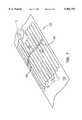
- FIG. 1is a view of an inflatable thermal blanket constructed in accordance with the present invention to initially cover a patient's lower body, having a gathered portion of the blanket in a non-inflated condition to permit access to the patient's upper body during medical treatment.
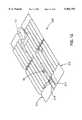
- FIG. 2is a view of the blanket illustrated in FIG. 1 after the gathered portion has been released and the patient fully covered.
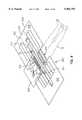
- FIG. 3 and FIG. 4are views illustrating construction details of the blanket illustrated in FIGS. 1 and 2.
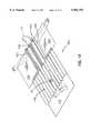
- FIG. 5is an exploded view of the blanket illustrated in FIG. 1 showing the closure before attachment to the blanket.
- FIG. 6 and FIG. 7are views of an inflatable thermal blanket constructed in accordance with the present invention to provide access to a patient's lower body during medical treatment.
- FIG. 8 and FIG. 9are views of another inflatable thermal blanket constructed in accordance with the present invention to provide access to a patient's lower body during medical treatment.
- FIG. 10, FIG. 11, and FIG. 12are views of a third inflatable thermal blanket constructed in accordance with the present invention to provide access to a patient's lower body during medical treatment.
- FIG. 13 and FIG. 14are views of an inflatable thermal blanket constructed in accordance with the present invention to provide access to a patient's upper body during medical treatment.
- FIG. 15 and FIG. 16are views of an inflatable thermal blanket constructed in accordance with the present invention having alternative closures to those illustrated in FIGS. 1-14.
- FIG. 1shows an inflatable thermal blanket 10 constructed in accordance with the present invention.
- the blanketprovides access to the upper body of a patient 12 during medical treatment and includes a lower end 14 that is placed near the feet of the patient and an upper end rolled onto itself to form a gathered portion 16 and a primary portion 17.
- An inlet port 18 of the blanketis connected by a hose 19 to a heater/blower assembly 20 that produces a thermally controlled inflating medium, such as heat and air.
- Medical treatmentcan then be provided to the exposed torso of the patient while the remainder of the patient's body is kept warm by the blanket.
- a closure 24maintains the gathered portion 16 in a non-inflated condition. After the medical treatment has been completed, the closure is opened so as to release the gathered portion, permitting the inflating medium to enter the gathered portion, inflating it so that it assumes the configuration illustrated in FIG. 2. In this way, the same blanket can be used to keep an area of the patient's body warm during medical treatment and then can be converted into a full body covering after completion of treatment.
- FIG. 3 and FIG. 4illustrate some of the construction details of the thermal blanket 10.
- a lower sheet 49 of the blanketis formed by bonding a layer 50 of flexible material to a layer 52 of heat-sealable plastic.
- the layers 50 and 52respectively comprise a layer of non-woven polyester pre-laminated with a layer of heat sealable plastic such as a polypropylene extrusion.
- An upper layer 53 of the thermal blanketconsists of a layer of extruded polypropylene film bonded to the plastic underside layer 52 by a heat-sealing process to form interrupted seams, one of which is indicated by the arrow 54, and inflatable tubes, one of which is indicated by the arrow 55.
- the seam 54forms a passageway 56 between two adjacent tubes 55 and 57.
- the thermal blanket 10bathes a patient in the thermally controlled inflating medium by means of a plurality of apertures 62 illustrated in FIG. 4.
- the aperturesextend through the blanket underside, which includes the layers 50 and 52.
- the apertures 62are provided in a pattern determined to produce a uniform flow of the inflating medium from the underside of the blanket.
- the aperturesare provided in a density that varies inversely with the distance of the aperture to the center tube having the inlet port 18.
- the ambient temperature beneath the inflated blanketis substantially uniform from edge to edge.
- FIG. 5illustrates the manner of attaching the closure 24 to the blanket in the gathered position.
- the closurecomprises an elongated strip having a first edge 26 that is attached to the primary portion 17 of the thermal blanket and a second edge 28 attached to the gathered portion 16 of the blanket.
- the closure 24is shown in phantom, and therefore a strip of adhesive backing 30 applied along the underside of the first edge is indicated by shading, as is another strip of adhesive backing 32 applied along the underside of the second edge.
- the elongated strip of the closure 24bridges the primary portion 17 and the gathered portion 16, thereby holding the gathered portion 16 in the rolled, non-inflated condition. In this way, when the inflating medium is admitted into the thermal blanket to inflate the primary portion 17 through the inlet 18, the gathered portion does not inflate.
- FIG. 5also shows that a central tear strip 34 is defined between the first edge 26 and second edge 28 of the closure 24 by two parallel perforations 36, 38 that extend along the length of the closure strip. It should be apparent that one end 40 of the tear strip can be grasped and pulled, tearing the perforations apart, thereby releasing the first edge from the second edge, permitting the gathered portion to be unfurled, and permitting the inflating medium to be admitted into the gathered portion to inflate the blanket and assume the condition illustrated in FIG. 2.
- the closure 24also can include an attachment flap 70 that extends outwardly from the second edge 28 of the closure.
- a free edge 72 of the attachment flapis provided with a strip of adhesive 74 on its underside along its length.
- the adhesiveis used to attach the flap to the patient's body, thereby holding the gathered portion 16 in a fixed relative location. Holding the gathered portion fixed assists the attending medical personnel in maintaining the thermal blanket 10 in a desired location while medical treatment is provided.
- the attachment flap 70preferably also includes a perforation 76 that can be torn, thereby releasing the closure 24 (and also the gathered portion 16) from the attachment flap.
- the attachment flapcan be released independently of, or along with, the elongated strip of the closure 24.
- FIG. 6 and FIG. 7illustrate a thermal blanket 100 that provides access to the lower extremities of the patient 12 while covering the torso of the patient during treatment.
- the heater/blower assembly 20 and connected hose 19are not shown for clarity of illustration, but it should be understood that these elements are included in any actual usage of the thermal blanket.
- FIG. 6illustrates the blanket 100 in the gathered condition
- FIG. 7illustrates the blanket in the fully deployed condition.
- a gathered portion 116 and a primary portion 117are provided by rolling one end of the thermal blanket onto itself while in a non-inflated condition and maintaining it in the non-inflated condition with a closure 124.
- an attachment flap 170can be provided, if desired, with an adhesive strip backing 174 for attaching the gathered portion to the body of the patient.
- the unfurled gathered portionends in a lower edge 180 at the feet of the patient 12.
- the primary edge 126 of the released closureremains attached to the surface 122 of the blanket, as illustrated in FIG. 7.
- FIGS. 8 and 9illustrate an alternative embodiment of a blanket 200 for providing access to the lower extremities of the patient.
- FIG. 8shows that the blanket can be draped over a patient so that the longest dimension of the blanket extends across the body of the patient from arm to arm.
- Two gathered portions 210, 212define a central area 214 of the blanket, which covers the torso of the patient and bridges a blanket lower end 216 and a blanket upper end 218.
- the lower end and upper endare each provided with an inlet port 18 but communicate internally so that both ends are simultaneously inflated even if only one port is connected to an inflating medium.
- An optional head drape 220can be provided to maintain the temperature of the patient's head.
- the blanket 200also includes, in its upper end 218, a removeable section 219 defined by a U-shaped perforation 221.
- the removeable section 219can be removed by tearing along the perforation 221 to leave a U-shaped indentation in the upper end edge 223.
- the indentationis indicated at 224 in FIG. 9.
- FIG. 9shows the blanket 200 after medical care has been provided and the gathered portions have been released. As can be seen in FIG. 9, after the gathered portions are released, the blanket 200 is preferably rotated so that the longest dimension of the blanket is oriented over the length of the patient's body with the patient's head received in the U-shaped indentation 224. Thus, complete coverage of the patient is obtained.
- FIGS. 10-12illustrate an embodiment 300 of the thermal blanket in which access is provided to the lower extremities of the patient 12 in general, and to the legs of the patient in particular.
- FIG. 10shows that the thermal blanket has an overall shape that includes a primary portion having a relatively large, generally rectangular upper body portion 310 placed over the upper body of the patient 12 and a relatively narrow, elongated central lower body extension 312 having a width substantially less than the width of the upper body portion.
- the lower body extension 312comprises a single inflatable tube of the type illustrated in FIGS. 3 and 4 that is used to cover at least one elongated member of the patient, such as a leg.
- the upper body portioncomprises a plurality of inflatable tubes that are arranged transversely of the upper end of the lower body extension and are used to cover the chest area of the patient.
- the elongated central extension 312 and the transverse upperbody tubes 310communicate internally so that a single inlet port 18 permits them to be simultaneously inflated.
- FIG. 10also shows that the lower end of the elongated lower body extension 312 is flanked by two gathered portions 314, 316.
- Each gathered portionincludes an attachment flap 322 with an adhesive backing along its underside, as described previously for the other embodiments.
- Other attachment flapscan be provided at other blanket portions as desired, such as the attachment flaps 324 for securing edges of the upper body portion 310 to the patient 12.
- a head drape 326also can be provided.
- FIG. 11shows a first one 314 of the gathered portions in its deployed condition
- FIG. 12shows the thermal blanket with both gathered portions in their respective deployed conditions, wherein full coverage of the patient is provided.
- FIG. 10shows both of the gathered portions 314, 316 in their non-inflated condition and shows that they are coupled to the central extension 312 of the blanket 300 along the length of the central extension, on opposite sides.
- Each gathered portion 314, 316has a closure 315, 317, respectively, that maintains the gathered portions in their non-inflated condition.
- FIG. 11shows the blanket 300 after the closure 315 of the first gathered portion 314 has been opened, or removed, thereby permitting the inflating medium to enter the first gathered portion and inflate the first gathered portion so that it deploys transversely of the central extension 312.
- the closure 317 of the remaining second gathered portion 316has not been removed and therefore that gathered portion remains in the non-inflated condition.
- FIG. 12shows the blanket 300 after the closure 317 of the second gathered portion 316 also has been opened and after the second gathered portion has been inflated and deployed transversely of the central extension.
- FIGS. 13 and 14illustrate a blanket 400 similar to that shown in FIGS. 10-12, except that the blanket 400 leaves the arms of the patient 12 exposed and covers the lower extremities of the patient.
- the lower end 412 of the blanketcovers the patient's lower extremities and the upper end 414 includes the gathered portions.
- the primary portion of the blanketincludes a relatively large portion 416 and a central extension 418 that is flanked by two gathered portions 420, 422.
- the gathered portionstypically are deployed after medical care has been provided (FIG. 14) and it is desired to obtain full coverage of the patient.
- Lateral drapes 424can be provided for supplemental coverage, if desired.
- the closure 24 of a thermal blanket constructed in accordance with the present inventioncan assume a variety of structures in addition to the pull strip described above.
- the closurecomprises a tear string 510 that is embedded in the elongated strip 524 of the closure.
- the elongated closure stripincludes a first edge 526 attached to the primary portion 14 of the blanket 10 and a second edge 528 attached to the gathered portion 16.
- the tear stringincludes an enlarged release tab 512 that can be grasped and pulled, tearing the string out from the elongated strip and thereby separating the edge of the elongated strip attached to the primary portion of the blanket from the edge of the elongated strip attached to the gathered portion.
- an optional attachment flap 70can be provided, having a free end 72 with an adhesive backing 74 applied to the underside and having a central perforation 76 for easy removal.
- FIG. 16shows a closure 24 comprising a hook and loop fastening system 610, such as commonly sold, for example, under the trademark "VELCRO.”
- the hook and loop fastening systemincludes a hook strip 612 having loops or coils 613 of a plastic material and a loop strip 614 having a loose, or fuzzy, pile of material.
- the hook stripcan be engaged with the loop strip and then released by forcibly pulling them apart. Although relatively modest forces will not separate the two strips, more deliberate pulling actions can be used to easily separate the hook strip from the loop strip.
- the hook and loop fastening systemprovides a unitary strip that can be attached to the thermal blanket so as to maintain the gathered portion in the non-inflated condition.
- the looped plastic materialis attached to the underside of a first edge 616 of the hook strap, which then is attached to the gathered portion 16 along a second edge 618.
- the attachmentis by an adhesive backing.
- the loop strip 614is attached to the primary portion 14 of the thermal blanket. It should be noted that the hook strip and loop strip can be mounted on the opposite blanket portions.
- the hook and loop fastening systemis simply separated by pulling on the two respective strips in opposite directions. This releases the hook strip from the loop strip and permits the gathered portion to be unfurled, admitting the inflating medium into the gathered portion.
- an attachment flap 70can be included with the closure 610.
- all of the embodiments described aboveprovide an inflatable thermal blanket that can be used to permit access to a site of interest while controlling a patient's body temperature during surgery and then can be converted to a full-body covering that completely covers the patient.
Landscapes
- Health & Medical Sciences (AREA)
- Engineering & Computer Science (AREA)
- Biomedical Technology (AREA)
- Heart & Thoracic Surgery (AREA)
- Vascular Medicine (AREA)
- Life Sciences & Earth Sciences (AREA)
- Animal Behavior & Ethology (AREA)
- General Health & Medical Sciences (AREA)
- Public Health (AREA)
- Veterinary Medicine (AREA)
- Thermotherapy And Cooling Therapy Devices (AREA)
Abstract
Description
Claims (22)
Priority Applications (2)
| Application Number | Priority Date | Filing Date | Title |
|---|---|---|---|
| US08/965,306US5964792A (en) | 1996-08-02 | 1997-11-06 | Convertible thermal blanket |
| US09/363,560US6290716B1 (en) | 1994-09-30 | 1999-07-29 | Convertible thermal blanket |
Applications Claiming Priority (2)
| Application Number | Priority Date | Filing Date | Title |
|---|---|---|---|
| US08/691,593US5733318A (en) | 1994-09-30 | 1996-08-02 | Convertible thermal blanket |
| US08/965,306US5964792A (en) | 1996-08-02 | 1997-11-06 | Convertible thermal blanket |
Related Parent Applications (1)
| Application Number | Title | Priority Date | Filing Date |
|---|---|---|---|
| US08/691,593ContinuationUS5733318A (en) | 1994-09-30 | 1996-08-02 | Convertible thermal blanket |
Related Child Applications (1)
| Application Number | Title | Priority Date | Filing Date |
|---|---|---|---|
| US09/363,560ContinuationUS6290716B1 (en) | 1994-09-30 | 1999-07-29 | Convertible thermal blanket |
Publications (1)
| Publication Number | Publication Date |
|---|---|
| US5964792Atrue US5964792A (en) | 1999-10-12 |
Family
ID=24777160
Family Applications (2)
| Application Number | Title | Priority Date | Filing Date |
|---|---|---|---|
| US08/965,306Expired - LifetimeUS5964792A (en) | 1994-09-30 | 1997-11-06 | Convertible thermal blanket |
| US09/363,560Expired - Fee RelatedUS6290716B1 (en) | 1994-09-30 | 1999-07-29 | Convertible thermal blanket |
Family Applications After (1)
| Application Number | Title | Priority Date | Filing Date |
|---|---|---|---|
| US09/363,560Expired - Fee RelatedUS6290716B1 (en) | 1994-09-30 | 1999-07-29 | Convertible thermal blanket |
Country Status (1)
| Country | Link |
|---|---|
| US (2) | US5964792A (en) |
Cited By (28)
| Publication number | Priority date | Publication date | Assignee | Title |
|---|---|---|---|---|
| US6290716B1 (en)* | 1994-09-30 | 2001-09-18 | Augustine Medical, Inc. | Convertible thermal blanket |
| WO2002000132A1 (en)* | 2000-06-29 | 2002-01-03 | Alain Pierre Xavier Carjuzaa | Surgical draping device and elimination of peroperational thermolysis risks |
| US20030135251A1 (en)* | 2002-01-17 | 2003-07-17 | Wayne Schuessler | Inflatable blanket for use in cardiac surgery |
| US20060231683A1 (en)* | 2005-04-18 | 2006-10-19 | Orr James R | Aircraft & motor vehicle protection system that eliminates eleven safety and environmental hazards associated with aircraft and vehicles parked or tied down and exposed to the elements and animals |
| US20070068929A1 (en)* | 2005-09-29 | 2007-03-29 | Augustine Scott D | Bus bar interface for conductive fabric heaters |
| US20070068930A1 (en)* | 2005-09-29 | 2007-03-29 | Augustine Scott D | Electric warming blanket having optimized temperature zones |
| US20080103567A1 (en)* | 2006-10-13 | 2008-05-01 | Augustine Scott D | Heating blanket |
| US20080173629A1 (en)* | 2007-01-18 | 2008-07-24 | Augustine Biomedical And Design Llc | Shut-off timer for a heating blanket |
| US20080230530A1 (en)* | 2007-03-19 | 2008-09-25 | Augustine Biomedical And Design, Llc | Heating blanket |
| US20090099630A1 (en)* | 2007-10-12 | 2009-04-16 | Augustine Biomedical And Design Llc | Tuckable electric warming blanket for patient warming |
| US20100161016A1 (en)* | 2008-12-19 | 2010-06-24 | Augustine Biomedical And Design, Llc | Apparatus and method for effectively warming a patient |
| EP2398359B1 (en)* | 2009-02-18 | 2016-09-14 | Smiths Medical ASD, Inc. | Combination underbody and overbody blanket |
| WO2017070359A1 (en)* | 2015-10-23 | 2017-04-27 | Cleanco Bioscience Group, Llc | Uv sterilization apparatus, system, and method for forced-air patient heating systems |
| WO2018075576A1 (en)* | 2016-10-21 | 2018-04-26 | 3M Innovative Properties Company | Multi-sectional patient warming blanket |
| US9962122B2 (en) | 2014-04-10 | 2018-05-08 | Augustine Temperature Management LLC | Underbody warming systems |
| US9974880B2 (en) | 2012-07-27 | 2018-05-22 | Mark D. Krosney | Air sterilization and disinfection apparatus |
| US10201935B2 (en) | 2007-03-19 | 2019-02-12 | Augustine Temperature Management LLC | Electric heating pad |
| US10206248B2 (en) | 2014-11-13 | 2019-02-12 | Augustine Temperature Management LLC | Heated underbody warming systems with electrosurgical grounding |
| US10765580B1 (en) | 2019-03-27 | 2020-09-08 | Augustine Biomedical And Design, Llc | Patient securement system for the surgical trendelenburg position |
| US11000622B2 (en) | 2012-07-27 | 2021-05-11 | Aeroclean Technologies, Llc | UV sterilization apparatus, system, and method for forced-air patient heating systems |
| US11406729B2 (en) | 2017-08-31 | 2022-08-09 | Aeroclean Technologies, Llc | Air treatment system and method |
| US11452382B2 (en) | 2007-03-19 | 2022-09-27 | Augustine Temperature Management LLC | Electric heating pad with electrosurgical grounding |
| US11590023B2 (en) | 2016-10-21 | 2023-02-28 | 3M Innovative Properties Company | Low profile forced-air blanket |
| US11779675B2 (en) | 2020-10-19 | 2023-10-10 | Molekule Group, Inc. | Air sterilization insert for heating, ventilation, and air conditioning (HVAC) systems |
| US11844733B1 (en) | 2022-06-23 | 2023-12-19 | Augustine Biomedical And Design, Llc | Patient securement system for the surgical Trendelenburg position |
| US11850336B2 (en) | 2020-05-22 | 2023-12-26 | Molekule Group, Inc. | UV sterilization apparatus, system, and method for aircraft air systems |
| WO2024126632A1 (en)* | 2022-12-16 | 2024-06-20 | Ilo Technology | Protective heating sheet for a device for transporting human beings |
| US12151038B2 (en) | 2020-09-14 | 2024-11-26 | Molekule Group, Inc. | Integrated air sanitizer and surface disinfector |
Families Citing this family (17)
| Publication number | Priority date | Publication date | Assignee | Title |
|---|---|---|---|---|
| US6843800B1 (en) | 1998-01-23 | 2005-01-18 | Innercool Therapies, Inc. | Patient temperature regulation method and apparatus |
| US6991645B2 (en) | 1998-01-23 | 2006-01-31 | Innercool Therapies, Inc. | Patient temperature regulation method and apparatus |
| US6830581B2 (en) | 1999-02-09 | 2004-12-14 | Innercool Therspies, Inc. | Method and device for patient temperature control employing optimized rewarming |
| US6869440B2 (en) | 1999-02-09 | 2005-03-22 | Innercool Therapies, Inc. | Method and apparatus for patient temperature control employing administration of anti-shivering agents |
| WO2003015672A1 (en) | 2001-08-15 | 2003-02-27 | Innercool Therapies, Inc. | Method and apparatus for patient temperature control employing administration of anti-shivering |
| US6859967B2 (en) | 2002-02-22 | 2005-03-01 | Samuel W. Harrison | Overlay mattress |
| US7041122B2 (en)* | 2003-12-05 | 2006-05-09 | Gaymar Industries, Inc. | Inflatable blanket with a tie |
| US8470012B2 (en) | 2004-09-08 | 2013-06-25 | Arizant Healthcare Inc. | Inflatable convective pad for surgery |
| US7658756B2 (en)* | 2006-04-12 | 2010-02-09 | Smiths Medical Asd, Inc. | Hose retainer for thermal blanket |
| US8197525B2 (en)* | 2009-02-13 | 2012-06-12 | Smiths Medical Asd, Inc. | Full body split access blanket |
| US9622907B2 (en) | 2010-09-10 | 2017-04-18 | Medivance Incorporated | Cooling medical pad |
| US20150173941A1 (en)* | 2013-12-20 | 2015-06-25 | Brandon Cuongquoc Giap | Forced air temperature regulating pad with triple-layer technology |
| US20180049915A1 (en)* | 2013-12-20 | 2018-02-22 | Bcg Medical, Llc | Forced air temperature regulating pad with chest warming feature |
| US11395759B2 (en) | 2014-08-18 | 2022-07-26 | Medline Industries, Lp | Method and apparatus pertaining to securement of a personal patient warming apparatus |
| JP6787903B2 (en) | 2015-01-27 | 2020-11-18 | メディヴァンス インコーポレイテッドMedivance,Inc. | Improved medical pads and systems for hyperthermia |
| US12433785B2 (en) | 2021-02-23 | 2025-10-07 | C. R. Bard, Inc. | Gel pad assembly using free rotatable fluid joints |
| US12241570B2 (en) | 2021-07-07 | 2025-03-04 | C. R. Bard, Inc. | Negative pressure connector seal |
Citations (43)
| Publication number | Priority date | Publication date | Assignee | Title |
|---|---|---|---|---|
| DE113420C (en)* | ||||
| US222690A (en)* | 1879-12-16 | Improvement in surgical bandages | ||
| US1399095A (en)* | 1919-12-02 | 1921-12-06 | Sr Jean F Webb | Vacuo-thermic-body-treatment appliance |
| US1777982A (en)* | 1928-02-20 | 1930-10-07 | Popp Karl | Hot-air mat |
| US2093834A (en)* | 1934-04-30 | 1937-09-21 | Gen Motors Corp | Refrigerating apparatus |
| US2110022A (en)* | 1935-07-15 | 1938-03-01 | Internat Engineering Corp | Cover |
| US2122964A (en)* | 1934-03-27 | 1938-07-05 | Ernest J Sweetland | Drying apparatus |
| US2512559A (en)* | 1945-01-18 | 1950-06-20 | Alfred L W Williams | Comfort unit |
| US2601189A (en)* | 1949-08-22 | 1952-06-17 | Theodore Backer | Air comforter bed covering |
| GB716746A (en)* | 1952-05-05 | 1954-10-13 | Rowland Vance Lee | An air conditioning cover for use on beds or for covering parts of the human body |
| US2706988A (en)* | 1951-11-19 | 1955-04-26 | Jarolux A G | Human body heat treating apparatus |
| US3243827A (en)* | 1963-05-27 | 1966-04-05 | Mildred M Kintner | Bedding securing structure |
| US3418726A (en)* | 1966-12-19 | 1968-12-31 | Westinghouse Electric Corp | Hair dryer |
| US3610323A (en)* | 1969-10-20 | 1971-10-05 | Dan E Troyer | Cool coat |
| US3610251A (en)* | 1968-07-25 | 1971-10-05 | Riveril Trading Co Ltd | Appliance for the heat treatment of a human being |
| US3691646A (en)* | 1971-01-22 | 1972-09-19 | Hector Michael Ruffolo | Hair dryer |
| US3714947A (en)* | 1971-02-11 | 1973-02-06 | Angelica Corp | Hypothermia baby bunting |
| US3757366A (en)* | 1971-08-18 | 1973-09-11 | W Sacher | Cushion for preventing and alleviating bedsores |
| GB1334935A (en)* | 1971-03-02 | 1973-10-24 | Howorth Air Conditioning Ltd | Mattress |
| GB1461383A (en)* | 1973-04-28 | 1977-01-13 | Howorth Air Conditioning Ltd | Covers for levitation beds |
| GB1532219A (en)* | 1975-06-28 | 1978-11-15 | Howorth Air Eng Ltd | Mattress |
| GB1566207A (en)* | 1976-05-21 | 1980-04-30 | Gaymar Ind Inc | Flexible heating or cooling pad |
| DE3308553A1 (en)* | 1983-03-10 | 1984-09-20 | Udo Prof. Dr.med. 4130 Moers Smidt | COOLING PAD FOR THE HUMAN BODY |
| WO1985003216A1 (en)* | 1984-01-18 | 1985-08-01 | Bailey David F | Multi-layer disposable medical thermal blanket |
| US4572188A (en)* | 1984-03-05 | 1986-02-25 | Augustine Scott D | Airflow cover for controlling body temperature |
| US4660388A (en)* | 1984-05-24 | 1987-04-28 | Greene Jr George J | Cooling cover |
| US4777802A (en)* | 1987-04-23 | 1988-10-18 | Steve Feher | Blanket assembly and selectively adjustable apparatus for providing heated or cooled air thereto |
| US4807644A (en)* | 1987-02-12 | 1989-02-28 | Vastech Medical Products Inc. | Temperature-regulating surgical drape |
| EP0311336A1 (en)* | 1987-10-05 | 1989-04-12 | Augustine Medical, Inc. | Thermal blanket |
| US4867230A (en)* | 1988-04-11 | 1989-09-19 | Gene Voss | Convection blanket warmer |
| US5125238A (en)* | 1991-04-29 | 1992-06-30 | Progressive Dynamics, Inc. | Patient warming or cooling blanket |
| US5184612A (en)* | 1987-10-05 | 1993-02-09 | Augustine Medical, Inc. | Thermal blanket with transparent upper body drape |
| US5300101A (en)* | 1987-10-05 | 1994-04-05 | Augustine Medical, Inc. | Method and apparatus for treatment of pediatric hypothermia |
| US5300102A (en)* | 1987-10-05 | 1994-04-05 | Augustine Medical, Inc. | Thermal blanket |
| US5300100A (en)* | 1990-08-22 | 1994-04-05 | Advanced Warming Systems, Inc. | Body warmer |
| US5336250A (en)* | 1987-10-05 | 1994-08-09 | Augustine Medical, Inc. | Thermal blanket with transparent upper body drape |
| US5343579A (en)* | 1992-08-03 | 1994-09-06 | Mallinckrodt Medical, Inc. | Warming blanket having multiple inlets |
| US5350417A (en)* | 1993-05-18 | 1994-09-27 | Augustine Medical, Inc. | Convective thermal blanket |
| US5383918A (en)* | 1992-08-31 | 1995-01-24 | Panetta; Thomas F. | Hypothermia reducing body exclosure |
| US5405370A (en)* | 1991-11-08 | 1995-04-11 | Irani; Feraidoon | Air blanket |
| US5405371A (en)* | 1987-10-05 | 1995-04-11 | Augustine Medical, Inc. | Thermal blanket |
| US5443488A (en)* | 1994-08-15 | 1995-08-22 | Progressive Dynamics, Inc. | Thermal blanket with surgical access |
| US5545194A (en)* | 1994-09-30 | 1996-08-13 | Augustine Medical, Inc. | Convertible thermal blanket |
Family Cites Families (2)
| Publication number | Priority date | Publication date | Assignee | Title |
|---|---|---|---|---|
| US5964792A (en)* | 1996-08-02 | 1999-10-12 | Augustine Medical, Inc. | Convertible thermal blanket |
| US5735890A (en)* | 1995-10-18 | 1998-04-07 | Mallinckrodt Medical, Inc. | Inflatable blanket having access slits |
- 1997
- 1997-11-06USUS08/965,306patent/US5964792A/ennot_activeExpired - Lifetime
- 1999
- 1999-07-29USUS09/363,560patent/US6290716B1/ennot_activeExpired - Fee Related
Patent Citations (48)
| Publication number | Priority date | Publication date | Assignee | Title |
|---|---|---|---|---|
| DE113420C (en)* | ||||
| US222690A (en)* | 1879-12-16 | Improvement in surgical bandages | ||
| US1399095A (en)* | 1919-12-02 | 1921-12-06 | Sr Jean F Webb | Vacuo-thermic-body-treatment appliance |
| US1777982A (en)* | 1928-02-20 | 1930-10-07 | Popp Karl | Hot-air mat |
| US2122964A (en)* | 1934-03-27 | 1938-07-05 | Ernest J Sweetland | Drying apparatus |
| US2093834A (en)* | 1934-04-30 | 1937-09-21 | Gen Motors Corp | Refrigerating apparatus |
| US2110022A (en)* | 1935-07-15 | 1938-03-01 | Internat Engineering Corp | Cover |
| US2512559A (en)* | 1945-01-18 | 1950-06-20 | Alfred L W Williams | Comfort unit |
| US2601189A (en)* | 1949-08-22 | 1952-06-17 | Theodore Backer | Air comforter bed covering |
| US2706988A (en)* | 1951-11-19 | 1955-04-26 | Jarolux A G | Human body heat treating apparatus |
| GB716746A (en)* | 1952-05-05 | 1954-10-13 | Rowland Vance Lee | An air conditioning cover for use on beds or for covering parts of the human body |
| US3243827A (en)* | 1963-05-27 | 1966-04-05 | Mildred M Kintner | Bedding securing structure |
| US3418726A (en)* | 1966-12-19 | 1968-12-31 | Westinghouse Electric Corp | Hair dryer |
| US3610251A (en)* | 1968-07-25 | 1971-10-05 | Riveril Trading Co Ltd | Appliance for the heat treatment of a human being |
| US3610323A (en)* | 1969-10-20 | 1971-10-05 | Dan E Troyer | Cool coat |
| US3691646A (en)* | 1971-01-22 | 1972-09-19 | Hector Michael Ruffolo | Hair dryer |
| US3714947A (en)* | 1971-02-11 | 1973-02-06 | Angelica Corp | Hypothermia baby bunting |
| GB1334935A (en)* | 1971-03-02 | 1973-10-24 | Howorth Air Conditioning Ltd | Mattress |
| US3757366A (en)* | 1971-08-18 | 1973-09-11 | W Sacher | Cushion for preventing and alleviating bedsores |
| GB1461383A (en)* | 1973-04-28 | 1977-01-13 | Howorth Air Conditioning Ltd | Covers for levitation beds |
| GB1532219A (en)* | 1975-06-28 | 1978-11-15 | Howorth Air Eng Ltd | Mattress |
| GB1566207A (en)* | 1976-05-21 | 1980-04-30 | Gaymar Ind Inc | Flexible heating or cooling pad |
| DE3308553A1 (en)* | 1983-03-10 | 1984-09-20 | Udo Prof. Dr.med. 4130 Moers Smidt | COOLING PAD FOR THE HUMAN BODY |
| WO1985003216A1 (en)* | 1984-01-18 | 1985-08-01 | Bailey David F | Multi-layer disposable medical thermal blanket |
| US4572188A (en)* | 1984-03-05 | 1986-02-25 | Augustine Scott D | Airflow cover for controlling body temperature |
| US4660388A (en)* | 1984-05-24 | 1987-04-28 | Greene Jr George J | Cooling cover |
| US4807644A (en)* | 1987-02-12 | 1989-02-28 | Vastech Medical Products Inc. | Temperature-regulating surgical drape |
| US4777802A (en)* | 1987-04-23 | 1988-10-18 | Steve Feher | Blanket assembly and selectively adjustable apparatus for providing heated or cooled air thereto |
| US5184612A (en)* | 1987-10-05 | 1993-02-09 | Augustine Medical, Inc. | Thermal blanket with transparent upper body drape |
| EP0311336A1 (en)* | 1987-10-05 | 1989-04-12 | Augustine Medical, Inc. | Thermal blanket |
| US5405371A (en)* | 1987-10-05 | 1995-04-11 | Augustine Medical, Inc. | Thermal blanket |
| US5300101A (en)* | 1987-10-05 | 1994-04-05 | Augustine Medical, Inc. | Method and apparatus for treatment of pediatric hypothermia |
| US5300102A (en)* | 1987-10-05 | 1994-04-05 | Augustine Medical, Inc. | Thermal blanket |
| US5324320A (en)* | 1987-10-05 | 1994-06-28 | Augustine Medical, Inc. | Thermal blanket |
| US5336250A (en)* | 1987-10-05 | 1994-08-09 | Augustine Medical, Inc. | Thermal blanket with transparent upper body drape |
| US5620482A (en)* | 1987-10-05 | 1997-04-15 | Augustine Medical, Inc. | Inflatable thermal blanket with a foot drape |
| US4867230A (en)* | 1988-04-11 | 1989-09-19 | Gene Voss | Convection blanket warmer |
| US5300100A (en)* | 1990-08-22 | 1994-04-05 | Advanced Warming Systems, Inc. | Body warmer |
| US5125238A (en)* | 1991-04-29 | 1992-06-30 | Progressive Dynamics, Inc. | Patient warming or cooling blanket |
| US5405370A (en)* | 1991-11-08 | 1995-04-11 | Irani; Feraidoon | Air blanket |
| US5360439A (en)* | 1992-08-03 | 1994-11-01 | Mallinckrodt Medical, Inc. | Warming blanket method utilizing a warming blanket having multiple inlets |
| US5384924A (en)* | 1992-08-03 | 1995-01-31 | Mallinckrodt Medical, Inc. | Warming blanket having multiple inlets |
| US5514169A (en)* | 1992-08-03 | 1996-05-07 | Mallinckrodt Medical, Inc. | Warming blanket having multiple inlets |
| US5343579A (en)* | 1992-08-03 | 1994-09-06 | Mallinckrodt Medical, Inc. | Warming blanket having multiple inlets |
| US5383918A (en)* | 1992-08-31 | 1995-01-24 | Panetta; Thomas F. | Hypothermia reducing body exclosure |
| US5350417A (en)* | 1993-05-18 | 1994-09-27 | Augustine Medical, Inc. | Convective thermal blanket |
| US5443488A (en)* | 1994-08-15 | 1995-08-22 | Progressive Dynamics, Inc. | Thermal blanket with surgical access |
| US5545194A (en)* | 1994-09-30 | 1996-08-13 | Augustine Medical, Inc. | Convertible thermal blanket |
Non-Patent Citations (7)
| Title |
|---|
| McGraw Hill Encyclopedia of Science & Technology, 7th Ed., p. 713, definition of bonding .* |
| McGraw-Hill Encyclopedia of Science & Technology, 7th Ed., p. 713, definition of "bonding". |
| Normothermia in the OR Augustine Medical, Inc., Oct. 1989.* |
| Webster s Ninth New Collegiate Dictionary definition of laminate .* |
| Webster s Third New International Dictionary, p. 250, definition of bond .* |
| Webster's Ninth New Collegiate Dictionary definition of "laminate". |
| Webster's Third New International Dictionary, p. 250, definition of "bond". |
Cited By (67)
| Publication number | Priority date | Publication date | Assignee | Title |
|---|---|---|---|---|
| US6290716B1 (en)* | 1994-09-30 | 2001-09-18 | Augustine Medical, Inc. | Convertible thermal blanket |
| WO2002000132A1 (en)* | 2000-06-29 | 2002-01-03 | Alain Pierre Xavier Carjuzaa | Surgical draping device and elimination of peroperational thermolysis risks |
| FR2810875A1 (en)* | 2000-06-29 | 2002-01-04 | Alain Pierre Xavier Carjuzaa | DEVICE FOR SURGICAL DRAPING AND FOR THE FIGHT AGAINST PEROPERATORY THERMOLYSIS |
| US20070118195A1 (en)* | 2002-01-17 | 2007-05-24 | Wayne Schuessler | Inflatable blanket for use in cardiac surgery |
| US20030135251A1 (en)* | 2002-01-17 | 2003-07-17 | Wayne Schuessler | Inflatable blanket for use in cardiac surgery |
| US7172616B2 (en) | 2002-01-17 | 2007-02-06 | Nellcor Puritan Bennett Inc. | Inflatable blanket for use in cardiac surgery |
| US7951184B2 (en) | 2002-01-17 | 2011-05-31 | Mallinckrodt Inc. | Inflatable blanket for use in cardiac surgery |
| US20060231683A1 (en)* | 2005-04-18 | 2006-10-19 | Orr James R | Aircraft & motor vehicle protection system that eliminates eleven safety and environmental hazards associated with aircraft and vehicles parked or tied down and exposed to the elements and animals |
| US20110233185A1 (en)* | 2005-09-29 | 2011-09-29 | Augustine Temperature Management LLC | Heating blankets and pads |
| US8604391B2 (en) | 2005-09-29 | 2013-12-10 | Augustine Temperature Management LLC | Heating blankets and pads |
| US20070068930A1 (en)* | 2005-09-29 | 2007-03-29 | Augustine Scott D | Electric warming blanket having optimized temperature zones |
| US20070080155A1 (en)* | 2005-09-29 | 2007-04-12 | Augustine Scott D | Heating blankets and pads |
| WO2007041389A1 (en)* | 2005-09-29 | 2007-04-12 | Augustine Biomedical And Design Llc | Heating blanket and pads |
| US20070068928A1 (en)* | 2005-09-29 | 2007-03-29 | Augustine Scott D | Temperature sensor assemblies for electric warming blankets |
| US20070068929A1 (en)* | 2005-09-29 | 2007-03-29 | Augustine Scott D | Bus bar interface for conductive fabric heaters |
| US20070068931A1 (en)* | 2005-09-29 | 2007-03-29 | Augustine Scott D | Novel designs for an electric warming blanket including a flexible heater |
| US20070068923A1 (en)* | 2005-09-29 | 2007-03-29 | Augustine Scott D | Bus bar coupling for conductive fabric heaters |
| US7851729B2 (en) | 2005-09-29 | 2010-12-14 | Augustine Temperature Management LLC | Electric warming blanket having optimized temperature zones |
| US7714255B2 (en) | 2005-09-29 | 2010-05-11 | Augustine Biomedical And Design, Llc | Bus bar attachments for flexible heating elements |
| US7786408B2 (en) | 2005-09-29 | 2010-08-31 | Hot Dog International Llc | Bus bar interfaces for flexible heating elements |
| US20100204763A1 (en)* | 2005-09-29 | 2010-08-12 | Hot Dog International Llc | Temperature sensor assemblies for electric warming blankets |
| US8062343B2 (en) | 2006-10-13 | 2011-11-22 | Augustine Temperature Management LLC | Heating blanket |
| US20080103567A1 (en)* | 2006-10-13 | 2008-05-01 | Augustine Scott D | Heating blanket |
| US8624164B2 (en) | 2007-01-18 | 2014-01-07 | Augustine Temperature Management LLC | Shut-off timer for a heating blanket |
| US20080173629A1 (en)* | 2007-01-18 | 2008-07-24 | Augustine Biomedical And Design Llc | Shut-off timer for a heating blanket |
| US8283602B2 (en) | 2007-03-19 | 2012-10-09 | Augustine Temperature Management LLC | Heating blanket |
| US12011883B2 (en) | 2007-03-19 | 2024-06-18 | Augustine Temperature Management LLC | Electric heating pad |
| US11388782B2 (en) | 2007-03-19 | 2022-07-12 | Augustine Temperature Management LLC | Heating blanket |
| US20080230530A1 (en)* | 2007-03-19 | 2008-09-25 | Augustine Biomedical And Design, Llc | Heating blanket |
| US8772676B2 (en) | 2007-03-19 | 2014-07-08 | Augustine Temperature Management LLC | Heating blanket |
| US11691350B2 (en) | 2007-03-19 | 2023-07-04 | Augustine Temperature Management LLC | Electric heating pad |
| US11465364B2 (en) | 2007-03-19 | 2022-10-11 | Augustine Temperature Management LLC | Electric heating pad |
| US10849193B2 (en) | 2007-03-19 | 2020-11-24 | Augustine Temperature Management LLC | Electric heating blanket or pad |
| US10506668B2 (en) | 2007-03-19 | 2019-12-10 | Augustine Temperature Management LLC | Heating blanket |
| US11452382B2 (en) | 2007-03-19 | 2022-09-27 | Augustine Temperature Management LLC | Electric heating pad with electrosurgical grounding |
| US10201935B2 (en) | 2007-03-19 | 2019-02-12 | Augustine Temperature Management LLC | Electric heating pad |
| US20090099630A1 (en)* | 2007-10-12 | 2009-04-16 | Augustine Biomedical And Design Llc | Tuckable electric warming blanket for patient warming |
| US20100161016A1 (en)* | 2008-12-19 | 2010-06-24 | Augustine Biomedical And Design, Llc | Apparatus and method for effectively warming a patient |
| EP2398359B1 (en)* | 2009-02-18 | 2016-09-14 | Smiths Medical ASD, Inc. | Combination underbody and overbody blanket |
| US9974880B2 (en) | 2012-07-27 | 2018-05-22 | Mark D. Krosney | Air sterilization and disinfection apparatus |
| US11000622B2 (en) | 2012-07-27 | 2021-05-11 | Aeroclean Technologies, Llc | UV sterilization apparatus, system, and method for forced-air patient heating systems |
| US9962122B2 (en) | 2014-04-10 | 2018-05-08 | Augustine Temperature Management LLC | Underbody warming systems |
| US10959675B2 (en) | 2014-04-10 | 2021-03-30 | Augustine Temperature Management LLC | Patient securing overlay for underbody supports |
| US11559259B2 (en) | 2014-04-10 | 2023-01-24 | Augustine Temperature Management LLC | Patient securing overlay for underbody supports |
| US10575784B2 (en) | 2014-04-10 | 2020-03-03 | Augustine Temperature Management LLC | Patient securing overlay for heated underbody supports |
| US10433792B2 (en) | 2014-04-10 | 2019-10-08 | Augustine Temperature Management LLC | Underbody warming systems |
| US11103188B2 (en) | 2014-04-10 | 2021-08-31 | Augustine Temperature Management LLC | Patient securing overlay for underbody supports |
| US10206248B2 (en) | 2014-11-13 | 2019-02-12 | Augustine Temperature Management LLC | Heated underbody warming systems with electrosurgical grounding |
| WO2017070359A1 (en)* | 2015-10-23 | 2017-04-27 | Cleanco Bioscience Group, Llc | Uv sterilization apparatus, system, and method for forced-air patient heating systems |
| US11590023B2 (en) | 2016-10-21 | 2023-02-28 | 3M Innovative Properties Company | Low profile forced-air blanket |
| WO2018075576A1 (en)* | 2016-10-21 | 2018-04-26 | 3M Innovative Properties Company | Multi-sectional patient warming blanket |
| US11234860B2 (en) | 2016-10-21 | 2022-02-01 | 3M Innovative Properties Company | Multi-sectional patient warming blanket |
| US11406729B2 (en) | 2017-08-31 | 2022-08-09 | Aeroclean Technologies, Llc | Air treatment system and method |
| US10765580B1 (en) | 2019-03-27 | 2020-09-08 | Augustine Biomedical And Design, Llc | Patient securement system for the surgical trendelenburg position |
| US12097152B2 (en) | 2019-03-27 | 2024-09-24 | Augustine Biomedical And Design, Llc | Patient securement system for the surgical Trendelenburg position |
| US11576833B2 (en) | 2019-03-27 | 2023-02-14 | Augustine Medical and Design, LLC | Patient securement system for the surgical Trendelenburg position |
| US10993866B2 (en) | 2019-03-27 | 2021-05-04 | Augustine Biomedical And Design, Llc | Patient securement system for the surgical trendelenburg position |
| US11278463B2 (en) | 2019-03-27 | 2022-03-22 | Augustine Biomedical And Design, Llc | Patient securement system for the surgical Trendelenburg position |
| US11801188B2 (en) | 2019-03-27 | 2023-10-31 | Augustine Biomedical And Design, Llc | Patient securement system for the surgical Trendelenburg position |
| US10980694B2 (en) | 2019-03-27 | 2021-04-20 | Augustine Biomedical And Design, Llc | Patient securement system for the surgical Trendelenburg position |
| US11382817B2 (en) | 2019-03-27 | 2022-07-12 | Augustine Biomedical And Design, Llc | Patient securement system for the surgical Trendelenburg position |
| US11850336B2 (en) | 2020-05-22 | 2023-12-26 | Molekule Group, Inc. | UV sterilization apparatus, system, and method for aircraft air systems |
| US12151038B2 (en) | 2020-09-14 | 2024-11-26 | Molekule Group, Inc. | Integrated air sanitizer and surface disinfector |
| US11779675B2 (en) | 2020-10-19 | 2023-10-10 | Molekule Group, Inc. | Air sterilization insert for heating, ventilation, and air conditioning (HVAC) systems |
| US11844733B1 (en) | 2022-06-23 | 2023-12-19 | Augustine Biomedical And Design, Llc | Patient securement system for the surgical Trendelenburg position |
| FR3143298A1 (en)* | 2022-12-16 | 2024-06-21 | Ilo Technology | Heated mattress and human transport device incorporating such a mattress |
| WO2024126632A1 (en)* | 2022-12-16 | 2024-06-20 | Ilo Technology | Protective heating sheet for a device for transporting human beings |
Also Published As
| Publication number | Publication date |
|---|---|
| US6290716B1 (en) | 2001-09-18 |
Similar Documents
| Publication | Publication Date | Title |
|---|---|---|
| US5964792A (en) | Convertible thermal blanket | |
| US5545194A (en) | Convertible thermal blanket | |
| US5792216A (en) | Methods of preventing hypothermia using an upper body warming blanket | |
| JP4083804B2 (en) | Inflatable blanket with slit for entry | |
| US7871429B2 (en) | Multifunction warming device with provision for being secured | |
| US6309409B1 (en) | Inflatable thermal blanket with provision for being secured during use | |
| EP1003449B1 (en) | System for convective warming of a patient during cardiac surgery | |
| US5974605A (en) | Warming blanket having multiple inlets | |
| US8097031B2 (en) | Warming device with provisions for deploying elements of an upper body convective apparatus and for deploying the lower portion of the warming device |
Legal Events
| Date | Code | Title | Description |
|---|---|---|---|
| STCF | Information on status: patent grant | Free format text:PATENTED CASE | |
| CC | Certificate of correction | ||
| FPAY | Fee payment | Year of fee payment:4 | |
| CC | Certificate of correction | ||
| AS | Assignment | Owner name:ARIZANT HEALTHCARE INC., MINNESOTA Free format text:ASSIGNMENT OF ASSIGNORS INTEREST;ASSIGNOR:AUGUSTINE MEDICAL, INC.;REEL/FRAME:013804/0785 Effective date:20030217 | |
| AS | Assignment | Owner name:MERRILL LYNCH CAPITAL, A DIVISION OF MERRILL LYNCH Free format text:SECURITY INTEREST;ASSIGNOR:ARIZANT HEALTHCARE INC.;REEL/FRAME:015629/0084 Effective date:20040730 | |
| FPAY | Fee payment | Year of fee payment:8 | |
| AS | Assignment | Owner name:GENERAL ELECTRIC CAPITAL CORPORATION,AS ADMINISTRA Free format text:SECURITY AGREEMENT;ASSIGNOR:ARIZANT HEALTHCARE INC.;REEL/FRAME:022813/0114 Effective date:20090611 | |
| AS | Assignment | Owner name:ARIZANT HEALTHCARE INC., MINNESOTA Free format text:RELEASE BY SECURED PARTY;ASSIGNOR:GE BUSINESS FINANCIAL SERVICES INC. (F/K/A MERRILL LYNCH BUSINESS FINANCIAL SERVICES INC.), AS ADMINISTRATIVE AGENT;REEL/FRAME:022813/0325 Effective date:20090611 | |
| AS | Assignment | Owner name:GENERAL ELECTRIC CAPITAL CORPORATION, MARYLAND Free format text:ASSIGNMENT OF ASSIGNORS INTEREST;ASSIGNOR:ARIZANT HEALTHCARE INC.;REEL/FRAME:025137/0066 Effective date:20101013 | |
| FEPP | Fee payment procedure | Free format text:PAT HOLDER NO LONGER CLAIMS SMALL ENTITY STATUS, ENTITY STATUS SET TO UNDISCOUNTED (ORIGINAL EVENT CODE: STOL); ENTITY STATUS OF PATENT OWNER: LARGE ENTITY | |
| AS | Assignment | Owner name:ARIZANT HEALTHCARE INC., MINNESOTA Free format text:CORRECTIVE ASSIGNMENT TO CORRECT THE NATURE OF THE CONVEYANCE AS A RELEASE BY SECURED PARTY, AND THE IDENTITY OF THE ASSIGNOR AND ASSIGNEE PREVIOUSLY RECORDED ON REEL 025137 FRAME 0066. ASSIGNOR(S) HEREBY CONFIRMS THE RELEASE OF SECURITY INTEREST IN ALL OF GRANTOR'S RIGHT, TITLE AND INTEREST IN PATENT RIGHTS;ASSIGNOR:GENERAL ELECTRIC CAPITAL CORPORATION, AS ADMINISTRATIVE AGENT;REEL/FRAME:025444/0901 Effective date:20101013 | |
| FPAY | Fee payment | Year of fee payment:12 | |
| AS | Assignment | Owner name:3M INNOVATIVE PROPERTIES COMPANY, MINNESOTA Free format text:ASSIGNMENT OF ASSIGNORS INTEREST;ASSIGNOR:ARIZANT HEALTHCARE INC.;REEL/FRAME:032040/0362 Effective date:20131212 |