US5964776A - Internal keratome apparatus and method for using the same to form a pocket/flap between layers of a live cornea - Google Patents
Internal keratome apparatus and method for using the same to form a pocket/flap between layers of a live corneaDownload PDFInfo
- Publication number
- US5964776A US5964776AUS08/936,509US93650997AUS5964776AUS 5964776 AUS5964776 AUS 5964776AUS 93650997 AUS93650997 AUS 93650997AUS 5964776 AUS5964776 AUS 5964776A
- Authority
- US
- United States
- Prior art keywords
- live cornea
- cornea
- live
- separating
- Prior art date
- Legal status (The legal status is an assumption and is not a legal conclusion. Google has not performed a legal analysis and makes no representation as to the accuracy of the status listed.)
- Expired - Lifetime
Links
- 210000004087corneaAnatomy0.000titleclaimsabstractdescription287
- 238000000034methodMethods0.000titleclaimsabstractdescription30
- 230000007246mechanismEffects0.000claimsdescription16
- 230000003287optical effectEffects0.000claimsdescription12
- 230000000087stabilizing effectEffects0.000claimsdescription9
- 210000000695crystalline lenAnatomy0.000description12
- 210000004027cellAnatomy0.000description10
- LFQSCWFLJHTTHZ-UHFFFAOYSA-NEthanolChemical compoundCCOLFQSCWFLJHTTHZ-UHFFFAOYSA-N0.000description8
- 210000001525retinaAnatomy0.000description8
- 239000000203mixtureSubstances0.000description7
- 210000000981epitheliumAnatomy0.000description6
- 210000003560epithelium cornealAnatomy0.000description5
- 230000008859changeEffects0.000description4
- 238000004891communicationMethods0.000description3
- 210000002919epithelial cellAnatomy0.000description3
- 239000007943implantSubstances0.000description3
- 239000000463materialSubstances0.000description3
- 238000000926separation methodMethods0.000description3
- 238000001356surgical procedureMethods0.000description3
- 206010020675HypermetropiaDiseases0.000description2
- 208000029091Refraction diseaseDiseases0.000description2
- NIXOWILDQLNWCW-UHFFFAOYSA-Nacrylic acid groupChemical groupC(C=C)(=O)ONIXOWILDQLNWCW-UHFFFAOYSA-N0.000description2
- 230000004430ametropiaEffects0.000description2
- 210000002159anterior chamberAnatomy0.000description2
- 201000009310astigmatismDiseases0.000description2
- 230000008878couplingEffects0.000description2
- 238000010168coupling processMethods0.000description2
- 238000005859coupling reactionMethods0.000description2
- 230000004438eyesightEffects0.000description2
- 239000012530fluidSubstances0.000description2
- 239000011521glassSubstances0.000description2
- 230000004305hyperopiaEffects0.000description2
- 201000006318hyperopiaDiseases0.000description2
- 238000012986modificationMethods0.000description2
- 230000004048modificationEffects0.000description2
- 208000014733refractive errorDiseases0.000description2
- 229910000811surgical stainless steelInorganic materials0.000description2
- 229920002994synthetic fiberPolymers0.000description2
- 229910000831SteelInorganic materials0.000description1
- 210000001742aqueous humorAnatomy0.000description1
- 230000004323axial lengthEffects0.000description1
- 230000006378damageEffects0.000description1
- 230000007547defectEffects0.000description1
- 230000007812deficiencyEffects0.000description1
- 229910003460diamondInorganic materials0.000description1
- 239000010432diamondSubstances0.000description1
- 208000037265diseases, disorders, signs and symptomsDiseases0.000description1
- 230000000694effectsEffects0.000description1
- 238000011065in-situ storageMethods0.000description1
- 238000003780insertionMethods0.000description1
- 230000037431insertionEffects0.000description1
- 239000002184metalSubstances0.000description1
- 230000004379myopiaEffects0.000description1
- 208000001491myopiaDiseases0.000description1
- 239000004033plasticSubstances0.000description1
- 238000003825pressingMethods0.000description1
- 230000009528severe injuryEffects0.000description1
- 239000010935stainless steelSubstances0.000description1
- 239000010959steelSubstances0.000description1
- 208000029257vision diseaseDiseases0.000description1
Images


Classifications
- A—HUMAN NECESSITIES
- A61—MEDICAL OR VETERINARY SCIENCE; HYGIENE
- A61F—FILTERS IMPLANTABLE INTO BLOOD VESSELS; PROSTHESES; DEVICES PROVIDING PATENCY TO, OR PREVENTING COLLAPSING OF, TUBULAR STRUCTURES OF THE BODY, e.g. STENTS; ORTHOPAEDIC, NURSING OR CONTRACEPTIVE DEVICES; FOMENTATION; TREATMENT OR PROTECTION OF EYES OR EARS; BANDAGES, DRESSINGS OR ABSORBENT PADS; FIRST-AID KITS
- A61F9/00—Methods or devices for treatment of the eyes; Devices for putting in contact-lenses; Devices to correct squinting; Apparatus to guide the blind; Protective devices for the eyes, carried on the body or in the hand
- A61F9/007—Methods or devices for eye surgery
- A61F9/013—Instruments for compensation of ocular refraction ; Instruments for use in cornea removal, for reshaping or performing incisions in the cornea
Definitions
- the present inventionrelates to an internal keratome apparatus and method of using the same to form a pocket between layers of a live cornea More particularly, the present invention relates to an internal keratome apparatus having a circularly-shaped reciprocating blade, and a method for using the same to form a circularly-shaped pocket between layers of a live cornea, and then expanding the pocket to form a flap-like layer at the front surface of the live cornea.
- a normal ametropic eyeincludes a cornea, lens and retina.
- the cornea and lens of a normal eyecooperatively focus light entering the eye from a far point, i.e., infinity, onto the retina.
- an eyecan have a disorder known as ametropia, which is the inability of the lens and cornea to focus the far point correctly on the retina.
- Typical types of ametropiaare myopia, hypermetropia or hyperopia, and astigmatism.
- a myopic eyehas either an axial length that is longer than that of a normal ametropic eye, or a cornea or lens having a refractive power stronger than that of the cornea and lens of an ametropic eye. This stronger refractive power causes the far point to be projected in front of the retina.
- a hypermetropic or hyperopic eyehas an axial lens shorter than that of a normal ametropic eye, or a lens or cornea having a refractive power less than that of a lens and cornea of an ametropic eye. This lesser refractive power causes the far point to be focused on the back of the retina.
- An eye suffering from astigmatismhas a defect in the lens or shape of the cornea. Therefore, an astigmatic eye is incapable of sharply focusing images on the retina.
- An alternative to photorefractive keratectomyis surgery.
- a microkeratomeis used to cut away a portion of the front of the live cornea from the main section of the live cornea. That cut portion of the cornea is then frozen and placed in a cyrolathe where it is cut and reshaped. Altering the shape of the cut portion of the cornea changes the refractive power of this cut portion, which thus effects the location at which light entering the cut portion of the cornea is focused. The reshaped cut portion of the cornea is then reattached to the main portion of the live cornea. Hence, this reshaped cornea will change the position at which the light entering the eye through the cut portion is focused, so that the light is focused more precisely on the retina, thus remedying the ametropic condition.
- Keratophakiais another known surgical technique for correcting severe ametropic conditions of the eye by altering the shape of the eye's cornea
- an artificial organic or synthetic lensis implanted inside the cornea to thereby alter the shape of the cornea and thus change its refractive power. Accordingly, as with the myopic keratomileucis technique, it is desirable that the shape of the cornea be altered to a degree which enables light entering the eye to be focused correctly on the retina.
- LASIKLaser in situ keratomileusis
- a motorized bladeis used to separate a thin layer of the front of the cornea from the remainder of the cornea in the form of a flap.
- the flap portion of corneais lifted to expose an inner surface of the cornea.
- the exposed inner surface of the corneais irradiated with laser light and thus reshaped by the laser light.
- the flap portion of the corneais then repositioned over the reshaped portion and allowed to heal.
- the corneabe prevented from moving while the cutting or separating of the corneal layers is being performed. Also, it is necessary to flatten out the front portion of the cornea when the corneal layers are being separated or cut so that the separation or cut between the layers can be made at a uniform distance from the front surface of the cornea.
- Previous techniques for flatting out the front surface of the corneainvolve applying pressure to the front surface of the cornea with an instrument such as a flat plate. However, these techniques can cause damage to the eye, in particular, the pressure can cause fluid to leak out of the eye.
- the cutting toolIn addition to stabilizing the cornea when the cutting or separating is being performed, the cutting tool must be accurately guided to the exact area at which the cornea is to be cut. Also, the cutting tool must be capable of separating layers of the cornea without damaging those layers or the surrounding layers.
- the keratophakia techniquewhen the keratophakia technique is being performed, it is desirable to separate the front layer from the live cornea so that the front layer becomes a flap-like layer that is pivotally attached to the remainder of the cornea and which can be pivoted to expose an interior layer of the live cornea on which the implant can be positioned. It is therefore necessary that the cutting tool be accurately guided to form a suitable flaplike layer without damaging the surface onto which the implant is to be positioned. It is also necessary that the angle of the cutting is controlled so that the surface of the exposed interior layer is at a desired angle (e.g., normal) with respect to the optical axis of the eye.
- a desired anglee.g., normal
- the epithelium cells which are present on the surface of the live corneamay become attached to the blade when the blade is being inserted into the live cornea and thus become lodged between the layers of the live cornea, thereby clouding the vision of the eye, it is desirable to remove the epithelium cells prior to performing the cutting.
- a primary object of the present inventionis to provide an apparatus and method for precisely forming a substantially uniformly shaped pocket between layers of a live cornea, and then expanding the pocket to form a flap-like layer at the front of the live cornea which is pivotally attached to the remainder of the cornea by a flap connecting section.
- an apparatushaving a suction device that is adapted to be attached to the front surface of a live cornea to apply suction to the live cornea which prevents the live cornea from moving when the cutting is being performed.
- the apparatusincludes a transparent or substantially transparent viewer through which the front surface of the cornea to which the suction is being applied can be viewed.
- the suctionpulls the front surface of the cornea in a direction toward the viewer so that the front surface of the cornea contacts a bottom surface of the viewer and thus flattens out against that bottom surface.
- the cutting toolpreferably has a circular or substantially circular blade which forms a circularly or substantially circularly shaped pocket between layers of the live cornea.
- the bladehas a circular or substantially circularly-shaped portion at a location proximate to its cutting edge which first contacts the cornea when the blade is directed toward the cornea.
- the apparatusfurther includes a guide mechanism for guiding the blade in a direction toward the live cornea to which suction is being applied.
- the bladecontacts the cornea so that the cutting edge is inserted into the cornea to separate adjacent layers of the cornea from each other.
- the bladeis moved in a reciprocating manner in a direction transverse to the direction in which the blade is guided toward the cornea, to thus form a pocket between those adjacent layers of the live cornea.
- the pocket formed between the adjacent layers of the corneais circular or substantially circular in shape.
- the reciprocating movement of the bladeis restricted to form the pocket.
- the reciprocating motion of the bladecan be extended to enable the blade to expand the pocket to form a flap-like layer at the front surface of the cornea that is attached to the remainder of the cornea by an attaching portion.
- Another object of the present inventionis to provide an apparatus and method for effectively removing the epithelium cells from the surface of the live cornea prior to inserting the cutting tool into the live cornea.
- the present inventionprovides an instrument for applying an alcohol mixture to the surface of the live cornea prior to inserting the cutting tool into the live cornea. The amount of time that the alcohol mixture will be applied to the surface of the live cornea is proportionate to the concentration of alcohol in the mixture.
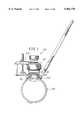
- FIG. 1is a side view of an internal keratome apparatus for forming a pocket between adjacent layers of a live cornea according to an embodiment of the present invention
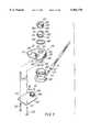
- FIG. 2is a cross-sectional view of the cornea holding apparatus of the internal keratome apparatus shown in FIG. 1 in relation to the cutting tool of the internal keratome apparatus;
- FIG. 3is an exploded perspective view of the cornea holding apparatus shown in FIGS. 1 and 2;
- FIG. 4is an exploded perspective view of the cutting tool shown in FIGS. 1 and 2;
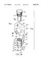
- FIG. 5is a top view of the internal keratome apparatus as taken along lines V--V in FIG. 1;
- FIG. 6is a front view of the internal keratome apparatus as taken along lines VI--VI in FIG. 5;
- FIG. 7is a bottom view of the internal keratome apparatus as taken along lines VII--VII in FIG. 6;
- FIG. 8is a front view of the cutting tool of the internal keratome apparatus shown in FIG. 1 as taken along lines VIII--VIII in FIG. 2;
- FIG. 9is a bottom view of the cutting tool as taken along lines IX--IX in FIG. 8;
- FIG. 10is a top view of the cutting tool as taken along lines X--X in FIG. 8;
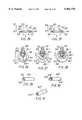
- FIG. 11is an enlarged view of the cutting portion of the blade of the cutting tool
- FIG. 12is a side view of the cutting portion of the blade as taken along lines XII--XII in FIG. 11;
- FIG. 13is another embodiment of the cutting portion of the blade of the cutting tool
- FIG. 14is a front view of the front portion of the live cornea in which adjacent layers are being separated by the cutting tool of the internal keratome apparatus according to the present invention
- FIG. 15is a front view of the front portion of the live cornea in which adjacent layers are being further separated by the cutting tool of the internal keratome apparatus according to the present invention
- FIG. 16is a front view of the front portion of the live cornea in which adjacent layers are being separated by the cutting tool of the internal keratome apparatus according to the present invention such that a circularly-shaped or substantially circularly-shaped pocket is formed between the adjacent layers of the live cornea;
- FIG. 17is a front view of the front portion of the live cornea in which the pocket formed in the live cornea as shown in FIG. 16 is expanded by the cutting tool to form a flap-like layer at the front portion of the live cornea;
- FIG. 18is an exploded perspective view of another embodiment of a cornea holding apparatus of an internal keratome apparatus according to the present invention.
- FIG. 19is a front view of the embodiment of the cornea holding apparatus shown in FIG. 18 as taken along lines XIX--XIX;
- FIG. 20a rear view of the embodiment of the cornea holding apparatus shown in FIG. 18 as taken along lines XX--XX;
- FIG. 21is a cross-sectional view of the cornea holding apparatus shown in FIGS. 18-20;
- FIG. 22is a top view of another embodiment of a cutting tool used of an internal keratome apparatus according to the present invention.
- FIG. 23is a side view of the embodiment of the cutting tool apparatus shown in FIG. 22 engaging with the cornea holding apparatus shown in FIGS. 18-21;
- FIG. 24is a view of the ring-like member of the cornea holding apparatus shown in FIGS. 18-21 and 23 as positioned in its lower position;
- FIG. 25is a view of the ring-like member of the cornea holding apparatus shown in FIGS. 18-21 and 23 as positioned in its upper position;
- FIG. 26is a view of the guide rails of the cutting tool apparatus shown in FIG. 22 engaging with the ring-like member of the cornea holding apparatus shown in FIGS. 18-21 and 23 when the blade is positioned at a first depth in the cornea;
- FIG. 27is a view of the guide rails of the cutting tool apparatus shown in FIG. 22 engaging with the ring-like member of the cornea holding apparatus shown in FIGS. 18-21 and 23 when the blade is positioned at a second depth in the cornea;
- FIG. 28is a view of the guide rails of the cutting tool apparatus shown in FIG. 22 engaging with the ring-like member of the cornea holding apparatus shown in FIGS. 18-21 and 23 when the blade is positioned at a third depth in the cornea;
- FIG. 29is a perspective view of an embodiment of an instrument for use in removing epithelial cells from the outer surface of a live cornea according to the present invention.
- FIG. 30is a perspective view of another embodiment of an instrument for use in removing epithelial cells from the outer surface of a live cornea according to the present invention.
- FIG. 31is a perspective view of a further embodiment of an instrument for use in removing epithelial cells from the outer surface of a live cornea according to the present invention.
- FIG. 1An embodiment of an apparatus for performing an internal keratome on a patient's live cornea is illustrated in FIG. 1.
- the apparatus 100includes a cornea holding apparatus 102 and a cutting tool 104.
- the corneal holding apparatus 102 and cutting tool 104are shown in more detail in FIGS. 2-13.
- the corneal holding apparatus 102includes a cornea receiving section 106 which receives a front portion of a live cornea 108 of a patient's eye as shown, for example, in FIG. 1.
- a tube 110having an opening 112 therein extending along the length thereof is coupled to the cornea receiving section 106 such that the opening 112 communicates with an interior cavity 114 of the cornea receiving section 106.
- the tube 110has a section 111 that is removably attached to a section 113 that is secured to or integral with the cornea receiving section 106.
- the section 113has a threaded portion 115 which engages with threads 117 on the interior of section 111 to couple sections 111 and 113 together.
- the interior surface of the cornea receiving section 106includes a plurality of steps or ridges 116 which contact the surface of the live cornea 108 and assist in stabilizing the cornea from movement when the cornea is received in the cornea receiving section 106. That is, as the front surface of the cornea 108 of the eye is received in the receiving section 106, suction will be applied via tube 110 to the internal cavity 114 of the receiving section 106 to suck the cornea into the cavity 114.
- the cornea receiving section 106further includes an opening 118. As shown, for example, in FIG. 1, a front portion 120 of the cornea 108 will protrude through the opening 118 when suction is applied to the cavity 114 of the cornea receiving section 106.
- the cornea holding apparatus 102further includes a flat or substantially flat plate 122 having an opening 124 therein.
- the opening 124is aligned with or substantially aligned with the opening 118 in the cornea receiving section 106.
- the front portion 120 of the corneawill protrude through the opening 118 in the section 106 and the opening 124 in the plate 122.
- the cornea holding apparatus 102further includes a clear or substantially clear viewer 126 that is mounted in a viewer holding section 128.
- the viewer 126is preferably a synthetic material, such as an acrylic, plexy glass, or the like, having threads which are as fine as possible.
- the viewer 126is permanently or removably mounted in the viewer holding section 128.
- the viewer holding section 128includes a threaded rotating portion 130 and a flat or substantially flat plate 132.
- the rotating portion 130is rotatable with respect to the view piece 126 and the plate 132 about an axis the same or substantially the same as the axis of the viewer 126.
- the outer surface of the rotating piece 130preferably has cross-hatching 134 to enable a user of the apparatus 102 to more easily grasp the outer surface of the rotating portion 130.
- the rotating portionfurther includes threading 136 on the inner surface thereof.
- the threading 136is adaptable to mate with threading 138 of the cornea receiving section 106 as shown specifically in FIG. 3.
- the viewer receiving section 128can be rotatably secured to the cornea receiving section 106 through the engagement of threads 136 and 138 as the rotating portion 130 is rotated onto the threaded portion 138.
- the plate 132further includes a cylindrical or substantially cylindrical section 140 having threads 142 on the interior surface thereof.
- the plate 122further includes a protruding section 144 having threads 146 which are adaptable to mate with the threads of the projecting portion 140.
- pins 125are adaptable to be inserted through openings 127 in the flat plate 122 and through hollow pins 129 and into openings 131 of the flat plate 132 so as to assist in coupling the flat plate 132 to the flat plate 122.
- flat plate 132includes an opening therein which has any shape suitable to accommodate the cutting tool 104 as will be discussed below.
- the cornea holding apparatus 102further includes a washer 148 made of rubber, synthetic, or the like, and a ring-like member 150 having threads 152 at a bottom portion thereof and an opening 154 therein.
- the threads 152are adaptable to mate with threads 133 in an opening 135 of the plate 132. Hence, when the ring-like member 150 is rotated when the threads 152 contact the threads 133, the ring-like member 150 is rotatably secured to the plate 132.
- the apparatus 102further includes a second ring-like member 156 made of synthetic, plastic, or the like.
- the second ring-like member 156has a protruding portion 158 having an opening 160 therein.
- the protruding portion 158is adaptable to be received in an opening 151 of the ring-like member 150 such that the opening 160 is positioned to align with or substantially align with the opening 154.
- the ring-like member 150includes a notch 153 that is adaptable to engage with an opening 161 in the protruding portion 158 of the second ring-like member 156.
- the second ring-like member 156further includes an opening 162 therein. Accordingly, as shown in FIG. 2 specifically, the opening 162, opening 151, an opening 149 in the washer 148, and the viewer 126 are aligned with or essentially aligned with each other so that the surface 120 of the cornea can be seen through the opening 162.
- all of the components of the cornea holding apparatus 102are made of metal, steel or the like. Naturally, all components of the cornea holding apparatus can be made of any suitable material as would be readily appreciated by one skilled in the art.
- the cutting tool 104includes a blade 180, a guiding device 182, and a flat plate 184.
- the blade 180, the guiding device 182 and the plate 184are coupled together, for example, by a screw 186, washer 188, washer 190, nut 192, washer 194, nut 196 and a handle 198 having cross-hatching thereon to enable its outer surface to be gripped more easily.
- the blade 180 and the guiding member 182are aligned or essentially aligned with each other.
- the cutting tool 104is removably attached to the cornea holding apparatus 102 such that the front end 183 of the guide member 182 is inserted through the opening 160 of the ring-like member 156 and through the opening 154 of the ring-like member 150. Furthermore, the front end 181 of the blade 180 is adaptable to be inserted between the bottom surface 127 of the viewer 126 and the top surface 123 of the flat plate 122.
- the blade 180, screw 186, washers 188 and 190, and nut 192are inserted through the opening 139 in the plate 132 as illustrated specifically in FIG. 2. Accordingly, when suction is applied to the cornea of the eye 108, the front surface 120 of the cornea is forced to protrude through the opening 118 in the receiving section 106 and the opening 124 and the flat plate 102 so that the cornea 120 contacts the bottom surface 127 of the viewer 126. Hence, the front surface 120 of the cornea will become flattened to a certain degree due to the contact with the surface 127 of the viewer 126.
- the front end 181 of the blade 180When layers of the live cornea are to be separated, the front end 181 of the blade 180 will be directed toward the protruding portion 120 of the cornea to be inserted into the protruding portion 120 and thus separate adjacent layers of the cornea 108 from each other. As shown in FIGS. 11 and 12 specifically, the front end portion 181 of the blade 180 is round or substantially round such that its diameter is about 4 mm. and is greater than the width of the blade and change "181" to 180.
- the blade 180can be any desired shape, such as star-shaped, petal shaped, oval, or the like, which can be adapted to form a circularly shaped or substantially circularly shaped pocket between the layers of the live cornea.
- the bladecan be made of any type of suitable material such as surgical steel, stainless steel or the like, and can have a diamond cutting edge.
- the cutting edge 183should be at the top surface of the portion 181.
- the top surface 185 and bottom surface 187 of the bladecan be parallel or substantially parallel with each other.
- the front portion 181can be slanted as indicated by 181'.
- the cutting edge 183' of the bladeis formed by the contact between the slanted surface 185' and the bottom surface 187 of the blade.
- the blade 180will be aligned with or substantially aligned with the guide member 182.
- the position of the guide member 180 with respect to the front surface of the protruding portion 120 of the live cornea that is being flattened by the bottom surface 127 of the viewer 126will correspond to or substantially correspond to the position of the blade 182 with respect to the protruding portion of the live cornea.
- a spring member 141which is integral or attached to the flat plate 122 will function to urge the blade 180 toward the top surface 123 of the plate 122.
- the bottom surface 187 of the blade 180will contact the top surface 123 of the plate 122 while the spring 141 contacts the top surface 185 of the blade 180.
- the cutting tool 102can then be moved to form a pocket between adjacent layers of the live cornea.
- the blade 180when the blade 180 is being inserted into the front surface 120 of the live cornea, an incision or separation 200 between adjacent layers of the live cornea will be formed. As the blade 180 is further inserted into the front surface 120 of the cornea, the spacing between the layers of the live cornea will be expanded to form a space 202 as shown in FIG. 15. The blade 180 can then be moved by twisting the handle 198 so that the blade 180 will reciprocate in a direction along arrow A. By moving the blade 180 in this reciprocating manner, the front portion of the blade 181 will form a circularly-shaped or substantially circularly-shaped pocket 206 in the front surface 120 of the cornea.
- the pocket 206can be made at any practical size as desired. Furthermore, the pocket 206 can be made at any practical depth in the front surface 120 of the live cornea.
- the depth at which the pocket will be formed in the cornea 108is governed by the distance between the top surface 185 of the blade 180 and the bottom surface 127 of the viewer 126. That is, since the thickness of the blade 180 is known, the distance between the bottom surface 127 of the viewer 126 and the top surface 123 of the flat plate 122 is set so that the cutting edge 183 of the blade will enter the front protruding portion 120 of the cornea at the desired distance from the front surface of the live cornea (i.e., at the desired depth into the live cornea).
- the distance between the bottom surface 127 of the viewer 126 and the top surface 123 of the plate 122can be adjusted when the viewer holding section 128 is being attached to the plate 122 in the manner discussed above. That is, the amount that the cylindrical portion 140 is screwed onto the protruding portion 144 as shown in FIG. 3 will determine the distance between the front surface 127 of the view-piece 126 and the top surface 123 of the plate 122. Hence, the cylindrical portion 140 will be threaded onto the protruding portion 144 to a degree that will space the front surface 127 of the viewer 126 from the top surface 123 of the plate 122 the desired distance.
- the range in which the guide member 182 will reciprocate along the direction indicated by arrow A in FIG. 5will be limited by the width of the opening 154 in ring member 150. That is, if the pocket 206 is to be made larger in a direction transverse to the extending direction of the blade 180, the width of the opening in ring member 150 will be larger to enable the guide member 182 to reciprocate along a larger arc in the direction defined by arrow A. Accordingly, because the blade 180 is aligned or substantially aligned with guide member 182, the blade will also be able to reciprocate along an arc in the direction defined by arrow A as limited by the width of the opening 154 in the ring-like member 150. Hence, different ring-like members having differently sized openings 154 can be used to adjust the size of the pocket 206 formed in the front portion 120 of the cornea.
- an implantsuch as those discussed above, can be placed inside the pocket to alter the curvature of the cornea.
- the distance along which the guide member 182 and hence, the blade 180, are allowed to reciprocatecan be increased to form this flap-like layer as shown, for example, in FIG. 17. That is, the guide member 182 can be allowed to reciprocate along an arc large enough to allow the cutting portion 181 of the blade 180 to pass through the sides of the front protruding portion 120 of the cornea as necessary so that the flap-like layer 208 is separated from the main portion of the live cornea except for a connecting portion 210.
- the flap-like layer 208will be capable of pivoting with respect to the remaining portion of the live cornea 108 about connecting portion 210 to expose a surface of the cornea underneath the flap-like layer 208. That exposed surface can be irradiated with a laser, for example, as described in U.S. Pat. No. 4,840,175 to Peyman, the entire contents of which are incorporated herein by reference. Also, a ring or disc can be placed on the exposed surface of the cornea and then covered by the flap-like layer 208 so that the shape of the ring or disc will influence the shape of the flap-like layer and hence, change the refractive power of the flap-like layer, thereby changing the focusing power of the eye.
- the pochetprior to forming the flap-like layer, protects the eye from losing aqueous humor if the blade 180 is inadvertently inserted too deep into the cornea so that it enters the anterior chamber of the eye. That is, because the pocket is only open on one end, as contrasted with a flap which is essentially separated from the cornea but for the connecting portion 210, the pocket will function to retain fluid in the anterior chamber and thus prevent against fluid loss better than would a flap-like member.
- the apparatus 300includes a cornea holding section 302, a body 304 and a viewer 306.
- the cornea holding section 302includes a cornea receiving section 308 having a cavity 310.
- a hollow tube 312 having an opening 314 along the length thereofis in communication with the cavity 310.
- the cornea holding apparatus 302further includes a flat plate 316 that is either attached to or integral with the cornea receiving section 310.
- a tubular extension 318extends in a direction away from the top surface 320 of the flat plate 316.
- the narrow section 319 of the tubular extension 318 adjacent to the top surface 320 of the flat plate 316has an opening 322 therein.
- the flat plate 316has an opening 317 therein which communicates with the cavity 310 of the cornea receiving section 308.
- the tubular extension 318further has a first wider section 324 having an outer diameter greater than that of the narrow section, and a second wider section 326 having an outer diameter greater than that of the first wider section 324.
- the second wider section 326has threading 328 along the inner circumference thereof.
- the tubular extension 318is hollow throughout so that the interior of the second wider section 326 is in communication with the interior of the first wider section 324, the interior of the narrow section 319, the opening 322 and the opening 317 in the flat plate 316. Hence, the interior of the tubular extension 318 is in communication with the cavity 310 of the cornea receiving section 308.
- a ring-like member 330is positioned about the tubular extension 318 and is coupled to a handle 332.
- the handle 332can be configured to move the ring-like member 330 down and up along the tubular extension 318 in the directions indicated by arrows B1 and B2, respectively.
- the opening 331 in the ring-like member 330will align or substantially align with the opening 322 in the tubular extension 318.
- the cornea holding section 302is received in an opening 340 of the body 304.
- the opening 340extends throughout the center of the body 304 such that the body will substantially encase the tubular member 318.
- a screw 342can be received in a threaded opening 344 in the body 304 to abut against the screw contacting surface 346 of the cornea receiving section 302 to thus removably secure the body 304 to the cornea receiving section 302.
- the body 304further includes recesses 348 which extend on opposite sides thereof as illustrated.
- the viewer 306is made of a synthetic material, such as acrylic or the like, and is transparent or substantially transparent to visible light.
- the viewer 306has threads 350 which engage with the threads 328 of the cornea receiving section 302 when the viewer 306 is inserted into the opening 340 of the body 304, and thus into the opening in the second wider section 326 of the tubular projection 318 as illustrated. Accordingly, the viewer 306 is threadedly engaged with the cornea receiving apparatus 302.
- the threads 352 on the viewer 306enable a user to grip the outer surface of the viewer 306 more firmly and thus, screw the viewer 306 into the tubular extension 318.
- FIGS. 21-28The operation of the apparatus 300 will now be described with reference to FIGS. 21-28, in particular.
- a cornea 108is received in the cornea receiving section 308 and suction is applied via tube 312 to the cavity 310, the cornea will be sucked into the cavity 310.
- a front portion 120 of the corneawill protrude through the opening 317 in the plate 316.
- the viewer 306will be adjusted so that the bottom surface 353 of the viewer contacts the front surface of the cornea 108 to flatten out the front surface of the front portion 120 of the cornea as illustrated.
- a tool 360 as shown in FIG. 22can be used.
- the tool 360includes a blade 180-1 having a cutting portion 181-1 as described above with regard to FIG. 11.
- the tool 360includes a motor which functions to move the blade 180-1 in a reciprocal motion along arrow A as illustrated.
- the bladecan also be shaped as the blades described above with regard to FIGS. 12 and 13, for example, and can be made of the materials described above.
- the blade 180-1has a top surface 185-1, a bottom surface 187-1, and a cutting edge 183-1, as shown in FIG. 12.
- the front portion 181'-1can be slanted, with the cutting edge 183'-1 formed by the contact between the slanted surface 185'-1 and bottom surface 187-1.
- the tool 360will be positioned so that the rails 362 of the tool 360 are positioned about the tubular extension 318. It is noted that a spring-like member 349 of the body 304 will press against the top surface 185-1 of the blade 180-1 when the blade 180-1 is being positioned as shown in FIG. 23 so that the bottom surface 187-1 of the blade will contact the top surface 320 of the plate 316.
- the cutting or separating of the layerscan then be performed as follows.
- the handle 332is positioned so that the ring-like member 330 moves in the direction B1 and becomes positioned to touch or substantially touch the top surface 320 of the plate 316 as shown in FIG. 24.
- the reciprocal motion of the blade 180 along the direction Ais limited by the contact of the inner surface 363 of the rails 362 and the outer surface 333 of the ring 330.
- the reciprocating toolcan include a guide 364 having guide rails 366 which each engage with the respective grooves 348 which are on opposite sides of the body 304 so as to assist in guiding the blade 180 in the direction D.
- the space 200 shown in FIG. 14will be formed.
- the space 202 between the layers of the cornea as shown in FIG. 15will be formed, and then the pocket 206 as shown in FIG. 16 will be formed.
- the reciprocal movement of the blade 180-1 in the direction Awill be limited more when the blade is positioned as shown in FIG. 26 than when the blade is positioned as shown in FIG. 27.
- the movement of the blade 180-1 in the reciprocal direction Awill be limited more due to the curvature of the rails 362 when the blade 180-1 is in the position as shown in FIG. 28 than when the blade 180-1 is in the position as shown in FIG. 27. Accordingly, a circularly-shaped pocket 206 as shown in FIG. 16 can be formed.
- the depth at which the blade 180-1 will cut into the corneais determined based on the distance between the bottom flat surface 353 of the viewer 306 and the top surface 320 of the plate 316. That is, taking into account the thickness of the blade 180-1, the viewer 306 can be screwed into the tubular extension 318 to a depth necessary so that the distance between the bottom surface 353 of the eye-piece and the top surface 320 of the plate 316 will position the blade 180-1 to enter into the cornea 108 at the desired depth from the front of the cornea 108 when the front of the cornea contacts the bottom surface 353 of the viewer 306.
- the ring 330 which restricts the reciprocating motion of the bladecan be lifted as shown in FIG. 25. That is, as discussed above, the handle 332 can be moved so that the ring-like member 330 will slide about the tubular extension 318 in the direction toward position B2. Hence, the inner surfaces 363 will no longer contact the outer surface 331 of the ring-like member 330. Rather, the movement of the blade 180-1 will be limited by the contact of the inner surfaces 363 of the rails 362 and the outer surface of the tubular extension 318.
- the movement of the blade 180-1will be less restricted in the direction A because the rails 362 will be allowed to move a greater direction along the direction A.
- the cutting portion 181-1 of the blade 180-1will cut through the sides of the front portion 120 of the cornea to form a flap-like layer 208 that is connected to the remainder of the cornea by a connection portion 210.
- the flap-like layer 208can be lifted to expose an inner surface of the cornea, and various techniques can be performed on that inner surface of the cornea.
- the blade 180-1when the blade 180-1 is inserted in the cornea 108, it may be necessary to remove corneal epithelium prior to performing the cutting so that the corneal epithelium cells do not become attached to the blade 180 and be forced by the blade between the adjacent layers of the cornea. In other words, it may be necessary to remove the corneal epithelium so that those cells do not become lodged in the pocket 206.
- an instrument 400 as shown in FIG. 29can be used.
- the instrument 400can be a tube-like structure having a hollow opening 402 therein in which is disposed a sponge 404 which is made of rubber or the like.
- the inner diameter of the tubecan be, for example, about 1-12 millimeters. If it is determined desirable to remove the corneal epithelium cells prior to performing the cutting or layer separating operation discussed above, the end of the instrument 400 in which the sponge 404 is disposed can be dipped into an alcohol mixture so that the alcohol mixture will become absorbed in the sponge 404. The end of the instrument 400 having the sponge 404 can then be dabbed onto the front portion 120 of the cornea that is to be cut, thus eliminating the epithelium cells.
- the time for which the instrument 400 must be applied to the front portion 120 of the corneadepends on the concentration of the alcohol in the mixture.
- the instrument 400need not be tubular, but rather, can be arcuate in shape (see FIG. 30) or rectangular or square (see FIG. 31). If the instrument is arcuately-shaped, the diameter D should be about 1-12 millimeters, and the sponge 404' will be inserted between the outer wall 406' and inner wall 408' of the arcuately-shaped instrument 400'. If the square or rectangularly-shaped instrument 400" is used, the sponge 404" also will have a similar shape. If the time at which the instruments 400' or 400" will be applied to the front portion 120 of the cornea prior to cutting the front portion of the cornea will be the same as illustrated in Table 1 depending on the concentration of the alcohol mixture used. Accordingly, the instruments shown in FIGS. 29-31 will prevent the epithelium cells from becoming lodged between the layers of the cornea when the pocket 206 or flap 208, as shown in FIGS. 16 and 17, respectively, are formed by insertion of the blade 180 into the cornea.
Landscapes
- Health & Medical Sciences (AREA)
- Ophthalmology & Optometry (AREA)
- Heart & Thoracic Surgery (AREA)
- Surgery (AREA)
- Engineering & Computer Science (AREA)
- Biomedical Technology (AREA)
- Nuclear Medicine, Radiotherapy & Molecular Imaging (AREA)
- Vascular Medicine (AREA)
- Life Sciences & Earth Sciences (AREA)
- Animal Behavior & Ethology (AREA)
- General Health & Medical Sciences (AREA)
- Public Health (AREA)
- Veterinary Medicine (AREA)
- Prostheses (AREA)
Abstract
Description
TABLE 1 ______________________________________ Alcohol Concentration Duration of Application of Instrument ______________________________________ 50 percent 10 seconds 30 percent 15 seconds 20 percent 20 seconds 15 percent 30 seconds 10 percent 45 seconds ______________________________________
Claims (27)
Priority Applications (2)
| Application Number | Priority Date | Filing Date | Title |
|---|---|---|---|
| US08/936,509US5964776A (en) | 1997-09-24 | 1997-09-24 | Internal keratome apparatus and method for using the same to form a pocket/flap between layers of a live cornea |
| US09/384,368US20010004702A1 (en) | 1997-09-24 | 1999-08-27 | Internal keratome apparatus and method for using the same to form a pocket/flap between layers of a live cornea |
Applications Claiming Priority (1)
| Application Number | Priority Date | Filing Date | Title |
|---|---|---|---|
| US08/936,509US5964776A (en) | 1997-09-24 | 1997-09-24 | Internal keratome apparatus and method for using the same to form a pocket/flap between layers of a live cornea |
Related Child Applications (1)
| Application Number | Title | Priority Date | Filing Date |
|---|---|---|---|
| US09/384,368DivisionUS20010004702A1 (en) | 1997-09-24 | 1999-08-27 | Internal keratome apparatus and method for using the same to form a pocket/flap between layers of a live cornea |
Publications (1)
| Publication Number | Publication Date |
|---|---|
| US5964776Atrue US5964776A (en) | 1999-10-12 |
Family
ID=25468746
Family Applications (2)
| Application Number | Title | Priority Date | Filing Date |
|---|---|---|---|
| US08/936,509Expired - LifetimeUS5964776A (en) | 1997-09-24 | 1997-09-24 | Internal keratome apparatus and method for using the same to form a pocket/flap between layers of a live cornea |
| US09/384,368AbandonedUS20010004702A1 (en) | 1997-09-24 | 1999-08-27 | Internal keratome apparatus and method for using the same to form a pocket/flap between layers of a live cornea |
Family Applications After (1)
| Application Number | Title | Priority Date | Filing Date |
|---|---|---|---|
| US09/384,368AbandonedUS20010004702A1 (en) | 1997-09-24 | 1999-08-27 | Internal keratome apparatus and method for using the same to form a pocket/flap between layers of a live cornea |
Country Status (1)
| Country | Link |
|---|---|
| US (2) | US5964776A (en) |
Cited By (73)
| Publication number | Priority date | Publication date | Assignee | Title |
|---|---|---|---|---|
| US6059805A (en)* | 1998-03-31 | 2000-05-09 | Nidek Co., Ltd. | Corneal surgical apparatus |
| US6203555B1 (en)* | 1999-03-03 | 2001-03-20 | Nidek Co., Ltd | Corneal surgical apparatus |
| US6254619B1 (en) | 1999-12-28 | 2001-07-03 | Antoine Garabet | Microkeratome |
| US6350272B1 (en) | 2000-03-20 | 2002-02-26 | Glenn Kawesch | Method and apparatus for cutting an oblong corneal flap |
| EP1186281A1 (en)* | 2000-09-08 | 2002-03-13 | Luigi Olivieri | Apparatus for corneal surgery |
| US6358262B1 (en) | 1999-11-05 | 2002-03-19 | Alcon Universal Ltd. | Lamellar dissecting instrument |
| US6358261B1 (en) | 1999-11-05 | 2002-03-19 | Alcon Universal Ltd. | Lamellar dissecting instrument |
| US6436113B1 (en)* | 2000-09-18 | 2002-08-20 | Thomas A. Burba | Eye positioner |
| WO2002076320A1 (en)* | 2001-03-23 | 2002-10-03 | Gholam Peyman | Adjustable ablatable inlay |
| US20030130676A1 (en)* | 2001-12-12 | 2003-07-10 | Nidek Co., Ltd. | Blade for corneal surgery and corneal surgical apparatus comprising the same |
| US6599305B1 (en)* | 1998-08-12 | 2003-07-29 | Vladimir Feingold | Intracorneal lens placement method and apparatus |
| US20040243159A1 (en)* | 2003-05-27 | 2004-12-02 | Yichieh Shiuey | System for cutting the cornea of an eye |
| US6855163B2 (en) | 2002-07-19 | 2005-02-15 | Minu, Llc | Gradual correction of corneal refractive error using multiple inlays |
| US20050143717A1 (en)* | 2001-04-27 | 2005-06-30 | Peyman Gholam A. | Method of treatment of refractive errors using subepithelial or intrastromal corneal inlay with bonding coating |
| US20050182488A1 (en)* | 2001-04-27 | 2005-08-18 | Peyman Gholam A. | Implant and method for altering the refractive properties of the eye |
| US20050182489A1 (en)* | 2001-04-27 | 2005-08-18 | Peyman Gholam A. | Intraocular lens adapted for adjustment via laser after implantation |
| US20050178394A1 (en)* | 2003-08-21 | 2005-08-18 | Intralens Vision, Inc. | Method for keratophakia surgery |
| US20050222679A1 (en)* | 2001-04-27 | 2005-10-06 | Peyman Gholam A | Bifocal implant and method for altering the refractive properties of the eye |
| WO2005115283A1 (en)* | 2004-05-26 | 2005-12-08 | Wuxi Kangming Medical Device Co., Ltd. | Automatic cornea epithelium separating apparatus |
| US6989008B2 (en) | 2001-03-23 | 2006-01-24 | Minu Llc | Adjustable ablatable inlay |
| US20060287663A1 (en)* | 2005-06-15 | 2006-12-21 | Gayheart Robert A | Corneal excision or scoring device |
| US20070016234A1 (en)* | 2003-05-02 | 2007-01-18 | Albert Daxer | Device for cutting the cornea of an eye |
| US7166117B2 (en) | 1996-02-07 | 2007-01-23 | Hellenkamp Johann F | Automatic surgical device and control assembly for cutting a cornea |
| EP1757254A3 (en)* | 2005-08-24 | 2007-05-16 | Wavelight Laser Technologie AG | Microsurgical cutting instrument for use in refractive eye surgery |
| USD546452S1 (en) | 2005-06-15 | 2007-07-10 | Krishna Imports, Incorporated | Excision device |
| JP2008504898A (en)* | 2004-07-01 | 2008-02-21 | バイオヴィジョン アーゲー | Intracorneal lens placement method and apparatus |
| US20090004636A1 (en)* | 2007-06-28 | 2009-01-01 | Eye Care And Cure Corp. | Model human eye |
| US20090004637A1 (en)* | 2007-06-28 | 2009-01-01 | Eye Care And Cure Corp. | Model human eye |
| US20090076601A1 (en)* | 2006-03-16 | 2009-03-19 | Albert Daxer | Cornea Implant |
| US20090240327A1 (en)* | 2006-05-23 | 2009-09-24 | Albert Daxer | Corneal Implant and Method for Correction of Impaired Vision in the Human Eye |
| US7628810B2 (en) | 2003-05-28 | 2009-12-08 | Acufocus, Inc. | Mask configured to maintain nutrient transport without producing visible diffraction patterns |
| US7776086B2 (en) | 2004-04-30 | 2010-08-17 | Revision Optics, Inc. | Aspherical corneal implant |
| US7780689B2 (en) | 2003-04-07 | 2010-08-24 | Technolas Perfect Vision Gmbh | Bar-link drive system for a microkeratome |
| US20100318017A1 (en)* | 2009-06-11 | 2010-12-16 | Lewis Scott E | Method of improving vision using contact lenses and corneal collagen crosslinking |
| US20110098790A1 (en)* | 2009-10-26 | 2011-04-28 | Albert Daxer | Methods for treating corneal disease |
| US7976577B2 (en) | 2005-04-14 | 2011-07-12 | Acufocus, Inc. | Corneal optic formed of degradation resistant polymer |
| US8057541B2 (en) | 2006-02-24 | 2011-11-15 | Revision Optics, Inc. | Method of using small diameter intracorneal inlays to treat visual impairment |
| US8079706B2 (en) | 2003-06-17 | 2011-12-20 | Acufocus, Inc. | Method and apparatus for aligning a mask with the visual axis of an eye |
| USD656526S1 (en) | 2009-11-10 | 2012-03-27 | Acufocus, Inc. | Ocular mask |
| US8162953B2 (en) | 2007-03-28 | 2012-04-24 | Revision Optics, Inc. | Insertion system for corneal implants |
| US8343215B2 (en) | 1999-03-01 | 2013-01-01 | Acufocus, Inc. | System and method for increasing the depth of focus of the human eye |
| US8469948B2 (en) | 2010-08-23 | 2013-06-25 | Revision Optics, Inc. | Methods and devices for forming corneal channels |
| US8668735B2 (en) | 2000-09-12 | 2014-03-11 | Revision Optics, Inc. | Corneal implant storage and delivery devices |
| US8684743B2 (en) | 2010-07-23 | 2014-04-01 | Eye Care And Cure Pte. Ltd | Model human eye and face manikin for use therewith |
| US8900296B2 (en) | 2007-04-20 | 2014-12-02 | Revision Optics, Inc. | Corneal inlay design and methods of correcting vision |
| US9005280B2 (en) | 2000-09-12 | 2015-04-14 | Revision Optics, Inc. | System for packaging and handling an implant and method of use |
| US9005281B2 (en) | 2009-08-13 | 2015-04-14 | Acufocus, Inc. | Masked intraocular implants and lenses |
| US20150127041A1 (en)* | 2009-08-07 | 2015-05-07 | Ulthera, Inc. | Handpiece for use in tissue dissection |
| US9204962B2 (en) | 2013-03-13 | 2015-12-08 | Acufocus, Inc. | In situ adjustable optical mask |
| US9272124B2 (en) | 2005-12-02 | 2016-03-01 | Ulthera, Inc. | Systems and devices for selective cell lysis and methods of using same |
| US9271828B2 (en) | 2007-03-28 | 2016-03-01 | Revision Optics, Inc. | Corneal implant retaining devices and methods of use |
| US9345569B2 (en) | 2011-10-21 | 2016-05-24 | Revision Optics, Inc. | Corneal implant storage and delivery devices |
| US9358064B2 (en) | 2009-08-07 | 2016-06-07 | Ulthera, Inc. | Handpiece and methods for performing subcutaneous surgery |
| US9358033B2 (en) | 2005-09-07 | 2016-06-07 | Ulthera, Inc. | Fluid-jet dissection system and method for reducing the appearance of cellulite |
| US9427922B2 (en) | 2013-03-14 | 2016-08-30 | Acufocus, Inc. | Process for manufacturing an intraocular lens with an embedded mask |
| US9427311B2 (en) | 2009-08-13 | 2016-08-30 | Acufocus, Inc. | Corneal inlay with nutrient transport structures |
| US9539143B2 (en) | 2008-04-04 | 2017-01-10 | Revision Optics, Inc. | Methods of correcting vision |
| US9545303B2 (en) | 2011-12-02 | 2017-01-17 | Acufocus, Inc. | Ocular mask having selective spectral transmission |
| US9549848B2 (en) | 2007-03-28 | 2017-01-24 | Revision Optics, Inc. | Corneal implant inserters and methods of use |
| CN106420161A (en)* | 2016-10-17 | 2017-02-22 | 南京市第医院 | Multifunctional alcohol storage tank for PRK |
| US9943403B2 (en) | 2014-11-19 | 2018-04-17 | Acufocus, Inc. | Fracturable mask for treating presbyopia |
| US10004593B2 (en) | 2009-08-13 | 2018-06-26 | Acufocus, Inc. | Intraocular lens with elastic mask |
| US10220122B2 (en) | 2007-10-09 | 2019-03-05 | Ulthera, Inc. | System for tissue dissection and aspiration |
| US10531888B2 (en) | 2009-08-07 | 2020-01-14 | Ulthera, Inc. | Methods for efficiently reducing the appearance of cellulite |
| US10548659B2 (en) | 2006-01-17 | 2020-02-04 | Ulthera, Inc. | High pressure pre-burst for improved fluid delivery |
| US10555805B2 (en) | 2006-02-24 | 2020-02-11 | Rvo 2.0, Inc. | Anterior corneal shapes and methods of providing the shapes |
| US10583041B2 (en) | 2015-03-12 | 2020-03-10 | RVO 2.0 Inc. | Methods of correcting vision |
| US10687935B2 (en) | 2015-10-05 | 2020-06-23 | Acufocus, Inc. | Methods of molding intraocular lenses |
| US10835371B2 (en) | 2004-04-30 | 2020-11-17 | Rvo 2.0, Inc. | Small diameter corneal inlay methods |
| US11096708B2 (en) | 2009-08-07 | 2021-08-24 | Ulthera, Inc. | Devices and methods for performing subcutaneous surgery |
| US11337725B2 (en) | 2009-08-07 | 2022-05-24 | Ulthera, Inc. | Handpieces for tissue treatment |
| US11364110B2 (en) | 2018-05-09 | 2022-06-21 | Acufocus, Inc. | Intraocular implant with removable optic |
| US11464625B2 (en) | 2015-11-24 | 2022-10-11 | Acufocus, Inc. | Toric small aperture intraocular lens with extended depth of focus |
Families Citing this family (4)
| Publication number | Priority date | Publication date | Assignee | Title |
|---|---|---|---|---|
| JP2001095833A (en)* | 1999-09-30 | 2001-04-10 | Nidek Co Ltd | Coanea surgery device |
| WO2006019893A2 (en)* | 2004-07-15 | 2006-02-23 | Coopervision, Inc. | Intrastromal devices and method for improving vision |
| US20080281341A1 (en)* | 2007-05-11 | 2008-11-13 | Ension, Inc. | Apparatus and method for endothelial keratoplasty donor tissue transport and delivery |
| CN102365066B (en)* | 2009-02-20 | 2014-11-26 | 阿尔贝特·达克瑟尔 | Device for cutting the cornea of an eye |
Citations (25)
| Publication number | Priority date | Publication date | Assignee | Title |
|---|---|---|---|---|
| US3074407A (en)* | 1956-09-17 | 1963-01-22 | Marguerite Barr Moon Eye Res F | Surgical devices for keratoplasty and methods thereof |
| SU448013A1 (en)* | 1973-05-30 | 1974-10-30 | Б. Н. Алексеев | Tissue Delaminating Device |
| US4298004A (en)* | 1979-02-27 | 1981-11-03 | Schachar Ronald A | Surgical method for altering the curvature of the cornea of rabbits |
| DE3433581A1 (en)* | 1984-09-13 | 1986-03-20 | Fa. Carl Zeiss, 7920 Heidenheim | DEVICE FOR LAMINATING, REFRACTIVE CORNEAL SURGERY |
| US4648400A (en)* | 1985-05-06 | 1987-03-10 | Rts Laboratories, Inc. | Ophthalmic surgery system |
| US4676790A (en)* | 1985-09-25 | 1987-06-30 | Kern Seymour P | Method of manufacture and implantation of corneal inlays |
| US4718418A (en)* | 1983-11-17 | 1988-01-12 | Lri L.P. | Apparatus for ophthalmological surgery |
| US4796623A (en)* | 1987-07-20 | 1989-01-10 | The Cooper Companies, Inc. | Corneal vacuum trephine system |
| US4840175A (en)* | 1986-12-24 | 1989-06-20 | Peyman Gholam A | Method for modifying corneal curvature |
| US4903695A (en)* | 1988-11-30 | 1990-02-27 | Lri L.P. | Method and apparatus for performing a keratomileusis or the like operation |
| SU1660698A1 (en)* | 1989-04-13 | 1991-07-07 | Всесоюзный Научно-Исследовательский Институт Глазных Болезней | Myopia correction method |
| GB2242835A (en)* | 1990-04-26 | 1991-10-16 | Ahmed Salih Mahmud | Surgical knife |
| US5063942A (en)* | 1989-12-14 | 1991-11-12 | Corneal Contouring, Inc. | Method for surgically re-profiling the cornea |
| US5092874A (en)* | 1990-05-07 | 1992-03-03 | Rogers James C | Penetrating keratoplasty trephination press |
| US5203865A (en)* | 1990-08-23 | 1993-04-20 | Siepser Steven B | Surgical knives for use in ophthalmic surgery |
| US5215104A (en)* | 1988-08-16 | 1993-06-01 | Steinert Roger F | Method for corneal modification |
| WO1993020763A1 (en)* | 1992-04-10 | 1993-10-28 | Keravision Inc. | Corneal vacuum centering guide and dissector |
| US5290301A (en)* | 1991-09-10 | 1994-03-01 | Lieberman David M | Cam guided corneal trephine |
| US5318044A (en)* | 1989-12-14 | 1994-06-07 | Corneal Contouring, Inc. | Method and apparatus for re-profiling the cornea to correct for hyperopia |
| US5318046A (en)* | 1992-09-23 | 1994-06-07 | Rozakis George W | Method for corneal reprofiling |
| US5368604A (en)* | 1989-12-14 | 1994-11-29 | Corneal Contouring Inc. | Method and apparatus for surgically profiling the cornea using vacuum |
| US5496339A (en)* | 1994-05-17 | 1996-03-05 | Koepnick; Russell G. | Universal automated keratectomy apparatus and method |
| US5507741A (en)* | 1983-11-17 | 1996-04-16 | L'esperance, Jr.; Francis A. | Ophthalmic method for laser surgery of the cornea |
| US5507759A (en)* | 1994-01-14 | 1996-04-16 | Nordan; Lee T. | Variable resection keratoplasty method |
| US5843105A (en)* | 1994-01-07 | 1998-12-01 | Keravision Inc | System for inserting material into corneal stroma |
- 1997
- 1997-09-24USUS08/936,509patent/US5964776A/ennot_activeExpired - Lifetime
- 1999
- 1999-08-27USUS09/384,368patent/US20010004702A1/ennot_activeAbandoned
Patent Citations (28)
| Publication number | Priority date | Publication date | Assignee | Title |
|---|---|---|---|---|
| US3074407A (en)* | 1956-09-17 | 1963-01-22 | Marguerite Barr Moon Eye Res F | Surgical devices for keratoplasty and methods thereof |
| SU448013A1 (en)* | 1973-05-30 | 1974-10-30 | Б. Н. Алексеев | Tissue Delaminating Device |
| US4298004A (en)* | 1979-02-27 | 1981-11-03 | Schachar Ronald A | Surgical method for altering the curvature of the cornea of rabbits |
| US5507741A (en)* | 1983-11-17 | 1996-04-16 | L'esperance, Jr.; Francis A. | Ophthalmic method for laser surgery of the cornea |
| US4718418A (en)* | 1983-11-17 | 1988-01-12 | Lri L.P. | Apparatus for ophthalmological surgery |
| DE3433581A1 (en)* | 1984-09-13 | 1986-03-20 | Fa. Carl Zeiss, 7920 Heidenheim | DEVICE FOR LAMINATING, REFRACTIVE CORNEAL SURGERY |
| US4662370A (en)* | 1984-09-13 | 1987-05-05 | Carl-Zeiss-Stiftung | Apparatus for performing lamellar refractive corneal surgery |
| US4648400A (en)* | 1985-05-06 | 1987-03-10 | Rts Laboratories, Inc. | Ophthalmic surgery system |
| US4676790A (en)* | 1985-09-25 | 1987-06-30 | Kern Seymour P | Method of manufacture and implantation of corneal inlays |
| US4840175A (en)* | 1986-12-24 | 1989-06-20 | Peyman Gholam A | Method for modifying corneal curvature |
| US4796623A (en)* | 1987-07-20 | 1989-01-10 | The Cooper Companies, Inc. | Corneal vacuum trephine system |
| US5215104A (en)* | 1988-08-16 | 1993-06-01 | Steinert Roger F | Method for corneal modification |
| US4903695A (en)* | 1988-11-30 | 1990-02-27 | Lri L.P. | Method and apparatus for performing a keratomileusis or the like operation |
| US4903695C1 (en)* | 1988-11-30 | 2001-09-11 | Lri L P | Method and apparatus for performing a keratomileusis or the like operation |
| SU1660698A1 (en)* | 1989-04-13 | 1991-07-07 | Всесоюзный Научно-Исследовательский Институт Глазных Болезней | Myopia correction method |
| US5368604A (en)* | 1989-12-14 | 1994-11-29 | Corneal Contouring Inc. | Method and apparatus for surgically profiling the cornea using vacuum |
| US5318044A (en)* | 1989-12-14 | 1994-06-07 | Corneal Contouring, Inc. | Method and apparatus for re-profiling the cornea to correct for hyperopia |
| US5063942A (en)* | 1989-12-14 | 1991-11-12 | Corneal Contouring, Inc. | Method for surgically re-profiling the cornea |
| GB2242835A (en)* | 1990-04-26 | 1991-10-16 | Ahmed Salih Mahmud | Surgical knife |
| US5092874A (en)* | 1990-05-07 | 1992-03-03 | Rogers James C | Penetrating keratoplasty trephination press |
| US5203865A (en)* | 1990-08-23 | 1993-04-20 | Siepser Steven B | Surgical knives for use in ophthalmic surgery |
| US5290301A (en)* | 1991-09-10 | 1994-03-01 | Lieberman David M | Cam guided corneal trephine |
| WO1993020763A1 (en)* | 1992-04-10 | 1993-10-28 | Keravision Inc. | Corneal vacuum centering guide and dissector |
| US5403335A (en)* | 1992-04-10 | 1995-04-04 | Keravision, Inc. | Corneal vacuum centering guide and dissector |
| US5318046A (en)* | 1992-09-23 | 1994-06-07 | Rozakis George W | Method for corneal reprofiling |
| US5843105A (en)* | 1994-01-07 | 1998-12-01 | Keravision Inc | System for inserting material into corneal stroma |
| US5507759A (en)* | 1994-01-14 | 1996-04-16 | Nordan; Lee T. | Variable resection keratoplasty method |
| US5496339A (en)* | 1994-05-17 | 1996-03-05 | Koepnick; Russell G. | Universal automated keratectomy apparatus and method |
Non-Patent Citations (2)
| Title |
|---|
| Gerge J. Pardos, M.D., "Attention to detail is crucial in performing LASIK", 1995, Oscular Surgery News pp. 38-41. |
| Gerge J. Pardos, M.D., Attention to detail is crucial in performing LASIK , 1995, Oscular Surgery News pp. 38 41.* |
Cited By (129)
| Publication number | Priority date | Publication date | Assignee | Title |
|---|---|---|---|---|
| US7166117B2 (en) | 1996-02-07 | 2007-01-23 | Hellenkamp Johann F | Automatic surgical device and control assembly for cutting a cornea |
| US6059805A (en)* | 1998-03-31 | 2000-05-09 | Nidek Co., Ltd. | Corneal surgical apparatus |
| US6599305B1 (en)* | 1998-08-12 | 2003-07-29 | Vladimir Feingold | Intracorneal lens placement method and apparatus |
| US8752958B2 (en) | 1999-03-01 | 2014-06-17 | Boston Innovative Optics, Inc. | System and method for increasing the depth of focus of the human eye |
| US8343215B2 (en) | 1999-03-01 | 2013-01-01 | Acufocus, Inc. | System and method for increasing the depth of focus of the human eye |
| US6203555B1 (en)* | 1999-03-03 | 2001-03-20 | Nidek Co., Ltd | Corneal surgical apparatus |
| US6344046B2 (en)* | 1999-03-03 | 2002-02-05 | Nidek Co., Ltd | Corneal surgical apparatus |
| US6358262B1 (en) | 1999-11-05 | 2002-03-19 | Alcon Universal Ltd. | Lamellar dissecting instrument |
| US6358261B1 (en) | 1999-11-05 | 2002-03-19 | Alcon Universal Ltd. | Lamellar dissecting instrument |
| US6254619B1 (en) | 1999-12-28 | 2001-07-03 | Antoine Garabet | Microkeratome |
| US6350272B1 (en) | 2000-03-20 | 2002-02-26 | Glenn Kawesch | Method and apparatus for cutting an oblong corneal flap |
| US6716227B2 (en)* | 2000-09-08 | 2004-04-06 | Meditekno S.R.L. | Apparatus and method for corneal surgery |
| EP1186281A1 (en)* | 2000-09-08 | 2002-03-13 | Luigi Olivieri | Apparatus for corneal surgery |
| US9005280B2 (en) | 2000-09-12 | 2015-04-14 | Revision Optics, Inc. | System for packaging and handling an implant and method of use |
| US9889000B2 (en) | 2000-09-12 | 2018-02-13 | Revision Optics, Inc. | Corneal implant applicators |
| US8668735B2 (en) | 2000-09-12 | 2014-03-11 | Revision Optics, Inc. | Corneal implant storage and delivery devices |
| US6436113B1 (en)* | 2000-09-18 | 2002-08-20 | Thomas A. Burba | Eye positioner |
| US6989008B2 (en) | 2001-03-23 | 2006-01-24 | Minu Llc | Adjustable ablatable inlay |
| WO2002076320A1 (en)* | 2001-03-23 | 2002-10-03 | Gholam Peyman | Adjustable ablatable inlay |
| US20050143717A1 (en)* | 2001-04-27 | 2005-06-30 | Peyman Gholam A. | Method of treatment of refractive errors using subepithelial or intrastromal corneal inlay with bonding coating |
| US20050182488A1 (en)* | 2001-04-27 | 2005-08-18 | Peyman Gholam A. | Implant and method for altering the refractive properties of the eye |
| US20050182489A1 (en)* | 2001-04-27 | 2005-08-18 | Peyman Gholam A. | Intraocular lens adapted for adjustment via laser after implantation |
| US20050222679A1 (en)* | 2001-04-27 | 2005-10-06 | Peyman Gholam A | Bifocal implant and method for altering the refractive properties of the eye |
| US20030130676A1 (en)* | 2001-12-12 | 2003-07-10 | Nidek Co., Ltd. | Blade for corneal surgery and corneal surgical apparatus comprising the same |
| US7135028B2 (en) | 2001-12-12 | 2006-11-14 | Nidek Co., Ltd. | Blade for corneal surgery and corneal surgical apparatus comprising the same |
| US6855163B2 (en) | 2002-07-19 | 2005-02-15 | Minu, Llc | Gradual correction of corneal refractive error using multiple inlays |
| US7780689B2 (en) | 2003-04-07 | 2010-08-24 | Technolas Perfect Vision Gmbh | Bar-link drive system for a microkeratome |
| US20070016234A1 (en)* | 2003-05-02 | 2007-01-18 | Albert Daxer | Device for cutting the cornea of an eye |
| US7922735B2 (en)* | 2003-05-02 | 2011-04-12 | Albert Daxer | Device for cutting the cornea of an eye |
| US20040243160A1 (en)* | 2003-05-27 | 2004-12-02 | Yichieh Shiuey, M.D. | System for cutting the cornea of an eye |
| US7223275B2 (en) | 2003-05-27 | 2007-05-29 | Yichieh Shiuey | System for cutting the cornea of an eye |
| US7901421B2 (en)* | 2003-05-27 | 2011-03-08 | Yichieh Shiuey | System for cutting the cornea of an eye |
| US20040243159A1 (en)* | 2003-05-27 | 2004-12-02 | Yichieh Shiuey | System for cutting the cornea of an eye |
| JP4859669B2 (en)* | 2003-05-27 | 2012-01-25 | イッチエ シウイ | System for incising the cornea of the eye |
| WO2004105585A2 (en) | 2003-05-27 | 2004-12-09 | Yichieh Shiuey | System for cutting the cornea of an eye |
| US8858624B2 (en) | 2003-05-28 | 2014-10-14 | Acufocus, Inc. | Method for increasing the depth of focus of a patient |
| US10869752B2 (en) | 2003-05-28 | 2020-12-22 | Acufocus, Inc. | Mask for increasing depth of focus |
| US7628810B2 (en) | 2003-05-28 | 2009-12-08 | Acufocus, Inc. | Mask configured to maintain nutrient transport without producing visible diffraction patterns |
| US8460374B2 (en) | 2003-05-28 | 2013-06-11 | Acufocus, Inc. | Mask configured to maintain nutrient transport without producing visible diffraction patterns |
| US9138142B2 (en) | 2003-05-28 | 2015-09-22 | Acufocus, Inc. | Masked intraocular devices |
| US8864824B2 (en) | 2003-06-17 | 2014-10-21 | Acufocus, Inc. | Method and apparatus for aligning a mask with the visual axis of an eye |
| US8079706B2 (en) | 2003-06-17 | 2011-12-20 | Acufocus, Inc. | Method and apparatus for aligning a mask with the visual axis of an eye |
| US20050178394A1 (en)* | 2003-08-21 | 2005-08-18 | Intralens Vision, Inc. | Method for keratophakia surgery |
| US7776086B2 (en) | 2004-04-30 | 2010-08-17 | Revision Optics, Inc. | Aspherical corneal implant |
| US10835371B2 (en) | 2004-04-30 | 2020-11-17 | Rvo 2.0, Inc. | Small diameter corneal inlay methods |
| WO2005115283A1 (en)* | 2004-05-26 | 2005-12-08 | Wuxi Kangming Medical Device Co., Ltd. | Automatic cornea epithelium separating apparatus |
| US20080077166A1 (en)* | 2004-05-26 | 2008-03-27 | Renyuan Chu | Automatic Cornea Epithelium Separating Apparatus |
| JP2008504898A (en)* | 2004-07-01 | 2008-02-21 | バイオヴィジョン アーゲー | Intracorneal lens placement method and apparatus |
| US7976577B2 (en) | 2005-04-14 | 2011-07-12 | Acufocus, Inc. | Corneal optic formed of degradation resistant polymer |
| US8287592B2 (en) | 2005-04-14 | 2012-10-16 | Acufocus, Inc. | Ophthalmic devices having a degradation resistant polymer |
| US7744614B2 (en) | 2005-06-15 | 2010-06-29 | Krishna Imports, Incorporated | Corneal excision or scoring device |
| US20060287663A1 (en)* | 2005-06-15 | 2006-12-21 | Gayheart Robert A | Corneal excision or scoring device |
| USD546452S1 (en) | 2005-06-15 | 2007-07-10 | Krishna Imports, Incorporated | Excision device |
| WO2007104346A1 (en)* | 2005-08-24 | 2007-09-20 | Wavelight Ag | Microsurgical cutting instrument for refractive ophthalmological treatments |
| EP1757254A3 (en)* | 2005-08-24 | 2007-05-16 | Wavelight Laser Technologie AG | Microsurgical cutting instrument for use in refractive eye surgery |
| US9358033B2 (en) | 2005-09-07 | 2016-06-07 | Ulthera, Inc. | Fluid-jet dissection system and method for reducing the appearance of cellulite |
| US9364246B2 (en) | 2005-09-07 | 2016-06-14 | Ulthera, Inc. | Dissection handpiece and method for reducing the appearance of cellulite |
| US9272124B2 (en) | 2005-12-02 | 2016-03-01 | Ulthera, Inc. | Systems and devices for selective cell lysis and methods of using same |
| US10548659B2 (en) | 2006-01-17 | 2020-02-04 | Ulthera, Inc. | High pressure pre-burst for improved fluid delivery |
| US8057541B2 (en) | 2006-02-24 | 2011-11-15 | Revision Optics, Inc. | Method of using small diameter intracorneal inlays to treat visual impairment |
| US10555805B2 (en) | 2006-02-24 | 2020-02-11 | Rvo 2.0, Inc. | Anterior corneal shapes and methods of providing the shapes |
| US8377121B2 (en) | 2006-03-16 | 2013-02-19 | Albert Daxer | Cornea implant |
| US8092526B2 (en) | 2006-03-16 | 2012-01-10 | Albert Daxer | Cornea implant |
| US20090076601A1 (en)* | 2006-03-16 | 2009-03-19 | Albert Daxer | Cornea Implant |
| US20090240327A1 (en)* | 2006-05-23 | 2009-09-24 | Albert Daxer | Corneal Implant and Method for Correction of Impaired Vision in the Human Eye |
| US9510938B2 (en) | 2006-05-23 | 2016-12-06 | Albert Daxer | Corneal implant and method for correction of impaired vision in the human eye |
| US9877823B2 (en) | 2007-03-28 | 2018-01-30 | Revision Optics, Inc. | Corneal implant retaining devices and methods of use |
| US8540727B2 (en) | 2007-03-28 | 2013-09-24 | Revision Optics, Inc. | Insertion system for corneal implants |
| US9271828B2 (en) | 2007-03-28 | 2016-03-01 | Revision Optics, Inc. | Corneal implant retaining devices and methods of use |
| US9549848B2 (en) | 2007-03-28 | 2017-01-24 | Revision Optics, Inc. | Corneal implant inserters and methods of use |
| US8162953B2 (en) | 2007-03-28 | 2012-04-24 | Revision Optics, Inc. | Insertion system for corneal implants |
| US8900296B2 (en) | 2007-04-20 | 2014-12-02 | Revision Optics, Inc. | Corneal inlay design and methods of correcting vision |
| US8128412B2 (en) | 2007-06-28 | 2012-03-06 | Eye Care And Cure Pte. Ltd | Model human eye |
| US8137111B2 (en) | 2007-06-28 | 2012-03-20 | Eye Care And Cure Pte. Ltd | Model human eye |
| US20090004636A1 (en)* | 2007-06-28 | 2009-01-01 | Eye Care And Cure Corp. | Model human eye |
| US20090004637A1 (en)* | 2007-06-28 | 2009-01-01 | Eye Care And Cure Corp. | Model human eye |
| WO2009006345A1 (en)* | 2007-06-28 | 2009-01-08 | Eye Care And Cure Corp. | Model human eye and face manikin for use therewith |
| US10220122B2 (en) | 2007-10-09 | 2019-03-05 | Ulthera, Inc. | System for tissue dissection and aspiration |
| US9539143B2 (en) | 2008-04-04 | 2017-01-10 | Revision Optics, Inc. | Methods of correcting vision |
| US20100318017A1 (en)* | 2009-06-11 | 2010-12-16 | Lewis Scott E | Method of improving vision using contact lenses and corneal collagen crosslinking |
| US10531888B2 (en) | 2009-08-07 | 2020-01-14 | Ulthera, Inc. | Methods for efficiently reducing the appearance of cellulite |
| US9757145B2 (en) | 2009-08-07 | 2017-09-12 | Ulthera, Inc. | Dissection handpiece and method for reducing the appearance of cellulite |
| US10485573B2 (en) | 2009-08-07 | 2019-11-26 | Ulthera, Inc. | Handpieces for tissue treatment |
| US10271866B2 (en) | 2009-08-07 | 2019-04-30 | Ulthera, Inc. | Modular systems for treating tissue |
| US9358064B2 (en) | 2009-08-07 | 2016-06-07 | Ulthera, Inc. | Handpiece and methods for performing subcutaneous surgery |
| US9510849B2 (en) | 2009-08-07 | 2016-12-06 | Ulthera, Inc. | Devices and methods for performing subcutaneous surgery |
| US20150127041A1 (en)* | 2009-08-07 | 2015-05-07 | Ulthera, Inc. | Handpiece for use in tissue dissection |
| US9078688B2 (en)* | 2009-08-07 | 2015-07-14 | Ulthera, Inc. | Handpiece for use in tissue dissection |
| US11096708B2 (en) | 2009-08-07 | 2021-08-24 | Ulthera, Inc. | Devices and methods for performing subcutaneous surgery |
| US11337725B2 (en) | 2009-08-07 | 2022-05-24 | Ulthera, Inc. | Handpieces for tissue treatment |
| US11357617B2 (en) | 2009-08-13 | 2022-06-14 | Acufocus, Inc. | Method of implanting and forming masked intraocular implants and lenses |
| US10004593B2 (en) | 2009-08-13 | 2018-06-26 | Acufocus, Inc. | Intraocular lens with elastic mask |
| US11311371B2 (en) | 2009-08-13 | 2022-04-26 | Acufocus, Inc. | Intraocular lens with elastic mask |
| US10449036B2 (en) | 2009-08-13 | 2019-10-22 | Acufocus, Inc. | Masked intraocular implants and lenses |
| US9492272B2 (en) | 2009-08-13 | 2016-11-15 | Acufocus, Inc. | Masked intraocular implants and lenses |
| US10548717B2 (en) | 2009-08-13 | 2020-02-04 | Acufocus, Inc. | Intraocular lens with elastic mask |
| US9005281B2 (en) | 2009-08-13 | 2015-04-14 | Acufocus, Inc. | Masked intraocular implants and lenses |
| US9427311B2 (en) | 2009-08-13 | 2016-08-30 | Acufocus, Inc. | Corneal inlay with nutrient transport structures |
| US20110098790A1 (en)* | 2009-10-26 | 2011-04-28 | Albert Daxer | Methods for treating corneal disease |
| USD656526S1 (en) | 2009-11-10 | 2012-03-27 | Acufocus, Inc. | Ocular mask |
| USD681086S1 (en) | 2009-11-10 | 2013-04-30 | Acufocus, Inc. | Ocular mask |
| US10603066B2 (en) | 2010-05-25 | 2020-03-31 | Ulthera, Inc. | Fluid-jet dissection system and method for reducing the appearance of cellulite |
| US8684743B2 (en) | 2010-07-23 | 2014-04-01 | Eye Care And Cure Pte. Ltd | Model human eye and face manikin for use therewith |
| US8469948B2 (en) | 2010-08-23 | 2013-06-25 | Revision Optics, Inc. | Methods and devices for forming corneal channels |
| US11213618B2 (en) | 2010-12-22 | 2022-01-04 | Ulthera, Inc. | System for tissue dissection and aspiration |
| US9345569B2 (en) | 2011-10-21 | 2016-05-24 | Revision Optics, Inc. | Corneal implant storage and delivery devices |
| US9987124B2 (en) | 2011-10-21 | 2018-06-05 | Revision Optics, Inc. | Corneal implant storage and delivery devices |
| US10342656B2 (en) | 2011-12-02 | 2019-07-09 | Acufocus, Inc. | Ocular mask having selective spectral transmission |
| US10765508B2 (en) | 2011-12-02 | 2020-09-08 | AcFocus, Inc. | Ocular mask having selective spectral transmission |
| US9545303B2 (en) | 2011-12-02 | 2017-01-17 | Acufocus, Inc. | Ocular mask having selective spectral transmission |
| US9848979B2 (en) | 2011-12-02 | 2017-12-26 | Acufocus, Inc. | Ocular mask having selective spectral transmission |
| US10350058B2 (en) | 2013-03-13 | 2019-07-16 | Acufocus, Inc. | In situ adjustable optical mask |
| US10939995B2 (en) | 2013-03-13 | 2021-03-09 | Acufocus, Inc. | In situ adjustable optical mask |
| US11771552B2 (en) | 2013-03-13 | 2023-10-03 | Acufocus, Inc. | In situ adjustable optical mask |
| US9204962B2 (en) | 2013-03-13 | 2015-12-08 | Acufocus, Inc. | In situ adjustable optical mask |
| US9603704B2 (en) | 2013-03-13 | 2017-03-28 | Acufocus, Inc. | In situ adjustable optical mask |
| US9844919B2 (en) | 2013-03-14 | 2017-12-19 | Acufocus, Inc. | Process for manufacturing an intraocular lens with an embedded mask |
| US10183453B2 (en) | 2013-03-14 | 2019-01-22 | Acufocus, Inc. | Process for manufacturing an intraocular lens with an embedded mask |
| US9573328B2 (en) | 2013-03-14 | 2017-02-21 | Acufocus, Inc. | Process for manufacturing an intraocular lens with an embedded mask |
| US9427922B2 (en) | 2013-03-14 | 2016-08-30 | Acufocus, Inc. | Process for manufacturing an intraocular lens with an embedded mask |
| US10583619B2 (en) | 2013-03-14 | 2020-03-10 | Acufocus, Inc. | Process for manufacturing an intraocular lens with an embedded mask |
| US9943403B2 (en) | 2014-11-19 | 2018-04-17 | Acufocus, Inc. | Fracturable mask for treating presbyopia |
| US10583041B2 (en) | 2015-03-12 | 2020-03-10 | RVO 2.0 Inc. | Methods of correcting vision |
| US10687935B2 (en) | 2015-10-05 | 2020-06-23 | Acufocus, Inc. | Methods of molding intraocular lenses |
| US11690707B2 (en) | 2015-10-05 | 2023-07-04 | Acufocus, Inc. | Methods of molding intraocular lenses |
| US11464625B2 (en) | 2015-11-24 | 2022-10-11 | Acufocus, Inc. | Toric small aperture intraocular lens with extended depth of focus |
| CN106420161B (en)* | 2016-10-17 | 2019-02-26 | 南京市第一医院 | A kind of multifunctional alcohol storage tank for PRK operation |
| CN106420161A (en)* | 2016-10-17 | 2017-02-22 | 南京市第医院 | Multifunctional alcohol storage tank for PRK |
| US11364110B2 (en) | 2018-05-09 | 2022-06-21 | Acufocus, Inc. | Intraocular implant with removable optic |
Also Published As
| Publication number | Publication date |
|---|---|
| US20010004702A1 (en) | 2001-06-21 |
Similar Documents
| Publication | Publication Date | Title |
|---|---|---|
| US5964776A (en) | Internal keratome apparatus and method for using the same to form a pocket/flap between layers of a live cornea | |
| US6135984A (en) | Cannula for use in corrective laser eye surgery | |
| US4552146A (en) | Disposable ophthalmic instrument for performing radial keratotomy on the cornea | |
| US6599305B1 (en) | Intracorneal lens placement method and apparatus | |
| US6387107B1 (en) | Positioning assembly for retaining and positioning a cornea | |
| KR0156727B1 (en) | Apparatus for surgically re-profiling the cornea | |
| US4961744A (en) | Holder for inserting corneal curvature adjustable ring | |
| US6171336B1 (en) | Method, implant, and apparatus for refractive keratoplasty | |
| US5658303A (en) | Universal automated keratectomy apparatus and method | |
| US5188125A (en) | Method for corneal curvature adjustment | |
| US5938674A (en) | Astigmatism reducing cutter | |
| US6596000B2 (en) | Instrument for positioning an intracorneal optical lens | |
| WO1996021406A1 (en) | Method and apparatus for surgical ablation of the cornea | |
| US20230000682A1 (en) | Surgical instrument | |
| AU2010237607B2 (en) | Surgical tool | |
| CN114222550A (en) | Ophthalmic blades and instruments and methods of use | |
| US6290705B1 (en) | Irrigating forceps | |
| KR940011206B1 (en) | Holder for inserting corneal curvature adjustment ring | |
| GB2095119A (en) | Circular keratotomy with insert for myopia correction | |
| EP1306068A2 (en) | Aspherical positioning ring | |
| US5700274A (en) | Refractive surgery knife | |
| EP1325722A2 (en) | Adjustable suction ring | |
| EP1420733B1 (en) | Keratome | |
| US6358261B1 (en) | Lamellar dissecting instrument | |
| US6811556B2 (en) | Microkeratome blade |
Legal Events
| Date | Code | Title | Description |
|---|---|---|---|
| STCF | Information on status: patent grant | Free format text:PATENTED CASE | |
| FPAY | Fee payment | Year of fee payment:4 | |
| AS | Assignment | Owner name:MINU, L.L.C., NORTH CAROLINA Free format text:ASSIGNMENT OF ASSIGNORS INTEREST;ASSIGNOR:PEYMAN, GHOLAM A.;REEL/FRAME:013879/0961 Effective date:20030224 | |
| FEPP | Fee payment procedure | Free format text:PAYOR NUMBER ASSIGNED (ORIGINAL EVENT CODE: ASPN); ENTITY STATUS OF PATENT OWNER: SMALL ENTITY Free format text:PAYER NUMBER DE-ASSIGNED (ORIGINAL EVENT CODE: RMPN); ENTITY STATUS OF PATENT OWNER: SMALL ENTITY | |
| REMI | Maintenance fee reminder mailed | ||
| FPAY | Fee payment | Year of fee payment:8 | |
| SULP | Surcharge for late payment | Year of fee payment:7 | |
| AS | Assignment | Owner name:ACUFOCUS, INC., CALIFORNIA Free format text:ASSIGNMENT OF ASSIGNORS INTEREST;ASSIGNOR:AOS, INC.;REEL/FRAME:020056/0043 Effective date:20070924 | |
| FEPP | Fee payment procedure | Free format text:PAYER NUMBER DE-ASSIGNED (ORIGINAL EVENT CODE: RMPN); ENTITY STATUS OF PATENT OWNER: SMALL ENTITY Free format text:PAYOR NUMBER ASSIGNED (ORIGINAL EVENT CODE: ASPN); ENTITY STATUS OF PATENT OWNER: SMALL ENTITY | |
| FPAY | Fee payment | Year of fee payment:12 | |
| AS | Assignment | Owner name:COWEN HEALTHCARE ROYALTY PARTNERS II, L.P., CONNEC Free format text:SECURITY AGREEMENT;ASSIGNOR:ACUFOCUS, INC.;REEL/FRAME:027195/0379 Effective date:20111107 | |
| AS | Assignment | Owner name:HEALTHCARE ROYALTY PARTNERS II, L.P., CONNECTICUT Free format text:CHANGE OF NAME;ASSIGNOR:ACUFOCUS, INC.;REEL/FRAME:033644/0719 Effective date:20111107 | |
| AS | Assignment | Owner name:HEALTHCARE ROYALTY PARTNERS II, L.P., CONNECTICUT Free format text:CORRECTIVE ASSIGNMENT TO CORRECT THE CONVEYING PARTY DATA AND DATE OF EXECUTION PREVIOUSLY RECORDED AT REEL: 033644 FRAME: 0719. ASSIGNOR(S) HEREBY CONFIRMS THE CHANGE OF NAME;ASSIGNOR:COWEN HEALTHCARE ROYALTY PARTNERS II, L.P.;REEL/FRAME:035984/0129 Effective date:20120706 |