US5964769A - Surgical cable system and method - Google Patents
Surgical cable system and methodDownload PDFInfo
- Publication number
- US5964769A US5964769AUS08/919,127US91912797AUS5964769AUS 5964769 AUS5964769 AUS 5964769AUS 91912797 AUS91912797 AUS 91912797AUS 5964769 AUS5964769 AUS 5964769A
- Authority
- US
- United States
- Prior art keywords
- cable
- connector
- pin
- internal cavity
- during use
- Prior art date
- Legal status (The legal status is an assumption and is not a legal conclusion. Google has not performed a legal analysis and makes no representation as to the accuracy of the status listed.)
- Expired - Lifetime
Links
- 238000000034methodMethods0.000titleclaimsabstractdescription20
- 210000000988bone and boneAnatomy0.000claimsabstractdescription55
- 229910052751metalInorganic materials0.000claimsdescription6
- 239000002184metalSubstances0.000claimsdescription6
- 238000001356surgical procedureMethods0.000description11
- 238000007373indentationMethods0.000description10
- 230000008901benefitEffects0.000description7
- 239000000463materialSubstances0.000description6
- 229910001220stainless steelInorganic materials0.000description4
- 239000010935stainless steelSubstances0.000description4
- 229910001200FerrotitaniumInorganic materials0.000description3
- 206010017076FractureDiseases0.000description3
- RTAQQCXQSZGOHL-UHFFFAOYSA-NTitaniumChemical compound[Ti]RTAQQCXQSZGOHL-UHFFFAOYSA-N0.000description3
- 238000012986modificationMethods0.000description3
- 230000004048modificationEffects0.000description3
- 239000004033plasticSubstances0.000description3
- 229920003023plasticPolymers0.000description3
- 230000008439repair processEffects0.000description3
- 239000010936titaniumSubstances0.000description3
- 230000007704transitionEffects0.000description3
- 208000010392Bone FracturesDiseases0.000description2
- 208000006153Mandibular FracturesDiseases0.000description2
- 239000004677NylonSubstances0.000description2
- 229910000831SteelInorganic materials0.000description2
- 238000011882arthroplastyMethods0.000description2
- -1but not limited toSubstances0.000description2
- 238000002788crimpingMethods0.000description2
- 238000005520cutting processMethods0.000description2
- 230000001815facial effectEffects0.000description2
- 230000035876healingEffects0.000description2
- 229920001778nylonPolymers0.000description2
- 230000000284resting effectEffects0.000description2
- 206010041569spinal fractureDiseases0.000description2
- 239000010959steelSubstances0.000description2
- 210000001562sternumAnatomy0.000description2
- 229910052782aluminiumInorganic materials0.000description1
- XAGFODPZIPBFFR-UHFFFAOYSA-NaluminiumChemical compound[Al]XAGFODPZIPBFFR-UHFFFAOYSA-N0.000description1
- 230000015572biosynthetic processEffects0.000description1
- 230000006835compressionEffects0.000description1
- 238000007906compressionMethods0.000description1
- 230000008878couplingEffects0.000description1
- 238000010168coupling processMethods0.000description1
- 238000005859coupling reactionMethods0.000description1
- 230000000694effectsEffects0.000description1
- 238000003780insertionMethods0.000description1
- 230000037431insertionEffects0.000description1
- 230000007794irritationEffects0.000description1
- 238000004519manufacturing processMethods0.000description1
- 230000007246mechanismEffects0.000description1
- 230000000399orthopedic effectEffects0.000description1
- 238000003825pressingMethods0.000description1
- 230000008569processEffects0.000description1
- 210000004872soft tissueAnatomy0.000description1
Images


Classifications
- A—HUMAN NECESSITIES
- A61—MEDICAL OR VETERINARY SCIENCE; HYGIENE
- A61B—DIAGNOSIS; SURGERY; IDENTIFICATION
- A61B17/00—Surgical instruments, devices or methods
- A61B17/56—Surgical instruments or methods for treatment of bones or joints; Devices specially adapted therefor
- A61B17/58—Surgical instruments or methods for treatment of bones or joints; Devices specially adapted therefor for osteosynthesis, e.g. bone plates, screws or setting implements
- A61B17/88—Osteosynthesis instruments; Methods or means for implanting or extracting internal or external fixation devices
- A61B17/8869—Tensioning devices
- A—HUMAN NECESSITIES
- A61—MEDICAL OR VETERINARY SCIENCE; HYGIENE
- A61B—DIAGNOSIS; SURGERY; IDENTIFICATION
- A61B17/00—Surgical instruments, devices or methods
- A61B17/56—Surgical instruments or methods for treatment of bones or joints; Devices specially adapted therefor
- A61B17/58—Surgical instruments or methods for treatment of bones or joints; Devices specially adapted therefor for osteosynthesis, e.g. bone plates, screws or setting implements
- A61B17/68—Internal fixation devices, including fasteners and spinal fixators, even if a part thereof projects from the skin
- A61B17/82—Internal fixation devices, including fasteners and spinal fixators, even if a part thereof projects from the skin for bone cerclage
- A—HUMAN NECESSITIES
- A61—MEDICAL OR VETERINARY SCIENCE; HYGIENE
- A61B—DIAGNOSIS; SURGERY; IDENTIFICATION
- A61B17/00—Surgical instruments, devices or methods
- A61B17/56—Surgical instruments or methods for treatment of bones or joints; Devices specially adapted therefor
- A61B17/58—Surgical instruments or methods for treatment of bones or joints; Devices specially adapted therefor for osteosynthesis, e.g. bone plates, screws or setting implements
- A61B17/88—Osteosynthesis instruments; Methods or means for implanting or extracting internal or external fixation devices
- A61B17/8861—Apparatus for manipulating flexible wires or straps
- A—HUMAN NECESSITIES
- A61—MEDICAL OR VETERINARY SCIENCE; HYGIENE
- A61B—DIAGNOSIS; SURGERY; IDENTIFICATION
- A61B17/00—Surgical instruments, devices or methods
- A61B17/56—Surgical instruments or methods for treatment of bones or joints; Devices specially adapted therefor
- A61B17/58—Surgical instruments or methods for treatment of bones or joints; Devices specially adapted therefor for osteosynthesis, e.g. bone plates, screws or setting implements
- A61B17/68—Internal fixation devices, including fasteners and spinal fixators, even if a part thereof projects from the skin
- A61B17/84—Fasteners therefor or fasteners being internal fixation devices
- A61B17/842—Flexible wires, bands or straps
- Y—GENERAL TAGGING OF NEW TECHNOLOGICAL DEVELOPMENTS; GENERAL TAGGING OF CROSS-SECTIONAL TECHNOLOGIES SPANNING OVER SEVERAL SECTIONS OF THE IPC; TECHNICAL SUBJECTS COVERED BY FORMER USPC CROSS-REFERENCE ART COLLECTIONS [XRACs] AND DIGESTS
- Y10—TECHNICAL SUBJECTS COVERED BY FORMER USPC
- Y10S—TECHNICAL SUBJECTS COVERED BY FORMER USPC CROSS-REFERENCE ART COLLECTIONS [XRACs] AND DIGESTS
- Y10S606/00—Surgery
- Y10S606/907—Composed of particular material or coated
- Y—GENERAL TAGGING OF NEW TECHNOLOGICAL DEVELOPMENTS; GENERAL TAGGING OF CROSS-SECTIONAL TECHNOLOGIES SPANNING OVER SEVERAL SECTIONS OF THE IPC; TECHNICAL SUBJECTS COVERED BY FORMER USPC CROSS-REFERENCE ART COLLECTIONS [XRACs] AND DIGESTS
- Y10—TECHNICAL SUBJECTS COVERED BY FORMER USPC
- Y10T—TECHNICAL SUBJECTS COVERED BY FORMER US CLASSIFICATION
- Y10T24/00—Buckles, buttons, clasps, etc.
- Y10T24/39—Cord and rope holders
- Y10T24/3936—Pivoted part
- Y10T24/394—Cam lever
- Y10T24/3951—Dual cam
Definitions
- the present inventiongenerally relates to surgical cable systems and the like. More particularly, an embodiment of the invention relates to a method and apparatus for securing surgical cable around a portion of a human bone.
- Surgical cablesare used in a variety of surgical procedures, some examples include: spine surgery; total hip arthroplasty; fracture fixation; closure of the sternum following open heart surgery; and oral/facial surgery to repair mandibular fractures.
- the cablemay be used to set and secure bone portions in the proper orientation during the healing process.
- Fractures of the vertebrae in the spinal columnare very difficult to immobilize, often requiring the use of internal pins, cables and/or rods.
- One frequently used procedureinvolves wiring the fractured vertebra to one or more adjacent vertebrae to secure the vertebra in an ideal position for healing.
- Another methodinvolves wiring the fractured vertebra to a rod that is similarly joined to other vertebrae. Both of these methods, as well as other techniques for spinal repair, rely on the use of cables which are secured around a portion of a vertebra.
- the AcromedTM Cable System by Songerrepresents a cabling system that relies on the use of a metal crimp member to secure a cable in a loop.
- a crimp memberis affixed to one end of the cable.
- the cablemay then be passed partially through a connector.
- the crimp membermay inhibit the cable from passing entirely through the connector.
- the cablemay then be looped around the bone portion and passed again through the connector.
- a tensioning deviceis used to tighten the cable around the bone portion, and another crimp member is applied to the portion of the wire extending out from the connector to fix the cable in position.
- the AcromedTM systemrelies on crimp members to attempt to irreversibly secure the cable in position. This feature may present difficulties if a number of cables are used in series since it is often necessary to retighten some of the cables as other cables are added.
- a double crimp techniqueis commonly used. In this technique the cable is passed through two crimp members before the cable is tensioned. After tensioning, the top crimp member may be affixed to the cable. When the cable becomes loosened, it may be re-tensioned and the lower crimp member affixed to the cable. The upper crimp member may be trimmed off after the second crimp member is fastened to the cable.
- a disadvantage of this approachis that the number of re-tensions that may be performed is determined by the number of crimp members attached to the cable before the initial tensioning. If additional re-tensioning is required after the last crimp member has been attached to the cable, the cable may need to be removed and a new cable attached.
- the apparatusconsists of three separate parts: a double-apertured L-shaped crimp; a cable clamp; and a tensioning tool.
- the Danek systemaffixes one end of the cable to the double-apertured L-shaped crimp.
- the cableis then looped around the bone portion and passed through the other aperture of the L-shaped crimp.
- the cableis then passed through a cable clamp, and further through a tensioner.
- the tensioning deviceis used to tighten the cable around the vertebra. Once the appropriate tension is achieved the cable clamp is tightened to temporarily fix the cable in position.
- the cable clampacts as a non-permanent securing device, the user is free to re-tension the cable a number of times during use.
- the cableis fixed into position by crimping the second crimp portion of the L-shaped crimp onto the cable.
- the Danek cabling systemavoids the need for multiple crimps, as used by the AcromedTM system, however, it still relies on crimps to secure the cable in position.
- a disadvantage to the use of crimps for securing a cable in positionis that the crimps may be highly unreliable.
- the crimpsare typically compressed by the user to affix them to the cable.
- it may be very difficult to control the percentage of deformation of the crimpsuch that a predictable and consistent amount of deformation may be produced. If the crimp is over deformed some of the cable strands may be sheared off, reducing the strength of the cable at the connection. Conversely, if the crimp is under deformed, the crimp may be incapable of preventing the cable from loosening after the procedure is finished.
- the AcromedTM apparatusmay be used in a number of ways in order to achieve the desired cable orientation.
- the cablecomprises a permanently looped eyelet end.
- the other end of the cablemay be perpendicular fashion.
- the ends of the cablemay be held in a parallel orientation by using a special connector designed for this purpose.
- the Danek systemas shown in U.S. Pat. No. 5,569,253, is also designed for use with the ends of the cable in a parallel or perpendicular orientation.
- the Danek systemrelies on the use of specially designed connectors for each orientation. Neither the Acromed or the Danek systems describe a single connector which would allow the cable to be positioned in both a parallel and a perpendicular orientation.
- the above mentioned methods and systemsinadequately address, among other things, the need for an apparatus that allows re-tensioning of the cable, as well as multiple orientations of the cable.
- the devicesalso rely on crimps affixed to the cables to hold the cable in place. As mentioned before, such crimps may be unreliable. It is therefore desirable that a cable system be derived that incorporates, in a single device, the ability to allow the cable to be re-tensioned, a non-crimping securing mechanism, and multiple cable orientations.
- An embodiment of the inventionrelates to a surgical cable system that preferably includes a connector adapted to hold a cable in a loop around a human bone element and a tensioner.
- the connectormay include a connector body, a cable, and a pin adapted to secure the cable within the connector body.
- the term "cable” within the context of this applicationis taken to mean an elongated flexible member.
- the term "pin” within the context of this applicationis taken to mean an elongated inflexible member.
- the connector bodypreferably includes a first arm and a second arm, an internal cavity, and at least two ducts.
- the first and second armspreferably extend from the same face of the connector body such that the connector body is substantially U-shaped.
- the internal cavitypreferably runs longitudinally through the entire connector body and passes in between the two arms.
- the ductspreferably run transversally through the entire connector body, perpendicular to the internal cavity.
- the ductsare preferably oriented such that the ends of a cable, when the cable is passed through the ducts to form a loop, may be oriented in a substantially parallel orientation with respect to each other.
- the ductsare preferably located proximate to the internal cavity.
- the connector bodymay contain at least one aperture that is positioned between a duct and the internal cavity.
- the connector bodypreferably contains two apertures that connect two separate ducts to the internal cavity.
- the ducts, the apertures, and the internal cavityare oriented with respect to one another such that a cable
- the cableis preferably substantially flexible such that the cable may form a loop for engaging a portion of a human bone.
- the cableis preferably of a diameter such that the cable may pass freely through a duct.
- the cableis also preferably of a diameter such that it may extend from the duct, through the aperture, and into the internal cavity.
- the cablepreferably includes a tip which may inhibit the end of the cable from passing through the duct.
- the pincomprises an upper portion and a lower portion.
- the upper portionmay have a diameter that is substantially larger than the diameter of the internal cavity such that the upper portion of the pin is inhibited from passing through the internal cavity.
- the lower portion of the pinmay have a diameter that is substantially less than the diameter of the internal cavity such that the lower portion of the pin fits within the internal cavity.
- the pinmay be positionable within the internal cavity where it may exert a compressive force against the cable to secure the cable within the internal cavity.
- the cablemay be looped around a bone and through the ducts. Subsequently, positioning the pin within the connector body may secure the cable in place. While the cable is secured the cable is no longer able to move within the connector. The bottom edge of the pin may be deformed to secure the pin within the internal cavity.
- the pinis placed within the internal cavity of the connector body before the cable is threaded.
- the pinmay be secured within the internal cavity by deforming the bottom edge of the pin. Removal of the pin may be inhibited by the deformed bottom edge.
- the pinmay be substantially rotatable while positioned within the internal cavity.
- the upper portion of the pinmay contain at least two flat edges, the edges being oriented on opposing sides of the upper portion of the pin. The distance between the two edges may be less than the distance between the two arms extending from the connector body.
- the armsmay interact with the edges such that rotation of the pin is hindered.
- the pinmay be rotatable when sufficient force is applied to overcome the hindering force of the arms.
- the pinpreferably includes two grooves.
- the groovesmay be aligned with the apertures, when the pin is inserted within the internal cavity, such that the cable may pass freely through the connector body.
- the pinmay also be rotated, while the pin is inserted within the internal cavity, such that the grooves are perpendicular to the apertures.
- the rotation of the pinafter a cable has been threaded through the connector body, may exert a compressive force against the cable to secure it within the connector body.
- the pinmay be subsequently rotated to allow free movement of the cable through the connector body.
- the pinmay further include an opening extending longitudinally through the entire pin.
- the openingpreferably includes a top section and a bottom section.
- the top sectionpreferably has a diameter that is substantially greater than the diameter of the end of the cable.
- the lower sectionpreferably has a diameter that is substantially less than the diameter of the tip of the cable.
- the cablemay be passed through the opening, with the tip of the cable positioned within the opening, and further through a duct to form a loop.
- the pinmay be positioned within the internal cavity to secure the cable in place, while the cable is passed through the opening and the duct. When secured in this position the cable may be oriented in a substantially perpendicular orientation.
- the cablemay be passed through the ducts of the connector body such that the ends of the cable are oriented in a substantially parallel orientation.
- the cablemay be passed through the opening of the pin and through a duct to form a loop, the ends of the cable being in a substantially perpendicular orientation.
- the surgical cable systemmay also include a tensioner adapted to vary the tension of the cable and secure the cable.
- the tensionerpreferably includes a body, a shaft for contacting the connector, a driver for positioning the pin within the connector body, and an arm for adjusting the shaft.
- the shaftis preferably mounted within the body, such that it extends from both sides of the body.
- the arm and the shaftare preferably connected such that the arm is capable of being adjusted to retract or extend the shaft from an end of the body.
- the bodymay include a stopper which secures the position of the shaft with respect to the body.
- the shaftpreferably includes a tip adapted to hold the connector.
- the tipmay include a recessed opening which is shaped to couple to the connector.
- the shaftmay also include an opening extending longitudinally through the shaft. The opening of the shaft is preferably adapted to allow the driver to pass through the shaft and onto the connector.
- the bodymay include a cable clamp adapted to secure the cable against a portion of the body.
- the bodypreferably includes at least two cable clamps.
- the cable clampsmay secure the cable against a portion of the body after the cable is threaded through the connector and around a portion of a human bone.
- the shaftmay engage the connector, after the cable has been secured with respect to the body, such that movement of the shaft causes the tension of the cable to vary.
- the drivermay include an end adapted to engage the pin of the connector.
- the driverpreferably includes a handle to allow the driver to be moved in a circular motion.
- the shaftpreferably includes an opening, extending longitudinally through the shaft, that allows the driver to engage the pin while the connector is in contact with the shaft.
- the drivermay engage the pin such that rotation of the driver causes the pin to rotate into a position which secures the cable within the connector. While the cable is secured the cable is no longer able to move within the connector. Subsequent to securing the cable, the driver may be rotated to cause the pin to move into a position which allows the cable to once again have mobility within the connector.
- An advantage of the present inventionis that the cable may be secured or movable within the connector as necessary.
- Another advantage of the present inventionis that the cable may be secured into position without the use of crimps.
- the present inventionmay allow the ends of the cable to be in a perpendicular orientation with respect to each other or a parallel orientation with respect to each other.
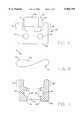
- FIG. 1depicts a side view of a connector
- FIG. 2depicts a perspective view of a cable
- FIG. 3depicts a cross sectional view of the connector as viewed from the side
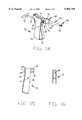
- FIG. 4depicts a cross sectional view of a pin as viewed facing a groove from the front face
- FIG. 5depicts a side view of the pin
- FIG. 6depicts a cross sectional view of the pin as viewed from the front
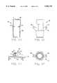
- FIG. 7depicts a top view of the connector with the cable forming a loop by entering a first face opposite to a second face from which it exits;
- FIG. 8depicts a top view of a connector with the cable forming a loop by entering the same face from which it exits;
- FIG. 9depicts a cross sectional view of the connector in a secured position, with a portion of the cable residing in an opening of the pin, as viewed from the side of the connector;
- FIG. 10depicts a cross sectional view of the connector, with the cable being movable within the connector body, as viewed from the side;
- FIG. 11depicts a cross sectional view of the connector, with the cable being secured in an immobile position within the connector, as viewed from the side;
- FIG. 12depicts a cross sectional view of the connector, with the cable being movable within the connector body, as viewed from the bottom;
- FIG. 13depicts a cross sectional view of the connector, with the cable secured in an immobile position within the connector body, as viewed from the bottom;
- FIG. 14depicts a perspective view of a tensioner
- FIG. 15depicts a cross sectional view of a body of the tensioner, as viewed from the side;
- FIG. 16depicts a rear view of the body of the tensioner
- FIG. 17depicts a cross sectional view of the tensioner, as viewed from the side;
- FIG. 18depicts a tip of a shaft of the tensioner, as viewed from the front;
- FIG. 19depicts the tip of the shaft as viewed from the side
- FIG. 20depicts a cross-sectional view of a bushing cover of the tensioner as viewed from the side of the bushing cover;
- FIG. 21depicts a side view of the bushing cover
- FIG. 22depicts a top view of the bushing cover
- FIG. 23depicts a cross sectional partial view of the bushing cover with a cable clamp, as viewed from the side.
- FIG. 1depicts an embodiment of a connector 20 constructed according to the teachings of the present invention.
- the connector 20includes a connector body 24 and a pin 22.
- a cable 10may be passed through the ducts 26 to form a loop for engaging a portion of a human bone.
- the cable 10may be looped around a variety of human bone portions involved in various surgical procedures.
- the surgical procedures which may make use of a surgical cable systeminclude, but are not limited to: spine surgery; total hip arthroplasty; fracture fixation; closure of the sternum following open heart surgery; and oral/facial surgery to repair mandibular fractures.
- the cable 10is preferably used for engaging a portion of the human spine.
- the term "cable" within the context of this applicationis taken to mean an elongated flexible member.
- An embodiment of the cable 10is illustrated in FIG. 2.
- the cable 10includes a leader portion 12, a main portion 14, and a tip 16.
- the main portion 14is preferably comprised of a substantially flexible stranded metal wire.
- the main portion 14may be comprised of any substantially flexible material including, but not limited to, steel, nylon, or various plastics.
- the main portion 14is preferably made of titanium or stainless steel.
- the cable 10preferably has a leader portion 12 attached to an end of the cable.
- the leader portion 12may comprise a non-stranded wire that is substantially less flexible than the main portion 14.
- the leader portion 12may be comprised of any substantially flexible material including, but not limited to, steel, nylon, or various plastics.
- the leader portion 12is preferably made of titanium or stainless steel.
- the leader portion 12is preferably made of the same material as the main portion 14 of the cable 10. The leader portion 12 may be used to guide the cable 10 around the bone and through the various openings of the connector 20.
- the cable 10may include a tip 16 attached to an end of the cable.
- the tip 16is preferably of a diameter that is substantially larger than the diameter of the main portion 14.
- the tip 16may be made of the same material as the main portion.
- the tip 16is preferably made of titanium or stainless steel.
- the tip 16may be larger than the diameter of the ducts 26, (shown in FIG. 1), such that the tip 16 is inhibited from passing through the ducts. Thus, tip 16 may function to prevent the cable 10 from passing entirely through the ducts 26.
- the cable 10is preferably made by twisting together multiple wire strands around a cable core.
- the wire strandsare preferably made by twisting six filaments around a central filament in a helical orientation.
- the filamentsmay be made by reducing the diameter of a wire to a thickness of less than 0.0005 inches, and more preferably to a diameter of 0.0003 inches.
- the cable coreis preferably made by twisting six wire strands over a central strand in a helical orientation.
- the cable 10is preferably made by twisting twelve strands over the cable core. After the strands are twisted to form the cable 10, the cable may be hammered repeatedly to give a smooth surface.
- the cable 10may be cut into the appropriate length by a cutting apparatus.
- the cable 10is preferably cut by a laser. By applying tension on the cable 10 during the cutting process an end of the cable may be formed into an enlarged tip 16.
- the leader portion 12may be welded onto an end of the cable 10 before use.
- the cablemay be cleaned repeatedly during the manufacturing procedure.
- FIG. 3depicts a cross sectional view of the connector body 24 of the connector 20.
- the connector body 24preferably includes an internal cavity 28 for holding a pin 22 within the connector body 24.
- the internal cavity 28may be substantially cylindrical in shape and preferably passes longitudinally through the entire connector body 24.
- the connector body 24may include a duct 26 that passes transversally through the entire connector body.
- the duct 26is preferably oriented substantially perpendicular to the internal cavity 28.
- the connector body 24preferably includes at least two ducts 26 that pass transversally through the entire connector body.
- the ducts 26preferably communicate with the internal cavity 28 via an aperture 30.
- the ducts 26are preferably positioned such that a cable 10 lying within the duct may extend into the internal cavity 28.
- the pin 22preferably includes an upper portion 36 and a lower portion 40, as depicted in FIG. 4.
- the pin 22may also include a transition portion 38 oriented between the upper potion 36 and the lower portion 40.
- the upper portion 36is preferably of a diameter substantially larger than the diameter of the lower portion 40.
- the upper portion 36is preferably of a diameter such that it is incapable of passing into the internal cavity 28.
- the lower portion 40 of the pin 22is preferably of a diameter such that the lower portion may fit into the internal cavity 28 (shown in FIG. 2).
- the diameter of the transition portion 38may be variable, becoming narrower in a direction from the upper portion 36 toward the lower portion 40.
- the bottom of the pin 43may be deflected outward to substantially secure the pin 22 within the internal cavity 28.
- the pin 22preferably includes two grooves 42, as depicted in FIG. 5.
- the grooves 42may be substantially rectangular in shape, comprising a width that is substantially larger than the diameter of the cable 10.
- the grooves 42are preferably oriented on opposing sides of the lower portion 40 of the pin 22. Referring to FIG. 9, the pin 22 may lie within the internal cavity 28 such that the grooves 42 lie in the plane defined by the ducts 26.
- the grooves 42may be substantially aligned with the ducts 26, with an aperture 30 positioned between each duct and groove.
- the pin 22may be oriented within the internal cavity 28, with the grooves 42 substantially aligned with the ducts 26, such that the cable 10 may pass freely through the connector body 24.
- the pin 22may also be oriented within the internal cavity 28, with the grooves 42 positioned substantially perpendicular to the ducts 26, such that the cable 10 is secured within the connector body 24.
- the pin 22preferably includes an opening 44, as depicted in FIG. 6.
- the opening 44is preferably substantially cylindrical in shape and preferably passes longitudinally through the entire pin 22.
- the pinmay surround a portion of the opening such that the opening is U-shaped or V-shaped.
- the pinpreferably surrounds the entire opening.
- the opening 44preferably includes an upper portion 46 and a lower portion 48.
- the pin 22may also include a transition portion 47 oriented between the upper potion 46 and the lower portion 48.
- the upper portion 46is preferably of a diameter substantially larger than the diameter of the lower portion 48.
- the diameter of the upper portion 46is preferably substantially larger than the diameter of the tip 16 of cable 10.
- the diameter of the lower portion 48is preferably substantially smaller than the diameter of the tip 16 of cable 10. In this manner, the opening 44 may prevent a cable 10, having a tip 16, from passing completely through the opening.
- the upper portion 46 of the opening 44may be chosen to couple with any suitable device adapted to apply a torsional force.
- the upper portion 46may be substantially rectangular for receiving a flat head torsioning device, such as a screw driver.
- the upper portion 46may also be substantially cross shaped for receiving a cross shaped head of a torsioning device, such as a Phillips head screwdriver.
- the upper portion 46is preferably hexagonal in shape for receiving a hexagonal head of a torsioning device, such as an Allen wrench.
- FIG. 7depicts a connector 20 with a cable 10 threaded through the connector body 24 to form a loop according to one embodiment.
- the cable 10is preferably threaded through a duct 26, around a human bone element, and back through a separate duct 26 to form a loop.
- the loopis formed such that the ends of the cable 10 lie in a substantially parallel orientation with respect to each other.
- the cable 10is preferably threaded through a duct 26, around a human bone element, and back through another duct to form a loop, reentering the connector body 24 from the face 35 on the side opposite to the face 33 which the cable initially exited.
- the pin 22may be inserted within the connector body 24, after the cable 10 has been looped around a human bone element and passed through the connector body 24 to secure the cable within the connector body.
- the pin 22may be removed from the connector body 24, subsequent to securing the cable 10 within the connector body, to allow the cable to be moved within the connector body. Removal of the pin 22 may be prevented by deforming the bottom of the pin.
- FIG. 8depicts another embodiment in which the cable 10 is preferably threaded through a duct 26, around a human bone element, and back through a separate duct to form a loop, reentering the connector body 24 from the same face 33 of the connector body that the cable initially exited.
- the pin 22may be inserted within the connector body 24 to secure the cable 10 within the connector body. While the cable 10 is secured the cable is no longer able to move within the connector 20.
- the pin 22may be removed from the connector body 24, subsequent to securing the cable 10 within the connector body, to allow the cable to be moved within the connector body.
- FIG. 9depicts another embodiment in which the cable 10 is preferably threaded through the opening 44, around a human bone element, and back through a duct 26 to form a loop.
- the ends of the cable 10may lie in a substantially perpendicular orientation with respect to each other (not shown).
- the pin 22may be inserted within the connector body 24 to secure the cable 10 within the connector body.
- the pin 22may be removed from the connector body 24, subsequent to securing the cable 10 within the connector body, to allow the cable to be movable within the connector body.
- Tension on the cable 10may pull the tip 16 of the cable against the lower portion 48 of the opening 44. In this manner, the cable 10 may be prevented from moving within the opening 44.
- the pin 22may be positioned within the internal cavity 28 before the cable 10 is threaded through the ducts 26.
- the cable 10may be threaded through the ducts 26 of the connector body 24 while the pin 22 is mounted within the internal cavity 28.
- the pin 22is preferably oriented such that the grooves 42 of the pin are substantially aligned with the ducts 26, as depicted in FIGS. 10 and 12.
- the pin 22may be rotated, subsequent to the cable 10 being passed through the connector body 24, such that the grooves 42 are substantially perpendicular to the ducts 26.
- the ungrooved portion of the pin 22may compress the cable 10 against the connector body 24, securing the cable, as depicted in FIGS. 11 and 13.
- the pin 22may be further rotated such that the grooves 42 are once again aligned with the ducts 26. In this manner, the cable 10 may be repeatedly moved and secured within the connector body 24.
- the cable 10may be threaded through the pin 22 and through a duct 26 of the connector body 24, as depicted in FIG. 9.
- the pin 22may be rotated within the connector body 24 to secure the cable 10 in an immobile position within the connector body. Subsequent to securing the cable 10 in an immobile position within the connector body 24, the pin 22 may be further rotated such that the cable may again be movable within the connector body. Tension on the cable 10 may pull the tip 16 of the cable against the lower portion 48 of the opening 44. In this manner, the cable 10 may be prevented from moving within the opening 44.
- the connector body 24preferably has two substantially flat arms 32 extending out from the top face of the connector body, as depicted in FIG. 9.
- the arms 32are preferably oriented opposite to each other, and the internal cavity 28 is preferably located between the two arms.
- the upper portion 36 of the pin 22may have at least two substantially flat edges 34.
- the upper portion 36 of the pin 22more preferably has four substantially flat edges 34 (shown in FIG. 7).
- the edges 34are preferably oriented on opposing sides of the upper portion 36 of the pin 22.
- the pin 22may be mounted within the internal cavity 28 such that the edges 34 are contained by the arms 32 of the connector body 24.
- the arms 32may interact with the edges 34 such that rotation of the pin 22 is hindered.
- the pin 22may be rotatable when sufficient force is applied to the pin to overcome the hindering force of the arms 32.
- the pin 22may be inserted within the internal cavity 28 and the pin bottom 43 deflected outward.
- the diameter of the bottom 45 of the internal cavity 28is preferably tapered, becoming wider in a direction toward the bottom 45 of the connector body 24.
- the deflection of the bottom 43 of pin 22is tapered to match the tapering of the internal cavity 28.
- the pin 22is preferably rotatable within the internal cavity 28.
- the lower portion 40 of the pin 22is preferably of a diameter such that, when positioned within the internal cavity 28, the lower portion may compress the cable 10 against the wall of the duct 26, securing the cable in place.
- the cable 10is preferably formed into a loop and tensioned prior to securing the cable within the connector body 24.
- the corners of the edge 34 of the pin 22may rest upon the inner faces of the arms 32.
- the force exerted by the arms 32 upon the corners of the edges 34may prevent the pin 22 from rotating due to the tension of the cable 10.
- the pin 22, however,may be rotated by an operator to a position which allows the cable 10 to be movable through the connector body 24.
- the force required by the operator to move the pin 22 into an unsecured positionis preferably greater than the rotational force exerted on the pin by the cable 10 when in a secured position.
- the surgical cable systempreferably includes a tensioner 50 adapted to vary the tension of the cable 10 and secure the cable within the connector 20.
- a preferred embodiment of the tensioner 50is depicted in FIG. 14.
- the tensioner 50preferably includes a body 52, a shaft 58 for contacting the connector 20, a driver 56 for positioning the pin 22 within the connector 20, and an arm 54 for adjusting the position of the shaft 58.
- the parts of the tensioner 50may be made of a variety of substantially inflexible materials including, but not limited to, instrument grade stainless steel, aluminum, and various plastics.
- FIG. 15depicts a cross sectional side view of the body 52.
- the body 52is preferably substantially rectangular and hollow.
- the body 52preferably includes a substantially circular front opening 82 and a substantially oval rear opening 84.
- the body 52may also include a bushing holder 86 extending from the front edge 81 of the body.
- the front opening 82may pass through the bushing holder 86.
- the front opening 82 and the rear opening 84may be aligned such that a rigid, elongated member may be passed through both openings.
- the front edge 81 of the body 52may be uncovered allowing insertion of the arm 54 within the body.
- FIG. 16depicts a preferred embodiment of the rear opening 84 of the body 52.
- the rear opening 84preferably comprises two curved sections and two flat sections.
- the curved sectionsmay be oriented at the top and the bottom of the rear opening 84.
- the flat sectionsmay connect the top curved section to the bottom curved section to form a substantially oval opening.
- the arm 54may be substantially hollow and is preferably mounted within the hollow portion of the body 52, as depicted in FIG. 17.
- the arm 54may be held in place by the arm pin 72.
- the arm pin 72may be substantially cylindrical and hollow.
- the arm pin 72may extend through the entire arm 54 and partially into the sides of the body 52.
- the arm pin 72may be mounted within the body 52 such that the arm 54 is pivotable about the arm pin in a range of about 45 degrees.
- the arm 54may be stopped in a forward position when the top 53 of the arm comes into contact with the body 52, as depicted in FIG. 17.
- the arm 54may be similarly stopped in a rear position when the bottom 55 of the arm 54 comes into contact with the body 52.
- the sides of the arm 54preferably extend above the top of the arm to form a substantially U-shaped pocket.
- the U-shaped pocketmay be adapted to hold a push tab pin 88 that may be mounted over the top of the arm 54 extending into the sides of the arm.
- the push tab 64may be substantially rectangular.
- the push tab 64preferably includes a substantially circular aperture.
- the push tab 64may rest on the front portion of the push tab pin 88.
- the aperture of the push tab 64is preferably sized such that the shaft 58 may be passed through the aperture.
- the push tab 64is preferably placed within the hollow portion of the body 52.
- the shaft 58is preferably fitted through the aperture of the push tab 64, and the lower portion of the push tab is preferably seated against the push tab pin 88.
- the arm spring 92may also lie on the shaft 58, preferably positioned between the push tab 64 and the front 81 of the body 52.
- the arm 54is preferably pivotable about the arm pin 72 such that a bottom portion 55 of the arm may be moved toward the rear 83 of the body 52.
- Rearward motion of the arm 54preferably causes the push tab pin 88 to move toward the front 81 of the body 52.
- Push tab 64preferably rests against the push tab pin 88.
- movement of the push tab 64 toward the front 81preferably makes the push tab pin 88 move in a similar direction.
- the push tab 64may engage the shaft 58, propelling the shaft through the front opening 82 of the body 52.
- the push tab 64Concurrent with the movement of the arm 54, the push tab 64 may also compress the arm spring 92.
- the arm spring 92preferably expands such that the push tab 64, the push tab pin 88, and the arm 54 are returned to their original positions.
- the body 52may further include a lock tab 62 and lock spring 94.
- the lock tab 62may be substantially rectangular.
- the lock tab 62preferably includes a substantially circular aperture.
- the lock tab 62may extend downward from the top of the body 52, as depicted in FIG. 17.
- the apertureis preferably sized such that the shaft 58 may be passed through the aperture.
- the lock spring 94may also lie on the shaft 58, preferably positioned between the lock tab 62 and the body 52.
- the lock spring 94preferably exerts a force on the lock tab 62, forcing it away from the rear 83 of the body 52. Movement of the lock tab 62 in this direction is preferably restricted when the lower portion of the aperture comes into contact with the shaft 58.
- the force exerted by the lock tab 62 upon the shaft 58may restrict the rearward motion of the shaft through the body 52.
- the lock tab 62may be moved toward the front 81 of the body 52 such that the aperture no longer comes into contact with the shaft 58. When oriented in this forward position the lock tab 62 may no longer restrict the rearward motion of the shaft 58.
- the lock tab 62is preferably moved into the forward position to allow the shaft 58 to be moved in a rearward direction within the body 52. Movement of the lock tab 62 toward the front of the body 52 may also compress the lock spring 94. When the pressure being applied to the lock tab 62 is released, the lock spring 94 preferably pushes the lock tab 62 back into its starting position.
- the shaft 58may be a variety of shapes including, but not limited to cylindrical, oval or trapezoidal.
- the shaft 58is preferably substantially cylindrical and hollow.
- the shaft 58may include two flat edges 59 (shown in FIG. 14) that run longitudinally along the entire length of the shaft 58.
- the edges 59are preferably oriented on opposing sides of the shaft 58, giving the shaft a substantially oval shape.
- the rear opening 84 of the body 52is preferably shaped to allow a shaft 58 of complimentary shape to pass through the rear opening.
- the rear opening 84is preferably shaped to inhibit rotation of the shaft 58 within the body 52.
- the width of the hollow portion of the shaft 58is slightly greater than the diameter of the driver 56, thereby allowing the driver to freely pass through the shaft.
- the shaft 58may also include a knob 96 at an end of the shaft, as depicted in FIG. 17.
- the knob 96may be a threaded nut which is screwed onto the shaft 58.
- the knob 96may be used to position the shaft 58 within the body 52.
- the shaft 58preferably includes a tip 80 proximate an end of the shaft which is adapted to hold the connector 20.
- the tip 80is preferably located at the end of the shaft 58 which extends from the front 81 of the body 52.
- FIG. 18depicts a preferred embodiment of the tip 80.
- the tip 80may be slightly larger than the diameter of the shaft 58.
- the tip 80preferably includes two indentations 78 running along the outside surface of the tip.
- the indentations 78are preferably oriented on opposing sides of the tip 80.
- the indentations 78are preferably sized such that the width of the indentations are substantially greater than the width of the cable 10.
- the depth of the indentations 78is preferably tapered, becoming shallower in a direction from the end of the shaft 58 toward the body 52.
- the tip 80may include a recessed opening which is adapted to couple with the connector 20.
- the front of the tip 80is depicted in FIG. 19.
- the front of the tip 80preferably contains a first slot 96 and a second slot 98.
- the first slot 96preferably runs across the end of the tip 80, in the plane of the tip 80 formed by the two indentations 78.
- the second slot 98preferably runs in a substantially perpendicular orientation to the first slot 96.
- the depth of the second slot 98may be substantially greater than the depth of the first slot 96.
- the connector 20may be mounted within the tip 80 such that the ducts 26 are oriented toward the indentations 78 of the tip. This arrangement preferably allows the cable 10 to freely pass through the connector 20 and along the indentations 78 while the connector 20 is mounted within the tip 80.
- the body 52may also include a substantially cylindrical and hollow bushing cover 66, as depicted in FIGS. 20, 21, and 22.
- the bushing cover 66preferably includes an upper chamber 100, a lower chamber 102, a divider 104 and two arms 106.
- the upper chamber 100is preferably sized such that the bushing cover 66 may be inserted over the bushing holder 86, as depicted in FIG. 17.
- the distance between the divider 104 and the top 101 of the bushing cover 66may be substantially less than the distance that bushing holder 86 extends out from the body 52. The distance is set such that a space may exist between the bushing cover 66 and the front edge 81of the body 52.
- the divider 104preferably extends partially into the interior of the bushing cover 66, at a distance allowing the shaft 58 to pass through the bushing cover.
- the lower chamber 102is preferably sized to allow the bushing 60 and the bushing spring 90 to be inserted together within the chamber, as depicted in FIG. 17.
- the arms 106preferably extend from opposing sides of the bushing cover 66. The end of each arm 106 is preferably shaped into a substantially U-shaped groove, as depicted in FIG. 22.
- the bushing spring 90is preferably sized to fit within the lower chamber 102.
- the bushing spring 90is preferably sized to fit over the bushing 60.
- the body 52may include a substantially cylindrical and hollow bushing 60. It is preferred that the width of the hollow portion of the bushing 60 and the diameter of the shaft 58 be substantially equal.
- the shape of the hollow portionis preferably complimentary to the shape of the shaft 58.
- the hollow sectionmay extend through the longitudinal axis of the bushing 60.
- the bushing 60is preferably mounted within the bushing holder 86. The engagement of the bushing 60 with the shaft 58, while the bushing 60 is mounted within the bushing holder 86, preferably minimizes the lateral movement of the shaft within the body 52.
- the bushing holder 86preferably contains female threading.
- the bushing 60may include a threaded end, sized to fit the female threading of the bushing holder 86. The threaded end of the bushing 60 preferably engages the bushing holder 86 such that rotation of the bushing in a tightening direction moves the threaded end into the bushing holder.
- the bushing 60is preferably adapted to hold the bushing cover 66 onto the bushing holder 86, whereby the bushing cover is freely rotatable about the bushing holder.
- the bushing 60preferably includes a flanged end.
- the bushing cover 66 and the bushing spring 90are preferably placed on the bushing holder 86, such that the bushing spring lies within the lower chamber 102 of the bushing cover.
- the bushing spring 90may rest against a front edge of the bushing holder 86.
- the bushing 60may be fastened by screwing the threaded end into the threaded portion of the bushing holder 86.
- the flanged end of the bushing 60preferably presses against the bushing cover 66 to hold the bushing cover against the bushing holder 86.
- the flanged end of the bushing 60may also compress the bushing spring 90.
- the bushing spring 90is adapted to prevent the bushing 60 from being overtightened. Overtightening of the bushing 60 might hinder or prevent rotation of the bushing cover 66 about the bushing holder 86.
- FIG. 23depicts a portion of the bushing cover 66 which preferably includes a cable clamp 68 adapted to secure a cable 10 against a portion of the bushing cover.
- the bushing cover 66preferably includes at least two cable clamps 68.
- the cable clamp 68preferably includes a lever 76, a pin 70, and a spring 108.
- the lever 76may include a substantially hollowed out portion 109 and a clamping portion 110.
- the lever 76is preferably connected to an arm 106 of the bushing cover 66 with a substantially cylindrical pin 70.
- the pin 70may extend through both the lever 76 and the U-shaped groove of the arm 106.
- the pin 70may be mounted within the U-shaped groove of the arm 106 such that the lever 76 is pivotable about the pin.
- the spring 108preferably lies on the pin 70 and extends into the bushing cover 66 and along the lever 76.
- the spring 108preferably extends into the hollow portion of the lever 76.
- spring 108In its resting position spring 108 preferably exerts a force against the inside edge of the hollow portion 109 such that the lever 76 is moved away from the bushing cover 66.
- the clamping portion 110is preferably disposed against the bushing cover.
- the lever 76may pivot around the pin 70 such that the clamping portion 110 is no longer in contact with the bushing cover 66.
- the cable 10may be passed under the lever 76 while the clamping portion 110 is in its raised position.
- the depression of the clamp lever 76preferably compresses the spring 108. Removal of the force being applied to the lever 76 preferably allows the spring 108 to expand, thereby forcing the clamping portion 110 to return to the bushing cover 66. If a cable 10 is present when the force is released from the lever 76, the clamping portion 110 may become pressed against the cable, securing it in place against the bushing cover 66.
- the arm spring 92 and the lock spring 94may be compression springs.
- the spring 108 of the cable lock 68is preferably a torsion spring.
- the bushing spring 90is preferably a spring washer.
- the term "spring washer” in the context of this applicationis meant to mean a spring adapted to apply a predetermined force on adjacent members in an assembly.
- the driver 56may include a handle 114 attached to the elongated member 112 of the driver.
- the handle 114is preferably a rod that is attached to the elongated member 112 in a perpendicular orientation, such that the driver 56 is substantially T-shaped.
- the handle 114may be rotated to allow the driver 56 to be moved in tortionally.
- the elongated member 112may be substantially longer than the shaft 58.
- the driver 56preferably includes a head 116 adapted to engage the pin 22 of the connector 20.
- the head 116is preferably located at an end of the elongated member 112 opposite to the handle 114.
- the shape of head 116may be chosen to couple with a pin 22 of suitably recessed shape such that rotation of the handle may apply a tortional force to the pin.
- the head 116is preferably hexagonal in shape for coupling with the hexagonal recess of the upper portion 46 of the opening 44 of the pin 22.
- the shaft 58may be substantially cylindrical and hollow.
- the hollow portion of the shaft 58is preferably sized such that the elongated portion 112 of the driver 56 may be passed through the center of the shaft.
- the shaft 58is configured such that the driver 56 may engage the pin 22 while the connector 20 is in contact with the shaft.
- the driver 56may engage the pin 22 such that rotation of the driver 56 causes the pin to rotate.
- the driver 56preferably engages the pin 22 such that rotation of the driver causes the pin 22 to rotate into a position which secures the cable 10 within the connector 20. Once the cable 10 has been clamped into this position, the driver 56 may engage the pin 22 such that rotation of the driver causes the pin to rotate into a position which allows movement of the cable within the connector 20.
- the surgical procedure for implanting a surgical cable system around a portion of a human boneincludes forming a loop around the desired portion, tensioning the cable 10, and securing the cable within the connector 20.
- the loopis preferably formed by threading the cable 10 through the connector 20, around a portion of the human bone and back through the connector.
- the cable 10may be looped around two or more adjacent vertebra.
- the cable 10may be passed around a vertebra and a spinal fixation device.
- the spinal fixation deviceis adapted to immobilize a section of the human spine and may be a rod.
- the cable 10may be passed through a duct 26 of the connector 20, around a portion of the human bone, and back through a different duct 26.
- the cable 10may be threaded through the connector 20 exiting from the rear face 33 of the connector body 24. After encircling a bone member the cable 10 may reenter the connector body 24 from the front face 35.
- the cable 10may be threaded through the connector 20 exiting from the rear face 33 of the connector body 24. After encircling a bone member the cable 10 may reenter the connector body 24 from the rear face 33, forming a loop around the bone member.
- the ends of the cable 10may extend out from the connector body 24. The ends may be in a substantially parallel orientation with respect to each other.
- the cable 10may include tip 16, as depicted in FIG. 1.
- the tip 16is preferably of a diameter that is substantially larger than the diameter of a duct 26.
- the tip 16preferably inhibits the cable 10 from passing completely through the duct 26.
- the cable 10may be threaded through the connector 20, exiting from the rear face 33 of the connector body 24.
- the cable 10is preferably threaded through the connector body 24 until the tip 16 is disposed against the front face 34 of the connector body 24.
- the cable 10may reenter the connector body 24 from the front face 35.
- the cable 10may reenter the connector body 24 from the rear face 33 of the connector body.
- the tip 16may be disposed against the front face 35 of the connector body 24.
- the tip 16may remain disposed against the face of the connector body 24 until the tension of the cable 10 is released.
- the tip 16is preferably of a diameter that is substantially larger than the diameter of an opening 44 of pin 22.
- the tip 16preferably inhibits the cable 10 from passing completely through the opening 44.
- the cable 10is preferably threaded through the opening 44 until the tip 16 is disposed against the lower portion 48 of the opening.
- the cable 10may be passed into the connector body 24 through one of the ducts 26.
- the pin 22is preferably oriented to allow this passage of the cable 10 through one of the ducts 26.
- the tip 16may be disposed against lower portion 48 of the opening 44.
- the tip 16may remain disposed against the lower portion 48 of the opening 44 until the tension of the cable 10 is released.
- a tensioner 50may be used to increase the tension on a cable 10 after it has been encircled around a human bone member.
- the preferred embodiment of the tensioner 50is illustrated in FIG. 14.
- the tensioner 50may be prepared to receive the connector 20 by positioning the shaft 58 such that the tip 80 is positioned proximate to the front of the 10 bushing 60.
- the shaft 58may be positionable within the body 52 while the lock tab 62 is in a forward position.
- the lock tab 62may be moved into the forward position by applying pressure to the rear face of the lock tab 62. Pressure on the lock tab 62 may be released allowing the lock tab to move away from the tensioner body 52. In this released position the lock tab 62 may prevent the rearward movement of the shaft 58.
- the connectormay be engaged by the tip 80 of the tensioner 50.
- the connector 20is engaged by the tip 80 such that the front and rear faces of the connector are aligned with the indentations 78 (see FIG. 19).
- the top of the connector 20may be substantially positioned within the tip 80.
- the pin 22may be mounted within the connector body 24, and the connector body may be engaged by the tip 80.
- a cable endis preferably positioned along the indentations 78 of the tip 80.
- the cable endis preferably clamped to the tensioner 50 by the cable clamp 68.
- the clamping portion 110 of the cable clamp 68may be disposed against the side of the bushing cover 66 while in the resting position. When pressed with sufficient force the lever 76 may pivot around the arm pin 72 such that the clamping portion 110 is no longer in contact with the bushing cover 66.
- the cable 10may be passed under the lever 76 while the clamping portion 110 is raised. Removal of the force being applied to the lever 76 preferably causes the clamping portion 110 to move toward the bushing cover 66.
- the clamping portion 110may become pressed against the cable, thereby securing it in place against the bushing cover 66.
- one end of the cable 10is preferably secured to the bushing cover 66, using the cable clamps 68.
- both ends of the cable 10are preferably secured to the bushing cover 66.
- Pressuremay then be applied to the arm 54 of the tensioner 50 to pivot the arm around the arm pin 72 such that the arm moves in a direction toward the body 52 of the tensioner 50. Movement of the arm 54 toward the body 52 may be accompanied by movement of the shaft 58 away from the body 52. The angle to which the arm 54 is pivoted may determine the distance the shaft 58 extends from the body 52.
- the armWhen the pressure on the arm 54 is released, the arm preferably moves away from the body 52. Movement of the arm 54 away from the body 52 preferably does not effect the position of the shaft 58.
- movement of the shaft 58 away from the body 52preferably pulls the cable 10 through the connector 20 in a direction away from the connector. As a result, the tension on the cable 10 preferably increases.
- the arm 54may be repeatedly pressured and released as many times as necessary to achieve the desired tension.
- a pin 22may be inserted into the connector body 24, after the cable 10 has been tensioned, to secure the cable within the connector 20.
- the driver 56may be used to insert the pin 22 into the connector body 24.
- the pin 22may be placed in the connector body 24 prior to tensioning the cable 10.
- the pin 22may be positioned within the tip 80.
- the driver 56may be inserted through the center of the shaft 58 until it engages the pin 22.
- the end of the driver 56is preferably shaped to fit within the opening 44 of the pin 22.
- the rotation of the driver 56may be accompanied by rotation of the pin 22 while the driver is inserted within the opening 44.
- the pin 22is preferably oriented such that the cable 10 may pass through one of the ducts 26.
- Rotation of the pin 22may alter the orientation of the pin such that the pin secures a portion of the cable 10 within the connector body 24.
- the pin 22is preferably rotated 90° into a securing orientation. Rotation of the pin 22 is preferably performed after the cable 10 has been tensioned. In this manner, the diver 56 may rotate the pin 22 to secure a portion of the cable 10 within the connector 20 without removing the connector from the tip 80.
- the tensioner 50may be disengaged from the connector.
- the cable 10may be removed from the cable clamp 68 before disengaging the tensioner 50.
- pressuremay be applied to the lever 76, causing the lever to lift from the bushing cover 66.
- the securing force exerted by the clamping portion 110is removed, allowing the cable 10 to be removed from under the clamping portion.
- the connector 20may then be removed from the tip 80 of the tensioner 50.
- the cable 10may need to be retensioned after the connector 20 has been removed from the tensioner 50.
- the connector 20may be reinserted into the tip 80 of the tensioner 50.
- the cable 10may be secured against the tensioner 50 with the cable clamp 68 of the tensioner 50.
- the driver 56may be inserted into the opening 44 of the pin 22. Under these circumstances the pin 22 may be rotated by the driver 56 to an orientation which allows movement of the cable 10 through the connector body 24.
- the cable 10may be retensioned by operation of the tensioner arm 54. When the desired tension is achieved, the cable 10 may be secured by the rotation of the pin 22 within the connector 20.
Landscapes
- Health & Medical Sciences (AREA)
- Orthopedic Medicine & Surgery (AREA)
- Life Sciences & Earth Sciences (AREA)
- Surgery (AREA)
- Medical Informatics (AREA)
- Engineering & Computer Science (AREA)
- Biomedical Technology (AREA)
- Heart & Thoracic Surgery (AREA)
- Nuclear Medicine, Radiotherapy & Molecular Imaging (AREA)
- Molecular Biology (AREA)
- Animal Behavior & Ethology (AREA)
- General Health & Medical Sciences (AREA)
- Public Health (AREA)
- Veterinary Medicine (AREA)
- Neurology (AREA)
- Surgical Instruments (AREA)
Abstract
Description
Claims (200)
Priority Applications (15)
| Application Number | Priority Date | Filing Date | Title |
|---|---|---|---|
| US08/919,127US5964769A (en) | 1997-08-26 | 1997-08-26 | Surgical cable system and method |
| US09/085,186US6053921A (en) | 1997-08-26 | 1998-05-26 | Surgical cable system and method |
| CA002297837ACA2297837A1 (en) | 1997-08-26 | 1998-07-07 | Surgical cable system and method |
| EP98934298AEP1009311B1 (en) | 1997-08-26 | 1998-07-07 | Surgical cable system |
| DE69818277TDE69818277T2 (en) | 1997-08-26 | 1998-07-07 | SURGICAL CABLE SYSTEM |
| AU83856/98AAU732474B2 (en) | 1997-08-26 | 1998-07-07 | Surgical cable system and method |
| JP2000507300AJP2001513391A (en) | 1997-08-26 | 1998-07-07 | Surgical cable system and method |
| PCT/US1998/014058WO1999009904A1 (en) | 1997-08-26 | 1998-07-07 | Surgical cable system and method |
| AT98934298TATE249788T1 (en) | 1997-08-26 | 1998-07-07 | SURGICAL CABLE SYSTEM |
| US09/211,888US6391030B1 (en) | 1997-08-26 | 1998-12-15 | Surgical cable system and method |
| US09/211,887US5935133A (en) | 1997-08-26 | 1998-12-15 | Surgical cable system and method |
| US09/360,062US6682533B1 (en) | 1997-08-26 | 1999-07-23 | Surgical cable system and method |
| JP2005280660AJP2006068540A (en) | 1997-08-26 | 2005-09-27 | Surgical cable system |
| JP2005280656AJP2006068539A (en) | 1997-08-26 | 2005-09-27 | Tensioner |
| JP2005280654AJP2006051377A (en) | 1997-08-26 | 2005-09-27 | Connector |
Applications Claiming Priority (1)
| Application Number | Priority Date | Filing Date | Title |
|---|---|---|---|
| US08/919,127US5964769A (en) | 1997-08-26 | 1997-08-26 | Surgical cable system and method |
Related Child Applications (3)
| Application Number | Title | Priority Date | Filing Date |
|---|---|---|---|
| US09/085,186Continuation-In-PartUS6053921A (en) | 1997-08-26 | 1998-05-26 | Surgical cable system and method |
| US09/211,888DivisionUS6391030B1 (en) | 1997-08-26 | 1998-12-15 | Surgical cable system and method |
| US09/211,887DivisionUS5935133A (en) | 1997-08-26 | 1998-12-15 | Surgical cable system and method |
Publications (1)
| Publication Number | Publication Date |
|---|---|
| US5964769Atrue US5964769A (en) | 1999-10-12 |
Family
ID=25441544
Family Applications (4)
| Application Number | Title | Priority Date | Filing Date |
|---|---|---|---|
| US08/919,127Expired - LifetimeUS5964769A (en) | 1997-08-26 | 1997-08-26 | Surgical cable system and method |
| US09/211,888Expired - LifetimeUS6391030B1 (en) | 1997-08-26 | 1998-12-15 | Surgical cable system and method |
| US09/211,887Expired - LifetimeUS5935133A (en) | 1997-08-26 | 1998-12-15 | Surgical cable system and method |
| US09/360,062Expired - Fee RelatedUS6682533B1 (en) | 1997-08-26 | 1999-07-23 | Surgical cable system and method |
Family Applications After (3)
| Application Number | Title | Priority Date | Filing Date |
|---|---|---|---|
| US09/211,888Expired - LifetimeUS6391030B1 (en) | 1997-08-26 | 1998-12-15 | Surgical cable system and method |
| US09/211,887Expired - LifetimeUS5935133A (en) | 1997-08-26 | 1998-12-15 | Surgical cable system and method |
| US09/360,062Expired - Fee RelatedUS6682533B1 (en) | 1997-08-26 | 1999-07-23 | Surgical cable system and method |
Country Status (1)
| Country | Link |
|---|---|
| US (4) | US5964769A (en) |
Cited By (199)
| Publication number | Priority date | Publication date | Assignee | Title |
|---|---|---|---|---|
| US6248106B1 (en) | 2000-02-25 | 2001-06-19 | Bret Ferree | Cross-coupled vertebral stabilizers |
| US6261291B1 (en) | 1999-07-08 | 2001-07-17 | David J. Talaber | Orthopedic implant assembly |
| US6391030B1 (en)* | 1997-08-26 | 2002-05-21 | Spinal Concepts, Inc. | Surgical cable system and method |
| US6423065B2 (en) | 2000-02-25 | 2002-07-23 | Bret A. Ferree | Cross-coupled vertebral stabilizers including cam-operated cable connectors |
| US20020133155A1 (en)* | 2000-02-25 | 2002-09-19 | Ferree Bret A. | Cross-coupled vertebral stabilizers incorporating spinal motion restriction |
| US6514255B1 (en) | 2000-02-25 | 2003-02-04 | Bret Ferree | Sublaminar spinal fixation apparatus |
| US20030171752A1 (en)* | 1998-04-29 | 2003-09-11 | Richard Assaker | Spinal osteosynthesis system for anterior fixation |
| US6689140B2 (en) | 2000-10-02 | 2004-02-10 | Howmedica Osteonics Corp. | System and method for spinal reconstruction |
| US20040087954A1 (en)* | 2002-08-28 | 2004-05-06 | Allen C . Wayne | Systems, methods, and apparatuses for clamping and reclamping an orthopedic surgical cable |
| US20040111091A1 (en)* | 2002-05-21 | 2004-06-10 | James Ogilvie | Reduction cable and bone anchor |
| US20040138666A1 (en)* | 2003-01-10 | 2004-07-15 | Molz Fred J. | Flexible member tensioning instruments and methods |
| US20040236327A1 (en)* | 2003-05-23 | 2004-11-25 | Paul David C. | Spine stabilization system |
| US20050070904A1 (en)* | 2003-09-29 | 2005-03-31 | Darin Gerlach | Bone plates and bone plate assemblies |
| US20050096699A1 (en)* | 2003-11-05 | 2005-05-05 | Applied Medical Resources Corporation | Suture securing device and method |
| US20050119667A1 (en)* | 2003-12-02 | 2005-06-02 | Eurosurgical Sa | Clip-type surgical instrument for spinal implant |
| US20050192569A1 (en)* | 1999-03-30 | 2005-09-01 | Howmedica Osteonics Corp. | Apparatus for spinal stabilization |
| US20050209698A1 (en)* | 2003-08-05 | 2005-09-22 | Gordon Charles R | Expandable intervertebral implant |
| US20050216017A1 (en)* | 2004-03-09 | 2005-09-29 | Louie Fielding | Spinal implant and method for restricting spinal flexion |
| US20050240191A1 (en)* | 2004-04-21 | 2005-10-27 | Thomas Albertson | Sternal reconstruction system |
| US20050240198A1 (en)* | 2004-04-21 | 2005-10-27 | Thomas Albertson | Sternal reconstruction system |
| US6960213B2 (en) | 2001-05-23 | 2005-11-01 | Medicinelodge, Inc. | Apparatus and method for orthopedic fixation |
| US20050277920A1 (en)* | 2004-05-28 | 2005-12-15 | Slivka Michael A | Non-fusion spinal correction systems and methods |
| US20060069390A1 (en)* | 2003-04-15 | 2006-03-30 | Robert Frigg | Bone fixation device |
| US20060149265A1 (en)* | 2004-09-07 | 2006-07-06 | Anthony James | Minimal thickness bone plate locking mechanism |
| US20060167464A1 (en)* | 2004-09-23 | 2006-07-27 | Allen C W | Systems, methods, and apparatuses for tensioning an orthopedic surgical cable |
| US20060229729A1 (en)* | 2003-08-05 | 2006-10-12 | Gordon Charles R | Expandable intervertebral implant for use with instrument |
| US7122036B2 (en)* | 1999-07-01 | 2006-10-17 | Spinevision, S.A. | Connector for an osteosynthesis system intended to provide a connection between two rods of a spinal osteosynthesis system, osteosynthesis system using such a connector, and method of implanting such an osteosynthesis system |
| FR2890851A1 (en)* | 2005-09-21 | 2007-03-23 | Abbott Spine Sa | ANCILLARY TO TENSION A FLEXIBLE LINK. |
| US20070162022A1 (en)* | 2005-12-23 | 2007-07-12 | Howmedica Osteonics Corp. | Porous tendon anchor |
| US20070167950A1 (en)* | 2005-12-22 | 2007-07-19 | Tauro Joseph C | System and method for attaching soft tissue to bone |
| US20080097432A1 (en)* | 2006-09-27 | 2008-04-24 | Depuy Products, Inc. | Flexible bone fixation device |
| WO2008051802A2 (en) | 2006-10-19 | 2008-05-02 | Simpirica Spine, Inc. | Methods and systems for constraint of multiple spine segments |
| WO2008051423A1 (en) | 2006-10-19 | 2008-05-02 | The Board Of Trustees Of The Leland Stanford Junior University | Methods and systems for constraint of spinous processes with attachment |
| US20080140123A1 (en)* | 2006-11-28 | 2008-06-12 | Ferree Bret A | Methods and apparatus for stabilizing a spinal segment |
| US20080140117A1 (en)* | 1997-08-01 | 2008-06-12 | Peter M Bonutti | Method and apparatus for securing a suture |
| US20080195119A1 (en)* | 2007-02-13 | 2008-08-14 | Ferree Bret A | Methods and Devices for Bone, Joint, and Ligament Reconstruction with Bands |
| US20080208223A1 (en)* | 2007-02-26 | 2008-08-28 | Paul Edward Kraemer | Cable clamping device and method of its use |
| US20080243194A1 (en)* | 2005-09-26 | 2008-10-02 | The Regents Of The University Of California | Articulating instrumentation for dynamic spinal stabilization |
| US20090105715A1 (en)* | 2007-10-23 | 2009-04-23 | Karl Pierre Belliard | Bone fixation tensioning tool and method |
| US20090105717A1 (en)* | 2007-10-17 | 2009-04-23 | Stryker Trauma Gmbh | Cam-locking of cable for fracture plate |
| US20090171357A1 (en)* | 2007-12-20 | 2009-07-02 | Medicineloge, Inc. | Collet fixation system |
| US7585311B2 (en) | 2004-06-02 | 2009-09-08 | Kfx Medical Corporation | System and method for attaching soft tissue to bone |
| US20090270920A1 (en)* | 2008-04-24 | 2009-10-29 | Zimmer Spine S.A.S. | System for Stabilizing at Least a Portion of the Spine |
| US20090292317A1 (en)* | 2008-05-20 | 2009-11-26 | Zimmer Spine S.A.S. | System for stabilizing at least two vertebrae |
| WO2009149414A1 (en) | 2008-06-06 | 2009-12-10 | Simpirica Spine, Inc. | Methods and apparatus for locking a band |
| WO2009149407A1 (en) | 2008-06-06 | 2009-12-10 | Simpirica Spine, Inc. | Methods and apparatus for locking a band |
| US20090326585A1 (en)* | 2005-09-20 | 2009-12-31 | Abbott Spine | Vertebral fixing system |
| US20100057655A1 (en)* | 2008-08-25 | 2010-03-04 | Jacobson Jerry I | Systems And Methods For Providing A Magnetic Resonance Treatment To A Subject |
| US20100121387A1 (en)* | 2008-11-07 | 2010-05-13 | Zimmer Spine | Surgical tool for tensioning a flexible member |
| WO2010088621A1 (en) | 2009-02-02 | 2010-08-05 | Simpirica Spine, Inc. | Sacral tether anchor and methods of use |
| US20100211102A1 (en)* | 2007-09-25 | 2010-08-19 | Karl Pierre Belliard | Device for clamping two portions of a braid and an intervertebral implant comprising a spacer, a braid, and such a clamping device |
| US7785351B2 (en) | 2003-08-05 | 2010-08-31 | Flexuspine, Inc. | Artificial functional spinal implant unit system and method for use |
| US20100249839A1 (en)* | 2009-03-30 | 2010-09-30 | Simpirica Spine, Inc. | Methods and apparatus for improving shear loading capacity of a spinal segment |
| US20100249845A1 (en)* | 2007-10-23 | 2010-09-30 | Alain Meunier | Fixing devices and stabilization systems using said fixing devices |
| WO2010121256A1 (en) | 2009-04-17 | 2010-10-21 | Simpirica Spine, Inc. | Structures and methods for constraining spinal processes with single connector |
| US20110034956A1 (en)* | 2002-07-23 | 2011-02-10 | Keyvan Mazda | Vertebral fixing system |
| WO2011017363A1 (en) | 2009-08-04 | 2011-02-10 | Simpirica Spine, Inc. | Methods and systems for increasing the bending stiffness and constraining the spreading of a spinal segment |
| US7909869B2 (en) | 2003-08-05 | 2011-03-22 | Flexuspine, Inc. | Artificial spinal unit assemblies |
| US7959677B2 (en) | 2007-01-19 | 2011-06-14 | Flexuspine, Inc. | Artificial functional spinal unit system and method for use |
| US8029541B2 (en) | 2006-10-19 | 2011-10-04 | Simpirica Spine, Inc. | Methods and systems for laterally stabilized constraint of spinous processes |
| US8062334B2 (en) | 2004-06-02 | 2011-11-22 | Kfx Medical Corporation | Suture anchor |
| US8105367B2 (en) | 2003-09-29 | 2012-01-31 | Smith & Nephew, Inc. | Bone plate and bone plate assemblies including polyaxial fasteners |
| US8114158B2 (en) | 2004-08-03 | 2012-02-14 | Kspine, Inc. | Facet device and method |
| US8118869B2 (en) | 2006-03-08 | 2012-02-21 | Flexuspine, Inc. | Dynamic interbody device |
| US8157844B2 (en) | 2007-10-22 | 2012-04-17 | Flexuspine, Inc. | Dampener system for a posterior stabilization system with a variable length elongated member |
| US8162982B2 (en) | 2006-10-19 | 2012-04-24 | Simpirica Spine, Inc. | Methods and systems for constraint of multiple spine segments |
| US8162979B2 (en) | 2007-06-06 | 2012-04-24 | K Spine, Inc. | Medical device and method to correct deformity |
| US8162994B2 (en) | 2007-10-22 | 2012-04-24 | Flexuspine, Inc. | Posterior stabilization system with isolated, dual dampener systems |
| US8182514B2 (en) | 2007-10-22 | 2012-05-22 | Flexuspine, Inc. | Dampener system for a posterior stabilization system with a fixed length elongated member |
| US8187330B2 (en) | 2007-10-22 | 2012-05-29 | Flexuspine, Inc. | Dampener system for a posterior stabilization system with a variable length elongated member |
| US8187305B2 (en) | 2008-06-06 | 2012-05-29 | Simpirica Spine, Inc. | Methods and apparatus for deploying spinous process constraints |
| US8251998B2 (en) | 2006-08-16 | 2012-08-28 | Biomet Sports Medicine, Llc | Chondral defect repair |
| US8267965B2 (en) | 2007-10-22 | 2012-09-18 | Flexuspine, Inc. | Spinal stabilization systems with dynamic interbody devices |
| US8273106B2 (en) | 2006-02-03 | 2012-09-25 | Biomet Sports Medicine, Llc | Soft tissue repair and conduit device |
| US8292921B2 (en) | 2006-02-03 | 2012-10-23 | Biomet Sports Medicine, Llc | Soft tissue repair device and associated methods |
| US8298262B2 (en) | 2006-02-03 | 2012-10-30 | Biomet Sports Medicine, Llc | Method for tissue fixation |
| US8303604B2 (en) | 2004-11-05 | 2012-11-06 | Biomet Sports Medicine, Llc | Soft tissue repair device and method |
| US20120303065A1 (en)* | 2009-10-27 | 2012-11-29 | Zimmer Spine | Bone holding device |
| US8337525B2 (en) | 2006-02-03 | 2012-12-25 | Biomet Sports Medicine, Llc | Soft tissue repair device and associated methods |
| US8343227B2 (en) | 2009-05-28 | 2013-01-01 | Biomet Manufacturing Corp. | Knee prosthesis assembly with ligament link |
| US8357182B2 (en) | 2009-03-26 | 2013-01-22 | Kspine, Inc. | Alignment system with longitudinal support features |
| US8361113B2 (en) | 2006-02-03 | 2013-01-29 | Biomet Sports Medicine, Llc | Method and apparatus for coupling soft tissue to a bone |
| US8382807B2 (en) | 2005-07-25 | 2013-02-26 | Smith & Nephew, Inc. | Systems and methods for using polyaxial plates |
| US8403961B2 (en) | 2007-06-22 | 2013-03-26 | Simpirica Spine, Inc. | Methods and devices for controlled flexion restriction of spinal segments |
| US8409253B2 (en) | 2006-02-03 | 2013-04-02 | Biomet Sports Medicine, Llc | Soft tissue repair assembly and associated method |
| US8496657B2 (en) | 2006-02-07 | 2013-07-30 | P Tech, Llc. | Methods for utilizing vibratory energy to weld, stake and/or remove implants |
| US8500818B2 (en) | 2006-09-29 | 2013-08-06 | Biomet Manufacturing, Llc | Knee prosthesis assembly with ligament link |
| US8506597B2 (en) | 2011-10-25 | 2013-08-13 | Biomet Sports Medicine, Llc | Method and apparatus for interosseous membrane reconstruction |
| US8523912B2 (en) | 2007-10-22 | 2013-09-03 | Flexuspine, Inc. | Posterior stabilization systems with shared, dual dampener systems |
| US8529606B2 (en) | 2009-03-10 | 2013-09-10 | Simpirica Spine, Inc. | Surgical tether apparatus and methods of use |
| US8551140B2 (en) | 2004-11-05 | 2013-10-08 | Biomet Sports Medicine, Llc | Method and apparatus for coupling soft tissue to bone |
| US8562653B2 (en) | 2009-03-10 | 2013-10-22 | Simpirica Spine, Inc. | Surgical tether apparatus and methods of use |
| US8562647B2 (en) | 2006-09-29 | 2013-10-22 | Biomet Sports Medicine, Llc | Method and apparatus for securing soft tissue to bone |
| US8562645B2 (en) | 2006-09-29 | 2013-10-22 | Biomet Sports Medicine, Llc | Method and apparatus for forming a self-locking adjustable loop |
| US8574235B2 (en) | 2006-02-03 | 2013-11-05 | Biomet Sports Medicine, Llc | Method for trochanteric reattachment |
| US8597327B2 (en) | 2006-02-03 | 2013-12-03 | Biomet Manufacturing, Llc | Method and apparatus for sternal closure |
| US8608777B2 (en) | 2006-02-03 | 2013-12-17 | Biomet Sports Medicine | Method and apparatus for coupling soft tissue to a bone |
| US8617185B2 (en) | 2007-02-13 | 2013-12-31 | P Tech, Llc. | Fixation device |
| US8636770B2 (en) | 2011-08-08 | 2014-01-28 | Zimmer Spine, Inc. | Bone anchoring device |
| US8652172B2 (en) | 2006-02-03 | 2014-02-18 | Biomet Sports Medicine, Llc | Flexible anchors for tissue fixation |
| US8652171B2 (en) | 2006-02-03 | 2014-02-18 | Biomet Sports Medicine, Llc | Method and apparatus for soft tissue fixation |
| US8672969B2 (en) | 2006-09-29 | 2014-03-18 | Biomet Sports Medicine, Llc | Fracture fixation device |
| US8672968B2 (en) | 2006-09-29 | 2014-03-18 | Biomet Sports Medicine, Llc | Method for implanting soft tissue |
| US8696710B2 (en) | 2010-10-06 | 2014-04-15 | Simpirica Spine, Inc. | Device and accessories for limiting flexion |
| US8721645B2 (en) | 2007-10-11 | 2014-05-13 | Zimmer Spine | Bone fixing system and method of use |
| US8747439B2 (en) | 2000-03-13 | 2014-06-10 | P Tech, Llc | Method of using ultrasonic vibration to secure body tissue with fastening element |
| US8771352B2 (en) | 2011-05-17 | 2014-07-08 | Biomet Sports Medicine, Llc | Method and apparatus for tibial fixation of an ACL graft |
| CN103917182A (en)* | 2011-10-28 | 2014-07-09 | 因普拉耐特公司 | Device for tensioning flexible strip and assembly comprising such device with flexible strip |
| US8801783B2 (en) | 2006-09-29 | 2014-08-12 | Biomet Sports Medicine, Llc | Prosthetic ligament system for knee joint |
| US8808329B2 (en) | 1998-02-06 | 2014-08-19 | Bonutti Skeletal Innovations Llc | Apparatus and method for securing a portion of a body |
| US8814902B2 (en) | 2000-05-03 | 2014-08-26 | Bonutti Skeletal Innovations Llc | Method of securing body tissue |
| US8828058B2 (en) | 2008-11-11 | 2014-09-09 | Kspine, Inc. | Growth directed vertebral fixation system with distractible connector(s) and apical control |
| US8840645B2 (en) | 2004-11-05 | 2014-09-23 | Biomet Sports Medicine, Llc | Method and apparatus for coupling soft tissue to a bone |
| US8845699B2 (en) | 1999-08-09 | 2014-09-30 | Bonutti Skeletal Innovations Llc | Method of securing tissue |
| US8920472B2 (en) | 2011-11-16 | 2014-12-30 | Kspine, Inc. | Spinal correction and secondary stabilization |
| US8926668B2 (en) | 2010-08-25 | 2015-01-06 | Zimmer Spine | Anchor for attachment to a bony structure |
| US8932331B2 (en) | 2006-02-03 | 2015-01-13 | Biomet Sports Medicine, Llc | Method and apparatus for coupling soft tissue to bone |
| US8936621B2 (en) | 2006-02-03 | 2015-01-20 | Biomet Sports Medicine, Llc | Method and apparatus for forming a self-locking adjustable loop |
| US8940028B2 (en) | 2005-07-25 | 2015-01-27 | Smith & Nephew, Inc. | Systems and methods for using polyaxial plates |
| US8940051B2 (en) | 2011-03-25 | 2015-01-27 | Flexuspine, Inc. | Interbody device insertion systems and methods |
| US8968364B2 (en) | 2006-02-03 | 2015-03-03 | Biomet Sports Medicine, Llc | Method and apparatus for fixation of an ACL graft |
| US8998949B2 (en) | 2004-11-09 | 2015-04-07 | Biomet Sports Medicine, Llc | Soft tissue conduit device |
| US9017381B2 (en) | 2007-04-10 | 2015-04-28 | Biomet Sports Medicine, Llc | Adjustable knotless loops |
| US9039708B2 (en) | 2009-07-31 | 2015-05-26 | Zimmer Spine | Bone fixing system |
| US9060813B1 (en) | 2008-02-29 | 2015-06-23 | Nuvasive, Inc. | Surgical fixation system and related methods |
| US9060767B2 (en) | 2003-04-30 | 2015-06-23 | P Tech, Llc | Tissue fastener and methods for using same |
| US9078644B2 (en) | 2006-09-29 | 2015-07-14 | Biomet Sports Medicine, Llc | Fracture fixation device |
| US9089323B2 (en) | 2005-02-22 | 2015-07-28 | P Tech, Llc | Device and method for securing body tissue |
| US9107706B2 (en) | 2009-03-10 | 2015-08-18 | Simpirica Spine, Inc. | Surgical tether apparatus and methods of use |
| US9131939B1 (en) | 2008-02-27 | 2015-09-15 | Mitralign, Inc. | Device for percutaneously delivering a cardiac implant through the application of direct actuation forces external to the body |
| US9138222B2 (en) | 2000-03-13 | 2015-09-22 | P Tech, Llc | Method and device for securing body tissue |
| US9149281B2 (en) | 2002-03-20 | 2015-10-06 | P Tech, Llc | Robotic system for engaging a fastener with body tissue |
| US9149267B2 (en) | 2006-02-03 | 2015-10-06 | Biomet Sports Medicine, Llc | Method and apparatus for coupling soft tissue to a bone |
| US9168071B2 (en) | 2009-09-15 | 2015-10-27 | K2M, Inc. | Growth modulation system |
| US9173685B2 (en) | 2011-09-14 | 2015-11-03 | Band-Lok, Llc | Tether clamp and implantation system |
| US9173647B2 (en) | 2004-10-26 | 2015-11-03 | P Tech, Llc | Tissue fixation system |
| US9173650B2 (en) | 2006-02-07 | 2015-11-03 | P Tech, Llc | Methods and devices for trauma welding |
| US9226828B2 (en) | 2004-10-26 | 2016-01-05 | P Tech, Llc | Devices and methods for stabilizing tissue and implants |
| US9271766B2 (en) | 2004-10-26 | 2016-03-01 | P Tech, Llc | Devices and methods for stabilizing tissue and implants |
| US9271713B2 (en) | 2006-02-03 | 2016-03-01 | Biomet Sports Medicine, Llc | Method and apparatus for tensioning a suture |
| US9314241B2 (en) | 2011-11-10 | 2016-04-19 | Biomet Sports Medicine, Llc | Apparatus for coupling soft tissue to a bone |
| US9333009B2 (en) | 2011-06-03 | 2016-05-10 | K2M, Inc. | Spinal correction system actuators |
| US9357991B2 (en) | 2011-11-03 | 2016-06-07 | Biomet Sports Medicine, Llc | Method and apparatus for stitching tendons |
| US9370350B2 (en) | 2011-11-10 | 2016-06-21 | Biomet Sports Medicine, Llc | Apparatus for coupling soft tissue to a bone |
| US9381013B2 (en) | 2011-11-10 | 2016-07-05 | Biomet Sports Medicine, Llc | Method for coupling soft tissue to a bone |
| US9387013B1 (en) | 2011-03-01 | 2016-07-12 | Nuvasive, Inc. | Posterior cervical fixation system |
| US9439642B2 (en) | 2006-02-07 | 2016-09-13 | P Tech, Llc | Methods and devices for utilizing bondable materials |
| US9439698B2 (en) | 2013-03-15 | 2016-09-13 | Frontier Medical Devices, Inc. | Cable fixation device |
| US9451987B2 (en) | 2011-11-16 | 2016-09-27 | K2M, Inc. | System and method for spinal correction |
| US9463012B2 (en) | 2004-10-26 | 2016-10-11 | P Tech, Llc | Apparatus for guiding and positioning an implant |
| US9468468B2 (en) | 2011-11-16 | 2016-10-18 | K2M, Inc. | Transverse connector for spinal stabilization system |
| US9468469B2 (en) | 2011-11-16 | 2016-10-18 | K2M, Inc. | Transverse coupler adjuster spinal correction systems and methods |
| US9468471B2 (en) | 2013-09-17 | 2016-10-18 | K2M, Inc. | Transverse coupler adjuster spinal correction systems and methods |
| US9492288B2 (en) | 2013-02-20 | 2016-11-15 | Flexuspine, Inc. | Expandable fusion device for positioning between adjacent vertebral bodies |
| US9492207B2 (en) | 2010-01-06 | 2016-11-15 | Implanet, Societe Anonyme | Vertebral attachment device |
| US9517144B2 (en) | 2014-04-24 | 2016-12-13 | Exactech, Inc. | Limited profile intervertebral implant with incorporated fastening mechanism |
| US9522026B2 (en) | 2011-02-17 | 2016-12-20 | Matthew N. Songer | Cable system for surgical application |
| US9526627B2 (en) | 2011-11-17 | 2016-12-27 | Exactech, Inc. | Expandable interbody device system and method |
| US9538998B2 (en) | 2006-02-03 | 2017-01-10 | Biomet Sports Medicine, Llc | Method and apparatus for fracture fixation |
| US9572655B2 (en) | 2004-11-05 | 2017-02-21 | Biomet Sports Medicine, Llc | Method and apparatus for coupling soft tissue to a bone |
| US9615822B2 (en) | 2014-05-30 | 2017-04-11 | Biomet Sports Medicine, Llc | Insertion tools and method for soft anchor |
| US20170172633A1 (en)* | 2015-12-18 | 2017-06-22 | Warsaw Orthopedic, Inc. | Surgical instrument and method |
| US9700291B2 (en) | 2014-06-03 | 2017-07-11 | Biomet Sports Medicine, Llc | Capsule retractor |
| US9750496B2 (en) | 2002-08-27 | 2017-09-05 | P Tech, Llc | System for securing a portion of a body |
| US9757119B2 (en) | 2013-03-08 | 2017-09-12 | Biomet Sports Medicine, Llc | Visual aid for identifying suture limbs arthroscopically |
| US9770238B2 (en) | 2001-12-03 | 2017-09-26 | P Tech, Llc | Magnetic positioning apparatus |
| US9775651B2 (en) | 2013-10-18 | 2017-10-03 | Implanet, Societe Anonyme | Vertebral fixation device and system for holding a vertebra on a rod, and method for immobilizing a loop using such a device |
| US9801708B2 (en) | 2004-11-05 | 2017-10-31 | Biomet Sports Medicine, Llc | Method and apparatus for coupling soft tissue to a bone |
| US9888916B2 (en) | 2004-03-09 | 2018-02-13 | P Tech, Llc | Method and device for securing body tissue |
| US9918827B2 (en) | 2013-03-14 | 2018-03-20 | Biomet Sports Medicine, Llc | Scaffold for spring ligament repair |
| US9918826B2 (en) | 2006-09-29 | 2018-03-20 | Biomet Sports Medicine, Llc | Scaffold for spring ligament repair |
| US9936940B2 (en) | 2013-06-07 | 2018-04-10 | Biomet Sports Medicine, Llc | Method and apparatus for coupling soft tissue to bone |
| US9955980B2 (en) | 2015-02-24 | 2018-05-01 | Biomet Sports Medicine, Llc | Anatomic soft tissue repair |
| US10039543B2 (en) | 2014-08-22 | 2018-08-07 | Biomet Sports Medicine, Llc | Non-sliding soft anchor |
| EP3357443A1 (en) | 2017-02-03 | 2018-08-08 | Stryker European Holdings I, LLC | Tensioning cable locking device |
| US10058393B2 (en) | 2015-10-21 | 2018-08-28 | P Tech, Llc | Systems and methods for navigation and visualization |
| US10076377B2 (en) | 2013-01-05 | 2018-09-18 | P Tech, Llc | Fixation systems and methods |
| US10092331B2 (en) | 2008-09-03 | 2018-10-09 | Empirical Spine, Inc. | Methods and apparatus for coupling a prosthesis to a spinal segment |
| US10136886B2 (en) | 2013-12-20 | 2018-11-27 | Biomet Sports Medicine, Llc | Knotless soft tissue devices and techniques |
| US10188429B2 (en) | 2012-11-28 | 2019-01-29 | Zimmer Spine, Inc. | Vertebral fixation system |
| US10238433B2 (en) | 2011-07-21 | 2019-03-26 | Zimmer Spine | Fixing device |
| US10390866B2 (en) | 2011-06-15 | 2019-08-27 | Smith & Nephew, Inc. | Variable angle locking implant |
| US10398565B2 (en) | 2014-04-24 | 2019-09-03 | Choice Spine, Llc | Limited profile intervertebral implant with incorporated fastening and locking mechanism |
| US10517587B2 (en) | 2006-02-03 | 2019-12-31 | Biomet Sports Medicine, Llc | Method and apparatus for forming a self-locking adjustable loop |
| US10702311B2 (en) | 2011-11-16 | 2020-07-07 | K2M, Inc. | Spinal correction and secondary stabilization |
| US10912551B2 (en) | 2015-03-31 | 2021-02-09 | Biomet Sports Medicine, Llc | Suture anchor with soft anchor of electrospun fibers |
| US10966772B2 (en) | 2013-03-15 | 2021-04-06 | J.M. Longyear Manufacturing Llc | Cable fixation device, instruments, and methods |
| US10993750B2 (en) | 2015-09-18 | 2021-05-04 | Smith & Nephew, Inc. | Bone plate |
| US11026722B2 (en) | 2011-09-14 | 2021-06-08 | Orthopediatrics Corp. | Orthopedic tethered implants and system |
| US11246638B2 (en) | 2006-05-03 | 2022-02-15 | P Tech, Llc | Methods and devices for utilizing bondable materials |
| US11253296B2 (en) | 2006-02-07 | 2022-02-22 | P Tech, Llc | Methods and devices for intracorporeal bonding of implants with thermal energy |
| US11259792B2 (en) | 2006-02-03 | 2022-03-01 | Biomet Sports Medicine, Llc | Method and apparatus for coupling anatomical features |
| US11259794B2 (en) | 2006-09-29 | 2022-03-01 | Biomet Sports Medicine, Llc | Method for implanting soft tissue |
| US11278331B2 (en) | 2006-02-07 | 2022-03-22 | P Tech Llc | Method and devices for intracorporeal bonding of implants with thermal energy |
| US11311287B2 (en) | 2006-02-03 | 2022-04-26 | Biomet Sports Medicine, Llc | Method for tissue fixation |
| US12096928B2 (en) | 2009-05-29 | 2024-09-24 | Biomet Sports Medicine, Llc | Method and apparatus for coupling soft tissue to a bone |
| US12245759B2 (en) | 2008-08-22 | 2025-03-11 | Biomet Sports Medicine, Llc | Method and apparatus for coupling soft tissue to bone |
| US12329373B2 (en) | 2011-05-02 | 2025-06-17 | Biomet Sports Medicine, Llc | Method and apparatus for soft tissue fixation |
| US12419632B2 (en) | 2008-08-22 | 2025-09-23 | Biomet Sports Medicine, Llc | Method and apparatus for coupling anatomical features |
Families Citing this family (143)
| Publication number | Priority date | Publication date | Assignee | Title |
|---|---|---|---|---|
| US6527794B1 (en) | 1999-08-10 | 2003-03-04 | Ethicon, Inc. | Self-locking suture anchor |
| US6423071B1 (en) | 2000-07-25 | 2002-07-23 | Kevin Jon Lawson | Surgical tool and method for passing pilot-line sutures through spinal vertebrae |
| US7993349B2 (en)* | 2000-07-27 | 2011-08-09 | Synthes Usa, Llc | Cranial flap clamp instrument |
| BR0117289B1 (en) | 2000-07-27 | 2011-11-16 | crank flap retainer. | |
| US6743231B1 (en) | 2000-10-02 | 2004-06-01 | Sulzer Spine-Tech Inc. | Temporary spinal fixation apparatuses and methods |
| US6733506B1 (en) | 2000-11-16 | 2004-05-11 | Ethicon, Inc. | Apparatus and method for attaching soft tissue to bone |
| ITRM20010123A1 (en)* | 2001-03-09 | 2002-09-09 | Leonardo Bordi | INTERNAL BAND FIXER FOR FRACTURE AND BONE PROSTHESIS. |
| FR2823095B1 (en)* | 2001-04-06 | 2004-02-06 | Ldr Medical | RACHIS OSTEOSYNTHESIS DEVICE AND PLACEMENT METHOD |
| US7717945B2 (en)* | 2002-07-22 | 2010-05-18 | Acumed Llc | Orthopedic systems |
| US20050234458A1 (en)* | 2004-04-19 | 2005-10-20 | Huebner Randall J | Expanded stabilization of bones |
| US20070055249A1 (en)* | 2003-06-20 | 2007-03-08 | Jensen David G | Bone plates with intraoperatively tapped apertures |
| US7537604B2 (en)* | 2002-11-19 | 2009-05-26 | Acumed Llc | Bone plates with slots |
| US8475504B2 (en)* | 2007-07-19 | 2013-07-02 | Acumed Llc | Method of bone fixation with slender spanning members disposed outside bone |
| US20050240187A1 (en)* | 2004-04-22 | 2005-10-27 | Huebner Randall J | Expanded fixation of bones |
| US7326212B2 (en)* | 2002-11-19 | 2008-02-05 | Acumed Llc | Bone plates with reference marks |
| FR2831049B1 (en)* | 2001-10-18 | 2004-08-13 | Ldr Medical | PLATE FOR OSTEOSYNTHESIS DEVICE AND PRE-ASSEMBLY METHOD |
| FR2831048B1 (en)* | 2001-10-18 | 2004-09-17 | Ldr Medical | PROGRESSIVE APPROACH OSTEOSYNTHESIS DEVICE AND PRE-ASSEMBLY PROCESS |
| FR2833151B1 (en) | 2001-12-12 | 2004-09-17 | Ldr Medical | BONE ANCHORING IMPLANT WITH POLYAXIAL HEAD |
| US6752810B1 (en)* | 2002-05-31 | 2004-06-22 | Pilling Weck Incorporated | Instrument and method for pulling and twisting a tie onto two separated items |
| USD476084S1 (en) | 2002-06-06 | 2003-06-17 | Beere Precision Medical Instruments, Inc. | Instrument for pulling and twisting a wire |
| US20040116930A1 (en)* | 2002-06-10 | 2004-06-17 | O'driscoll Shawn W. | Bone plates |
| CN1309352C (en)* | 2002-07-22 | 2007-04-11 | 精密医疗责任有限公司 | Bone fusion system |
| US20050171544A1 (en)* | 2004-02-02 | 2005-08-04 | Acumed Llc | Bone plate with toothed aperture |
| US20060129151A1 (en)* | 2002-08-28 | 2006-06-15 | Allen C W | Systems and methods for securing fractures using plates and cable clamps |
| US7131467B2 (en)* | 2002-10-24 | 2006-11-07 | Pilling Weck Incorporated | Instrument for applying a tie to two items and method of making same |
| US6966929B2 (en) | 2002-10-29 | 2005-11-22 | St. Francis Medical Technologies, Inc. | Artificial vertebral disk replacement implant with a spacer |
| US7273496B2 (en) | 2002-10-29 | 2007-09-25 | St. Francis Medical Technologies, Inc. | Artificial vertebral disk replacement implant with crossbar spacer and method |
| US7497859B2 (en)* | 2002-10-29 | 2009-03-03 | Kyphon Sarl | Tools for implanting an artificial vertebral disk |
| US7083649B2 (en) | 2002-10-29 | 2006-08-01 | St. Francis Medical Technologies, Inc. | Artificial vertebral disk replacement implant with translating pivot point |
| AU2003294414B2 (en)* | 2002-11-19 | 2009-03-12 | Acumed Llc | Deformable bone plates |
| AU2003294342A1 (en)* | 2002-11-19 | 2004-06-15 | Acumed Llc | Guide system for bone-repair devices |
| US20050131413A1 (en)* | 2003-06-20 | 2005-06-16 | O'driscoll Shawn W. | Bone plate with interference fit screw |
| WO2004112587A2 (en)* | 2003-06-20 | 2004-12-29 | Acumed Llc | Bone plates with intraoperatively tapped apertures |
| US20050038428A1 (en)* | 2003-07-30 | 2005-02-17 | Kelman David C. | Methods and devices for retaining cerclage cable |
| US7635365B2 (en) | 2003-08-28 | 2009-12-22 | Ellis Thomas J | Bone plates |
| FR2859095B1 (en) | 2003-09-01 | 2006-05-12 | Ldr Medical | BONE ANCHORING IMPLANT WITH A POLYAXIAL HEAD AND METHOD OF PLACING THE IMPLANT |
| US8979900B2 (en) | 2003-09-24 | 2015-03-17 | DePuy Synthes Products, LLC | Spinal stabilization device |
| US7137985B2 (en)* | 2003-09-24 | 2006-11-21 | N Spine, Inc. | Marking and guidance method and system for flexible fixation of a spine |
| US7815665B2 (en)* | 2003-09-24 | 2010-10-19 | N Spine, Inc. | Adjustable spinal stabilization system |
| US20050203513A1 (en)* | 2003-09-24 | 2005-09-15 | Tae-Ahn Jahng | Spinal stabilization device |
| US7763052B2 (en)* | 2003-12-05 | 2010-07-27 | N Spine, Inc. | Method and apparatus for flexible fixation of a spine |
| US20050085818A1 (en)* | 2003-10-17 | 2005-04-21 | Huebner Randall J. | Systems for distal radius fixation |
| US7520899B2 (en) | 2003-11-05 | 2009-04-21 | Kyphon Sarl | Laterally insertable artificial vertebral disk replacement implant with crossbar spacer |
| US7670377B2 (en) | 2003-11-21 | 2010-03-02 | Kyphon Sarl | Laterally insertable artifical vertebral disk replacement implant with curved spacer |
| US7481839B2 (en) | 2003-12-02 | 2009-01-27 | Kyphon Sarl | Bioresorbable interspinous process implant for use with intervertebral disk remediation or replacement implants and procedures |
| US20050154462A1 (en) | 2003-12-02 | 2005-07-14 | St. Francis Medical Technologies, Inc. | Laterally insertable artificial vertebral disk replacement implant with translating pivot point |
| US7806914B2 (en)* | 2003-12-31 | 2010-10-05 | Spine Wave, Inc. | Dynamic spinal stabilization system |
| US20050143737A1 (en)* | 2003-12-31 | 2005-06-30 | John Pafford | Dynamic spinal stabilization system |
| US20050177179A1 (en)* | 2004-02-10 | 2005-08-11 | Baynham Bret O. | Surgical cable system |
| US7740649B2 (en) | 2004-02-26 | 2010-06-22 | Pioneer Surgical Technology, Inc. | Bone plate system and methods |
| US8900277B2 (en) | 2004-02-26 | 2014-12-02 | Pioneer Surgical Technology, Inc. | Bone plate system |
| WO2005102193A2 (en)* | 2004-04-19 | 2005-11-03 | Acumed, Llc | Placement of fasteners into bone |
| US7935136B2 (en)* | 2004-06-17 | 2011-05-03 | Alamin Todd F | Facet joint fusion devices and methods |
| US7658753B2 (en)* | 2004-08-03 | 2010-02-09 | K Spine, Inc. | Device and method for correcting a spinal deformity |
| US7481840B2 (en) | 2004-09-29 | 2009-01-27 | Kyphon Sarl | Multi-piece artificial spinal disk replacement device with selectably positioning articulating element |
| US7575600B2 (en) | 2004-09-29 | 2009-08-18 | Kyphon Sarl | Artificial vertebral disk replacement implant with translating articulation contact surface and method |
| DE102004048938B4 (en)* | 2004-10-07 | 2015-04-02 | Synthes Gmbh | Device for the dynamic stabilization of vertebral bodies |
| US7481813B1 (en)* | 2004-11-19 | 2009-01-27 | Alphatec Spine, Inc. | Securing device and corresponding methods thereof for bone fixation systems |
| WO2006058221A2 (en) | 2004-11-24 | 2006-06-01 | Abdou Samy M | Devices and methods for inter-vertebral orthopedic device placement |
| US20060195090A1 (en)* | 2005-02-10 | 2006-08-31 | Loubert Suddaby | Apparatus for and method of aligning a spine |
| US7608081B2 (en)* | 2005-05-23 | 2009-10-27 | Custom Spine, Inc. | Rod reducer |
| US20070073342A1 (en)* | 2005-09-27 | 2007-03-29 | Innovative Spinal Technologies | Annular access device using t-anchors |
| US8192449B2 (en)* | 2005-10-25 | 2012-06-05 | Brainlab Ag | Non-penetrating fixing device |
| US7704257B2 (en)* | 2005-11-23 | 2010-04-27 | Stryker Trauma S.A. | Compression instrument |
| ES2323008T3 (en)* | 2005-12-23 | 2009-07-03 | Biedermann Motech Gmbh | DEVICE OF DYNAMIC STABILIZATION OF BONES OR VERTEBRAS. |
| US7833253B2 (en)* | 2006-01-17 | 2010-11-16 | Biodynamics Llc | Craniotomy closures and plugs |
| US8460346B2 (en) | 2006-01-17 | 2013-06-11 | Biodynamics Llc | Craniotomy closures |
| US9408599B2 (en) | 2006-02-03 | 2016-08-09 | Biomet Sports Medicine, Llc | Method and apparatus for coupling soft tissue to a bone |
| EP2032044A2 (en)* | 2006-05-25 | 2009-03-11 | Mitralign, Inc. | Lockers for surgical tensioning members and methods of using the same to secure surgical tensioning members |
| US20080009900A1 (en)* | 2006-06-12 | 2008-01-10 | Kfx Medical Corporation | Surgical grasping device |
| WO2008003047A2 (en)* | 2006-06-28 | 2008-01-03 | Synthes (U.S.A.) | Dynamic fixation system |
| US7625373B2 (en)* | 2006-06-30 | 2009-12-01 | Poly 5 Group, Llc | Cable anchor for attaching elastic cable to a bony substrate |
| US9788825B2 (en)* | 2006-08-04 | 2017-10-17 | Depuy Mitek, Llc | Suture anchor with relief mechanism |
| US9750492B2 (en) | 2006-08-04 | 2017-09-05 | Depuy Mitek, Llc | Suture anchor system with tension relief mechanism |
| US20080262549A1 (en)* | 2006-10-19 | 2008-10-23 | Simpirica Spine, Inc. | Methods and systems for deploying spinous process constraints |
| US8968318B2 (en) | 2007-02-28 | 2015-03-03 | DePuy Synthes Products, LLC | Grooved crimp with a set screw |
| CN101622758B (en)* | 2007-03-16 | 2013-03-06 | 富士通株式会社 | Antenna arranging method and mounting device for communication device, and antenna device |
| US8500739B2 (en) | 2007-04-06 | 2013-08-06 | DePuy Synthes Products, LLC | Securing device to secure fixation devices to bone portions |
| US7922725B2 (en) | 2007-04-19 | 2011-04-12 | Zimmer Spine, Inc. | Method and associated instrumentation for installation of spinal dynamic stabilization system |
| FR2916956B1 (en) | 2007-06-08 | 2012-12-14 | Ldr Medical | INTERSOMATIC CAGE, INTERVERTEBRAL PROSTHESIS, ANCHORING DEVICE AND IMPLANTATION INSTRUMENTATION |
| GB2450247B (en)* | 2007-06-15 | 2010-01-13 | Joel Gillard | Rib fixation with an intramedullary nail |
| US20110172708A1 (en)* | 2007-06-22 | 2011-07-14 | Simpirica Spine, Inc. | Methods and systems for increasing the bending stiffness of a spinal segment with elongation limit |
| EP2178451A2 (en)* | 2007-08-07 | 2010-04-28 | Synthes GmbH | Dynamic cable system |
| US8540718B2 (en) | 2007-10-23 | 2013-09-24 | Aesculap Implant Systems, Llc | Rod persuader |
| EP2138122A1 (en)* | 2008-06-25 | 2009-12-30 | Abbott Spine | Stabilization system between a sacrum and a lumbar vertebra |
| US8257367B2 (en)* | 2008-08-12 | 2012-09-04 | Pioneer Surgical Technology, Inc. | Surgical cable tensioning apparatus and method |
| EP2484300B1 (en)* | 2008-09-05 | 2015-05-20 | Biedermann Technologies GmbH & Co. KG | Stabilization device for bones, in particular for the spinal column |
| US9237910B2 (en) | 2012-01-26 | 2016-01-19 | Acute Innovations Llc | Clip for rib stabilization |
| US8486114B2 (en) | 2008-10-10 | 2013-07-16 | Acute Innovations Llc | Cerclage system for bone |
| US12285197B2 (en) | 2008-10-10 | 2025-04-29 | Acumed Llc | Bone fixation system with opposed mounting portions |
| WO2010078029A1 (en)* | 2008-12-17 | 2010-07-08 | Synthes Usa, Llc | Posterior spine dynamic stabilizer |
| FR2940040B1 (en)* | 2008-12-19 | 2011-01-21 | Clariance | HINGE FASTENING SYSTEM FOR SPINAL OSTEOSYNTHESIS DEVICE. |
| US20100212460A1 (en)* | 2009-02-24 | 2010-08-26 | Aesculap Implant Systems, Inc. | Expandable counter-torque wrench |
| US20100318129A1 (en)* | 2009-06-16 | 2010-12-16 | Kspine, Inc. | Deformity alignment system with reactive force balancing |
| US8496692B2 (en)* | 2009-09-21 | 2013-07-30 | Jmea Corporation | Locking securing member |
| US8911487B2 (en) | 2009-09-22 | 2014-12-16 | Penumbra, Inc. | Manual actuation system for deployment of implant |
| GB2474363B (en)* | 2009-10-09 | 2013-09-25 | Acute Innovations Llc | System for tensioning a surgical wire |
| US8216245B2 (en)* | 2009-10-30 | 2012-07-10 | Warsaw Orthopedic | Apparatus and method for applying sustained tension on a tether |
| US8764806B2 (en) | 2009-12-07 | 2014-07-01 | Samy Abdou | Devices and methods for minimally invasive spinal stabilization and instrumentation |
| US8568417B2 (en) | 2009-12-18 | 2013-10-29 | Charles River Engineering Solutions And Technologies, Llc | Articulating tool and methods of using |
| US8641723B2 (en) | 2010-06-03 | 2014-02-04 | Orthonex LLC | Skeletal adjustment device |
| US8282671B2 (en) | 2010-10-25 | 2012-10-09 | Orthonex | Smart device for non-invasive skeletal adjustment |
| US8721566B2 (en) | 2010-11-12 | 2014-05-13 | Robert A. Connor | Spinal motion measurement device |
| WO2013003719A1 (en)* | 2011-06-29 | 2013-01-03 | Biomet Microfixation, Llc | Locking mechanism to secure ends of an implantable fabric |
| US8845728B1 (en) | 2011-09-23 | 2014-09-30 | Samy Abdou | Spinal fixation devices and methods of use |
| WO2013049849A2 (en) | 2011-09-30 | 2013-04-04 | Acute Innovations, Llc, An Oregon Limited Liability Company | Bone fixation system with opposed mounting portions |
| US9265543B2 (en) | 2011-12-27 | 2016-02-23 | Pioneer Surgical Technology, Inc. | Bone plate system and method |
| US8984720B2 (en) | 2011-12-28 | 2015-03-24 | Pioneer Surgical Technology, Inc. | Tensioning instrument and method |
| US20130226240A1 (en) | 2012-02-22 | 2013-08-29 | Samy Abdou | Spinous process fixation devices and methods of use |
| JP6105055B2 (en) | 2012-04-30 | 2017-03-29 | アキュート・イノヴェーションズ・エルエルシー | System for joining bones |
| US9198767B2 (en) | 2012-08-28 | 2015-12-01 | Samy Abdou | Devices and methods for spinal stabilization and instrumentation |
| US9101426B2 (en) | 2012-10-11 | 2015-08-11 | Stryker Trauma Sa | Cable plug |
| US9320617B2 (en) | 2012-10-22 | 2016-04-26 | Cogent Spine, LLC | Devices and methods for spinal stabilization and instrumentation |
| US10765465B2 (en) | 2012-11-21 | 2020-09-08 | A&E Advanced Closure Systems, Llc | Tensioning instrument |
| US9561064B2 (en) | 2012-11-21 | 2017-02-07 | Pioneer Surgical Technology, Inc. | Bone plate system and method |
| US9820755B2 (en) | 2013-03-15 | 2017-11-21 | Zimmer Biomet CMF and Thoracic, LLC | Sternal closure cerclage, plate implant and instrumentation |
| US10010359B2 (en) | 2013-03-15 | 2018-07-03 | Zimmer Biomet CMF and Thoracic, LLC | Sternal closure cerclage, plate implant and instrumentation |
| WO2014144479A1 (en) | 2013-03-15 | 2014-09-18 | Biomet Microfixation, Llc | Sternal closure cerclage, plate implant and instrumentation |
| US9999454B2 (en) | 2013-12-05 | 2018-06-19 | A&E Advanced Closure Systems, Llc | Bone plate system and method |
| US9820793B1 (en) | 2014-04-21 | 2017-11-21 | Dallen Medical, Inc. | Tensioning devices and methods for dynamic suture systems |
| WO2015167920A1 (en) | 2014-04-30 | 2015-11-05 | DePuy Synthes Products, Inc. | Tensioning instrument and related bone fixation systems |
| US10314635B2 (en) | 2014-05-28 | 2019-06-11 | A&E Advanced Closure Systems, Llc | Tensioning instruments |
| EP3164093B1 (en) | 2014-07-03 | 2024-02-14 | Acumed LLC | Bone plate with movable joint |
| US10499968B2 (en) | 2014-08-08 | 2019-12-10 | Stryker European Holdings I, Llc | Cable plugs for bone plates |
| WO2016061291A1 (en) | 2014-10-18 | 2016-04-21 | Stryker European Holdings I, Llc | Surgical tool with a selectively bendable shaft and cables that selectively bend the shaft and that, when the shaft is bent, are in tension |
| ES2708793T3 (en) | 2014-11-25 | 2019-04-11 | Jonathan P Garino | Artificial knee of crossed ligament replacement |
| US10857003B1 (en) | 2015-10-14 | 2020-12-08 | Samy Abdou | Devices and methods for vertebral stabilization |
| EP3405131B1 (en) | 2016-01-22 | 2023-07-19 | A&E Advanced Closure Systems, LLC | Bone plate having a connector and a connector for a surgical loop |
| CA3031931C (en)* | 2016-07-29 | 2022-10-04 | A&E Advanced Closure Systems, Llc | Surgical cable tensioner |
| US10405847B2 (en) | 2016-09-26 | 2019-09-10 | Arthrex, Inc. | Cerclage suture tensioner and methods of tensioning |
| US10744000B1 (en) | 2016-10-25 | 2020-08-18 | Samy Abdou | Devices and methods for vertebral bone realignment |
| US10973648B1 (en) | 2016-10-25 | 2021-04-13 | Samy Abdou | Devices and methods for vertebral bone realignment |
| US10307186B2 (en) | 2016-12-02 | 2019-06-04 | Nuvasive, Inc. | Surgical band clamp system |
| US10463403B2 (en) | 2017-07-31 | 2019-11-05 | Medos International Sarl | Systems and methods for reducing the risk of proximal junctional kyphosis using a bone anchor or other attachment point |
| US10456174B2 (en) | 2017-07-31 | 2019-10-29 | Medos International Sarl | Connectors for use in systems and methods for reducing the risk of proximal junctional kyphosis |
| US11051857B2 (en) | 2017-08-10 | 2021-07-06 | Ortho Development Corporation | Tether clamping assemblies and related methods and apparatus |
| US11071569B2 (en) | 2017-08-10 | 2021-07-27 | Ortho Development Corporation | Nesting tether clamping assemblies and related methods and apparatus |
| US11179248B2 (en) | 2018-10-02 | 2021-11-23 | Samy Abdou | Devices and methods for spinal implantation |
| US11129720B2 (en) | 2019-03-05 | 2021-09-28 | Jonathan P. GARINO | Cruciate replacing artificial knee |
| US11553947B2 (en) | 2019-07-16 | 2023-01-17 | Aesculap Implant Systems, Llc | Spinal deformity sequential persuader |
| US11819255B2 (en) | 2019-10-07 | 2023-11-21 | Ortho Development Corporation | Tether tensioning instrumentation and related methods |
| US11419731B1 (en) | 2021-02-04 | 2022-08-23 | Jonathan P. GARINO | Modular artificial knee system |
| WO2023278412A1 (en)* | 2021-06-30 | 2023-01-05 | Dodson Mark A | Anchoring apparatus |
Citations (225)
| Publication number | Priority date | Publication date | Assignee | Title |
|---|---|---|---|---|
| US3644966A (en)* | 1970-03-19 | 1972-02-29 | Line And Rope Clamp Inc | Line clamp |
| US4401112A (en)* | 1980-09-15 | 1983-08-30 | Rezaian Seyed M | Spinal fixator |
| US4433677A (en)* | 1981-05-29 | 1984-02-28 | Max Bernhard Ulrich | Implantable splint for correcting lumbosacral spondylodesis |
| US4492226A (en)* | 1979-10-10 | 1985-01-08 | Vsesojuzny Nauchno-Issledovatelsky I Ispytatelny Institut Meditsinskoi Tekhniki | Device for uniting bone fragments |
| US4501269A (en)* | 1981-12-11 | 1985-02-26 | Washington State University Research Foundation, Inc. | Process for fusing bone joints |
| US4503848A (en)* | 1981-04-08 | 1985-03-12 | Aesculap-Werke Aktiengesellschaft | Osteosynthesis plate |
| US4570618A (en)* | 1983-11-23 | 1986-02-18 | Henry Ford Hospital | Intervertebral body wire stabilization |
| US4604995A (en)* | 1984-03-30 | 1986-08-12 | Stephens David C | Spinal stabilizer |
| US4641636A (en)* | 1983-05-04 | 1987-02-10 | Cotrel Yves P C A | Device for supporting the rachis |
| US4643178A (en)* | 1984-04-23 | 1987-02-17 | Fabco Medical Products, Inc. | Surgical wire and method for the use thereof |
| US4743256A (en)* | 1985-10-04 | 1988-05-10 | Brantigan John W | Surgical prosthetic implant facilitating vertebral interbody fusion and method |
| US4763644A (en)* | 1984-02-28 | 1988-08-16 | Webb Peter J | Spinal fixation |
| US4805602A (en)* | 1986-11-03 | 1989-02-21 | Danninger Medical Technology | Transpedicular screw and rod system |
| US4834757A (en)* | 1987-01-22 | 1989-05-30 | Brantigan John W | Prosthetic implant |
| US4887596A (en)* | 1988-03-02 | 1989-12-19 | Synthes (U.S.A.) | Open backed pedicle screw |
| US4946458A (en)* | 1986-04-25 | 1990-08-07 | Harms Juergen | Pedicle screw |
| US4950269A (en)* | 1988-06-13 | 1990-08-21 | Acromed Corporation | Spinal column fixation device |
| US4961740A (en)* | 1988-10-17 | 1990-10-09 | Surgical Dynamics, Inc. | V-thread fusion cage and method of fusing a bone joint |
| US4966600A (en)* | 1989-01-26 | 1990-10-30 | Songer Robert J | Surgical securance method |
| US4987892A (en)* | 1989-04-04 | 1991-01-29 | Krag Martin H | Spinal fixation device |
| US5005562A (en)* | 1988-06-24 | 1991-04-09 | Societe De Fabrication De Material Orthopedique | Implant for spinal osteosynthesis device, in particular in traumatology |
| US5047029A (en)* | 1988-06-10 | 1991-09-10 | Synthes (U.S.A.) | Clamp and system for internal fixation |
| US5055104A (en)* | 1989-11-06 | 1991-10-08 | Surgical Dynamics, Inc. | Surgically implanting threaded fusion cages between adjacent low-back vertebrae by an anterior approach |
| US5074864A (en)* | 1988-12-21 | 1991-12-24 | Zimmer, Inc. | Clamp assembly for use in a spinal system |
| US5102412A (en)* | 1990-06-19 | 1992-04-07 | Chaim Rogozinski | System for instrumentation of the spine in the treatment of spinal deformities |
| US5108399A (en)* | 1988-09-17 | 1992-04-28 | Boehringer Ingelheim Gmbh | Device for osteosynthesis and process for producing it |
| US5108446A (en)* | 1990-11-26 | 1992-04-28 | Sulzer Brothers Limited | Hip joint prosthesis |
| US5116340A (en)* | 1989-01-26 | 1992-05-26 | Songer Robert J | Surgical securance apparatus |
| US5123926A (en)* | 1991-02-22 | 1992-06-23 | Madhavan Pisharodi | Artificial spinal prosthesis |
| US5127912A (en)* | 1990-10-05 | 1992-07-07 | R. Charles Ray | Sacral implant system |
| US5129904A (en)* | 1986-08-05 | 1992-07-14 | Illi Oscar E | Osteosynthetic implant |
| US5129388A (en)* | 1989-02-09 | 1992-07-14 | Vignaud Jean Louis | Device for supporting the spinal column |
| US5147359A (en)* | 1988-12-21 | 1992-09-15 | Zimmer, Inc. | Spinal hook body |
| US5154718A (en)* | 1988-12-21 | 1992-10-13 | Zimmer, Inc. | Spinal coupler assembly |
| US5171278A (en)* | 1991-02-22 | 1992-12-15 | Madhavan Pisharodi | Middle expandable intervertebral disk implants |
| US5176680A (en)* | 1990-02-08 | 1993-01-05 | Vignaud Jean Louis | Device for the adjustable fixing of spinal osteosynthesis rods |
| US5176678A (en)* | 1991-03-14 | 1993-01-05 | Tsou Paul M | Orthopaedic device with angularly adjustable anchor attachments to the vertebrae |
| US5192327A (en)* | 1991-03-22 | 1993-03-09 | Brantigan John W | Surgical prosthetic implant for vertebrae |
| US5192321A (en)* | 1989-03-29 | 1993-03-09 | Andrew Strokon | Apparatus and method for knee surgery |
| US5201734A (en)* | 1988-12-21 | 1993-04-13 | Zimmer, Inc. | Spinal locking sleeve assembly |
| US5242445A (en)* | 1991-12-05 | 1993-09-07 | Danek Medical, Inc. | Split eyebolt for spinal rod |
| US5242448A (en)* | 1991-08-01 | 1993-09-07 | Pettine Kenneth A | Bone probe |
| US5246442A (en)* | 1991-12-31 | 1993-09-21 | Danek Medical, Inc. | Spinal hook |
| US5261909A (en)* | 1992-02-18 | 1993-11-16 | Danek Medical, Inc. | Variable angle screw for spinal implant system |
| US5263953A (en)* | 1991-12-31 | 1993-11-23 | Spine-Tech, Inc. | Apparatus and system for fusing bone joints |
| US5281222A (en)* | 1992-06-30 | 1994-01-25 | Zimmer, Inc. | Spinal implant system |
| US5282801A (en)* | 1993-02-17 | 1994-02-01 | Danek Medical, Inc. | Top tightening clamp assembly for a spinal fixation system |
| US5290312A (en)* | 1991-09-03 | 1994-03-01 | Alphatec | Artificial vertebral body |
| US5290494A (en)* | 1990-03-05 | 1994-03-01 | Board Of Regents, The University Of Texas System | Process of making a resorbable implantation device |
| US5303718A (en)* | 1990-12-29 | 1994-04-19 | Milan Krajicek | Method and device for the osteosynthesis of bones |
| US5304179A (en)* | 1993-06-17 | 1994-04-19 | Amei Technologies Inc. | System and method for installing a spinal fixation system at variable angles |
| US5306307A (en)* | 1991-07-22 | 1994-04-26 | Calcitek, Inc. | Spinal disk implant |
| US5306309A (en)* | 1992-05-04 | 1994-04-26 | Calcitek, Inc. | Spinal disk implant and implantation kit |
| US5312410A (en)* | 1992-12-07 | 1994-05-17 | Danek Medical, Inc. | Surgical cable tensioner |
| US5312405A (en)* | 1992-07-06 | 1994-05-17 | Zimmer, Inc. | Spinal rod coupler |
| US5318566A (en)* | 1992-06-22 | 1994-06-07 | Danek Medical, Inc. | Sternotomy cable and method |
| US5336223A (en)* | 1993-02-04 | 1994-08-09 | Rogers Charles L | Telescoping spinal fixator |
| US5336240A (en)* | 1991-03-04 | 1994-08-09 | Liebscherkunststofftechnik | Bone-dowel assembly for anchoring a suture |
| US5344422A (en)* | 1989-10-30 | 1994-09-06 | Synthes (U.S.A.) | Pedicular screw clamp |
| US5348026A (en)* | 1992-09-29 | 1994-09-20 | Smith & Nephew Richards Inc. | Osteoinductive bone screw |
| US5357983A (en)* | 1992-03-17 | 1994-10-25 | Danek Medical, Inc. | Method for subcutaneous suprafascial pedicular internal fixation |
| US5360431A (en)* | 1990-04-26 | 1994-11-01 | Cross Medical Products | Transpedicular screw system and method of use |
| US5360429A (en)* | 1992-02-20 | 1994-11-01 | Jbs Societe Anonyme | Device for straightening, fixing, compressing, and elongating cervical vertebrae |
| US5361766A (en)* | 1993-02-17 | 1994-11-08 | David Nichols | Quick release bone probe and x-ray marker |
| US5364399A (en)* | 1993-02-05 | 1994-11-15 | Danek Medical, Inc. | Anterior cervical plating system |
| US5380325A (en)* | 1992-11-06 | 1995-01-10 | Biomat | Osteosynthesis device for spinal consolidation |
| US5383905A (en)* | 1992-10-09 | 1995-01-24 | United States Surgical Corporation | Suture loop locking device |
| US5390683A (en)* | 1991-02-22 | 1995-02-21 | Pisharodi; Madhavan | Spinal implantation methods utilizing a middle expandable implant |
| US5395374A (en)* | 1993-09-02 | 1995-03-07 | Danek Medical, Inc. | Orthopedic cabling method and apparatus |
| US5397364A (en)* | 1993-10-12 | 1995-03-14 | Danek Medical, Inc. | Anterior interbody fusion device |
| US5403315A (en)* | 1992-04-29 | 1995-04-04 | Danek Medical, Inc. | Positionable spinal fixation device |
| US5405391A (en)* | 1993-02-16 | 1995-04-11 | Hednerson; Fraser C. | Fusion stabilization chamber |
| US5415658A (en)* | 1993-12-14 | 1995-05-16 | Pioneer Laboratories, Inc. | Surgical cable loop connector |
| US5417600A (en)* | 1992-01-22 | 1995-05-23 | Mitsubishi Denki Kabushiki Kaisha | Method of manufacturing an impregnation type cathode |
| US5423825A (en)* | 1992-06-10 | 1995-06-13 | Levine; Andrew S. | Spinal fusion instruments and methods |
| US5423820A (en)* | 1993-07-20 | 1995-06-13 | Danek Medical, Inc. | Surgical cable and crimp |
| US5425772A (en)* | 1993-09-20 | 1995-06-20 | Brantigan; John W. | Prosthetic implant for intervertebral spinal fusion |
| US5466237A (en)* | 1993-11-19 | 1995-11-14 | Cross Medical Products, Inc. | Variable locking stabilizer anchor seat and screw |
| US5480437A (en)* | 1987-08-27 | 1996-01-02 | Draenert; Klaus | Prestressed surgical network |
| US5484437A (en)* | 1988-06-13 | 1996-01-16 | Michelson; Gary K. | Apparatus and method of inserting spinal implants |
| US5489307A (en)* | 1993-02-10 | 1996-02-06 | Spine-Tech, Inc. | Spinal stabilization surgical method |
| US5489308A (en)* | 1989-07-06 | 1996-02-06 | Spine-Tech, Inc. | Spinal implant |
| US5496318A (en)* | 1993-01-08 | 1996-03-05 | Advanced Spine Fixation Systems, Inc. | Interspinous segmental spine fixation device |
| US5507746A (en)* | 1994-07-27 | 1996-04-16 | Lin; Chih-I | Holding and fixing mechanism for orthopedic surgery |
| US5514180A (en)* | 1994-01-14 | 1996-05-07 | Heggeness; Michael H. | Prosthetic intervertebral devices |
| US5520690A (en)* | 1995-04-13 | 1996-05-28 | Errico; Joseph P. | Anterior spinal polyaxial locking screw plate assembly |
| US5522899A (en)* | 1988-06-28 | 1996-06-04 | Sofamor Danek Properties, Inc. | Artificial spinal fusion implants |
| US5527341A (en)* | 1991-05-24 | 1996-06-18 | Synthes (U.S.A) | Resorbable tendon and bone augmentation device |
| US5531751A (en)* | 1993-06-02 | 1996-07-02 | Gerhard Weber | Aiming tube assembly |
| US5536270A (en)* | 1994-02-24 | 1996-07-16 | Pioneer Laboratories, Inc. | Cable system for bone securance |
| US5536271A (en)* | 1994-06-02 | 1996-07-16 | Depuy, Inc. | Patella reaming system |
| US5545165A (en)* | 1992-10-09 | 1996-08-13 | Biedermann Motech Gmbh | Anchoring member |
| US5549612A (en)* | 1992-11-25 | 1996-08-27 | Codman & Shurtleff, Inc. | Osteosynthesis plate system |
| US5549608A (en)* | 1995-07-13 | 1996-08-27 | Fastenetix, L.L.C. | Advanced polyaxial locking screw and coupling element device for use with rod fixation apparatus |
| US5554157A (en) | 1995-07-13 | 1996-09-10 | Fastenetix, L.L.C. | Rod securing polyaxial locking screw and coupling element assembly |
| US5563124A (en) | 1991-04-22 | 1996-10-08 | Intermedics Orthopedics/ Denver, Inc. | Osteogenic product and process |
| US5569253A (en) | 1994-03-29 | 1996-10-29 | Danek Medical, Inc. | Variable-angle surgical cable crimp assembly and method |
| US5571192A (en) | 1994-07-02 | 1996-11-05 | Heinrich Ulrich | Prosthetic vertebral implant |
| US5575792A (en) | 1995-07-14 | 1996-11-19 | Fastenetix, L.L.C. | Extending hook and polyaxial coupling element device for use with top loading rod fixation devices |
| US5578033A (en) | 1995-07-13 | 1996-11-26 | Fastenetix, L.L.C. | Advanced polyaxial locking hook and coupling element device for use with side loading rod fixation devices |
| US5584834A (en) | 1995-07-13 | 1996-12-17 | Fastenetix, L.L.C. | Polyaxial locking screw and coupling element assembly for use with side loading rod fixation apparatus |
| US5586984A (en) | 1995-07-13 | 1996-12-24 | Fastenetix, L.L.C. | Polyaxial locking screw and coupling element assembly for use with rod fixation apparatus |
| US5593409A (en) | 1988-06-13 | 1997-01-14 | Sofamor Danek Group, Inc. | Interbody spinal fusion implants |
| US5601553A (en) | 1994-10-03 | 1997-02-11 | Synthes (U.S.A.) | Locking plate and bone screw |
| US5601556A (en) | 1994-03-18 | 1997-02-11 | Pisharodi; Madhavan | Apparatus for spondylolisthesis reduction |
| US5603713A (en) | 1991-09-24 | 1997-02-18 | Aust; Gilbert M. | Anterior lumbar/cervical bicortical compression plate |
| US5607425A (en) | 1993-10-08 | 1997-03-04 | Rogozinski; Chaim | Apparatus, method and system for the treatment of spinal conditions |
| US5607424A (en) | 1995-04-10 | 1997-03-04 | Tropiano; Patrick | Domed cage |
| US5607429A (en) | 1993-08-09 | 1997-03-04 | Kijuro Hayano | Wire fastening tool |
| US5607430A (en) | 1995-08-25 | 1997-03-04 | Biomet, Inc. | Bone stabilization implant having a bone plate portion with integral cable clamping means |
| US5609635A (en) | 1988-06-28 | 1997-03-11 | Michelson; Gary K. | Lordotic interbody spinal fusion implants |
| US5609593A (en) | 1995-07-13 | 1997-03-11 | Fastenetix, Llc | Advanced polyaxial locking hook and coupling element device for use with top loading rod fixation devices |
| US5609592A (en) | 1993-01-04 | 1997-03-11 | Danek Medical, Inc. | Spinal Fixation System |
| US5609636A (en) | 1994-05-23 | 1997-03-11 | Spine-Tech, Inc. | Spinal implant |
| US5609596A (en) | 1995-03-09 | 1997-03-11 | Smith & Nephew Richards Inc. | Guide rod holder for manipulating surgical wires and pins |
| US5609594A (en) | 1995-07-13 | 1997-03-11 | Fastenetix Llc | Extending hook and polyaxial coupling element device for use with side loading road fixation devices |
| US5611800A (en) | 1994-02-15 | 1997-03-18 | Alphatec Manufacturing, Inc. | Spinal fixation system |
| US5611801A (en) | 1994-11-29 | 1997-03-18 | Pioneer Laboratories, Inc. | Method and apparatus for bone fracture fixation |
| US5613967A (en) | 1995-04-28 | 1997-03-25 | Acromed Corporation | Apparatus for maintaining bone portions in a desired spatial relationship |
| US5620443A (en) | 1995-01-25 | 1997-04-15 | Danek Medical, Inc. | Anterior screw-rod connector |
| US5624441A (en) | 1993-08-19 | 1997-04-29 | Danek Medical, Inc. | Attachment plate for top-tightening clamp assembly in a spinal fixation system |
| US5626579A (en) | 1993-02-12 | 1997-05-06 | The Cleveland Clinic Foundation | Bone transport and lengthening system |
| US5628740A (en) | 1993-12-23 | 1997-05-13 | Mullane; Thomas S. | Articulating toggle bolt bone screw |
| US5628756A (en) | 1993-01-06 | 1997-05-13 | Smith & Nephew Richards Inc. | Knotted cable attachment apparatus formed of braided polymeric fibers |
| US5630816A (en) | 1995-05-01 | 1997-05-20 | Kambin; Parviz | Double barrel spinal fixation system and method |
| US5632747A (en) | 1995-03-15 | 1997-05-27 | Osteotech, Inc. | Bone dowel cutter |
| US5634925A (en) | 1993-02-19 | 1997-06-03 | Alphatec Manufacturing, Inc. | Apparatus and method for spinal fixation system |
| US5643260A (en) | 1995-02-14 | 1997-07-01 | Smith & Nephew, Inc. | Orthopedic fixation system |
| US5643264A (en) | 1995-09-13 | 1997-07-01 | Danek Medical, Inc. | Iliac screw |
| US5645544A (en) | 1995-09-13 | 1997-07-08 | Danek Medical, Inc. | Variable angle extension rod |
| US5645084A (en) | 1995-06-07 | 1997-07-08 | Danek Medical, Inc. | Method for spinal fusion without decortication |
| US5645598A (en) | 1996-01-16 | 1997-07-08 | Smith & Nephew, Inc. | Spinal fusion device with porous material |
| US5645549A (en) | 1995-04-24 | 1997-07-08 | Danek Medical, Inc. | Template for positioning interbody fusion devices |
| US5649927A (en) | 1995-09-27 | 1997-07-22 | Pioneer Laboratories, Inc. | Cable crimp system |
| US5651283A (en) | 1995-11-14 | 1997-07-29 | Terray Corporation | Bone plate shaping device |
| US5651789A (en) | 1990-03-08 | 1997-07-29 | Sofamor Danek Group | Transverse fixation device for ensuring a rigid transverse connection between two rods of a spinal osteosynthesis system |
| US5653709A (en) | 1992-12-04 | 1997-08-05 | Synthes (U.S.A.) | Modular marrow nail |
| US5653763A (en) | 1996-03-29 | 1997-08-05 | Fastenetix, L.L.C. | Intervertebral space shape conforming cage device |
| US5653708A (en) | 1992-12-28 | 1997-08-05 | Advanced Spine Fixation Systems, Inc. | Cervical spine rod fixation system |
| US5658516A (en) | 1991-06-10 | 1997-08-19 | United States Surgical Corporation | Method of making a prospthetic implant |
| US5658289A (en) | 1993-09-24 | 1997-08-19 | Linvatec Corporation | Ligament graft protection apparatus and method |
| US5665112A (en) | 1995-06-06 | 1997-09-09 | Thal; Raymond | Knotless suture anchor assembly |
| US5665088A (en) | 1993-10-06 | 1997-09-09 | Smith & Nephew Richards Inc. | Bone section reattachment apparatus and method |
| US5665653A (en) | 1995-03-29 | 1997-09-09 | Unifet, Incorporated | Method for encapsulating an electrochemical sensor |
| US5665122A (en) | 1995-01-31 | 1997-09-09 | Kambin; Parviz | Expandable intervertebral cage and surgical method |
| US5667507A (en) | 1995-12-04 | 1997-09-16 | Fastenetix, Llc | Compression locking variable length cross-link device for use with dual rod apparatus |
| US5667508A (en) | 1996-05-01 | 1997-09-16 | Fastenetix, Llc | Unitary locking cap for use with a pedicle screw |
| US5668288A (en) | 1996-04-16 | 1997-09-16 | Depuy Orthopaedics, Inc. | Polyester ionomers for implant fabrication |
| US5667506A (en) | 1992-10-22 | 1997-09-16 | Danek Medical, Inc. | Spinal rod transverse connector for supporting vertebral fixation elements |
| US5669909A (en) | 1995-03-27 | 1997-09-23 | Danek Medical, Inc. | Interbody fusion device and method for restoration of normal spinal anatomy |
| US5669910A (en) | 1996-01-02 | 1997-09-23 | Pioneer Laboratories, Inc. | Crosslink for implantable rods |
| US5669911A (en) | 1995-04-13 | 1997-09-23 | Fastenetix, L.L.C. | Polyaxial pedicle screw |
| US5671695A (en) | 1994-07-28 | 1997-09-30 | Depuy Inc. | Replacement ligament graft passer and method |
| US5672175A (en) | 1993-08-27 | 1997-09-30 | Martin; Jean Raymond | Dynamic implanted spinal orthosis and operative procedure for fitting |
| US5674222A (en) | 1994-06-01 | 1997-10-07 | Synthes (U.S.A.) | Forked plate |
| US5674296A (en) | 1994-11-14 | 1997-10-07 | Spinal Dynamics Corporation | Human spinal disc prosthesis |
| US5674295A (en) | 1994-10-17 | 1997-10-07 | Raymedica, Inc. | Prosthetic spinal disc nucleus |
| US5676666A (en) | 1994-08-23 | 1997-10-14 | Spinetech, Inc. | Cervical spine stabilization system |
| US5676703A (en) | 1994-05-11 | 1997-10-14 | Gelbard; Steven D. | Spinal stabilization implant system |
| US5676701A (en) | 1993-01-14 | 1997-10-14 | Smith & Nephew, Inc. | Low wear artificial spinal disc |
| US5676665A (en) | 1995-06-23 | 1997-10-14 | Bryan; Donald W. | Spinal fixation apparatus and method |
| US5681311A (en) | 1994-09-15 | 1997-10-28 | Smith & Nephew, Inc. | Osteosynthesis apparatus |
| US5681312A (en) | 1996-05-31 | 1997-10-28 | Acromed Corporation | Spine construct with band clamp |
| US5683394A (en) | 1995-09-29 | 1997-11-04 | Advanced Spine Fixation Systems, Inc. | Fusion mass constrainer |
| US5683393A (en) | 1996-12-23 | 1997-11-04 | Third Millennium Engineering, Llc | Bidirectional rod-hook locking mechanism |
| US5683392A (en) | 1995-10-17 | 1997-11-04 | Wright Medical Technology, Inc. | Multi-planar locking mechanism for bone fixation |
| US5683391A (en) | 1995-06-07 | 1997-11-04 | Danek Medical, Inc. | Anterior spinal instrumentation and method for implantation and revision |
| US5688272A (en) | 1995-03-30 | 1997-11-18 | Danek Medical, Inc. | Top-tightening transverse connector for a spinal fixation system |
| US5688273A (en) | 1995-10-23 | 1997-11-18 | Fastenetix, Llc. | Spinal implant apparatus having a single central rod and plow hooks |
| US5688280A (en) | 1995-01-06 | 1997-11-18 | Bristol-Myers Squibb Co. | Instrumentation for use in orthopaedic surgery |
| US5688274A (en) | 1995-10-23 | 1997-11-18 | Fastenetix Llc. | Spinal implant device having a single central rod and claw hooks |
| US5688279A (en) | 1992-09-01 | 1997-11-18 | Depuy Orthopedics, Inc. | Alignment guide for a bone cutting block |
| US5690633A (en) | 1994-09-23 | 1997-11-25 | Smith & Nephew Richards, Inc. | Orthopedic fracture fixation device |
| US5690631A (en) | 1996-09-11 | 1997-11-25 | Walter Lorenz Surgical, Inc. | Multi-configurable plating system |
| US5690632A (en) | 1995-11-30 | 1997-11-25 | Schwartz; Paul Steven | Osteosynthesis screw fastener having angularly adjustable threads and methods of use therefor |
| US5690629A (en) | 1996-04-24 | 1997-11-25 | Acromed Corporation | Apparatus for maintaining vertebrae of a spinal column in a desired spatial relationship |
| US5690842A (en) | 1995-09-12 | 1997-11-25 | Zimmer, Inc. | Orthopaedic wire with an enlarged end and method of forming the same |
| US5693053A (en) | 1995-10-19 | 1997-12-02 | Sdgi Holdings, Inc. | Variable angle and transitional linking member |
| US5693100A (en) | 1991-02-22 | 1997-12-02 | Pisharodi; Madhavan | Middle expandable intervertebral disk implant |
| US5697929A (en) | 1995-10-18 | 1997-12-16 | Cross Medical Products, Inc. | Self-limiting set screw for use with spinal implant systems |
| US5697977A (en) | 1994-03-18 | 1997-12-16 | Pisharodi; Madhavan | Method and apparatus for spondylolisthesis reduction |
| US5700292A (en) | 1992-11-09 | 1997-12-23 | Hospital For Joint Diseases | Spinal stabilization system and method |
| US5702452A (en) | 1995-01-23 | 1997-12-30 | Sofamor S.N.C. | Spinal osteosynthesis device with median hook and vertebral anchoring support |
| US5702394A (en) | 1993-04-20 | 1997-12-30 | Stryker Corporation | Assembly piece for an osteosynthesis device |
| US5702395A (en) | 1992-11-10 | 1997-12-30 | Sofamor S.N.C. | Spine osteosynthesis instrumentation for an anterior approach |
| US5702391A (en) | 1995-05-16 | 1997-12-30 | Lin; Chih-I | Intervertebral fusion device |
| US5702449A (en) | 1995-06-07 | 1997-12-30 | Danek Medical, Inc. | Reinforced porous spinal implants |
| US5702392A (en) | 1995-09-25 | 1997-12-30 | Wu; Shing-Sheng | Coupling plate for spinal correction and a correction device of using the same |
| US5702454A (en) | 1993-04-21 | 1997-12-30 | Sulzer Orthopadie Ag | Process for implanting an invertebral prosthesis |
| US5702396A (en) | 1995-03-27 | 1997-12-30 | Hoenig; Johannes Franz | Osteosynthesis plate |
| US5702450A (en) | 1993-06-28 | 1997-12-30 | Bisserie; Michel | Intervertebral disk prosthesis |
| US5702455A (en) | 1996-07-03 | 1997-12-30 | Saggar; Rahul | Expandable prosthesis for spinal fusion |
| US5702453A (en) | 1994-12-09 | 1997-12-30 | Sofamor Danek Group | Adjustable vertebral body replacement |
| US5702393A (en) | 1995-12-07 | 1997-12-30 | Groupe Lepine | Assembly device for elongate components of osteosynthesis, especially spinal, equipment |
| US5702451A (en) | 1995-02-14 | 1997-12-30 | Biedermann; Lutz | Space holder, in particular for a vertebra or an intervertebral disk |
| US5702399A (en) | 1996-05-16 | 1997-12-30 | Pioneer Laboratories, Inc. | Surgical cable screw connector |
| US5704937A (en) | 1993-08-27 | 1998-01-06 | Paulette Fairant | Operative equipment for fixing spinal instrumentation |
| US5704936A (en) | 1992-04-10 | 1998-01-06 | Eurosurgical | Spinal osteosynthesis device |
| US5707395A (en) | 1997-01-16 | 1998-01-13 | Li Medical Technologies, Inc. | Surgical fastener and method and apparatus for ligament repair |
| US5707372A (en) | 1996-07-11 | 1998-01-13 | Third Millennium Engineering, Llc. | Multiple node variable length cross-link device |
| US5709684A (en) | 1995-12-04 | 1998-01-20 | Fastenetix, Llc | Advanced compression locking variable length cross-link device |
| US5709682A (en) | 1994-11-30 | 1998-01-20 | Medoff; Robert J. | Surgical clamp for fixation of bone fragments |
| US5709685A (en) | 1996-05-21 | 1998-01-20 | Sdgi Holdings, Inc. | Positionable clip for provisionally capturing a component on a spinal rod |
| US5709686A (en) | 1995-03-27 | 1998-01-20 | Synthes (U.S.A.) | Bone plate |
| US5709681A (en) | 1995-09-19 | 1998-01-20 | Pennig; Dietmar | Device for osteosynthesis |
| US5709683A (en) | 1995-12-19 | 1998-01-20 | Spine-Tech, Inc. | Interbody bone implant having conjoining stabilization features for bony fusion |
| US5713898A (en) | 1993-05-18 | 1998-02-03 | Schafer Micomed Gmbh | Orthopedic surgical holding device |
| US5713841A (en) | 1993-02-12 | 1998-02-03 | Graham; Richard A. | Inflatable cervical cervico-thoracic thoraco-lumbar and lumbar exercising device |
| US5713903A (en) | 1991-03-22 | 1998-02-03 | United States Surgical Corporation | Orthopedic fastener |
| US5713900A (en) | 1996-05-31 | 1998-02-03 | Acromed Corporation | Apparatus for retaining bone portions in a desired spatial relationship |
| US5713904A (en) | 1997-02-12 | 1998-02-03 | Third Millennium Engineering, Llc | Selectively expandable sacral fixation screw-sleeve device |
| US5713899A (en) | 1995-04-27 | 1998-02-03 | Societe Jbs Sa | Cervical cage designed for the performance of intersomatic arthrodesis |
| US5716416A (en) | 1996-09-10 | 1998-02-10 | Lin; Chih-I | Artificial intervertebral disk and method for implanting the same |
| US5716415A (en) | 1993-10-01 | 1998-02-10 | Acromed Corporation | Spinal implant |
| US5716358A (en) | 1994-12-02 | 1998-02-10 | Johnson & Johnson Professional, Inc. | Directional bone fixation device |
| US5716357A (en) | 1993-10-08 | 1998-02-10 | Rogozinski; Chaim | Spinal treatment and long bone fixation apparatus and method |
| US5716359A (en) | 1995-05-30 | 1998-02-10 | Asahi Kogaku Kogyo Kabushiki Kaisha | Anchor and method for fixing a screw in bone |
| US5716355A (en) | 1995-04-10 | 1998-02-10 | Sofamor Danek Group, Inc. | Transverse connection for spinal rods |
| US5716356A (en) | 1994-07-18 | 1998-02-10 | Biedermann; Lutz | Anchoring member and adjustment tool therefor |
| US5720751A (en) | 1996-11-27 | 1998-02-24 | Jackson; Roger P. | Tools for use in seating spinal rods in open ended implants |
| US5720746A (en) | 1994-11-16 | 1998-02-24 | Soubeiran; Arnaud Andre | Device for displacing two bodies relative to each other |
| US5720747A (en) | 1994-03-11 | 1998-02-24 | Burke; Dennis W. | Apparatus for crimping a surgical wire |
| US5722977A (en) | 1996-01-24 | 1998-03-03 | Danek Medical, Inc. | Method and means for anterior lumbar exact cut with quadrilateral osteotome and precision guide/spacer |
| US5733284A (en) | 1993-08-27 | 1998-03-31 | Paulette Fairant | Device for anchoring spinal instrumentation on a vertebra |
| US5782831A (en) | 1996-11-06 | 1998-07-21 | Sdgi Holdings, Inc. | Method an device for spinal deformity reduction using a cable and a cable tensioning system |
Family Cites Families (17)
| Publication number | Priority date | Publication date | Assignee | Title |
|---|---|---|---|---|
| US349031A (en)* | 1886-09-14 | Geoegb w | ||
| US1159863A (en)* | 1913-04-25 | 1915-11-09 | John Park | Portable joint for ropes, wire, and the like. |
| US2292746A (en)* | 1939-07-27 | 1942-08-11 | Cleo E Boyd | Cable clamp |
| US2226393A (en)* | 1939-12-11 | 1940-12-24 | Baird Jr | Wire clamp |
| US3080867A (en) | 1958-05-22 | 1963-03-12 | Eichinger Maximilian | Clamping device |
| DE2911748A1 (en) | 1979-03-26 | 1980-10-09 | Gerhard Dawidowski | CERCLA LOCK FOR CONNECTING THE ENDS OF A CERCLA WIRE IN BONE BREAKS |
| JPH05804A (en) | 1990-08-01 | 1993-01-08 | Sumitomo Electric Ind Ltd | Large area complex oxide superconducting thin film deposition system |
| US5356412A (en) | 1992-10-09 | 1994-10-18 | United States Surgical Corporation | Sternum buckle with rotational engagement and method of closure |
| US5540698A (en) | 1993-04-21 | 1996-07-30 | Amei Technologies Inc. | System and method for securing a medical cable |
| US5417690A (en) | 1993-09-20 | 1995-05-23 | Codman & Shurtleff, Inc. | Surgical cable |
| GB9401441D0 (en) | 1994-01-26 | 1994-03-23 | Molins Plc | Label-applying method and apparatus |
| US5788697A (en) | 1994-02-24 | 1998-08-04 | Pioneer Laboratories, Inc. | Cable tensioning device |
| US5545168A (en)* | 1994-03-11 | 1996-08-13 | Burke; Dennis W. | Apparatus for both tensioning and crimping a surgical wire |
| FR2732887B1 (en) | 1995-04-12 | 1997-07-04 | Euros Sa | DEVICE FOR THE CROSS-LINKAGE OF A SPINAL HOLDING SYSTEM |
| FR2736535B3 (en) | 1995-07-10 | 1997-08-14 | Martin Jean Jacques | SPINAL OSTEOSYNTHESIS DEVICE |
| US5662653A (en) | 1996-02-22 | 1997-09-02 | Pioneer Laboratories, Inc. | Surgical rod-to-bone attachment |
| US5964769A (en)* | 1997-08-26 | 1999-10-12 | Spinal Concepts, Inc. | Surgical cable system and method |
- 1997
- 1997-08-26USUS08/919,127patent/US5964769A/ennot_activeExpired - Lifetime
- 1998
- 1998-12-15USUS09/211,888patent/US6391030B1/ennot_activeExpired - Lifetime
- 1998-12-15USUS09/211,887patent/US5935133A/ennot_activeExpired - Lifetime
- 1999
- 1999-07-23USUS09/360,062patent/US6682533B1/ennot_activeExpired - Fee Related
Patent Citations (242)
| Publication number | Priority date | Publication date | Assignee | Title |
|---|---|---|---|---|
| US3644966A (en)* | 1970-03-19 | 1972-02-29 | Line And Rope Clamp Inc | Line clamp |
| US4492226A (en)* | 1979-10-10 | 1985-01-08 | Vsesojuzny Nauchno-Issledovatelsky I Ispytatelny Institut Meditsinskoi Tekhniki | Device for uniting bone fragments |
| US4401112A (en)* | 1980-09-15 | 1983-08-30 | Rezaian Seyed M | Spinal fixator |
| US4503848A (en)* | 1981-04-08 | 1985-03-12 | Aesculap-Werke Aktiengesellschaft | Osteosynthesis plate |
| US4433677A (en)* | 1981-05-29 | 1984-02-28 | Max Bernhard Ulrich | Implantable splint for correcting lumbosacral spondylodesis |
| US4501269A (en)* | 1981-12-11 | 1985-02-26 | Washington State University Research Foundation, Inc. | Process for fusing bone joints |
| US4641636A (en)* | 1983-05-04 | 1987-02-10 | Cotrel Yves P C A | Device for supporting the rachis |
| US4570618A (en)* | 1983-11-23 | 1986-02-18 | Henry Ford Hospital | Intervertebral body wire stabilization |
| US4763644A (en)* | 1984-02-28 | 1988-08-16 | Webb Peter J | Spinal fixation |
| US4604995A (en)* | 1984-03-30 | 1986-08-12 | Stephens David C | Spinal stabilizer |
| US4643178A (en)* | 1984-04-23 | 1987-02-17 | Fabco Medical Products, Inc. | Surgical wire and method for the use thereof |
| US4743256A (en)* | 1985-10-04 | 1988-05-10 | Brantigan John W | Surgical prosthetic implant facilitating vertebral interbody fusion and method |
| US4946458A (en)* | 1986-04-25 | 1990-08-07 | Harms Juergen | Pedicle screw |
| US5129904A (en)* | 1986-08-05 | 1992-07-14 | Illi Oscar E | Osteosynthetic implant |
| US4805602A (en)* | 1986-11-03 | 1989-02-21 | Danninger Medical Technology | Transpedicular screw and rod system |
| US4878915A (en)* | 1987-01-22 | 1989-11-07 | Brantigan John W | Surgical prosthetic implant facilitating vertebral interbody fusion |
| US4834757A (en)* | 1987-01-22 | 1989-05-30 | Brantigan John W | Prosthetic implant |
| US5480437A (en)* | 1987-08-27 | 1996-01-02 | Draenert; Klaus | Prestressed surgical network |
| US4887596A (en)* | 1988-03-02 | 1989-12-19 | Synthes (U.S.A.) | Open backed pedicle screw |
| US5047029A (en)* | 1988-06-10 | 1991-09-10 | Synthes (U.S.A.) | Clamp and system for internal fixation |
| US4950269A (en)* | 1988-06-13 | 1990-08-21 | Acromed Corporation | Spinal column fixation device |
| US5593409A (en) | 1988-06-13 | 1997-01-14 | Sofamor Danek Group, Inc. | Interbody spinal fusion implants |
| US5484437A (en)* | 1988-06-13 | 1996-01-16 | Michelson; Gary K. | Apparatus and method of inserting spinal implants |
| US5505732A (en)* | 1988-06-13 | 1996-04-09 | Michelson; Gary K. | Apparatus and method of inserting spinal implants |
| US5005562A (en)* | 1988-06-24 | 1991-04-09 | Societe De Fabrication De Material Orthopedique | Implant for spinal osteosynthesis device, in particular in traumatology |
| US5609635A (en) | 1988-06-28 | 1997-03-11 | Michelson; Gary K. | Lordotic interbody spinal fusion implants |
| US5522899A (en)* | 1988-06-28 | 1996-06-04 | Sofamor Danek Properties, Inc. | Artificial spinal fusion implants |
| US5108399A (en)* | 1988-09-17 | 1992-04-28 | Boehringer Ingelheim Gmbh | Device for osteosynthesis and process for producing it |
| US5026373A (en)* | 1988-10-17 | 1991-06-25 | Surgical Dynamics, Inc. | Surgical method and apparatus for fusing adjacent bone structures |
| US4961740B1 (en)* | 1988-10-17 | 1997-01-14 | Surgical Dynamics Inc | V-thread fusion cage and method of fusing a bone joint |
| US4961740A (en)* | 1988-10-17 | 1990-10-09 | Surgical Dynamics, Inc. | V-thread fusion cage and method of fusing a bone joint |
| US5154718A (en)* | 1988-12-21 | 1992-10-13 | Zimmer, Inc. | Spinal coupler assembly |
| US5201734A (en)* | 1988-12-21 | 1993-04-13 | Zimmer, Inc. | Spinal locking sleeve assembly |
| US5147359A (en)* | 1988-12-21 | 1992-09-15 | Zimmer, Inc. | Spinal hook body |
| US5074864A (en)* | 1988-12-21 | 1991-12-24 | Zimmer, Inc. | Clamp assembly for use in a spinal system |
| US4966600A (en)* | 1989-01-26 | 1990-10-30 | Songer Robert J | Surgical securance method |
| US5116340A (en)* | 1989-01-26 | 1992-05-26 | Songer Robert J | Surgical securance apparatus |
| US5129388A (en)* | 1989-02-09 | 1992-07-14 | Vignaud Jean Louis | Device for supporting the spinal column |
| US5192321A (en)* | 1989-03-29 | 1993-03-09 | Andrew Strokon | Apparatus and method for knee surgery |
| US4987892A (en)* | 1989-04-04 | 1991-01-29 | Krag Martin H | Spinal fixation device |
| US5489308A (en)* | 1989-07-06 | 1996-02-06 | Spine-Tech, Inc. | Spinal implant |
| US5344422A (en)* | 1989-10-30 | 1994-09-06 | Synthes (U.S.A.) | Pedicular screw clamp |
| US5055104A (en)* | 1989-11-06 | 1991-10-08 | Surgical Dynamics, Inc. | Surgically implanting threaded fusion cages between adjacent low-back vertebrae by an anterior approach |
| US5176680A (en)* | 1990-02-08 | 1993-01-05 | Vignaud Jean Louis | Device for the adjustable fixing of spinal osteosynthesis rods |
| US5290494A (en)* | 1990-03-05 | 1994-03-01 | Board Of Regents, The University Of Texas System | Process of making a resorbable implantation device |
| US5651789A (en) | 1990-03-08 | 1997-07-29 | Sofamor Danek Group | Transverse fixation device for ensuring a rigid transverse connection between two rods of a spinal osteosynthesis system |
| US5474555A (en)* | 1990-04-26 | 1995-12-12 | Cross Medical Products | Spinal implant system |
| US5360431A (en)* | 1990-04-26 | 1994-11-01 | Cross Medical Products | Transpedicular screw system and method of use |
| US5181917A (en)* | 1990-06-19 | 1993-01-26 | Chaim Rogozinski | System and method for instrumentation of the spine in the treatment of spinal deformities |
| US5102412A (en)* | 1990-06-19 | 1992-04-07 | Chaim Rogozinski | System for instrumentation of the spine in the treatment of spinal deformities |
| US5127912A (en)* | 1990-10-05 | 1992-07-07 | R. Charles Ray | Sacral implant system |
| US5108446A (en)* | 1990-11-26 | 1992-04-28 | Sulzer Brothers Limited | Hip joint prosthesis |
| US5303718A (en)* | 1990-12-29 | 1994-04-19 | Milan Krajicek | Method and device for the osteosynthesis of bones |
| US5123926A (en)* | 1991-02-22 | 1992-06-23 | Madhavan Pisharodi | Artificial spinal prosthesis |
| US5171278A (en)* | 1991-02-22 | 1992-12-15 | Madhavan Pisharodi | Middle expandable intervertebral disk implants |
| US5390683A (en)* | 1991-02-22 | 1995-02-21 | Pisharodi; Madhavan | Spinal implantation methods utilizing a middle expandable implant |
| US5693100A (en) | 1991-02-22 | 1997-12-02 | Pisharodi; Madhavan | Middle expandable intervertebral disk implant |
| US5336240A (en)* | 1991-03-04 | 1994-08-09 | Liebscherkunststofftechnik | Bone-dowel assembly for anchoring a suture |
| US5176678A (en)* | 1991-03-14 | 1993-01-05 | Tsou Paul M | Orthopaedic device with angularly adjustable anchor attachments to the vertebrae |
| US5713903A (en) | 1991-03-22 | 1998-02-03 | United States Surgical Corporation | Orthopedic fastener |
| US5192327A (en)* | 1991-03-22 | 1993-03-09 | Brantigan John W | Surgical prosthetic implant for vertebrae |
| US5563124A (en) | 1991-04-22 | 1996-10-08 | Intermedics Orthopedics/ Denver, Inc. | Osteogenic product and process |
| US5527341A (en)* | 1991-05-24 | 1996-06-18 | Synthes (U.S.A) | Resorbable tendon and bone augmentation device |
| US5658516A (en) | 1991-06-10 | 1997-08-19 | United States Surgical Corporation | Method of making a prospthetic implant |
| US5306307A (en)* | 1991-07-22 | 1994-04-26 | Calcitek, Inc. | Spinal disk implant |
| US5242448A (en)* | 1991-08-01 | 1993-09-07 | Pettine Kenneth A | Bone probe |
| US5290312A (en)* | 1991-09-03 | 1994-03-01 | Alphatec | Artificial vertebral body |
| US5603713A (en) | 1991-09-24 | 1997-02-18 | Aust; Gilbert M. | Anterior lumbar/cervical bicortical compression plate |
| US5242445A (en)* | 1991-12-05 | 1993-09-07 | Danek Medical, Inc. | Split eyebolt for spinal rod |
| US5263953A (en)* | 1991-12-31 | 1993-11-23 | Spine-Tech, Inc. | Apparatus and system for fusing bone joints |
| US5246442A (en)* | 1991-12-31 | 1993-09-21 | Danek Medical, Inc. | Spinal hook |
| US5417600A (en)* | 1992-01-22 | 1995-05-23 | Mitsubishi Denki Kabushiki Kaisha | Method of manufacturing an impregnation type cathode |
| US5261909A (en)* | 1992-02-18 | 1993-11-16 | Danek Medical, Inc. | Variable angle screw for spinal implant system |
| US5360429A (en)* | 1992-02-20 | 1994-11-01 | Jbs Societe Anonyme | Device for straightening, fixing, compressing, and elongating cervical vertebrae |
| US5357983A (en)* | 1992-03-17 | 1994-10-25 | Danek Medical, Inc. | Method for subcutaneous suprafascial pedicular internal fixation |
| US5569248A (en) | 1992-03-17 | 1996-10-29 | Danek Medical, Inc. | Apparatus for subcutaneous suprafascial pedicular internal fixation |
| US5704936A (en) | 1992-04-10 | 1998-01-06 | Eurosurgical | Spinal osteosynthesis device |
| US5403315A (en)* | 1992-04-29 | 1995-04-04 | Danek Medical, Inc. | Positionable spinal fixation device |
| US5306309A (en)* | 1992-05-04 | 1994-04-26 | Calcitek, Inc. | Spinal disk implant and implantation kit |
| US5423825A (en)* | 1992-06-10 | 1995-06-13 | Levine; Andrew S. | Spinal fusion instruments and methods |
| US5318566A (en)* | 1992-06-22 | 1994-06-07 | Danek Medical, Inc. | Sternotomy cable and method |
| US5281222A (en)* | 1992-06-30 | 1994-01-25 | Zimmer, Inc. | Spinal implant system |
| US5312405A (en)* | 1992-07-06 | 1994-05-17 | Zimmer, Inc. | Spinal rod coupler |
| US5688279A (en) | 1992-09-01 | 1997-11-18 | Depuy Orthopedics, Inc. | Alignment guide for a bone cutting block |
| US5348026A (en)* | 1992-09-29 | 1994-09-20 | Smith & Nephew Richards Inc. | Osteoinductive bone screw |
| US5545165A (en)* | 1992-10-09 | 1996-08-13 | Biedermann Motech Gmbh | Anchoring member |
| US5383905A (en)* | 1992-10-09 | 1995-01-24 | United States Surgical Corporation | Suture loop locking device |
| US5667506A (en) | 1992-10-22 | 1997-09-16 | Danek Medical, Inc. | Spinal rod transverse connector for supporting vertebral fixation elements |
| US5380325A (en)* | 1992-11-06 | 1995-01-10 | Biomat | Osteosynthesis device for spinal consolidation |
| US5700292A (en) | 1992-11-09 | 1997-12-23 | Hospital For Joint Diseases | Spinal stabilization system and method |
| US5702395A (en) | 1992-11-10 | 1997-12-30 | Sofamor S.N.C. | Spine osteosynthesis instrumentation for an anterior approach |
| US5616144A (en) | 1992-11-25 | 1997-04-01 | Codman & Shurtleff, Inc. | Osteosynthesis plate system |
| US5549612A (en)* | 1992-11-25 | 1996-08-27 | Codman & Shurtleff, Inc. | Osteosynthesis plate system |
| US5653709A (en) | 1992-12-04 | 1997-08-05 | Synthes (U.S.A.) | Modular marrow nail |
| US5312410A (en)* | 1992-12-07 | 1994-05-17 | Danek Medical, Inc. | Surgical cable tensioner |
| US5653708A (en) | 1992-12-28 | 1997-08-05 | Advanced Spine Fixation Systems, Inc. | Cervical spine rod fixation system |
| US5609592A (en) | 1993-01-04 | 1997-03-11 | Danek Medical, Inc. | Spinal Fixation System |
| US5628756A (en) | 1993-01-06 | 1997-05-13 | Smith & Nephew Richards Inc. | Knotted cable attachment apparatus formed of braided polymeric fibers |
| US5496318A (en)* | 1993-01-08 | 1996-03-05 | Advanced Spine Fixation Systems, Inc. | Interspinous segmental spine fixation device |
| US5676701A (en) | 1993-01-14 | 1997-10-14 | Smith & Nephew, Inc. | Low wear artificial spinal disc |
| US5336223A (en)* | 1993-02-04 | 1994-08-09 | Rogers Charles L | Telescoping spinal fixator |
| US5364399A (en)* | 1993-02-05 | 1994-11-15 | Danek Medical, Inc. | Anterior cervical plating system |
| US5700291A (en) | 1993-02-10 | 1997-12-23 | Spine-Tech, Inc. | Laparoscopic spinal stabilization method |
| US5720748A (en) | 1993-02-10 | 1998-02-24 | Spine-Tech, Inc. | Spinal stabilization surgical apparatus |
| US5489307A (en)* | 1993-02-10 | 1996-02-06 | Spine-Tech, Inc. | Spinal stabilization surgical method |
| US5626579A (en) | 1993-02-12 | 1997-05-06 | The Cleveland Clinic Foundation | Bone transport and lengthening system |
| US5713841A (en) | 1993-02-12 | 1998-02-03 | Graham; Richard A. | Inflatable cervical cervico-thoracic thoraco-lumbar and lumbar exercising device |
| US5405391A (en)* | 1993-02-16 | 1995-04-11 | Hednerson; Fraser C. | Fusion stabilization chamber |
| US5282801A (en)* | 1993-02-17 | 1994-02-01 | Danek Medical, Inc. | Top tightening clamp assembly for a spinal fixation system |
| US5361766A (en)* | 1993-02-17 | 1994-11-08 | David Nichols | Quick release bone probe and x-ray marker |
| US5634925A (en) | 1993-02-19 | 1997-06-03 | Alphatec Manufacturing, Inc. | Apparatus and method for spinal fixation system |
| US5702394A (en) | 1993-04-20 | 1997-12-30 | Stryker Corporation | Assembly piece for an osteosynthesis device |
| US5702454A (en) | 1993-04-21 | 1997-12-30 | Sulzer Orthopadie Ag | Process for implanting an invertebral prosthesis |
| US5713898A (en) | 1993-05-18 | 1998-02-03 | Schafer Micomed Gmbh | Orthopedic surgical holding device |
| US5531751A (en)* | 1993-06-02 | 1996-07-02 | Gerhard Weber | Aiming tube assembly |
| US5304179A (en)* | 1993-06-17 | 1994-04-19 | Amei Technologies Inc. | System and method for installing a spinal fixation system at variable angles |
| US5702450A (en) | 1993-06-28 | 1997-12-30 | Bisserie; Michel | Intervertebral disk prosthesis |
| US5423820A (en)* | 1993-07-20 | 1995-06-13 | Danek Medical, Inc. | Surgical cable and crimp |
| US5607429A (en) | 1993-08-09 | 1997-03-04 | Kijuro Hayano | Wire fastening tool |
| US5624441A (en) | 1993-08-19 | 1997-04-29 | Danek Medical, Inc. | Attachment plate for top-tightening clamp assembly in a spinal fixation system |
| US5733284A (en) | 1993-08-27 | 1998-03-31 | Paulette Fairant | Device for anchoring spinal instrumentation on a vertebra |
| US5672175A (en) | 1993-08-27 | 1997-09-30 | Martin; Jean Raymond | Dynamic implanted spinal orthosis and operative procedure for fitting |
| US5704937A (en) | 1993-08-27 | 1998-01-06 | Paulette Fairant | Operative equipment for fixing spinal instrumentation |
| US5395374A (en)* | 1993-09-02 | 1995-03-07 | Danek Medical, Inc. | Orthopedic cabling method and apparatus |
| US5425772A (en)* | 1993-09-20 | 1995-06-20 | Brantigan; John W. | Prosthetic implant for intervertebral spinal fusion |
| US5658289A (en) | 1993-09-24 | 1997-08-19 | Linvatec Corporation | Ligament graft protection apparatus and method |
| US5716415A (en) | 1993-10-01 | 1998-02-10 | Acromed Corporation | Spinal implant |
| US5665088A (en) | 1993-10-06 | 1997-09-09 | Smith & Nephew Richards Inc. | Bone section reattachment apparatus and method |
| US5716357A (en) | 1993-10-08 | 1998-02-10 | Rogozinski; Chaim | Spinal treatment and long bone fixation apparatus and method |
| US5607425A (en) | 1993-10-08 | 1997-03-04 | Rogozinski; Chaim | Apparatus, method and system for the treatment of spinal conditions |
| US5397364A (en)* | 1993-10-12 | 1995-03-14 | Danek Medical, Inc. | Anterior interbody fusion device |
| US5466237A (en)* | 1993-11-19 | 1995-11-14 | Cross Medical Products, Inc. | Variable locking stabilizer anchor seat and screw |
| US5415658A (en)* | 1993-12-14 | 1995-05-16 | Pioneer Laboratories, Inc. | Surgical cable loop connector |
| US5628740A (en) | 1993-12-23 | 1997-05-13 | Mullane; Thomas S. | Articulating toggle bolt bone screw |
| US5514180A (en)* | 1994-01-14 | 1996-05-07 | Heggeness; Michael H. | Prosthetic intervertebral devices |
| US5611800A (en) | 1994-02-15 | 1997-03-18 | Alphatec Manufacturing, Inc. | Spinal fixation system |
| US5693046A (en) | 1994-02-24 | 1997-12-02 | Pioneer Laboratories, Inc. | Cable system for bone securance |
| US5536270A (en)* | 1994-02-24 | 1996-07-16 | Pioneer Laboratories, Inc. | Cable system for bone securance |
| US5720747A (en) | 1994-03-11 | 1998-02-24 | Burke; Dennis W. | Apparatus for crimping a surgical wire |
| US5601556A (en) | 1994-03-18 | 1997-02-11 | Pisharodi; Madhavan | Apparatus for spondylolisthesis reduction |
| US5697977A (en) | 1994-03-18 | 1997-12-16 | Pisharodi; Madhavan | Method and apparatus for spondylolisthesis reduction |
| US5569253A (en) | 1994-03-29 | 1996-10-29 | Danek Medical, Inc. | Variable-angle surgical cable crimp assembly and method |
| US5676703A (en) | 1994-05-11 | 1997-10-14 | Gelbard; Steven D. | Spinal stabilization implant system |
| US5609636A (en) | 1994-05-23 | 1997-03-11 | Spine-Tech, Inc. | Spinal implant |
| US5658337A (en) | 1994-05-23 | 1997-08-19 | Spine-Tech, Inc. | Intervertebral fusion implant |
| US5674222A (en) | 1994-06-01 | 1997-10-07 | Synthes (U.S.A.) | Forked plate |
| US5536271A (en)* | 1994-06-02 | 1996-07-16 | Depuy, Inc. | Patella reaming system |
| US5571192A (en) | 1994-07-02 | 1996-11-05 | Heinrich Ulrich | Prosthetic vertebral implant |
| US5716356A (en) | 1994-07-18 | 1998-02-10 | Biedermann; Lutz | Anchoring member and adjustment tool therefor |
| US5507746A (en)* | 1994-07-27 | 1996-04-16 | Lin; Chih-I | Holding and fixing mechanism for orthopedic surgery |
| US5671695A (en) | 1994-07-28 | 1997-09-30 | Depuy Inc. | Replacement ligament graft passer and method |
| US5676666A (en) | 1994-08-23 | 1997-10-14 | Spinetech, Inc. | Cervical spine stabilization system |
| US5681311A (en) | 1994-09-15 | 1997-10-28 | Smith & Nephew, Inc. | Osteosynthesis apparatus |
| US5690633A (en) | 1994-09-23 | 1997-11-25 | Smith & Nephew Richards, Inc. | Orthopedic fracture fixation device |
| US5601553A (en) | 1994-10-03 | 1997-02-11 | Synthes (U.S.A.) | Locking plate and bone screw |
| US5674295A (en) | 1994-10-17 | 1997-10-07 | Raymedica, Inc. | Prosthetic spinal disc nucleus |
| US5674296A (en) | 1994-11-14 | 1997-10-07 | Spinal Dynamics Corporation | Human spinal disc prosthesis |
| US5720746A (en) | 1994-11-16 | 1998-02-24 | Soubeiran; Arnaud Andre | Device for displacing two bodies relative to each other |
| US5611801A (en) | 1994-11-29 | 1997-03-18 | Pioneer Laboratories, Inc. | Method and apparatus for bone fracture fixation |
| US5709682A (en) | 1994-11-30 | 1998-01-20 | Medoff; Robert J. | Surgical clamp for fixation of bone fragments |
| US5716358A (en) | 1994-12-02 | 1998-02-10 | Johnson & Johnson Professional, Inc. | Directional bone fixation device |
| US5702453A (en) | 1994-12-09 | 1997-12-30 | Sofamor Danek Group | Adjustable vertebral body replacement |
| US5688280A (en) | 1995-01-06 | 1997-11-18 | Bristol-Myers Squibb Co. | Instrumentation for use in orthopaedic surgery |
| US5702452A (en) | 1995-01-23 | 1997-12-30 | Sofamor S.N.C. | Spinal osteosynthesis device with median hook and vertebral anchoring support |
| US5620443A (en) | 1995-01-25 | 1997-04-15 | Danek Medical, Inc. | Anterior screw-rod connector |
| US5665122A (en) | 1995-01-31 | 1997-09-09 | Kambin; Parviz | Expandable intervertebral cage and surgical method |
| US5702451A (en) | 1995-02-14 | 1997-12-30 | Biedermann; Lutz | Space holder, in particular for a vertebra or an intervertebral disk |
| US5643260A (en) | 1995-02-14 | 1997-07-01 | Smith & Nephew, Inc. | Orthopedic fixation system |
| US5609596A (en) | 1995-03-09 | 1997-03-11 | Smith & Nephew Richards Inc. | Guide rod holder for manipulating surgical wires and pins |
| US5632747A (en) | 1995-03-15 | 1997-05-27 | Osteotech, Inc. | Bone dowel cutter |
| US5669909A (en) | 1995-03-27 | 1997-09-23 | Danek Medical, Inc. | Interbody fusion device and method for restoration of normal spinal anatomy |
| US5709686A (en) | 1995-03-27 | 1998-01-20 | Synthes (U.S.A.) | Bone plate |
| US5702396A (en) | 1995-03-27 | 1997-12-30 | Hoenig; Johannes Franz | Osteosynthesis plate |
| US5665653A (en) | 1995-03-29 | 1997-09-09 | Unifet, Incorporated | Method for encapsulating an electrochemical sensor |
| US5688272A (en) | 1995-03-30 | 1997-11-18 | Danek Medical, Inc. | Top-tightening transverse connector for a spinal fixation system |
| US5607424A (en) | 1995-04-10 | 1997-03-04 | Tropiano; Patrick | Domed cage |
| US5716355A (en) | 1995-04-10 | 1998-02-10 | Sofamor Danek Group, Inc. | Transverse connection for spinal rods |
| US5690630A (en) | 1995-04-13 | 1997-11-25 | Fastenetix, Llc | Polyaxial pedicle screw |
| US5520690A (en)* | 1995-04-13 | 1996-05-28 | Errico; Joseph P. | Anterior spinal polyaxial locking screw plate assembly |
| US5647873A (en) | 1995-04-13 | 1997-07-15 | Fastenetix, L.L.C. | Bicentric polyaxial locking screw and coupling element |
| US5531746A (en)* | 1995-04-13 | 1996-07-02 | Fastenetix, L.L.C. | Posterior spinal polyaxial locking lateral mass screw plate assembly |
| US5669911A (en) | 1995-04-13 | 1997-09-23 | Fastenetix, L.L.C. | Polyaxial pedicle screw |
| US5643265A (en) | 1995-04-13 | 1997-07-01 | Fastenetix, L.L.C. | Dynamic compression polyaxial locking screw plate assembly |
| US5607426A (en) | 1995-04-13 | 1997-03-04 | Fastenletix, L.L.C. | Threaded polyaxial locking screw plate assembly |
| US5645549A (en) | 1995-04-24 | 1997-07-08 | Danek Medical, Inc. | Template for positioning interbody fusion devices |
| US5713899A (en) | 1995-04-27 | 1998-02-03 | Societe Jbs Sa | Cervical cage designed for the performance of intersomatic arthrodesis |
| US5613967A (en) | 1995-04-28 | 1997-03-25 | Acromed Corporation | Apparatus for maintaining bone portions in a desired spatial relationship |
| US5630816A (en) | 1995-05-01 | 1997-05-20 | Kambin; Parviz | Double barrel spinal fixation system and method |
| US5702391A (en) | 1995-05-16 | 1997-12-30 | Lin; Chih-I | Intervertebral fusion device |
| US5716359A (en) | 1995-05-30 | 1998-02-10 | Asahi Kogaku Kogyo Kabushiki Kaisha | Anchor and method for fixing a screw in bone |
| US5665112A (en) | 1995-06-06 | 1997-09-09 | Thal; Raymond | Knotless suture anchor assembly |
| US5702449A (en) | 1995-06-07 | 1997-12-30 | Danek Medical, Inc. | Reinforced porous spinal implants |
| US5645084A (en) | 1995-06-07 | 1997-07-08 | Danek Medical, Inc. | Method for spinal fusion without decortication |
| US5683391A (en) | 1995-06-07 | 1997-11-04 | Danek Medical, Inc. | Anterior spinal instrumentation and method for implantation and revision |
| US5676665A (en) | 1995-06-23 | 1997-10-14 | Bryan; Donald W. | Spinal fixation apparatus and method |
| US5609593A (en) | 1995-07-13 | 1997-03-11 | Fastenetix, Llc | Advanced polyaxial locking hook and coupling element device for use with top loading rod fixation devices |
| US5554157A (en) | 1995-07-13 | 1996-09-10 | Fastenetix, L.L.C. | Rod securing polyaxial locking screw and coupling element assembly |
| US5609594A (en) | 1995-07-13 | 1997-03-11 | Fastenetix Llc | Extending hook and polyaxial coupling element device for use with side loading road fixation devices |
| US5578033A (en) | 1995-07-13 | 1996-11-26 | Fastenetix, L.L.C. | Advanced polyaxial locking hook and coupling element device for use with side loading rod fixation devices |
| US5584834A (en) | 1995-07-13 | 1996-12-17 | Fastenetix, L.L.C. | Polyaxial locking screw and coupling element assembly for use with side loading rod fixation apparatus |
| US5549608A (en)* | 1995-07-13 | 1996-08-27 | Fastenetix, L.L.C. | Advanced polyaxial locking screw and coupling element device for use with rod fixation apparatus |
| US5586984A (en) | 1995-07-13 | 1996-12-24 | Fastenetix, L.L.C. | Polyaxial locking screw and coupling element assembly for use with rod fixation apparatus |
| US5575792A (en) | 1995-07-14 | 1996-11-19 | Fastenetix, L.L.C. | Extending hook and polyaxial coupling element device for use with top loading rod fixation devices |
| US5607430A (en) | 1995-08-25 | 1997-03-04 | Biomet, Inc. | Bone stabilization implant having a bone plate portion with integral cable clamping means |
| US5690842A (en) | 1995-09-12 | 1997-11-25 | Zimmer, Inc. | Orthopaedic wire with an enlarged end and method of forming the same |
| US5645544A (en) | 1995-09-13 | 1997-07-08 | Danek Medical, Inc. | Variable angle extension rod |
| US5643264A (en) | 1995-09-13 | 1997-07-01 | Danek Medical, Inc. | Iliac screw |
| US5709681A (en) | 1995-09-19 | 1998-01-20 | Pennig; Dietmar | Device for osteosynthesis |
| US5702392A (en) | 1995-09-25 | 1997-12-30 | Wu; Shing-Sheng | Coupling plate for spinal correction and a correction device of using the same |
| US5649927A (en) | 1995-09-27 | 1997-07-22 | Pioneer Laboratories, Inc. | Cable crimp system |
| US5683394A (en) | 1995-09-29 | 1997-11-04 | Advanced Spine Fixation Systems, Inc. | Fusion mass constrainer |
| US5683392A (en) | 1995-10-17 | 1997-11-04 | Wright Medical Technology, Inc. | Multi-planar locking mechanism for bone fixation |
| US5697929A (en) | 1995-10-18 | 1997-12-16 | Cross Medical Products, Inc. | Self-limiting set screw for use with spinal implant systems |
| US5693053A (en) | 1995-10-19 | 1997-12-02 | Sdgi Holdings, Inc. | Variable angle and transitional linking member |
| US5688273A (en) | 1995-10-23 | 1997-11-18 | Fastenetix, Llc. | Spinal implant apparatus having a single central rod and plow hooks |
| US5688274A (en) | 1995-10-23 | 1997-11-18 | Fastenetix Llc. | Spinal implant device having a single central rod and claw hooks |
| US5651283A (en) | 1995-11-14 | 1997-07-29 | Terray Corporation | Bone plate shaping device |
| US5690632A (en) | 1995-11-30 | 1997-11-25 | Schwartz; Paul Steven | Osteosynthesis screw fastener having angularly adjustable threads and methods of use therefor |
| US5709684A (en) | 1995-12-04 | 1998-01-20 | Fastenetix, Llc | Advanced compression locking variable length cross-link device |
| US5667507A (en) | 1995-12-04 | 1997-09-16 | Fastenetix, Llc | Compression locking variable length cross-link device for use with dual rod apparatus |
| US5702393A (en) | 1995-12-07 | 1997-12-30 | Groupe Lepine | Assembly device for elongate components of osteosynthesis, especially spinal, equipment |
| US5709683A (en) | 1995-12-19 | 1998-01-20 | Spine-Tech, Inc. | Interbody bone implant having conjoining stabilization features for bony fusion |
| US5669910A (en) | 1996-01-02 | 1997-09-23 | Pioneer Laboratories, Inc. | Crosslink for implantable rods |
| US5645598A (en) | 1996-01-16 | 1997-07-08 | Smith & Nephew, Inc. | Spinal fusion device with porous material |
| US5722977A (en) | 1996-01-24 | 1998-03-03 | Danek Medical, Inc. | Method and means for anterior lumbar exact cut with quadrilateral osteotome and precision guide/spacer |
| US5653763A (en) | 1996-03-29 | 1997-08-05 | Fastenetix, L.L.C. | Intervertebral space shape conforming cage device |
| US5668288A (en) | 1996-04-16 | 1997-09-16 | Depuy Orthopaedics, Inc. | Polyester ionomers for implant fabrication |
| US5690629A (en) | 1996-04-24 | 1997-11-25 | Acromed Corporation | Apparatus for maintaining vertebrae of a spinal column in a desired spatial relationship |
| US5667508A (en) | 1996-05-01 | 1997-09-16 | Fastenetix, Llc | Unitary locking cap for use with a pedicle screw |
| US5702399A (en) | 1996-05-16 | 1997-12-30 | Pioneer Laboratories, Inc. | Surgical cable screw connector |
| US5709685A (en) | 1996-05-21 | 1998-01-20 | Sdgi Holdings, Inc. | Positionable clip for provisionally capturing a component on a spinal rod |
| US5681312A (en) | 1996-05-31 | 1997-10-28 | Acromed Corporation | Spine construct with band clamp |
| US5713900A (en) | 1996-05-31 | 1998-02-03 | Acromed Corporation | Apparatus for retaining bone portions in a desired spatial relationship |
| US5702455A (en) | 1996-07-03 | 1997-12-30 | Saggar; Rahul | Expandable prosthesis for spinal fusion |
| US5707372A (en) | 1996-07-11 | 1998-01-13 | Third Millennium Engineering, Llc. | Multiple node variable length cross-link device |
| US5716416A (en) | 1996-09-10 | 1998-02-10 | Lin; Chih-I | Artificial intervertebral disk and method for implanting the same |
| US5690631A (en) | 1996-09-11 | 1997-11-25 | Walter Lorenz Surgical, Inc. | Multi-configurable plating system |
| US5782831A (en) | 1996-11-06 | 1998-07-21 | Sdgi Holdings, Inc. | Method an device for spinal deformity reduction using a cable and a cable tensioning system |
| US5720751A (en) | 1996-11-27 | 1998-02-24 | Jackson; Roger P. | Tools for use in seating spinal rods in open ended implants |
| US5683393A (en) | 1996-12-23 | 1997-11-04 | Third Millennium Engineering, Llc | Bidirectional rod-hook locking mechanism |
| US5707395A (en) | 1997-01-16 | 1998-01-13 | Li Medical Technologies, Inc. | Surgical fastener and method and apparatus for ligament repair |
| US5713904A (en) | 1997-02-12 | 1998-02-03 | Third Millennium Engineering, Llc | Selectively expandable sacral fixation screw-sleeve device |
Non-Patent Citations (95)
| Title |
|---|
| AcroMed Corporation Publication entitled, "ISOLA®Transverse Rod Connectors: Principles and Techniques," Date Unknown, pp. i, ii, 1-8. |
| AcroMed Corporation Publication entitled, ISOLA Transverse Rod Connectors: Principles and Techniques, Date Unknown, pp. i, ii, 1 8.* |
| AcroMed publication entitled, "AcroMed Songer Cable System: Ordering information for Implants and Instruments," Apr. 1996, 4 pp. |
| AcroMed Publication entitled, "AcroMed Spinal Solutions for Cervical Pathologies," Jul. 1995, pp. 1-8. |
| AcroMed publication entitled, "Instruments," 3 pp. |
| AcroMed Publication entitled, "The ISOLA Spinal System--Versatility, simplicity and minimal profile in the surgical treatment of the spine," 1994, pp. 1-15. |
| AcroMed publication entitled, AcroMed Songer Cable System: Ordering information for Implants and Instruments, Apr. 1996, 4 pp.* |
| AcroMed Publication entitled, AcroMed Spinal Solutions for Cervical Pathologies, Jul. 1995, pp. 1 8.* |
| AcroMed publication entitled, Instruments, 3 pp.* |
| AcroMed Publication entitled, The ISOLA Spinal System Versatility, simplicity and minimal profile in the surgical treatment of the spine, 1994, pp. 1 15.* |
| Apfelbaum, R., M.D., Aesculap Scientific Information publication entitled, "Posterior Transarticular C1-2 Screw Fixation for Atlantoxial Instability," 1993, pp. 1-15. |
| Apfelbaum, R., M.D., Aesculap Scientific Information publication entitled, Posterior Transarticular C1 2 Screw Fixation for Atlantoxial Instability, 1993, pp. 1 15.* |
| Beadling, Lee, Orthopedics Today Publication entitled, "FDA Clears Spinal Cages for Interbody Lumbar Function," pp. 1-2. |
| Beadling, Lee, Orthopedics Today Publication entitled, FDA Clears Spinal Cages for Interbody Lumbar Function, pp. 1 2.* |
| BNI Quarterly Publication entitled, "Lateral Mass Posterior Plating and Facet Fusion for Cervical Spine Instability," vol. 7, No. 2, 1991, pp. i, ii, 1-12. |
| BNI Quarterly Publication entitled, Lateral Mass Posterior Plating and Facet Fusion for Cervical Spine Instability, vol. 7, No. 2, 1991, pp. i, ii, 1 12.* |
| Codman Publication entitled, "Sof' wire Cable System," 6 pp. |
| Codman Publication entitled, Sof wire Cable System, 6 pp.* |
| Danek Group, Inc. Medical Division Publication entitled, "TSRH Spinal System--Unmatched versatility," 1992, pp. 1-4. |
| Danek Group, Inc. Medical Division Publication entitled, TSRH Spinal System Unmatched versatility, 1992, pp. 1 4.* |
| Danek Medical, Inc. Publication entitled, "TSRH Lumbar System," 1991, pp. 1-4. |
| Danek Medical, Inc. Publication entitled, TSRH Lumbar System, 1991, pp. 1 4.* |
| DANEK Publication entitled, "AXIS--Fixation System," 1993, pp. 1-6. |
| DANEK Publication entitled, AXIS Fixation System, 1993, pp. 1 6.* |
| Danek Surgical Technique Manual entitled, "TSRH Crosslink," Date Unknown, pp. 1-8. |
| Danek Surgical Technique Manual entitled, "TSRH Spinal Implant System," Date Unknown, pp. 1-16. |
| Danek Surgical Technique Manual entitled, TSRH Crosslink, Date Unknown, pp. 1 8.* |
| Danek Surgical Technique Manual entitled, TSRH Spinal Implant System, Date Unknown, pp. 1 16.* |
| Danek Titanium Cable System publication by Danek Group, Inc. 1994, 6 pp.* |
| Depuy Motech, Inc. publication entitled, "Moss Miami 3-Dimensional Spinal Instrumentation: Taking Spinal Instrumentation to a New Dimsnsional," 1995, 8 pp. |
| Depuy Motech, Inc. publication entitled, Moss Miami 3 Dimensional Spinal Instrumentation: Taking Spinal Instrumentation to a New Dimsnsional, 1995, 8 pp.* |
| DialogWeb results for search for English language abstract for EPO patent 0019062A1, downloaded and printed Nov. 25, 1998, 1 sheet.* |
| DialogWeb results for search for English-language abstract for EPO patent 0019062A1, downloaded and printed Nov. 25, 1998, 1 sheet. |
| Dickman Curtis A., et al., BNI Quarterly Publication entitled, "Techniques of Screw Fixation of the Cervical Spine," vol. 9, No. 4, Fall 1993, pp. 27-39. |
| Dickman Curtis A., et al., BNI Quarterly Publication entitled, Techniques of Screw Fixation of the Cervical Spine, vol. 9, No. 4, Fall 1993, pp. 27 39.* |
| Dickman, Curtis A. et al., "Wire Fixation for the Cervical Fracture/Dislocation Using a Flexible Multistrand Cable System: Technical Note," Neurosurgery, vol. 29, No. 6, 1991, pp. 943-946. |
| Dickman, Curtis A. et al., Wire Fixation for the Cervical Fracture/Dislocation Using a Flexible Multistrand Cable System: Technical Note, Neurosurgery, vol. 29, No. 6, 1991, pp. 943 946.* |
| Foley, M.D. et al., "Aline Anterior Cervical Plating System," Smith & Nephew Richards, Inc. Orthopaedics Catalog Information, Sep. 1996, pp. 1-16. |
| Foley, M.D. et al., Aline Anterior Cervical Plating System, Smith & Nephew Richards, Inc. Orthopaedics Catalog Information, Sep. 1996, pp. 1 16.* |
| Huhn, Stephen L. et al., "Posterior Spinal Osteosynthesis for Cervical Fracture/Dislocation Using a Flexible Multistrand Cable System: Technical Note," Neurosurgery, vol. 29, No. 6, 1991, pp. 943-946. |
| Huhn, Stephen L. et al., Posterior Spinal Osteosynthesis for Cervical Fracture/Dislocation Using a Flexible Multistrand Cable System: Technical Note, Neurosurgery, vol. 29, No. 6, 1991, pp. 943 946.* |
| International Search Report for PCT/US 98/14058 dated Oct. 23, 1998.* |
| International Search Report PCT/US97/16971 dated Feb. 6 1998.* |
| J. Neurosurg Publication entitled, "Posterior plates in the management of cervical instability: long-term results in 44 patients," vol. 81, 1994, pp. 341-349. |
| J. Neurosurg Publication entitled, Posterior plates in the management of cervical instability: long term results in 44 patients, vol. 81, 1994, pp. 341 349.* |
| Lowery, Gary L., M.D., Ph.D., Sofamor Danek Group, Inc. Publication entitled, "Orion Anterior Cervical Plate System: Surgical Technique," 1994, pp. 1-24. |
| Lowery, Gary L., M.D., Ph.D., Sofamor Danek Group, Inc. Publication entitled, Orion Anterior Cervical Plate System: Surgical Technique, 1994, pp. 1 24.* |
| M. Aebi, MD, et al., "Treatment of Cervical Spine Injuries with Anterior Plating: Indications, Techniques, and Results," vol. 16, No. 3S, Mar., 1991 Supplement, pp. S38-S45. |
| M. Aebi, MD, et al., Treatment of Cervical Spine Injuries with Anterior Plating: Indications, Techniques, and Results, vol. 16, No. 3S, Mar., 1991 Supplement, pp. S38 S45.* |
| MedPro Month Publication entitled, "Trends in Spine & Disk Surgery," vol. VI, No. 11-12, pp. 280-284. |
| MedPro Month Publication entitled, Trends in Spine & Disk Surgery, vol. VI, No. 11 12, pp. 280 284.* |
| O Brien, John P., Ph.D., Orthopaedic Product News Article entitled, Interbody Fusion of the Lumbar Spine, pp. 1 3.* |
| O'Brien, John P., Ph.D., Orthopaedic Product News Article entitled, "Interbody Fusion of the Lumbar Spine," pp. 1-3. |
| Oxland, Thomas R., Ph.D., et al., SpineTech Inc. Publication entitled, "Biomechanical Rationale--The BAK Interbody Fusion System: An Innovative Solution," pp. 1-16. |
| Oxland, Thomas R., Ph.D., et al., SpineTech Inc. Publication entitled, Biomechanical Rationale The BAK Interbody Fusion System: An Innovative Solution, pp. 1 16.* |
| Publication by AcroMed entitled, "ACROMED Cable System by Songer," Sep. 1993, 4 pp. |
| Publication by AcroMed entitled, ACROMED Cable System by Songer, Sep. 1993, 4 pp.* |
| Publication entitled, "Spinal Disorders", 4 pp. |
| Publication entitled, Spinal Disorders , 4 pp.* |
| Roy et al., "Variation of Young's Modulus and Hardness in Human Lumbar Vertebrae Measured by Nanoindentation", pp. 1-4. |
| Roy et al., Variation of Young s Modulus and Hardness in Human Lumbar Vertebrae Measured by Nanoindentation , pp. 1 4.* |
| Shufflebarger, Harry L., M.D., "Moss Miami Spinal Instrumentation System: Methods of Fixation of the Spondylopelvic Junction," Lumbosacral and Spinopelvic Fixation, 1996 by Raven Publishers, Philadelphia, pp. 381-393. |
| Shufflebarger, Harry L., M.D., Depuy Motech publication entitled, "Clinical Issue: Rod Rotation in Scoliosis Surgery," 5 pp. |
| Shufflebarger, Harry L., M.D., Depuy Motech publication entitled, Clinical Issue: Rod Rotation in Scoliosis Surgery, 5 pp.* |
| Shufflebarger, Harry L., M.D., Moss Miami Spinal Instrumentation System: Methods of Fixation of the Spondylopelvic Junction, Lumbosacral and Spinopelvic Fixation, 1996 by Raven Publishers, Philadelphia, pp. 381 393.* |
| Slone et al., RadioGraphics Publication entitled, "Spinal Fixation," vol. 13, No. 2, Mar. 1993, pp. 341-356. |
| Slone et al., RadioGraphics Publication entitled, Spinal Fixation, vol. 13, No. 2, Mar. 1993, pp. 341 356.* |
| Sofamor Danek publication entitled, "Atlas Cable System: Evolution of the Cable System for Spinal Applications," 1995, 2 pp. |
| Sofamor Danek publication entitled, Atlas Cable System: Evolution of the Cable System for Spinal Applications, 1995, 2 pp.* |
| Songer, Matthew N., M.D., "ACROMED Cable System by Songer: Technique Manual," 1993, pp. 1-20. |
| Songer, Matthew N., M.D., ACROMED Cable System by Songer: Technique Manual, 1993, pp. 1 20.* |
| Songer, Matthew, M.D., "Acromed Cable System by Songer: Cervical Technique Manual," pp. 1-17. |
| Songer, Matthew, M.D., Acromed Cable System by Songer: Cervical Technique Manual, pp. 1 17.* |
| Spinal Concepts Inc. publication entitled "The BacFix ss -Posterior Lower Back Fixation System --Written Surgical Technique," 1997, pp. 1-11. |
| Spinal Concepts Inc. publication entitled The BacFix ss Posterior Lower Back Fixation System Written Surgical Technique, 1997, pp. 1 11.* |
| SpineTech, Inc. publication entitled, "BAK/Cervical Interbody Fusion System," 1994, 2 pp. |
| SpineTech, Inc. publication entitled, "Patient Information on Spinal Fusion Surgery and the BAK Interbody Fusion System," 10 pp. |
| SpineTech, Inc. publication entitled, "The BAK Interbody Fusion System," 1996, 4 pp. |
| SpineTech, Inc. publication entitled, "The Bone Harvester," 1996, 2 pp. |
| SpineTech, Inc. publication entitled, BAK/Cervical Interbody Fusion System, 1994, 2 pp.* |
| SpineTech, Inc. publication entitled, Patient Information on Spinal Fusion Surgery and the BAK Interbody Fusion System, 10 pp.* |
| SpineTech, Inc. publication entitled, The BAK Interbody Fusion System, 1996, 4 pp.* |
| SpineTech, Inc. publication entitled, The Bone Harvester, 1996, 2 pp.* |
| SpineTech, Inc. publications entitled, "Instrumentation BAK Interbody Fusion System," "Biomechanics BAK Interbody Fusion System," and "Porosity BAK Interbody Fusion System," 1996, 12 pp. |
| SpineTech, Inc. publications entitled, Instrumentation BAK Interbody Fusion System, Biomechanics BAK Interbody Fusion System, and Porosity BAK Interbody Fusion System, 1996, 12 pp.* |
| Surgical Dynamics Ray Threaded Fusion Cage Device Surgical Technique Manual, pp. 1 10.* |
| Surgical Dynamics Ray Threaded Fusion Cage Device Surgical Technique Manual, pp. 1-10. |
| Surgical Dynamics Ray Threaded Fusion Cage, pp. 1 6.* |
| Surgical Dynamics Ray Threaded Fusion Cage, pp. 1-6. |
| Synthes Publication entitled, "Small Notched Titanium Reconstruction Plate System," 1996, pp. 1-6. |
| Synthes Publication entitled, Small Notched Titanium Reconstruction Plate System, 1996, pp. 1 6.* |
| Synthes Spine Publication entitled, "The Universal Spinal System--Internal Fixation for the Spine," 1994, pp. 1-15. |
| Synthes Spine Publication entitled, The Universal Spinal System Internal Fixation for the Spine, 1994, pp. 1 15.* |
| Wright Medical Technology Publication entitled, "Versalok Low Back Fixation System," 1996, pp. 1-4. |
| Wright Medical Technology Publication entitled, Versalok Low Back Fixation System, 1996, pp. 1 4.* |
Cited By (545)
| Publication number | Priority date | Publication date | Assignee | Title |
|---|---|---|---|---|
| US20080140117A1 (en)* | 1997-08-01 | 2008-06-12 | Peter M Bonutti | Method and apparatus for securing a suture |
| US6391030B1 (en)* | 1997-08-26 | 2002-05-21 | Spinal Concepts, Inc. | Surgical cable system and method |
| US6682533B1 (en) | 1997-08-26 | 2004-01-27 | Spinal Concepts, Inc. | Surgical cable system and method |
| US8808329B2 (en) | 1998-02-06 | 2014-08-19 | Bonutti Skeletal Innovations Llc | Apparatus and method for securing a portion of a body |
| US6881215B2 (en) | 1998-04-29 | 2005-04-19 | Stryker Spine | Backbone osteosynthesis system with clamping means in particular for anterior fixing |
| US20030171752A1 (en)* | 1998-04-29 | 2003-09-11 | Richard Assaker | Spinal osteosynthesis system for anterior fixation |
| US20030187438A1 (en)* | 1998-04-29 | 2003-10-02 | Richard Assaker | Backbone osteosynthesis system with clamping means in particular for anterior fixing |
| US7008423B2 (en)* | 1998-04-29 | 2006-03-07 | Stryker Spine | Spinal osteosynthesis system for anterior fixation |
| US20050192569A1 (en)* | 1999-03-30 | 2005-09-01 | Howmedica Osteonics Corp. | Apparatus for spinal stabilization |
| US8025679B2 (en)* | 1999-03-30 | 2011-09-27 | Howmedica Osteonics Corp. | Method for spinal stabilization using a rod connector |
| US7122036B2 (en)* | 1999-07-01 | 2006-10-17 | Spinevision, S.A. | Connector for an osteosynthesis system intended to provide a connection between two rods of a spinal osteosynthesis system, osteosynthesis system using such a connector, and method of implanting such an osteosynthesis system |
| USRE43008E1 (en) | 1999-07-08 | 2011-12-06 | Acantha, Inc. | Orthopedic implant assembly |
| US6261291B1 (en) | 1999-07-08 | 2001-07-17 | David J. Talaber | Orthopedic implant assembly |
| US8845699B2 (en) | 1999-08-09 | 2014-09-30 | Bonutti Skeletal Innovations Llc | Method of securing tissue |
| US6423065B2 (en) | 2000-02-25 | 2002-07-23 | Bret A. Ferree | Cross-coupled vertebral stabilizers including cam-operated cable connectors |
| US6248106B1 (en) | 2000-02-25 | 2001-06-19 | Bret Ferree | Cross-coupled vertebral stabilizers |
| US6514255B1 (en) | 2000-02-25 | 2003-02-04 | Bret Ferree | Sublaminar spinal fixation apparatus |
| US20080262550A1 (en)* | 2000-02-25 | 2008-10-23 | Ferree Bret A | Cross-coupled vertebral stabilizers incorporating spinal motion restriction |
| US20070179503A1 (en)* | 2000-02-25 | 2007-08-02 | Ferree Bret A | Cross-coupled vertebral stabilizers incorporating spinal motion restriction |
| US20020133155A1 (en)* | 2000-02-25 | 2002-09-19 | Ferree Bret A. | Cross-coupled vertebral stabilizers incorporating spinal motion restriction |
| US9067362B2 (en) | 2000-03-13 | 2015-06-30 | P Tech, Llc | Method of using ultrasonic vibration to secure body tissue with fastening element |
| US9986994B2 (en) | 2000-03-13 | 2018-06-05 | P Tech, Llc | Method and device for securing body tissue |
| US8747439B2 (en) | 2000-03-13 | 2014-06-10 | P Tech, Llc | Method of using ultrasonic vibration to secure body tissue with fastening element |
| US9884451B2 (en) | 2000-03-13 | 2018-02-06 | P Tech, Llc | Method of using ultrasonic vibration to secure body tissue |
| US9138222B2 (en) | 2000-03-13 | 2015-09-22 | P Tech, Llc | Method and device for securing body tissue |
| US8814902B2 (en) | 2000-05-03 | 2014-08-26 | Bonutti Skeletal Innovations Llc | Method of securing body tissue |
| US6689140B2 (en) | 2000-10-02 | 2004-02-10 | Howmedica Osteonics Corp. | System and method for spinal reconstruction |
| EP1192908A3 (en)* | 2000-10-02 | 2004-05-26 | Howmedica Osteonics Corp. | System and method for spinal reconstruction |
| AU773776B2 (en)* | 2000-10-02 | 2004-06-03 | Howmedica Osteonics Corp. | System and method for spinal reconstruction |
| US6960213B2 (en) | 2001-05-23 | 2005-11-01 | Medicinelodge, Inc. | Apparatus and method for orthopedic fixation |
| US20050267476A1 (en)* | 2001-05-23 | 2005-12-01 | Alan Chervitz | Apparatus and method for orthopedic fixation |
| US9770238B2 (en) | 2001-12-03 | 2017-09-26 | P Tech, Llc | Magnetic positioning apparatus |
| US9149281B2 (en) | 2002-03-20 | 2015-10-06 | P Tech, Llc | Robotic system for engaging a fastener with body tissue |
| US9808318B2 (en) | 2002-03-20 | 2017-11-07 | P Tech, Llc | Robotic arthroplasty system |
| US10368953B2 (en) | 2002-03-20 | 2019-08-06 | P Tech, Llc | Robotic system for fastening layers of body tissue together and method thereof |
| US10265128B2 (en) | 2002-03-20 | 2019-04-23 | P Tech, Llc | Methods of using a robotic spine system |
| US10869728B2 (en) | 2002-03-20 | 2020-12-22 | P Tech, Llc | Robotic surgery |
| US9629687B2 (en) | 2002-03-20 | 2017-04-25 | P Tech, Llc | Robotic arthroplasty system |
| US9155544B2 (en) | 2002-03-20 | 2015-10-13 | P Tech, Llc | Robotic systems and methods |
| US9486227B2 (en) | 2002-03-20 | 2016-11-08 | P Tech, Llc | Robotic retractor system |
| US9877793B2 (en) | 2002-03-20 | 2018-01-30 | P Tech, Llc | Robotic arthroplasty system |
| US9192395B2 (en) | 2002-03-20 | 2015-11-24 | P Tech, Llc | Robotic fastening system |
| US10932869B2 (en) | 2002-03-20 | 2021-03-02 | P Tech, Llc | Robotic surgery |
| US9271741B2 (en) | 2002-03-20 | 2016-03-01 | P Tech, Llc | Robotic ultrasonic energy system |
| US10959791B2 (en) | 2002-03-20 | 2021-03-30 | P Tech, Llc | Robotic surgery |
| US9271779B2 (en) | 2002-03-20 | 2016-03-01 | P Tech, Llc | Methods of using a robotic spine system |
| US9585725B2 (en) | 2002-03-20 | 2017-03-07 | P Tech, Llc | Robotic arthroplasty system |
| US7338490B2 (en) | 2002-05-21 | 2008-03-04 | Warsaw Orthopedic, Inc. | Reduction cable and bone anchor |
| US20040111091A1 (en)* | 2002-05-21 | 2004-06-10 | James Ogilvie | Reduction cable and bone anchor |
| US8801759B2 (en) | 2002-07-23 | 2014-08-12 | Zimmer Spine S.A.S. | Vertebral fixing system |
| US9848921B2 (en) | 2002-07-23 | 2017-12-26 | Zimmer Spine S.A.S. | Vertebral fixing system |
| US8323319B2 (en) | 2002-07-23 | 2012-12-04 | Zimmer Spine S.A.S. | Vertebral fixing system |
| US7959654B2 (en) | 2002-07-23 | 2011-06-14 | Zimmer Spine S.A.S. | Vertebral fixing system |
| US20110034956A1 (en)* | 2002-07-23 | 2011-02-10 | Keyvan Mazda | Vertebral fixing system |
| US9750496B2 (en) | 2002-08-27 | 2017-09-05 | P Tech, Llc | System for securing a portion of a body |
| US7255701B2 (en) | 2002-08-28 | 2007-08-14 | Smith & Nephew, Inc. | System, methods, and apparatuses for clamping and reclamping an orthopedic surgical cable |
| EP1531745B1 (en)* | 2002-08-28 | 2016-07-20 | Smith & Nephew, Inc. | Orthopedic surgical cable apparatus |
| US20040087954A1 (en)* | 2002-08-28 | 2004-05-06 | Allen C . Wayne | Systems, methods, and apparatuses for clamping and reclamping an orthopedic surgical cable |
| US20040097942A1 (en)* | 2002-08-28 | 2004-05-20 | Allen C. Wayne | System, methods, and apparatuses for clamping and reclamping an orthopedic surgical cable |
| US7250054B2 (en) | 2002-08-28 | 2007-07-31 | Smith & Nephew, Inc. | Systems, methods, and apparatuses for clamping and reclamping an orthopedic surgical cable |
| US20040138666A1 (en)* | 2003-01-10 | 2004-07-15 | Molz Fred J. | Flexible member tensioning instruments and methods |
| US7556630B2 (en) | 2003-01-10 | 2009-07-07 | Warsaw Orthopedic, Inc. | Flexible member tensioning instruments and methods |
| US7094240B2 (en) | 2003-01-10 | 2006-08-22 | Sdgi Holdings, Inc. | Flexible member tensioning instruments and methods |
| US20060276804A1 (en)* | 2003-01-10 | 2006-12-07 | Molz Fred J Iv | Flexible member tensioning instruments and methods |
| US20060069390A1 (en)* | 2003-04-15 | 2006-03-30 | Robert Frigg | Bone fixation device |
| US9060767B2 (en) | 2003-04-30 | 2015-06-23 | P Tech, Llc | Tissue fastener and methods for using same |
| US9962162B2 (en) | 2003-04-30 | 2018-05-08 | P Tech, Llc | Tissue fastener and methods for using same |
| US20040236328A1 (en)* | 2003-05-23 | 2004-11-25 | Paul David C. | Spine stabilization system |
| US20040236327A1 (en)* | 2003-05-23 | 2004-11-25 | Paul David C. | Spine stabilization system |
| US6986771B2 (en) | 2003-05-23 | 2006-01-17 | Globus Medical, Inc. | Spine stabilization system |
| US6989011B2 (en) | 2003-05-23 | 2006-01-24 | Globus Medical, Inc. | Spine stabilization system |
| US7708778B2 (en) | 2003-08-05 | 2010-05-04 | Flexuspine, Inc. | Expandable articulating intervertebral implant with cam |
| US9579124B2 (en) | 2003-08-05 | 2017-02-28 | Flexuspine, Inc. | Expandable articulating intervertebral implant with limited articulation |
| US8147550B2 (en) | 2003-08-05 | 2012-04-03 | Flexuspine, Inc. | Expandable articulating intervertebral implant with limited articulation |
| US8172903B2 (en) | 2003-08-05 | 2012-05-08 | Gordon Charles R | Expandable intervertebral implant with spacer |
| US8123810B2 (en) | 2003-08-05 | 2012-02-28 | Gordon Charles R | Expandable intervertebral implant with wedged expansion member |
| US8118871B2 (en) | 2003-08-05 | 2012-02-21 | Flexuspine, Inc. | Expandable articulating intervertebral implant |
| US8118870B2 (en) | 2003-08-05 | 2012-02-21 | Flexuspine, Inc. | Expandable articulating intervertebral implant with spacer |
| US8603168B2 (en) | 2003-08-05 | 2013-12-10 | Flexuspine, Inc. | Artificial functional spinal unit system and method for use |
| US20060229729A1 (en)* | 2003-08-05 | 2006-10-12 | Gordon Charles R | Expandable intervertebral implant for use with instrument |
| US8257440B2 (en) | 2003-08-05 | 2012-09-04 | Gordon Charles R | Method of insertion of an expandable intervertebral implant |
| US8647386B2 (en) | 2003-08-05 | 2014-02-11 | Charles R. Gordon | Expandable intervertebral implant system and method |
| US8052723B2 (en) | 2003-08-05 | 2011-11-08 | Flexuspine Inc. | Dynamic posterior stabilization systems and methods of use |
| US7753958B2 (en) | 2003-08-05 | 2010-07-13 | Gordon Charles R | Expandable intervertebral implant |
| US7909869B2 (en) | 2003-08-05 | 2011-03-22 | Flexuspine, Inc. | Artificial spinal unit assemblies |
| US8753398B2 (en) | 2003-08-05 | 2014-06-17 | Charles R. Gordon | Method of inserting an expandable intervertebral implant without overdistraction |
| US7785351B2 (en) | 2003-08-05 | 2010-08-31 | Flexuspine, Inc. | Artificial functional spinal implant unit system and method for use |
| US7794480B2 (en) | 2003-08-05 | 2010-09-14 | Flexuspine, Inc. | Artificial functional spinal unit system and method for use |
| US7799082B2 (en) | 2003-08-05 | 2010-09-21 | Flexuspine, Inc. | Artificial functional spinal unit system and method for use |
| US20050209698A1 (en)* | 2003-08-05 | 2005-09-22 | Gordon Charles R | Expandable intervertebral implant |
| US7909858B2 (en) | 2003-09-29 | 2011-03-22 | Smith & Nephew, Inc. | Bone plate systems using provisional fixation |
| US7179260B2 (en) | 2003-09-29 | 2007-02-20 | Smith & Nephew, Inc. | Bone plates and bone plate assemblies |
| US20050107796A1 (en)* | 2003-09-29 | 2005-05-19 | Darin Gerlach | Bone plates and methods for provisional fixation using same |
| US8105367B2 (en) | 2003-09-29 | 2012-01-31 | Smith & Nephew, Inc. | Bone plate and bone plate assemblies including polyaxial fasteners |
| US20070162020A1 (en)* | 2003-09-29 | 2007-07-12 | Darin Gerlach | Bone plates and bone plate assemblies |
| US7905910B2 (en) | 2003-09-29 | 2011-03-15 | Smith & Nephew, Inc. | Bone plates and bone plate assemblies |
| US8992581B2 (en) | 2003-09-29 | 2015-03-31 | Smith & Nephew, Inc. | Bone plate and bone plate assemblies including polyaxial fasteners |
| US20050070904A1 (en)* | 2003-09-29 | 2005-03-31 | Darin Gerlach | Bone plates and bone plate assemblies |
| US7625387B2 (en) | 2003-11-05 | 2009-12-01 | Applied Medical Resources Corporation | Suture securing device and method |
| US20050096699A1 (en)* | 2003-11-05 | 2005-05-05 | Applied Medical Resources Corporation | Suture securing device and method |
| US20050119667A1 (en)* | 2003-12-02 | 2005-06-02 | Eurosurgical Sa | Clip-type surgical instrument for spinal implant |
| US10080589B2 (en) | 2004-03-09 | 2018-09-25 | The Board Of Trustees Of The Leland Stanford Junior University | Methods and systems for constraint of spinous processes with attachment |
| US20050216017A1 (en)* | 2004-03-09 | 2005-09-29 | Louie Fielding | Spinal implant and method for restricting spinal flexion |
| US7458981B2 (en) | 2004-03-09 | 2008-12-02 | The Board Of Trustees Of The Leland Stanford Junior University | Spinal implant and method for restricting spinal flexion |
| US9888916B2 (en) | 2004-03-09 | 2018-02-13 | P Tech, Llc | Method and device for securing body tissue |
| US8523904B2 (en) | 2004-03-09 | 2013-09-03 | The Board Of Trustees Of The Leland Stanford Junior University | Methods and systems for constraint of spinous processes with attachment |
| US8486110B2 (en) | 2004-03-09 | 2013-07-16 | The Board Of Trustees Of The Leland Stanford Junior University | Spinal implant and method for restricting spinal flexion |
| US9149304B2 (en) | 2004-03-09 | 2015-10-06 | The Board Of Trustees Of The Leland Sanford Junior University | Methods and systems for constraint of spinous processes with attachment |
| US8216275B2 (en) | 2004-03-09 | 2012-07-10 | The Board Of Trustees Of The Leland Stanford Junior University | Spinal implant and method for restricting spinal flexion |
| US8105363B2 (en) | 2004-03-09 | 2012-01-31 | The Board Of Trustees Of The Leland Stanford Junior University | Spinal implant and method for restricting spinal flexion |
| US20100168804A1 (en)* | 2004-04-21 | 2010-07-01 | Synthes Usa, Llc | Sternal Reconstruction System |
| US7704252B2 (en)* | 2004-04-21 | 2010-04-27 | Synthes Usa, Llc | Sternal reconstruction system |
| US20050240198A1 (en)* | 2004-04-21 | 2005-10-27 | Thomas Albertson | Sternal reconstruction system |
| US9055984B2 (en) | 2004-04-21 | 2015-06-16 | DePuy Synthes Products, Inc. | Sternal reconstruction system |
| US8419736B2 (en) | 2004-04-21 | 2013-04-16 | Synthes Usa, Llc | Sternal reconstruction system |
| US20050240191A1 (en)* | 2004-04-21 | 2005-10-27 | Thomas Albertson | Sternal reconstruction system |
| US9295507B2 (en) | 2004-04-21 | 2016-03-29 | DePuy Synthes Products, Inc. | Sternal reconstruction system |
| US20050277920A1 (en)* | 2004-05-28 | 2005-12-15 | Slivka Michael A | Non-fusion spinal correction systems and methods |
| US8034085B2 (en)* | 2004-05-28 | 2011-10-11 | Depuy Spine, Inc. | Non-fusion spinal correction systems and methods |
| US8506602B2 (en) | 2004-05-28 | 2013-08-13 | DePuy Synthes Products, LLC | Non-fusion spinal correction systems and methods |
| US8267964B2 (en) | 2004-06-02 | 2012-09-18 | Kfx Medical Corporation | System and method for attaching soft tissue to bone |
| US8062334B2 (en) | 2004-06-02 | 2011-11-22 | Kfx Medical Corporation | Suture anchor |
| US9044226B2 (en) | 2004-06-02 | 2015-06-02 | Kfx Medical Corporation | System and method for attaching soft tissue to bone |
| US10561409B2 (en) | 2004-06-02 | 2020-02-18 | Kfx Medical, Llc | System and method for attaching soft tissue to bone |
| US7585311B2 (en) | 2004-06-02 | 2009-09-08 | Kfx Medical Corporation | System and method for attaching soft tissue to bone |
| US9414835B1 (en) | 2004-06-02 | 2016-08-16 | Kfx Medical, Llc | System and method for attaching soft tissue to bone |
| US8512378B2 (en) | 2004-06-02 | 2013-08-20 | Kfx Medical Corporation | Suture anchor |
| US8951287B1 (en) | 2004-06-02 | 2015-02-10 | Kfx Medical Corporation | System and method for attaching soft tissue to bone |
| US8529601B2 (en) | 2004-06-02 | 2013-09-10 | Kfx Medical Corporation | System and method for attaching soft tissue to bone |
| US8926663B2 (en) | 2004-06-02 | 2015-01-06 | Kfx Medical Corporation | System and method for attaching soft tissue to bone |
| US8109969B1 (en) | 2004-06-02 | 2012-02-07 | Kfx Medical Corporation | System and method for attaching soft tissue to bone |
| US8100942B1 (en) | 2004-06-02 | 2012-01-24 | Kfx Medical Corporation | System and method for attaching soft tissue to bone |
| US9655611B2 (en) | 2004-06-02 | 2017-05-23 | Kfx Medical, Llc | System and method for attaching soft tissue to bone |
| US8114158B2 (en) | 2004-08-03 | 2012-02-14 | Kspine, Inc. | Facet device and method |
| US9011491B2 (en) | 2004-08-03 | 2015-04-21 | K Spine, Inc. | Facet device and method |
| US9451997B2 (en) | 2004-08-03 | 2016-09-27 | K2M, Inc. | Facet device and method |
| US20090118773A1 (en)* | 2004-09-07 | 2009-05-07 | Anthony James | Minimal thickness bone plate locking mechanism |
| US20060149265A1 (en)* | 2004-09-07 | 2006-07-06 | Anthony James | Minimal thickness bone plate locking mechanism |
| US20060167464A1 (en)* | 2004-09-23 | 2006-07-27 | Allen C W | Systems, methods, and apparatuses for tensioning an orthopedic surgical cable |
| US8469966B2 (en) | 2004-09-23 | 2013-06-25 | Smith & Nephew, Inc. | Systems, methods, and apparatuses for tensioning an orthopedic surgical cable |
| US9579129B2 (en) | 2004-10-26 | 2017-02-28 | P Tech, Llc | Devices and methods for stabilizing tissue and implants |
| US9545268B2 (en) | 2004-10-26 | 2017-01-17 | P Tech, Llc | Devices and methods for stabilizing tissue and implants |
| US9271766B2 (en) | 2004-10-26 | 2016-03-01 | P Tech, Llc | Devices and methods for stabilizing tissue and implants |
| US10238378B2 (en) | 2004-10-26 | 2019-03-26 | P Tech, Llc | Tissue fixation system and method |
| US9867706B2 (en) | 2004-10-26 | 2018-01-16 | P Tech, Llc | Tissue fastening system |
| US11992205B2 (en) | 2004-10-26 | 2024-05-28 | P Tech, Llc | Devices and methods for stabilizing tissue and implants |
| US10813764B2 (en) | 2004-10-26 | 2020-10-27 | P Tech, Llc | Expandable introducer system and methods |
| US11457958B2 (en) | 2004-10-26 | 2022-10-04 | P Tech, Llc | Devices and methods for stabilizing tissue and implants |
| US9226828B2 (en) | 2004-10-26 | 2016-01-05 | P Tech, Llc | Devices and methods for stabilizing tissue and implants |
| US9999449B2 (en) | 2004-10-26 | 2018-06-19 | P Tech, Llc | Devices and methods for stabilizing tissue and implants |
| US9814453B2 (en) | 2004-10-26 | 2017-11-14 | P Tech, Llc | Deformable fastener system |
| US11013542B2 (en) | 2004-10-26 | 2021-05-25 | P Tech, Llc | Tissue fixation system and method |
| US9980761B2 (en) | 2004-10-26 | 2018-05-29 | P Tech, Llc | Tissue fixation system and method |
| US9463012B2 (en) | 2004-10-26 | 2016-10-11 | P Tech, Llc | Apparatus for guiding and positioning an implant |
| US9173647B2 (en) | 2004-10-26 | 2015-11-03 | P Tech, Llc | Tissue fixation system |
| US9504460B2 (en) | 2004-11-05 | 2016-11-29 | Biomet Sports Medicine, LLC. | Soft tissue repair device and method |
| US8551140B2 (en) | 2004-11-05 | 2013-10-08 | Biomet Sports Medicine, Llc | Method and apparatus for coupling soft tissue to bone |
| US11109857B2 (en) | 2004-11-05 | 2021-09-07 | Biomet Sports Medicine, Llc | Soft tissue repair device and method |
| US9801708B2 (en) | 2004-11-05 | 2017-10-31 | Biomet Sports Medicine, Llc | Method and apparatus for coupling soft tissue to a bone |
| US9572655B2 (en) | 2004-11-05 | 2017-02-21 | Biomet Sports Medicine, Llc | Method and apparatus for coupling soft tissue to a bone |
| US8840645B2 (en) | 2004-11-05 | 2014-09-23 | Biomet Sports Medicine, Llc | Method and apparatus for coupling soft tissue to a bone |
| US10265064B2 (en) | 2004-11-05 | 2019-04-23 | Biomet Sports Medicine, Llc | Soft tissue repair device and method |
| US8303604B2 (en) | 2004-11-05 | 2012-11-06 | Biomet Sports Medicine, Llc | Soft tissue repair device and method |
| US8998949B2 (en) | 2004-11-09 | 2015-04-07 | Biomet Sports Medicine, Llc | Soft tissue conduit device |
| US9089323B2 (en) | 2005-02-22 | 2015-07-28 | P Tech, Llc | Device and method for securing body tissue |
| US9980717B2 (en) | 2005-02-22 | 2018-05-29 | P Tech, Llc | Device and method for securing body tissue |
| US10327822B2 (en) | 2005-07-25 | 2019-06-25 | Smith & Nephew, Inc. | Systems and methods for using polyaxial plates |
| US8940028B2 (en) | 2005-07-25 | 2015-01-27 | Smith & Nephew, Inc. | Systems and methods for using polyaxial plates |
| US8888824B2 (en) | 2005-07-25 | 2014-11-18 | Smith & Nephew, Inc. | Systems and methods for using polyaxial plates |
| US12343053B2 (en) | 2005-07-25 | 2025-07-01 | Smith & Nephew, Inc. | Systems and methods for using polyaxial plates |
| US11896270B2 (en) | 2005-07-25 | 2024-02-13 | Smith & Nephew, Inc. | Systems and methods for using polyaxial plates |
| US10292741B2 (en) | 2005-07-25 | 2019-05-21 | Smith & Nephew, Inc. | Systems and methods for using polyaxial plates |
| US10736680B2 (en) | 2005-07-25 | 2020-08-11 | Smith & Nephew, Inc. | Systems and methods for using polyaxial plates |
| US10092337B2 (en) | 2005-07-25 | 2018-10-09 | Smith & Nephew, Inc. | Systems and methods for using polyaxial plates |
| US8382807B2 (en) | 2005-07-25 | 2013-02-26 | Smith & Nephew, Inc. | Systems and methods for using polyaxial plates |
| US9795424B2 (en) | 2005-07-25 | 2017-10-24 | Smith & Nephew, Inc. | Systems and methods for using polyaxial plates |
| US10080598B2 (en) | 2005-07-25 | 2018-09-25 | Smith & Nephew, Inc. | Systems and methods for using polyaxial plates |
| US9113966B2 (en) | 2005-09-20 | 2015-08-25 | Zimmer Spine S.A.S. | Vertebral fixing system |
| US8172843B2 (en) | 2005-09-20 | 2012-05-08 | Zimmer Spine S.A.S. | Vertebral fixing system |
| US8870870B2 (en) | 2005-09-20 | 2014-10-28 | Zimmer Spine S.A.S. | Vertebral fixing system |
| US20090326585A1 (en)* | 2005-09-20 | 2009-12-31 | Abbott Spine | Vertebral fixing system |
| US9717536B2 (en) | 2005-09-20 | 2017-08-01 | Zimmer Spine S.A.S. | Vertebral fixing system |
| WO2007034112A1 (en)* | 2005-09-21 | 2007-03-29 | Abbott Spine | Accessory for tensioning a flexible link |
| US20090182379A1 (en)* | 2005-09-21 | 2009-07-16 | Abbott Spine | Flexible tie fastening system |
| US8814910B2 (en) | 2005-09-21 | 2014-08-26 | Zimmer Spine S.A.S. | Method and instrument for tensioning a flexible tie |
| US8162946B2 (en)* | 2005-09-21 | 2012-04-24 | Zimmer Spine S.A.S. | Instrument for tensioning a flexible tie |
| US9949778B2 (en) | 2005-09-21 | 2018-04-24 | Zimmer Spine S.A.S. | Spinal implant with flexible tie |
| US8323318B2 (en) | 2005-09-21 | 2012-12-04 | Zimmer Spine S.A.S. | Flexible tie fastening system |
| US20110238125A1 (en)* | 2005-09-21 | 2011-09-29 | Zimmer Spine S.A.S. | Method and instrument for tensioning a flexible tie |
| FR2890851A1 (en)* | 2005-09-21 | 2007-03-23 | Abbott Spine Sa | ANCILLARY TO TENSION A FLEXIBLE LINK. |
| US10426537B2 (en) | 2005-09-21 | 2019-10-01 | Zimmer Spine, S.A.S. | Method and instrument for tensioning a flexible tie |
| US20090138048A1 (en)* | 2005-09-21 | 2009-05-28 | Abbott Laboratories | Instrument for tensioning a flexible tie |
| US20110238118A1 (en)* | 2005-09-21 | 2011-09-29 | Zimmer Spine S.A.S. | Spinal implant with flexible tie |
| US20080243194A1 (en)* | 2005-09-26 | 2008-10-02 | The Regents Of The University Of California | Articulating instrumentation for dynamic spinal stabilization |
| US10376259B2 (en) | 2005-10-05 | 2019-08-13 | P Tech, Llc | Deformable fastener system |
| US10441269B1 (en) | 2005-10-05 | 2019-10-15 | P Tech, Llc | Deformable fastener system |
| US11219446B2 (en) | 2005-10-05 | 2022-01-11 | P Tech, Llc | Deformable fastener system |
| US20070167950A1 (en)* | 2005-12-22 | 2007-07-19 | Tauro Joseph C | System and method for attaching soft tissue to bone |
| US7648524B2 (en) | 2005-12-23 | 2010-01-19 | Howmedica Osteonics Corp. | Porous tendon anchor |
| US20070162022A1 (en)* | 2005-12-23 | 2007-07-12 | Howmedica Osteonics Corp. | Porous tendon anchor |
| US9173651B2 (en) | 2006-02-03 | 2015-11-03 | Biomet Sports Medicine, Llc | Soft tissue repair device and associated methods |
| US11446019B2 (en) | 2006-02-03 | 2022-09-20 | Biomet Sports Medicine, Llc | Method and apparatus for coupling soft tissue to a bone |
| US8771316B2 (en) | 2006-02-03 | 2014-07-08 | Biomet Sports Medicine, Llc | Method and apparatus for coupling anatomical features |
| US11589859B2 (en) | 2006-02-03 | 2023-02-28 | Biomet Sports Medicine, Llc | Method and apparatus for coupling soft tissue to bone |
| US9763656B2 (en) | 2006-02-03 | 2017-09-19 | Biomet Sports Medicine, Llc | Method and apparatus for soft tissue fixation |
| US10687803B2 (en) | 2006-02-03 | 2020-06-23 | Biomet Sports Medicine, Llc | Method and apparatus for coupling soft tissue to a bone |
| US11617572B2 (en) | 2006-02-03 | 2023-04-04 | Biomet Sports Medicine, Llc | Soft tissue repair device and associated methods |
| US10675073B2 (en) | 2006-02-03 | 2020-06-09 | Biomet Sports Medicine, Llc | Method and apparatus for sternal closure |
| US11065103B2 (en) | 2006-02-03 | 2021-07-20 | Biomet Sports Medicine, Llc | Method and apparatus for fixation of an ACL graft |
| US10695052B2 (en) | 2006-02-03 | 2020-06-30 | Biomet Sports Medicine, Llc | Method and apparatus for coupling soft tissue to a bone |
| US11471147B2 (en) | 2006-02-03 | 2022-10-18 | Biomet Sports Medicine, Llc | Method and apparatus for coupling soft tissue to a bone |
| US8337525B2 (en) | 2006-02-03 | 2012-12-25 | Biomet Sports Medicine, Llc | Soft tissue repair device and associated methods |
| US10932770B2 (en) | 2006-02-03 | 2021-03-02 | Biomet Sports Medicine, Llc | Soft tissue repair device and associated methods |
| US10603029B2 (en) | 2006-02-03 | 2020-03-31 | Biomet Sports Medicine, Llc | Method and apparatus for coupling soft tissue to bone |
| US8361113B2 (en) | 2006-02-03 | 2013-01-29 | Biomet Sports Medicine, Llc | Method and apparatus for coupling soft tissue to a bone |
| US11723648B2 (en) | 2006-02-03 | 2023-08-15 | Biomet Sports Medicine, Llc | Method and apparatus for soft tissue fixation |
| US10702259B2 (en) | 2006-02-03 | 2020-07-07 | Biomet Sports Medicine, Llc | Soft tissue repair assembly and associated method |
| US10595851B2 (en) | 2006-02-03 | 2020-03-24 | Biomet Sports Medicine, Llc | Method and apparatus for coupling soft tissue to a bone |
| US11730464B2 (en) | 2006-02-03 | 2023-08-22 | Biomet Sports Medicine, Llc | Soft tissue repair assembly and associated method |
| US8721684B2 (en) | 2006-02-03 | 2014-05-13 | Biomet Sports Medicine, Llc | Method and apparatus for coupling anatomical features |
| US10542967B2 (en) | 2006-02-03 | 2020-01-28 | Biomet Sports Medicine, Llc | Method and apparatus for coupling soft tissue to a bone |
| US8932331B2 (en) | 2006-02-03 | 2015-01-13 | Biomet Sports Medicine, Llc | Method and apparatus for coupling soft tissue to bone |
| US8936621B2 (en) | 2006-02-03 | 2015-01-20 | Biomet Sports Medicine, Llc | Method and apparatus for forming a self-locking adjustable loop |
| US11039826B2 (en) | 2006-02-03 | 2021-06-22 | Biomet Sports Medicine, Llc | Method and apparatus for forming a self-locking adjustable loop |
| US8409253B2 (en) | 2006-02-03 | 2013-04-02 | Biomet Sports Medicine, Llc | Soft tissue repair assembly and associated method |
| US9642661B2 (en) | 2006-02-03 | 2017-05-09 | Biomet Sports Medicine, Llc | Method and Apparatus for Sternal Closure |
| US10517587B2 (en) | 2006-02-03 | 2019-12-31 | Biomet Sports Medicine, Llc | Method and apparatus for forming a self-locking adjustable loop |
| US8968364B2 (en) | 2006-02-03 | 2015-03-03 | Biomet Sports Medicine, Llc | Method and apparatus for fixation of an ACL graft |
| US10973507B2 (en) | 2006-02-03 | 2021-04-13 | Biomet Sports Medicine, Llc | Method and apparatus for coupling soft tissue to a bone |
| US8298262B2 (en) | 2006-02-03 | 2012-10-30 | Biomet Sports Medicine, Llc | Method for tissue fixation |
| US9005287B2 (en) | 2006-02-03 | 2015-04-14 | Biomet Sports Medicine, Llc | Method for bone reattachment |
| US8292921B2 (en) | 2006-02-03 | 2012-10-23 | Biomet Sports Medicine, Llc | Soft tissue repair device and associated methods |
| US10441264B2 (en) | 2006-02-03 | 2019-10-15 | Biomet Sports Medicine, Llc | Soft tissue repair assembly and associated method |
| US10716557B2 (en) | 2006-02-03 | 2020-07-21 | Biomet Sports Medicine, Llc | Method and apparatus for coupling anatomical features |
| US8273106B2 (en) | 2006-02-03 | 2012-09-25 | Biomet Sports Medicine, Llc | Soft tissue repair and conduit device |
| US9622736B2 (en) | 2006-02-03 | 2017-04-18 | Biomet Sports Medicine, Llc | Soft tissue repair device and associated methods |
| US11116495B2 (en) | 2006-02-03 | 2021-09-14 | Biomet Sports Medicine, Llc | Soft tissue repair assembly and associated method |
| US11786236B2 (en) | 2006-02-03 | 2023-10-17 | Biomet Sports Medicine, Llc | Method and apparatus for coupling anatomical features |
| US9603591B2 (en) | 2006-02-03 | 2017-03-28 | Biomet Sports Medicine, Llc | Flexible anchors for tissue fixation |
| US9402621B2 (en) | 2006-02-03 | 2016-08-02 | Biomet Sports Medicine, LLC. | Method for tissue fixation |
| US9561025B2 (en) | 2006-02-03 | 2017-02-07 | Biomet Sports Medicine, Llc | Soft tissue repair device and associated methods |
| US10987099B2 (en) | 2006-02-03 | 2021-04-27 | Biomet Sports Medicine, Llc | Method for tissue fixation |
| US9538998B2 (en) | 2006-02-03 | 2017-01-10 | Biomet Sports Medicine, Llc | Method and apparatus for fracture fixation |
| US10398428B2 (en) | 2006-02-03 | 2019-09-03 | Biomet Sports Medicine, Llc | Method and apparatus for coupling anatomical features |
| US9532777B2 (en) | 2006-02-03 | 2017-01-03 | Biomet Sports Medicine, Llc | Method and apparatus for coupling soft tissue to a bone |
| US10729430B2 (en) | 2006-02-03 | 2020-08-04 | Biomet Sports Medicine, Llc | Method and apparatus for coupling soft tissue to a bone |
| US10729421B2 (en) | 2006-02-03 | 2020-08-04 | Biomet Sports Medicine, Llc | Method and apparatus for soft tissue fixation |
| US11317907B2 (en) | 2006-02-03 | 2022-05-03 | Biomet Sports Medicine, Llc | Method and apparatus for forming a self-locking adjustable loop |
| US11819205B2 (en) | 2006-02-03 | 2023-11-21 | Biomet Sports Medicine, Llc | Soft tissue repair device and associated methods |
| US9510821B2 (en) | 2006-02-03 | 2016-12-06 | Biomet Sports Medicine, Llc | Method and apparatus for coupling anatomical features |
| US9149267B2 (en) | 2006-02-03 | 2015-10-06 | Biomet Sports Medicine, Llc | Method and apparatus for coupling soft tissue to a bone |
| US9510819B2 (en) | 2006-02-03 | 2016-12-06 | Biomet Sports Medicine, Llc | Soft tissue repair device and associated methods |
| US9498204B2 (en) | 2006-02-03 | 2016-11-22 | Biomet Sports Medicine, Llc | Method and apparatus for coupling anatomical features |
| US9801620B2 (en) | 2006-02-03 | 2017-10-31 | Biomet Sports Medicine, Llc | Method and apparatus for coupling soft tissue to bone |
| US8652171B2 (en) | 2006-02-03 | 2014-02-18 | Biomet Sports Medicine, Llc | Method and apparatus for soft tissue fixation |
| US10321906B2 (en) | 2006-02-03 | 2019-06-18 | Biomet Sports Medicine, Llc | Method for tissue fixation |
| US8652172B2 (en) | 2006-02-03 | 2014-02-18 | Biomet Sports Medicine, Llc | Flexible anchors for tissue fixation |
| US9492158B2 (en) | 2006-02-03 | 2016-11-15 | Biomet Sports Medicine, Llc | Method and apparatus for coupling soft tissue to a bone |
| US9993241B2 (en) | 2006-02-03 | 2018-06-12 | Biomet Sports Medicine, Llc | Method and apparatus for forming a self-locking adjustable loop |
| US11896210B2 (en) | 2006-02-03 | 2024-02-13 | Biomet Sports Medicine, Llc | Method and apparatus for coupling soft tissue to a bone |
| US8574235B2 (en) | 2006-02-03 | 2013-11-05 | Biomet Sports Medicine, Llc | Method for trochanteric reattachment |
| US10251637B2 (en) | 2006-02-03 | 2019-04-09 | Biomet Sports Medicine, Llc | Soft tissue repair device and associated methods |
| US9468433B2 (en) | 2006-02-03 | 2016-10-18 | Biomet Sports Medicine, Llc | Method and apparatus for forming a self-locking adjustable loop |
| US8597327B2 (en) | 2006-02-03 | 2013-12-03 | Biomet Manufacturing, Llc | Method and apparatus for sternal closure |
| US10154837B2 (en) | 2006-02-03 | 2018-12-18 | Biomet Sports Medicine, Llc | Method and apparatus for coupling soft tissue to a bone |
| US8632569B2 (en) | 2006-02-03 | 2014-01-21 | Biomet Sports Medicine, Llc | Soft tissue repair device and associated methods |
| US11998185B2 (en) | 2006-02-03 | 2024-06-04 | Biomet Sports Medicine, Llc | Method and apparatus for coupling soft tissue to a bone |
| US9271713B2 (en) | 2006-02-03 | 2016-03-01 | Biomet Sports Medicine, Llc | Method and apparatus for tensioning a suture |
| US12064101B2 (en) | 2006-02-03 | 2024-08-20 | Biomet Sports Medicine, Llc | Method and apparatus for forming a self-locking adjustable loop |
| US10004489B2 (en) | 2006-02-03 | 2018-06-26 | Biomet Sports Medicine, Llc | Method and apparatus for coupling soft tissue to a bone |
| US10098629B2 (en) | 2006-02-03 | 2018-10-16 | Biomet Sports Medicine, Llc | Method and apparatus for coupling soft tissue to a bone |
| US8608777B2 (en) | 2006-02-03 | 2013-12-17 | Biomet Sports Medicine | Method and apparatus for coupling soft tissue to a bone |
| US10092288B2 (en) | 2006-02-03 | 2018-10-09 | Biomet Sports Medicine, Llc | Method and apparatus for coupling soft tissue to a bone |
| US12096931B2 (en) | 2006-02-03 | 2024-09-24 | Biomet Sports Medicine, Llc | Method and apparatus for coupling soft tissue to a bone |
| US9414833B2 (en) | 2006-02-03 | 2016-08-16 | Biomet Sports Medicine, Llc | Soft tissue repair assembly and associated method |
| US11259792B2 (en) | 2006-02-03 | 2022-03-01 | Biomet Sports Medicine, Llc | Method and apparatus for coupling anatomical features |
| US10004588B2 (en) | 2006-02-03 | 2018-06-26 | Biomet Sports Medicine, Llc | Method and apparatus for fixation of an ACL graft |
| US11311287B2 (en) | 2006-02-03 | 2022-04-26 | Biomet Sports Medicine, Llc | Method for tissue fixation |
| US11284884B2 (en) | 2006-02-03 | 2022-03-29 | Biomet Sports Medicine, Llc | Method and apparatus for coupling soft tissue to a bone |
| US10022118B2 (en) | 2006-02-03 | 2018-07-17 | Biomet Sports Medicine, Llc | Method and apparatus for coupling soft tissue to a bone |
| US8496657B2 (en) | 2006-02-07 | 2013-07-30 | P Tech, Llc. | Methods for utilizing vibratory energy to weld, stake and/or remove implants |
| US9439642B2 (en) | 2006-02-07 | 2016-09-13 | P Tech, Llc | Methods and devices for utilizing bondable materials |
| US11134995B2 (en) | 2006-02-07 | 2021-10-05 | P Tech, Llc | Method and devices for intracorporeal bonding of implants with thermal energy |
| US11253296B2 (en) | 2006-02-07 | 2022-02-22 | P Tech, Llc | Methods and devices for intracorporeal bonding of implants with thermal energy |
| US9743963B2 (en) | 2006-02-07 | 2017-08-29 | P Tech, Llc | Methods and devices for trauma welding |
| US10368924B2 (en) | 2006-02-07 | 2019-08-06 | P Tech, Llc | Methods and devices for trauma welding |
| US9421005B2 (en) | 2006-02-07 | 2016-08-23 | P Tech, Llc | Methods and devices for intracorporeal bonding of implants with thermal energy |
| US11998251B2 (en) | 2006-02-07 | 2024-06-04 | P Tech, Llc | Methods and devices for intracorporeal bonding of implants with thermal energy |
| US9610073B2 (en) | 2006-02-07 | 2017-04-04 | P Tech, Llc | Methods and devices for intracorporeal bonding of implants with thermal energy |
| US9173650B2 (en) | 2006-02-07 | 2015-11-03 | P Tech, Llc | Methods and devices for trauma welding |
| US11129645B2 (en) | 2006-02-07 | 2021-09-28 | P Tech, Llc | Methods of securing a fastener |
| US11278331B2 (en) | 2006-02-07 | 2022-03-22 | P Tech Llc | Method and devices for intracorporeal bonding of implants with thermal energy |
| US8118869B2 (en) | 2006-03-08 | 2012-02-21 | Flexuspine, Inc. | Dynamic interbody device |
| US11246638B2 (en) | 2006-05-03 | 2022-02-15 | P Tech, Llc | Methods and devices for utilizing bondable materials |
| US12232789B2 (en) | 2006-05-03 | 2025-02-25 | P Tech, Llc | Methods and devices for utilizing bondable materials |
| US12402927B2 (en) | 2006-05-03 | 2025-09-02 | P Tech, Llc | Methods and devices for utilizing bondable materials |
| US8251998B2 (en) | 2006-08-16 | 2012-08-28 | Biomet Sports Medicine, Llc | Chondral defect repair |
| US8777956B2 (en) | 2006-08-16 | 2014-07-15 | Biomet Sports Medicine, Llc | Chondral defect repair |
| US7842037B2 (en)* | 2006-09-27 | 2010-11-30 | Dupuy Products, Inc. | Flexible bone fixation device |
| US20080097432A1 (en)* | 2006-09-27 | 2008-04-24 | Depuy Products, Inc. | Flexible bone fixation device |
| US10398430B2 (en) | 2006-09-29 | 2019-09-03 | Biomet Sports Medicine, Llc | Method for implanting soft tissue |
| US8672968B2 (en) | 2006-09-29 | 2014-03-18 | Biomet Sports Medicine, Llc | Method for implanting soft tissue |
| US8500818B2 (en) | 2006-09-29 | 2013-08-06 | Biomet Manufacturing, Llc | Knee prosthesis assembly with ligament link |
| US10349931B2 (en) | 2006-09-29 | 2019-07-16 | Biomet Sports Medicine, Llc | Fracture fixation device |
| US9788876B2 (en) | 2006-09-29 | 2017-10-17 | Biomet Sports Medicine, Llc | Fracture fixation device |
| US8562647B2 (en) | 2006-09-29 | 2013-10-22 | Biomet Sports Medicine, Llc | Method and apparatus for securing soft tissue to bone |
| US10835232B2 (en) | 2006-09-29 | 2020-11-17 | Biomet Sports Medicine, Llc | Fracture fixation device |
| US11259794B2 (en) | 2006-09-29 | 2022-03-01 | Biomet Sports Medicine, Llc | Method for implanting soft tissue |
| US9486211B2 (en) | 2006-09-29 | 2016-11-08 | Biomet Sports Medicine, Llc | Method for implanting soft tissue |
| US10743925B2 (en) | 2006-09-29 | 2020-08-18 | Biomet Sports Medicine, Llc | Fracture fixation device |
| US8562645B2 (en) | 2006-09-29 | 2013-10-22 | Biomet Sports Medicine, Llc | Method and apparatus for forming a self-locking adjustable loop |
| US8801783B2 (en) | 2006-09-29 | 2014-08-12 | Biomet Sports Medicine, Llc | Prosthetic ligament system for knee joint |
| US9539003B2 (en) | 2006-09-29 | 2017-01-10 | Biomet Sports Medicine, LLC. | Method and apparatus for forming a self-locking adjustable loop |
| US11672527B2 (en) | 2006-09-29 | 2023-06-13 | Biomet Sports Medicine, Llc | Method for implanting soft tissue |
| US8672969B2 (en) | 2006-09-29 | 2014-03-18 | Biomet Sports Medicine, Llc | Fracture fixation device |
| US9078644B2 (en) | 2006-09-29 | 2015-07-14 | Biomet Sports Medicine, Llc | Fracture fixation device |
| US10610217B2 (en) | 2006-09-29 | 2020-04-07 | Biomet Sports Medicine, Llc | Method and apparatus for forming a self-locking adjustable loop |
| US11376115B2 (en) | 2006-09-29 | 2022-07-05 | Biomet Sports Medicine, Llc | Prosthetic ligament system for knee joint |
| US9918826B2 (en) | 2006-09-29 | 2018-03-20 | Biomet Sports Medicine, Llc | Scaffold for spring ligament repair |
| US10004493B2 (en) | 2006-09-29 | 2018-06-26 | Biomet Sports Medicine, Llc | Method for implanting soft tissue |
| US9724090B2 (en) | 2006-09-29 | 2017-08-08 | Biomet Manufacturing, Llc | Method and apparatus for attaching soft tissue to bone |
| US11096684B2 (en) | 2006-09-29 | 2021-08-24 | Biomet Sports Medicine, Llc | Method and apparatus for forming a self-locking adjustable loop |
| US10695045B2 (en) | 2006-09-29 | 2020-06-30 | Biomet Sports Medicine, Llc | Method and apparatus for attaching soft tissue to bone |
| US9414925B2 (en) | 2006-09-29 | 2016-08-16 | Biomet Manufacturing, Llc | Method of implanting a knee prosthesis assembly with a ligament link |
| US9681940B2 (en) | 2006-09-29 | 2017-06-20 | Biomet Sports Medicine, Llc | Ligament system for knee joint |
| US10517714B2 (en) | 2006-09-29 | 2019-12-31 | Biomet Sports Medicine, Llc | Ligament system for knee joint |
| US9833230B2 (en) | 2006-09-29 | 2017-12-05 | Biomet Sports Medicine, Llc | Fracture fixation device |
| US8029541B2 (en) | 2006-10-19 | 2011-10-04 | Simpirica Spine, Inc. | Methods and systems for laterally stabilized constraint of spinous processes |
| WO2008051802A2 (en) | 2006-10-19 | 2008-05-02 | Simpirica Spine, Inc. | Methods and systems for constraint of multiple spine segments |
| WO2008051801A2 (en) | 2006-10-19 | 2008-05-02 | Simpirica Spine, Inc. | Structures and methods for constraining spinal processes with single connector |
| US8187307B2 (en) | 2006-10-19 | 2012-05-29 | Simpirica Spine, Inc. | Structures and methods for constraining spinal processes with single connector |
| US8454660B2 (en) | 2006-10-19 | 2013-06-04 | Simpirica Spine, Inc. | Methods and systems for laterally stabilized constraint of spinous processes |
| US9295499B2 (en) | 2006-10-19 | 2016-03-29 | Empirical Spine, Inc. | Methods and systems for laterally stabilized constraint of spinous processes |
| WO2008051423A1 (en) | 2006-10-19 | 2008-05-02 | The Board Of Trustees Of The Leland Stanford Junior University | Methods and systems for constraint of spinous processes with attachment |
| US8790372B2 (en) | 2006-10-19 | 2014-07-29 | Simpirica Spine, Inc. | Methods and systems for constraint of multiple spine segments |
| US8162982B2 (en) | 2006-10-19 | 2012-04-24 | Simpirica Spine, Inc. | Methods and systems for constraint of multiple spine segments |
| US8337528B2 (en) | 2006-11-28 | 2012-12-25 | Anova Corporation | Methods and apparatus for stabilizing a spinal segment |
| US9737337B2 (en) | 2006-11-28 | 2017-08-22 | Suture Concepts Inc. | Methods and apparatus for stabilizing a spinal segment |
| US20080140123A1 (en)* | 2006-11-28 | 2008-06-12 | Ferree Bret A | Methods and apparatus for stabilizing a spinal segment |
| US11612391B2 (en) | 2007-01-16 | 2023-03-28 | Biomet Sports Medicine, Llc | Soft tissue repair device and associated methods |
| US8377098B2 (en) | 2007-01-19 | 2013-02-19 | Flexuspine, Inc. | Artificial functional spinal unit system and method for use |
| US9066811B2 (en) | 2007-01-19 | 2015-06-30 | Flexuspine, Inc. | Artificial functional spinal unit system and method for use |
| US8940022B2 (en) | 2007-01-19 | 2015-01-27 | Flexuspine, Inc. | Artificial functional spinal unit system and method for use |
| US8597358B2 (en) | 2007-01-19 | 2013-12-03 | Flexuspine, Inc. | Dynamic interbody devices |
| US7959677B2 (en) | 2007-01-19 | 2011-06-14 | Flexuspine, Inc. | Artificial functional spinal unit system and method for use |
| US8267943B2 (en) | 2007-02-13 | 2012-09-18 | Anova Corporation | Methods and devices for bone, joint, and ligament reconstruction with bands |
| US9402668B2 (en) | 2007-02-13 | 2016-08-02 | P Tech, Llc | Tissue fixation system and method |
| US10390817B2 (en) | 2007-02-13 | 2019-08-27 | P Tech, Llc | Tissue fixation system and method |
| US8617185B2 (en) | 2007-02-13 | 2013-12-31 | P Tech, Llc. | Fixation device |
| US8337529B2 (en) | 2007-02-13 | 2012-12-25 | Anova Corp. | Methods of bone, joint, and ligament reconstruction |
| US20080195119A1 (en)* | 2007-02-13 | 2008-08-14 | Ferree Bret A | Methods and Devices for Bone, Joint, and Ligament Reconstruction with Bands |
| US11801044B2 (en) | 2007-02-13 | 2023-10-31 | P Tech, Llc | Tissue fixation system and method |
| US10517584B1 (en) | 2007-02-13 | 2019-12-31 | P Tech, Llc | Tissue fixation system and method |
| US20080195151A1 (en)* | 2007-02-13 | 2008-08-14 | Ferree Bret A | Methods of Bone, Joint, and Ligament Reconstruction |
| US12137898B2 (en) | 2007-02-13 | 2024-11-12 | P Tech, Llc | Tissue fixation system and method |
| US20080208223A1 (en)* | 2007-02-26 | 2008-08-28 | Paul Edward Kraemer | Cable clamping device and method of its use |
| US9017381B2 (en) | 2007-04-10 | 2015-04-28 | Biomet Sports Medicine, Llc | Adjustable knotless loops |
| US12303122B2 (en) | 2007-04-10 | 2025-05-20 | Biomet Sports Medicine, Llc | Adjustable knotless loops |
| US9861351B2 (en) | 2007-04-10 | 2018-01-09 | Biomet Sports Medicine, Llc | Adjustable knotless loops |
| US10729423B2 (en) | 2007-04-10 | 2020-08-04 | Biomet Sports Medicine, Llc | Adjustable knotless loops |
| US11185320B2 (en) | 2007-04-10 | 2021-11-30 | Biomet Sports Medicine, Llc | Adjustable knotless loops |
| US10426523B2 (en) | 2007-06-06 | 2019-10-01 | K2M, Inc. | Medical device and method to correct deformity |
| US8162979B2 (en) | 2007-06-06 | 2012-04-24 | K Spine, Inc. | Medical device and method to correct deformity |
| US11246628B2 (en) | 2007-06-06 | 2022-02-15 | K2M, Inc. | Medical device and method to correct deformity |
| US9848917B2 (en) | 2007-06-06 | 2017-12-26 | K2M, Inc. | Medical device and method to correct deformity |
| US12262922B2 (en) | 2007-06-06 | 2025-04-01 | K2M, Inc. | Medical device and method to correct deformity |
| US8403964B2 (en) | 2007-06-22 | 2013-03-26 | Simpirica Spine, Inc. | Methods and systems for increasing the bending stiffness and constraining the spreading of a spinal segment |
| US8403961B2 (en) | 2007-06-22 | 2013-03-26 | Simpirica Spine, Inc. | Methods and devices for controlled flexion restriction of spinal segments |
| US20100211102A1 (en)* | 2007-09-25 | 2010-08-19 | Karl Pierre Belliard | Device for clamping two portions of a braid and an intervertebral implant comprising a spacer, a braid, and such a clamping device |
| US8221464B2 (en) | 2007-09-25 | 2012-07-17 | Zimmer Spine, S.A.S. | Device for clamping two portions of a braid and an intervertebral implant comprising a spacer, a braid, and such a clamping device |
| US8747405B2 (en) | 2007-10-11 | 2014-06-10 | Zimmer Spine | Bone fixing system and method of use |
| US9101406B2 (en) | 2007-10-11 | 2015-08-11 | Zimmer Spine | Bone fixing system and method of use |
| US8721645B2 (en) | 2007-10-11 | 2014-05-13 | Zimmer Spine | Bone fixing system and method of use |
| US20090105717A1 (en)* | 2007-10-17 | 2009-04-23 | Stryker Trauma Gmbh | Cam-locking of cable for fracture plate |
| US8142434B2 (en) | 2007-10-17 | 2012-03-27 | Stryker Trauma Gmbh | Cam-locking of cable for fracture plate |
| US8267965B2 (en) | 2007-10-22 | 2012-09-18 | Flexuspine, Inc. | Spinal stabilization systems with dynamic interbody devices |
| US8162994B2 (en) | 2007-10-22 | 2012-04-24 | Flexuspine, Inc. | Posterior stabilization system with isolated, dual dampener systems |
| US8157844B2 (en) | 2007-10-22 | 2012-04-17 | Flexuspine, Inc. | Dampener system for a posterior stabilization system with a variable length elongated member |
| US8523912B2 (en) | 2007-10-22 | 2013-09-03 | Flexuspine, Inc. | Posterior stabilization systems with shared, dual dampener systems |
| US8187330B2 (en) | 2007-10-22 | 2012-05-29 | Flexuspine, Inc. | Dampener system for a posterior stabilization system with a variable length elongated member |
| US8182514B2 (en) | 2007-10-22 | 2012-05-22 | Flexuspine, Inc. | Dampener system for a posterior stabilization system with a fixed length elongated member |
| US8870869B2 (en) | 2007-10-23 | 2014-10-28 | Zimmer Spine | Fixing devices and stabilization systems using said fixing devices |
| US20090105715A1 (en)* | 2007-10-23 | 2009-04-23 | Karl Pierre Belliard | Bone fixation tensioning tool and method |
| US9204903B2 (en) | 2007-10-23 | 2015-12-08 | Zimmer Spine S.A.S. | Bone fixation tensioning tool and method |
| US8128635B2 (en) | 2007-10-23 | 2012-03-06 | Zimmer Spine S.A.S. | Bone fixation tensioning tool and method |
| US9204902B2 (en) | 2007-10-23 | 2015-12-08 | Zimmer Spine S.A.S | Bone fixation tensioning tool and method |
| US20100249845A1 (en)* | 2007-10-23 | 2010-09-30 | Alain Meunier | Fixing devices and stabilization systems using said fixing devices |
| US20090171357A1 (en)* | 2007-12-20 | 2009-07-02 | Medicineloge, Inc. | Collet fixation system |
| US8241288B2 (en)* | 2007-12-20 | 2012-08-14 | Imds Corporation | Collet fixation system |
| US9131939B1 (en) | 2008-02-27 | 2015-09-15 | Mitralign, Inc. | Device for percutaneously delivering a cardiac implant through the application of direct actuation forces external to the body |
| US9060813B1 (en) | 2008-02-29 | 2015-06-23 | Nuvasive, Inc. | Surgical fixation system and related methods |
| US8845689B2 (en) | 2008-04-24 | 2014-09-30 | Zimmer Spine S.A.S. | System for stabilizing at least a portion of the spine |
| US20090270920A1 (en)* | 2008-04-24 | 2009-10-29 | Zimmer Spine S.A.S. | System for Stabilizing at Least a Portion of the Spine |
| US20090292317A1 (en)* | 2008-05-20 | 2009-11-26 | Zimmer Spine S.A.S. | System for stabilizing at least two vertebrae |
| US8663283B2 (en) | 2008-05-20 | 2014-03-04 | Zimmer Spine S.A.S. | System for stabilizing at least two vertebrae |
| WO2009149407A1 (en) | 2008-06-06 | 2009-12-10 | Simpirica Spine, Inc. | Methods and apparatus for locking a band |
| US8187305B2 (en) | 2008-06-06 | 2012-05-29 | Simpirica Spine, Inc. | Methods and apparatus for deploying spinous process constraints |
| US8308771B2 (en) | 2008-06-06 | 2012-11-13 | Simpirica Spine, Inc. | Methods and apparatus for locking a band |
| WO2009149414A1 (en) | 2008-06-06 | 2009-12-10 | Simpirica Spine, Inc. | Methods and apparatus for locking a band |
| US11534159B2 (en) | 2008-08-22 | 2022-12-27 | Biomet Sports Medicine, Llc | Method and apparatus for coupling soft tissue to a bone |
| US12419632B2 (en) | 2008-08-22 | 2025-09-23 | Biomet Sports Medicine, Llc | Method and apparatus for coupling anatomical features |
| US12245759B2 (en) | 2008-08-22 | 2025-03-11 | Biomet Sports Medicine, Llc | Method and apparatus for coupling soft tissue to bone |
| US20100057655A1 (en)* | 2008-08-25 | 2010-03-04 | Jacobson Jerry I | Systems And Methods For Providing A Magnetic Resonance Treatment To A Subject |
| US10864022B2 (en) | 2008-09-03 | 2020-12-15 | Empirical Spine, Inc. | Methods and apparatus for coupling a prosthesis to a spinal segment |
| US10092331B2 (en) | 2008-09-03 | 2018-10-09 | Empirical Spine, Inc. | Methods and apparatus for coupling a prosthesis to a spinal segment |
| US8465495B2 (en) | 2008-11-07 | 2013-06-18 | Zimmer Spine | Surgical tool for tensioning a flexible member |
| US20100121387A1 (en)* | 2008-11-07 | 2010-05-13 | Zimmer Spine | Surgical tool for tensioning a flexible member |
| US8828058B2 (en) | 2008-11-11 | 2014-09-09 | Kspine, Inc. | Growth directed vertebral fixation system with distractible connector(s) and apical control |
| US10842536B2 (en) | 2008-11-11 | 2020-11-24 | K2M, Inc. | Growth directed vertebral fixation system with distractible connector(s) and apical control |
| US9510865B2 (en) | 2008-11-11 | 2016-12-06 | K2M, Inc. | Growth directed vertebral fixation system with distractible connector(s) and apical control |
| WO2010088621A1 (en) | 2009-02-02 | 2010-08-05 | Simpirica Spine, Inc. | Sacral tether anchor and methods of use |
| US8529607B2 (en) | 2009-02-02 | 2013-09-10 | Simpirica Spine, Inc. | Sacral tether anchor and methods of use |
| US10314623B2 (en) | 2009-03-10 | 2019-06-11 | Empirical Spine, Inc. | Surgical tether apparatus and methods of use |
| US8562653B2 (en) | 2009-03-10 | 2013-10-22 | Simpirica Spine, Inc. | Surgical tether apparatus and methods of use |
| US12167874B2 (en) | 2009-03-10 | 2024-12-17 | Empirical Spine, Inc. | Surgical tether apparatus and methods of use |
| US9107706B2 (en) | 2009-03-10 | 2015-08-18 | Simpirica Spine, Inc. | Surgical tether apparatus and methods of use |
| US8529606B2 (en) | 2009-03-10 | 2013-09-10 | Simpirica Spine, Inc. | Surgical tether apparatus and methods of use |
| US8357183B2 (en) | 2009-03-26 | 2013-01-22 | Kspine, Inc. | Semi-constrained anchoring system |
| US9173681B2 (en) | 2009-03-26 | 2015-11-03 | K2M, Inc. | Alignment system with longitudinal support features |
| US11154329B2 (en) | 2009-03-26 | 2021-10-26 | K2M, Inc. | Semi-constrained anchoring system |
| US8518086B2 (en) | 2009-03-26 | 2013-08-27 | K Spine, Inc. | Semi-constrained anchoring system |
| US9358044B2 (en) | 2009-03-26 | 2016-06-07 | K2M, Inc. | Semi-constrained anchoring system |
| US12137943B2 (en) | 2009-03-26 | 2024-11-12 | K2M, Inc. | Semi-constrained anchoring system |
| US8357182B2 (en) | 2009-03-26 | 2013-01-22 | Kspine, Inc. | Alignment system with longitudinal support features |
| US20100249839A1 (en)* | 2009-03-30 | 2010-09-30 | Simpirica Spine, Inc. | Methods and apparatus for improving shear loading capacity of a spinal segment |
| US8668719B2 (en) | 2009-03-30 | 2014-03-11 | Simpirica Spine, Inc. | Methods and apparatus for improving shear loading capacity of a spinal segment |
| WO2010121256A1 (en) | 2009-04-17 | 2010-10-21 | Simpirica Spine, Inc. | Structures and methods for constraining spinal processes with single connector |
| US8343227B2 (en) | 2009-05-28 | 2013-01-01 | Biomet Manufacturing Corp. | Knee prosthesis assembly with ligament link |
| US8900314B2 (en) | 2009-05-28 | 2014-12-02 | Biomet Manufacturing, Llc | Method of implanting a prosthetic knee joint assembly |
| US10149767B2 (en) | 2009-05-28 | 2018-12-11 | Biomet Manufacturing, Llc | Method of implanting knee prosthesis assembly with ligament link |
| US12096928B2 (en) | 2009-05-29 | 2024-09-24 | Biomet Sports Medicine, Llc | Method and apparatus for coupling soft tissue to a bone |
| US12251093B2 (en) | 2009-05-29 | 2025-03-18 | Biomet Sports Medicine, Llc | Method and apparatus for coupling soft tissue to a bone |
| US10512486B2 (en) | 2009-07-31 | 2019-12-24 | Zimmer Spine | Bone fixing system |
| US9668774B2 (en) | 2009-07-31 | 2017-06-06 | Zimmer Spine | Bone fixing system |
| US9861391B2 (en) | 2009-07-31 | 2018-01-09 | Zimmer Spine | Bone fixing system |
| US9039708B2 (en) | 2009-07-31 | 2015-05-26 | Zimmer Spine | Bone fixing system |
| WO2011017363A1 (en) | 2009-08-04 | 2011-02-10 | Simpirica Spine, Inc. | Methods and systems for increasing the bending stiffness and constraining the spreading of a spinal segment |
| US10736669B2 (en) | 2009-09-15 | 2020-08-11 | K2M, Inc. | Growth modulation system |
| US9827022B2 (en) | 2009-09-15 | 2017-11-28 | K2M, Llc | Growth modulation system |
| US9168071B2 (en) | 2009-09-15 | 2015-10-27 | K2M, Inc. | Growth modulation system |
| US20120303065A1 (en)* | 2009-10-27 | 2012-11-29 | Zimmer Spine | Bone holding device |
| US9962195B2 (en) | 2009-10-27 | 2018-05-08 | Zimmer Spine | Bone holding device |
| US9345518B2 (en)* | 2009-10-27 | 2016-05-24 | Zimmer Spine | Bone holding device |
| US9861396B2 (en) | 2010-01-06 | 2018-01-09 | Implanet, Societe Anonyme | Vertebral attachment methods |
| US9492207B2 (en) | 2010-01-06 | 2016-11-15 | Implanet, Societe Anonyme | Vertebral attachment device |
| US9861397B2 (en) | 2010-01-06 | 2018-01-09 | Implanet, Societe Anonyme | Vertebral attachment device and method |
| US8926668B2 (en) | 2010-08-25 | 2015-01-06 | Zimmer Spine | Anchor for attachment to a bony structure |
| US8696710B2 (en) | 2010-10-06 | 2014-04-15 | Simpirica Spine, Inc. | Device and accessories for limiting flexion |
| US9522026B2 (en) | 2011-02-17 | 2016-12-20 | Matthew N. Songer | Cable system for surgical application |
| US9956009B1 (en) | 2011-03-01 | 2018-05-01 | Nuvasive, Inc. | Posterior cervical fixation system |
| US9387013B1 (en) | 2011-03-01 | 2016-07-12 | Nuvasive, Inc. | Posterior cervical fixation system |
| US10368918B2 (en) | 2011-03-01 | 2019-08-06 | Nuvasive, Inc. | Posterior cervical fixation system |
| US11123110B2 (en) | 2011-03-01 | 2021-09-21 | Nuvasive, Inc. | Posterior cervical fixation system |
| US8940051B2 (en) | 2011-03-25 | 2015-01-27 | Flexuspine, Inc. | Interbody device insertion systems and methods |
| US12329373B2 (en) | 2011-05-02 | 2025-06-17 | Biomet Sports Medicine, Llc | Method and apparatus for soft tissue fixation |
| US12336701B2 (en) | 2011-05-02 | 2025-06-24 | Biomet Sports Medicine, Llc | Method and apparatus for soft tissue fixation |
| US8771352B2 (en) | 2011-05-17 | 2014-07-08 | Biomet Sports Medicine, Llc | Method and apparatus for tibial fixation of an ACL graft |
| US9216078B2 (en) | 2011-05-17 | 2015-12-22 | Biomet Sports Medicine, Llc | Method and apparatus for tibial fixation of an ACL graft |
| US9333009B2 (en) | 2011-06-03 | 2016-05-10 | K2M, Inc. | Spinal correction system actuators |
| US9895168B2 (en) | 2011-06-03 | 2018-02-20 | K2M, Inc. | Spinal correction system actuators |
| US10675062B2 (en) | 2011-06-03 | 2020-06-09 | K2M, Inc. | Spinal correction system actuators |
| US9408638B2 (en) | 2011-06-03 | 2016-08-09 | K2M, Inc. | Spinal correction system actuators |
| US10390866B2 (en) | 2011-06-15 | 2019-08-27 | Smith & Nephew, Inc. | Variable angle locking implant |
| US12390253B2 (en) | 2011-06-15 | 2025-08-19 | Smith & Nephew, Inc. | Variable angle locking implant |
| US10448980B2 (en) | 2011-06-15 | 2019-10-22 | Smith & Nephew, Inc. | Variable angle locking implant |
| US10405901B2 (en) | 2011-06-15 | 2019-09-10 | Smith & Nephew, Inc. | Variable angle locking implant |
| US10238433B2 (en) | 2011-07-21 | 2019-03-26 | Zimmer Spine | Fixing device |
| US9186185B2 (en) | 2011-08-08 | 2015-11-17 | Zimmer Spine, Inc. | Bone anchoring device |
| US8636770B2 (en) | 2011-08-08 | 2014-01-28 | Zimmer Spine, Inc. | Bone anchoring device |
| US9770267B2 (en) | 2011-09-14 | 2017-09-26 | Band-Lok, Llc | Tether clamp and implantation system |
| US9173685B2 (en) | 2011-09-14 | 2015-11-03 | Band-Lok, Llc | Tether clamp and implantation system |
| US11026722B2 (en) | 2011-09-14 | 2021-06-08 | Orthopediatrics Corp. | Orthopedic tethered implants and system |
| US9770268B2 (en) | 2011-09-14 | 2017-09-26 | Band-Lok, Llc | Tether clamp and implantation system |
| US10595904B2 (en) | 2011-09-14 | 2020-03-24 | Band-Lok, Llc | Tensioning instrument and band clamp tensioning system |
| US9445827B2 (en) | 2011-10-25 | 2016-09-20 | Biomet Sports Medicine, Llc | Method and apparatus for intraosseous membrane reconstruction |
| US8506597B2 (en) | 2011-10-25 | 2013-08-13 | Biomet Sports Medicine, Llc | Method and apparatus for interosseous membrane reconstruction |
| CN103917182B (en)* | 2011-10-28 | 2016-10-12 | 因普拉耐特公司 | Flexible-belt tensioner and the assembly including this kind of device and flexible-belt |
| CN103917182A (en)* | 2011-10-28 | 2014-07-09 | 因普拉耐特公司 | Device for tensioning flexible strip and assembly comprising such device with flexible strip |
| US9357991B2 (en) | 2011-11-03 | 2016-06-07 | Biomet Sports Medicine, Llc | Method and apparatus for stitching tendons |
| US11241305B2 (en) | 2011-11-03 | 2022-02-08 | Biomet Sports Medicine, Llc | Method and apparatus for stitching tendons |
| US10265159B2 (en) | 2011-11-03 | 2019-04-23 | Biomet Sports Medicine, Llc | Method and apparatus for stitching tendons |
| US10368856B2 (en) | 2011-11-10 | 2019-08-06 | Biomet Sports Medicine, Llc | Apparatus for coupling soft tissue to a bone |
| US9357992B2 (en) | 2011-11-10 | 2016-06-07 | Biomet Sports Medicine, Llc | Method for coupling soft tissue to a bone |
| US10363028B2 (en) | 2011-11-10 | 2019-07-30 | Biomet Sports Medicine, Llc | Method for coupling soft tissue to a bone |
| US9314241B2 (en) | 2011-11-10 | 2016-04-19 | Biomet Sports Medicine, Llc | Apparatus for coupling soft tissue to a bone |
| US9381013B2 (en) | 2011-11-10 | 2016-07-05 | Biomet Sports Medicine, Llc | Method for coupling soft tissue to a bone |
| US9370350B2 (en) | 2011-11-10 | 2016-06-21 | Biomet Sports Medicine, Llc | Apparatus for coupling soft tissue to a bone |
| US11534157B2 (en) | 2011-11-10 | 2022-12-27 | Biomet Sports Medicine, Llc | Method for coupling soft tissue to a bone |
| US9451987B2 (en) | 2011-11-16 | 2016-09-27 | K2M, Inc. | System and method for spinal correction |
| US9468468B2 (en) | 2011-11-16 | 2016-10-18 | K2M, Inc. | Transverse connector for spinal stabilization system |
| US9757157B2 (en) | 2011-11-16 | 2017-09-12 | K2M, Inc. | System and method for spinal correction |
| US11013538B2 (en) | 2011-11-16 | 2021-05-25 | K2M, Inc. | System and method for spinal correction |
| US10342581B2 (en) | 2011-11-16 | 2019-07-09 | K2M, Inc. | System and method for spinal correction |
| US8920472B2 (en) | 2011-11-16 | 2014-12-30 | Kspine, Inc. | Spinal correction and secondary stabilization |
| US9113959B2 (en) | 2011-11-16 | 2015-08-25 | K2M, Inc. | Spinal correction and secondary stabilization |
| US9827017B2 (en) | 2011-11-16 | 2017-11-28 | K2M, Inc. | Spinal correction and secondary stabilization |
| US9468469B2 (en) | 2011-11-16 | 2016-10-18 | K2M, Inc. | Transverse coupler adjuster spinal correction systems and methods |
| US10702311B2 (en) | 2011-11-16 | 2020-07-07 | K2M, Inc. | Spinal correction and secondary stabilization |
| US9526627B2 (en) | 2011-11-17 | 2016-12-27 | Exactech, Inc. | Expandable interbody device system and method |
| US11013535B2 (en) | 2012-11-28 | 2021-05-25 | Zimmer Spine, Inc. | Vertebral fixation system |
| US10188429B2 (en) | 2012-11-28 | 2019-01-29 | Zimmer Spine, Inc. | Vertebral fixation system |
| US10076377B2 (en) | 2013-01-05 | 2018-09-18 | P Tech, Llc | Fixation systems and methods |
| US11369484B2 (en) | 2013-02-20 | 2022-06-28 | Flexuspine Inc. | Expandable fusion device for positioning between adjacent vertebral bodies |
| US11766341B2 (en) | 2013-02-20 | 2023-09-26 | Tyler Fusion Technologies, Llc | Expandable fusion device for positioning between adjacent vertebral bodies |
| US9492288B2 (en) | 2013-02-20 | 2016-11-15 | Flexuspine, Inc. | Expandable fusion device for positioning between adjacent vertebral bodies |
| US12433764B2 (en) | 2013-02-20 | 2025-10-07 | Tyler Fusion Technologies, Llc | Expandable fusion device for positioning between adjacent vertebral bodies |
| US9757119B2 (en) | 2013-03-08 | 2017-09-12 | Biomet Sports Medicine, Llc | Visual aid for identifying suture limbs arthroscopically |
| US10758221B2 (en) | 2013-03-14 | 2020-09-01 | Biomet Sports Medicine, Llc | Scaffold for spring ligament repair |
| US9918827B2 (en) | 2013-03-14 | 2018-03-20 | Biomet Sports Medicine, Llc | Scaffold for spring ligament repair |
| US9439698B2 (en) | 2013-03-15 | 2016-09-13 | Frontier Medical Devices, Inc. | Cable fixation device |
| US10966772B2 (en) | 2013-03-15 | 2021-04-06 | J.M. Longyear Manufacturing Llc | Cable fixation device, instruments, and methods |
| US9936940B2 (en) | 2013-06-07 | 2018-04-10 | Biomet Sports Medicine, Llc | Method and apparatus for coupling soft tissue to bone |
| US10842481B2 (en) | 2013-06-07 | 2020-11-24 | Biomet Sports Medicine, Llc | Method and apparatus for coupling soft tissue to bone |
| US9468471B2 (en) | 2013-09-17 | 2016-10-18 | K2M, Inc. | Transverse coupler adjuster spinal correction systems and methods |
| US9775651B2 (en) | 2013-10-18 | 2017-10-03 | Implanet, Societe Anonyme | Vertebral fixation device and system for holding a vertebra on a rod, and method for immobilizing a loop using such a device |
| US10136886B2 (en) | 2013-12-20 | 2018-11-27 | Biomet Sports Medicine, Llc | Knotless soft tissue devices and techniques |
| US12251100B2 (en) | 2013-12-20 | 2025-03-18 | Biomet Sports Medicine, Llc | Knotless soft tissue devices and techniques |
| US11648004B2 (en) | 2013-12-20 | 2023-05-16 | Biomet Sports Medicine, Llc | Knotless soft tissue devices and techniques |
| US10806443B2 (en) | 2013-12-20 | 2020-10-20 | Biomet Sports Medicine, Llc | Knotless soft tissue devices and techniques |
| US9517144B2 (en) | 2014-04-24 | 2016-12-13 | Exactech, Inc. | Limited profile intervertebral implant with incorporated fastening mechanism |
| US11253373B2 (en) | 2014-04-24 | 2022-02-22 | Choice Spine, Llc | Limited profile intervertebral implant with incorporated fastening and locking mechanism |
| US10398565B2 (en) | 2014-04-24 | 2019-09-03 | Choice Spine, Llc | Limited profile intervertebral implant with incorporated fastening and locking mechanism |
| US9615822B2 (en) | 2014-05-30 | 2017-04-11 | Biomet Sports Medicine, Llc | Insertion tools and method for soft anchor |
| US9700291B2 (en) | 2014-06-03 | 2017-07-11 | Biomet Sports Medicine, Llc | Capsule retractor |
| US10039543B2 (en) | 2014-08-22 | 2018-08-07 | Biomet Sports Medicine, Llc | Non-sliding soft anchor |
| US11219443B2 (en) | 2014-08-22 | 2022-01-11 | Biomet Sports Medicine, Llc | Non-sliding soft anchor |
| US12193656B2 (en) | 2014-08-22 | 2025-01-14 | Biomet Sports Medicine, Llc | Non-sliding soft anchor |
| US10743856B2 (en) | 2014-08-22 | 2020-08-18 | Biomet Sports Medicine, Llc | Non-sliding soft anchor |
| US9955980B2 (en) | 2015-02-24 | 2018-05-01 | Biomet Sports Medicine, Llc | Anatomic soft tissue repair |
| US10912551B2 (en) | 2015-03-31 | 2021-02-09 | Biomet Sports Medicine, Llc | Suture anchor with soft anchor of electrospun fibers |
| US10993750B2 (en) | 2015-09-18 | 2021-05-04 | Smith & Nephew, Inc. | Bone plate |
| US11974787B2 (en) | 2015-09-18 | 2024-05-07 | Smith & Nephew, Inc. | Bone plate |
| US11534213B2 (en) | 2015-09-18 | 2022-12-27 | Smith & Nephew, Inc. | Bone plate |
| US12268455B2 (en) | 2015-10-21 | 2025-04-08 | P Tech, Llc | Systems and methods for navigation and visualization |
| US12023111B2 (en) | 2015-10-21 | 2024-07-02 | P Tech, Llc | Systems and methods for navigation and visualization |
| US12096995B2 (en) | 2015-10-21 | 2024-09-24 | P Tech, Llc | Systems and methods for navigation and visualization |
| US10058393B2 (en) | 2015-10-21 | 2018-08-28 | P Tech, Llc | Systems and methods for navigation and visualization |
| US10765484B2 (en) | 2015-10-21 | 2020-09-08 | P Tech, Llc | Systems and methods for navigation and visualization |
| US11317974B2 (en) | 2015-10-21 | 2022-05-03 | P Tech, Llc | Systems and methods for navigation and visualization |
| US11744651B2 (en) | 2015-10-21 | 2023-09-05 | P Tech, Llc | Systems and methods for navigation and visualization |
| US11684430B2 (en) | 2015-10-21 | 2023-06-27 | P Tech, Llc | Systems and methods for navigation and visualization |
| US20170172633A1 (en)* | 2015-12-18 | 2017-06-22 | Warsaw Orthopedic, Inc. | Surgical instrument and method |
| US10022159B2 (en)* | 2015-12-18 | 2018-07-17 | Warsaw Orthopedic, Inc. | Surgical instrument and method |
| US10820935B2 (en) | 2017-02-03 | 2020-11-03 | Stryker European Holdings I, Llc | Tensioning cable locking device |
| EP3357443A1 (en) | 2017-02-03 | 2018-08-08 | Stryker European Holdings I, LLC | Tensioning cable locking device |
Also Published As
| Publication number | Publication date |
|---|---|
| US5935133A (en) | 1999-08-10 |
| US6682533B1 (en) | 2004-01-27 |
| US6391030B1 (en) | 2002-05-21 |
Similar Documents
| Publication | Publication Date | Title |
|---|---|---|
| US5964769A (en) | Surgical cable system and method | |
| US6053921A (en) | Surgical cable system and method | |
| US6099527A (en) | Bone protector and method | |
| US11452555B2 (en) | Bone fracture fixation clamp | |
| US5782831A (en) | Method an device for spinal deformity reduction using a cable and a cable tensioning system | |
| US5002542A (en) | Pedicle screw clamp | |
| JP3307428B2 (en) | Device for straightening, fixing, compressing or stretching the spine | |
| US5415659A (en) | Spinal fixation system and pedicle clamp | |
| US9545266B2 (en) | Adjustable fixation clamp and method | |
| US9427263B2 (en) | Device for fixing a bony structure to a support member | |
| US5562661A (en) | Top tightening bone fixation apparatus | |
| US12213706B2 (en) | Systems and methods for surgical procedures using band clamp implants and tensioning instruments | |
| US20150045833A1 (en) | Vertebral fixing system | |
| JPH08206130A (en) | Apparatus for longitudinal direction match and/or binding ofbone joining | |
| US20240041503A1 (en) | Systems and methods for surgical procedures using band clamp implants and tensioning instruments | |
| AU743254B2 (en) | Surgical cable system and method | |
| EP4144311B1 (en) | Systems for surgical procedures using band clamp implants and tensioning instrument | |
| EP4364678B1 (en) | Systems for surgical procedures using band clamp implants and tensioning instruments | |
| US12419671B2 (en) | Band clamps implants | |
| US20230145423A1 (en) | Systems and methods for surgical procedures using band clamp implants and tensioning instruments |
Legal Events
| Date | Code | Title | Description |
|---|---|---|---|
| AS | Assignment | Owner name:SPINAL CONCEPTS, INC., TEXAS Free format text:ASSIGNMENT OF ASSIGNORS INTEREST;ASSIGNORS:WAGNER, ERIK J.;DINSDALE, MICHAEL C.;REEL/FRAME:008985/0594 Effective date:19980113 | |
| STCF | Information on status: patent grant | Free format text:PATENTED CASE | |
| CC | Certificate of correction | ||
| FPAY | Fee payment | Year of fee payment:4 | |
| FEPP | Fee payment procedure | Free format text:PAT HOLDER NO LONGER CLAIMS SMALL ENTITY STATUS, ENTITY STATUS SET TO UNDISCOUNTED (ORIGINAL EVENT CODE: STOL); ENTITY STATUS OF PATENT OWNER: LARGE ENTITY | |
| REFU | Refund | Free format text:REFUND - PAYMENT OF MAINTENANCE FEE, 8TH YR, SMALL ENTITY (ORIGINAL EVENT CODE: R2552); ENTITY STATUS OF PATENT OWNER: LARGE ENTITY | |
| FPAY | Fee payment | Year of fee payment:8 | |
| SULP | Surcharge for late payment | Year of fee payment:7 | |
| AS | Assignment | Owner name:ABBOTT SPINE, INC., TEXAS Free format text:CHANGE OF NAME;ASSIGNOR:SPINAL CONCEPTS, INC.;REEL/FRAME:021824/0852 Effective date:20050420 | |
| AS | Assignment | Owner name:ZIMMER SPINE, INC., MINNESOTA Free format text:MERGER;ASSIGNOR:ZIMMER SPINE AUSTIN, INC.;REEL/FRAME:023292/0811 Effective date:20090828 | |
| FPAY | Fee payment | Year of fee payment:12 | |
| AS | Assignment | Owner name:ZIMMER SPINE AUSTIN, INC., TEXAS Free format text:MERGER;ASSIGNOR:ABBOTT SPINE INC.;REEL/FRAME:030331/0507 Effective date:20081215 |