US5964761A - Method and instruments for percutaneous arthroscopic disc removal, bone biopsy and fixation of vertebrae - Google Patents
Method and instruments for percutaneous arthroscopic disc removal, bone biopsy and fixation of vertebraeDownload PDFInfo
- Publication number
- US5964761A US5964761AUS08/893,286US89328697AUS5964761AUS 5964761 AUS5964761 AUS 5964761AUS 89328697 AUS89328697 AUS 89328697AUS 5964761 AUS5964761 AUS 5964761A
- Authority
- US
- United States
- Prior art keywords
- extension
- proximal end
- threads
- proximal
- shaft
- Prior art date
- Legal status (The legal status is an assumption and is not a legal conclusion. Google has not performed a legal analysis and makes no representation as to the accuracy of the status listed.)
- Expired - Lifetime
Links
Images


Classifications
- A—HUMAN NECESSITIES
- A61—MEDICAL OR VETERINARY SCIENCE; HYGIENE
- A61B—DIAGNOSIS; SURGERY; IDENTIFICATION
- A61B17/00—Surgical instruments, devices or methods
- A61B17/56—Surgical instruments or methods for treatment of bones or joints; Devices specially adapted therefor
- A61B17/58—Surgical instruments or methods for treatment of bones or joints; Devices specially adapted therefor for osteosynthesis, e.g. bone plates, screws or setting implements
- A61B17/68—Internal fixation devices, including fasteners and spinal fixators, even if a part thereof projects from the skin
- A61B17/70—Spinal positioners or stabilisers, e.g. stabilisers comprising fluid filler in an implant
- A61B17/7001—Screws or hooks combined with longitudinal elements which do not contact vertebrae
- A61B17/7002—Longitudinal elements, e.g. rods
- A61B17/701—Longitudinal elements with a non-circular, e.g. rectangular, cross-section
- A—HUMAN NECESSITIES
- A61—MEDICAL OR VETERINARY SCIENCE; HYGIENE
- A61B—DIAGNOSIS; SURGERY; IDENTIFICATION
- A61B17/00—Surgical instruments, devices or methods
- A61B17/16—Instruments for performing osteoclasis; Drills or chisels for bones; Trepans
- A61B17/17—Guides or aligning means for drills, mills, pins or wires
- A61B17/1739—Guides or aligning means for drills, mills, pins or wires specially adapted for particular parts of the body
- A61B17/1757—Guides or aligning means for drills, mills, pins or wires specially adapted for particular parts of the body for the spine
- A—HUMAN NECESSITIES
- A61—MEDICAL OR VETERINARY SCIENCE; HYGIENE
- A61B—DIAGNOSIS; SURGERY; IDENTIFICATION
- A61B17/00—Surgical instruments, devices or methods
- A61B17/56—Surgical instruments or methods for treatment of bones or joints; Devices specially adapted therefor
- A61B17/58—Surgical instruments or methods for treatment of bones or joints; Devices specially adapted therefor for osteosynthesis, e.g. bone plates, screws or setting implements
- A61B17/68—Internal fixation devices, including fasteners and spinal fixators, even if a part thereof projects from the skin
- A61B17/70—Spinal positioners or stabilisers, e.g. stabilisers comprising fluid filler in an implant
- A61B17/7001—Screws or hooks combined with longitudinal elements which do not contact vertebrae
- A61B17/7002—Longitudinal elements, e.g. rods
- A61B17/7004—Longitudinal elements, e.g. rods with a cross-section which varies along its length
- A61B17/7007—Parts of the longitudinal elements, e.g. their ends, being specially adapted to fit around the screw or hook heads
- A—HUMAN NECESSITIES
- A61—MEDICAL OR VETERINARY SCIENCE; HYGIENE
- A61B—DIAGNOSIS; SURGERY; IDENTIFICATION
- A61B17/00—Surgical instruments, devices or methods
- A61B17/16—Instruments for performing osteoclasis; Drills or chisels for bones; Trepans
- A61B17/17—Guides or aligning means for drills, mills, pins or wires
- A61B17/1703—Guides or aligning means for drills, mills, pins or wires using imaging means, e.g. by X-rays
- A—HUMAN NECESSITIES
- A61—MEDICAL OR VETERINARY SCIENCE; HYGIENE
- A61B—DIAGNOSIS; SURGERY; IDENTIFICATION
- A61B17/00—Surgical instruments, devices or methods
- A61B17/56—Surgical instruments or methods for treatment of bones or joints; Devices specially adapted therefor
- A61B17/58—Surgical instruments or methods for treatment of bones or joints; Devices specially adapted therefor for osteosynthesis, e.g. bone plates, screws or setting implements
- A61B17/68—Internal fixation devices, including fasteners and spinal fixators, even if a part thereof projects from the skin
- A61B17/84—Fasteners therefor or fasteners being internal fixation devices
- A61B17/86—Pins or screws or threaded wires; nuts therefor
- A61B17/8685—Pins or screws or threaded wires; nuts therefor comprising multiple separate parts
- A—HUMAN NECESSITIES
- A61—MEDICAL OR VETERINARY SCIENCE; HYGIENE
- A61B—DIAGNOSIS; SURGERY; IDENTIFICATION
- A61B17/00—Surgical instruments, devices or methods
- A61B17/00234—Surgical instruments, devices or methods for minimally invasive surgery
- A61B2017/00238—Type of minimally invasive operation
- A61B2017/00261—Discectomy
Definitions
- This inventionrelates generally to surgery, and more particularly to methods and instrumentation having their principal utility in spinal surgery.
- a cannulated tubular guideis maneuvered into alignment with the pedicle.
- a pinis introduced through the guide and tapped with a mallet so that it enters the cortical bone at the junction of the base of the transverse process and the proximal articular process.
- the guideis then removed and a cannulated obturator is placed over the pin.
- An access cannulais then placed over the obturator and advanced to the pedicle.
- the obturatoris then removed from the access cannula and a cannulated drill is advanced over the pin and operated to form an entrance into the medullary canal of the pedicle.
- a probeis then advanced into the medullary canal to create a bore into the vertebral body.
- the boremay then be tapped to form threads engageable by a pedicle screw, or alternatively a self-tapping pedicle screw can be inserted.
- pedicle screwsthreaded into pedicles of adjacent vertebrae
- adapters of the appropriate lengthare selected and secured to the proximal ends of the screws.
- the screws, with the adapters attached to them,are connected by links located just underneath the patient's skin.
- the procedureis much less invasive than conventional internal fixation, minimizes damage to muscle tissue and ligaments, reduces recovery and rehabilitation time, and simplifies removal of the fixation appliances.
- the procedurealso reduces the infection risks, and avoids the physical limitations, imposed on the patient by external fixation.
- the internal diameter of the medullary canal of the lumbar pediclesis typically only about 7 to 8 mm.
- the small size of the medullary canalmandates precise positioning of screws in the pedicle.
- the guideis visualized fluoroscopically as it is being inserted. When properly aligned, the guide appears as an opaque circle in the center of the pedicle.
- a similar fluoroscopic methodis used for alignment of the screw with the pedicle, the screw appearing as a dot in the center of the pedicle when properly aligned. This method is referred to as the "bulls-eye" method.
- a second deficiency of the conventional bulls-eye alignment methodarises because the skin entry point plays a significant role in the proper positioning of the guide at the center of the pedicle and the insertion of the probe into the vertebral body.
- a third deficiency of the bullseye methodis that the distance between the guide and the x-ray tube can have an effect on the position of the guide relative to the pedicle. If the x-ray tube is too close to the patient and the angle of the tilt of the C-arm has not been predetermined and measured, the peripheral x-ray beams may present a distorted view of the position of the guide.
- a fourth deficiency of the bulls-eye methodis that, when the C-arm is tilted by 20° to 30°, clear visualization of the boundaries of the pedicles is difficult.
- An important object of this inventionis to provide a more accurate and reliable method for establishing an insertion point for a percutaneously inserted instrument for spinal surgery.
- a method for determining the point for insertion of an instrument in a percutaneous spinal procedure in accordance with the inventioncomprises the following steps.
- the patientis scanned by computed tomography, and an image is produced of an axial plane through the patient, i.e. a plane perpendicular to the long axis of the patient's body.
- a desired path for insertion of a guide pinis determined, and the lateral distance from the patient's midline to the point at which said path intersects the skin of the patient's back is determined.
- the skin of the patient's backis marked directly over the midline, and marking the skin of the patient's back is also marked with a line extending transverse to the patient's midline in a plane corresponding to the transverse plane in which the computed tomography scan was taken. Thereafter, an insertion point is established on the patient's back, on the transverse line, at a distance equal to the lateral distance measured on the image.
- Another important object of this inventionis to provide an more accurate and reliable method for placement of a guide in the center of a pedicle in preparation for the insertion of a pedicle screw or biopsy cannula.
- the insertion points and insertion angles for the guide pinsare established by a technique using a combination of computed tomography and conventional radiographic visualization.
- CT scans of the patientare taken in axial planes through the pedicles of two or more vertebrae to be fixated.
- a desired path for insertion of a guide pin into each of these vertebraeis established.
- the angle of the path relative to the median planeis measured on the CT image for each of the vertebrae.
- a measurementis made, on the CT image thereof, of the lateral distance from the patient's midline to the point at which the insertion path intersects the skin of the patient's back.
- a markingis made on the skin of the patient's back directly over the midline, and a transverse line is drawn for each of the vertebrae to be fixated over the centers of a pedicle thereof. Then, for each of the vertebrae to be fixated, an insertion point is established on the patient's back, on the corresponding transverse line, at a distance equal to the lateral distance measured on the CT image thereof. Thereafter a guide pin is inserted through the patient's back, and into a pedicle of each of the vertebrae to be fixated, through the insertion point established therefor and at the angle measured therefor.
- the step of inserting a guide pin through the patient's backis followed by the step of introducing a lengthwise expansible pedicle screw, having proximal and distal ends, into the pedicle of each of the two or more vertebrae to be fixated.
- a lengthwise expansible pedicle screwhaving proximal and distal ends, into the pedicle of each of the two or more vertebrae to be fixated.
- each screwis properly introduced, its distal end is located inside the vertebra and its proximal end is located underneath the fascia of the patient's back.
- Each screwis then expanded lengthwise until its proximal end is located adjacent to the fascia, but underneath the skin.
- the proximal ends of the pedicle screwsare then rigidly connected together by connecting means located between the fascia and the skin of the patient's back.
- a preferred expansible pedicle screw in accordance with the inventioncomprises a shaft having distal and proximal portions.
- the distal portionhas threads adapted to be threaded into the medullary canal of a vertebral pedicle
- the proximal portionhas threads adapted to engage internal threads of a tubular extension.
- the tubular extensionhas means, engageable by a wrench, for rotating the extension relative to the shaft in a direction to increase the distance between the proximal end of the tubular extension and the distal end of the shaft.
- Meansare also provided for connecting a rigid link to said proximal end of the extension, whereby the extension of the expansible pedicle screw can be connected to another pedicle screw.
- the shafthas a lengthwise internal passage for receiving a guide pin
- the tubular extensionhas a threaded female recess communicating with the passage for receiving a threaded adapter.
- a plurality of holesis preferably provided in an end face of the tubular extension for receiving projections of a wrench.
- the threads of the extensionsare engaged partway with the threads of the shafts so that engagement of the link with the extensions prevents the extensions from rotating relative the shafts in directions such as to shorten the lengths of the expansible pedicle screws.
- the devicetherefore eliminates the need to keep multiple adapters of different sizes on hand during surgery, avoids the problem of selecting an adapter having the proper length, and allows precise positioning of the connecting link.
- Still further objects of this inventioninclude the simplification of such percutaneous spinal procedures by obviating the second cannula, and the simplification of the procedure for gaining access to the intervertebral disc.
- a specially designed cannula assemblycomprises a cannula having a wall of uniform thickness defining a cylindrical inner passage having an oval cross section, and an oval obturator located within the oval, cylindrical inner passage.
- the obturatorhas a cylindrical outer wall with an oval cross-section and closely fits the cylindrical inner passage of the cannula.
- the obturatorpreferably has an internal passage for receiving a guide, and has a blunt end projecting from the distal end opening of the cannula.
- the cannula assemblyis introduced percutaneously through the back of a patient, and the obturator is removed. After removal of the obturator, by virtue of the oval cross-section of the cannula passage, two or more instruments, for example an arthroscope and a forceps, can extend through the cannula simultaneously.
- two or more instrumentsfor example an arthroscope and a forceps
- the introduction of the oval cannulais preferably carried out by inserting an elongated, hollow sleeve percutaneously toward an intervertebral disc of a patient posterolaterally, while the sleeve has an obturator extending through it; removing the obturator from the sleeve, while leaving the sleeve in place; passing over the sleeve an assembly comprising a cannula having an lumen with an oval cross-section and an obturator having an oval cross-section conforming to the lumen of the cannula, the oval obturator having a longitudinal passage for receiving the sleeve; removing the oval obturator from the cannula, while leaving the cannula in place.
- a trephinemay be passed through the cannula toward the intervertebral disc, to form a fenestration in the annulus fibrosis of the disc, and the cannula can then pass through the fenestration.
- the longitudinal passage in the oval obturatoris large enough to receive the trephine. This allows the trephine to be operated while the oval obturator in still in place in the cannula, for more accurate guidance of the trephine.
- FIG. 1is a schematic view depicting a CT scan through the pedicles of a lumbar vertebra, used for lateral location of an entry point and to establish an angle of approach through a pedicle;
- FIG. 2is a schematic view depicting an anteroposterior fluoroscopic view of two adjacent vertebrae and their intervertebral disc, with radiopaque needles positioned on the patient's back for location of the entry points along the lengthwise direction of the spine;
- FIG. 3is a schematic view of a patient's back, showing a vertical marking made over the spinal processes, two horizontal markings over the pedicles of adjacent vertebrae, and entry points on the horizontal markings;
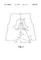
- FIG. 4is a schematic anteroposterior view of a vertebra showing the position of a guide pin in relation to a pedicle as the guide pin is about to enter the pedicle;
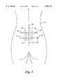
- FIG. 5is a schematic lateral view of the guide pin in relation to the pedicle as in FIG. 4;
- FIG. 6is an axial section of an expansible pedicle screw in accordance with the invention.
- FIG. 7is a top plan view of the expansible pedicle screw of FIG. 6;
- FIG. 8is an exploded view showing two expansible pedicle screws, a rigid connecting link, and adapters and nuts for securing the connecting link to the pedicle screws;
- FIG. 9is an elevational view of a sleeve for an obturator used in conjunction with an oval cannula in accordance with the invention.
- FIG. 10is an elevational view of the obturator
- FIG. 11is a longitudinal section through an assembly consisting of the sleeve and obturator of FIGS. 9 and 10;
- FIG. 12is a longitudinal section through an oval obturator in accordance with the invention.
- FIG. 13is a bottom plan view of the oval obturator of FIG. 12;
- FIG. 14is an elevational view of an oval cannula in accordance with the invention.
- FIG. 15is a bottom plan view of the oval cannula of FIG. 14;
- FIG. 16is a longitudinal section through an assembly of the oval cannula and obturator of FIGS. 12-15;
- FIG. 17is an elevational view of a trephine used with the oval obturator of FIG. 16.
- the CT scan depicted in FIG. 1shows a vertebral body 20 and a corresponding spinal process 22 in relation to the skin of the patient's back 24.
- a line 26is drawn on the CT scan through the spinal process and through the center of the vertebral body.
- An oblique line 28is drawn through the center of pedicle 30 to represent the desired path of entry of a guide pin.
- This linewill normally, although not necessarily, intersect line 26 approximately at the point at which line 26 passes through the anterior surface of the vertebral body.
- a measurementis then taken of the distance D between line 26 and the point 32 at which line 28 intersects the skin of the patient's back.
- the approach angle ⁇ between lines 26 and 28is also measured by means of a protractor and noted. The same procedure is carried out on a CT scan of each of the one or more other vertebrae which are to be fixed to the vertebra shown in FIG. 1.
- the patientis placed prone on a radiolucent frame and operating room table.
- the lumbar lordosisis flattened by flexion of the hips and the table, and care is taken to ensure that the patient is positioned symmetrically in relation to the frame and table.
- a C-arm fluoroscopeis positioned for anteroposterior radiographic visualization of the vertebral bodies at the surgical site.
- the C-armcan be tilted away from the pedicles, for example at an angle of 10 degrees.
- the radiographic observationmust be taken at the patient's midline.
- FIG. 2The radiographic view of the patient's spine, as seen through a fluoroscope, is depicted in FIG. 2, where two adjacent vertebral bodies 20 and 34 are shown, with an intervertebral disc 36 between them.
- the surgeonplaces a first straight, narrow, radiopaque element 38, for example an 18 gauge needle, over the spinal processes 22 and 40.
- the element 38When the element 38 is properly positioned, the surgeon draws a vertical line in ink directly on the skin of the patient's back at a location corresponding to the position of the element 38.
- Similar radiopaque elements 42 and 44are positioned over the centers of pedicles 30 and 45 respectively and arranged perpendicular to the direction of element 38. Horizontal ink lines are then drawn on the skin of the patient's back at locations corresponding to the locations of elements 42 and 44.
- a first entry point mark 52is made on horizontal line 48 at a distance D from the vertical line 46, the distance D having been previously measured on the CT scan through vertebral body 20 and pedicle 30.
- a second entry point mark 54is made on horizontal line 50 at a distance D' from vertical line 46, D' having been measured on a CT scan of vertebral body 34.
- a guide pin 56(shown in FIGS. 4 and 5) is inserted through the skin at the entry point 52 (FIG. 3) and passed through the fascia until its tip reaches the pedicle 30 of vertebral body 20.
- the position of the tip of the guide pin, which should be just lateral to boundary of the pedicle 30is verified by anteroposterior fluoroscopy as in FIG. 4, and appropriate adjustment can be made, if necessary.
- the position of the pin in the middle of the pedicle and parallel to the vertebral plateis verified by lateral fluoroscopic observation, as in FIG. 5, and again adjustments can be made if necessary.
- the guide pin 56is then hammered into the pedicle and into the vertebral body. This is done for the corresponding pedicles of each of the vertebrae to be fixated.
- a protective cannulamay be placed over the pedicle for protection and retraction of the paravertebral muscles while the medullary canal of the pedicle us being tapped. A sound is introduced to make certain that the cortex of the pedicle has not been violated.
- a guide pinis inserted and a pedicle screw is passed over the guide pin and turned by a wrench until it passes the mid point of the anteroposterior diameter of the vertebra.
- the protective cannulamay be left in place while the pedicle screw is being inserted.
- the lengthwise expansible pedicle screw 58which is shown in FIG. 6, comprises a shaft 60 having a distal portion 62 with threads adapted to be threaded into the medullary canal of a vertebral pedicle.
- the shaft 60has a centrally located, multifaceted head 64 for engagement by a wrench, for example a hex wrench, and a proximal portion 66 having machine screw threads 68.
- a tubular extension 70has internal threads 72, which are engaged with threads 68, so that rotation of the extension relative to the pedicle screw shaft 60, causes the extension to move lengthwise in one direction of the other, thereby increasing or decreasing the effective length of the pedicle screw 58.
- the threads 68 and 72should fit each other with a close tolerance so that the extension and shaft form a rigid unit when they are locked against relative rotation.
- the pedicle screw shaft 60has an central passage 74 extending lengthwise through it along its axis of elongation. This central passage enables the shaft to be placed over a guide pin.
- the upper end of the tubular extensionhas a threaded recess 76, with a bottom opening 78 aligned with passage 74, enabling the guide pin to pass through upper end of the extension.
- holes 80 and 82are provided in upper end face 84 of the extension 70 for receiving projections of a special wrench for rotating the extension.
- the upper end of the extension 70is also formed with wrench-engageable facets 85, which allow it to be held against rotation by a wrench as an adapter is attached to it.
- the facets 85form a hex nut which is smaller than hex head 64, thus allowing an elongated socket wrench to be inserted over the extension 70 for engagement with hex head 64.
- the threaded recess 76 of the extension 70is engageable with threads 86 of an adapter 88.
- the threads 86extend downward from a plate 90.
- the platehas notches 92 and 94 for engagement by a special wrench used to tighten it into secure engagement with the extension 70. These notches are at opposite ends of a raised, part 96 of the plate, the raised part having parallel edges 98 and 100.
- the raised part 96fits into a slot 102 in a link plate 104, and the adapter is secured to the link plate by a nut 106, which engages threads 108 which extend upwardly from the upper face of the adapter.
- the thickness of raised part 96 of the adapteris slightly less than the thickness of plate 104.
- Mating serrations 110 and 112are provided on the adapter and on the link plate respectively.
- FIG. 8also shows an identical lengthwise expansible pedicle screw 58', which is connectible to a second rectangular slot 102' in link plate 104 by means of an adapter 88' and a nut 106'.
- the guide pinsare removed.
- the extensionsare then rotated counterclockwise by a special wrench inserted into the holes 80 and 82 (see FIG. 7) until the outer ends of the extensions are at a level above the lumbar fascia.
- the adaptersare secured by a special wrench engaged with their notches 92, 94, 92' and 94'. After the adapters are secured to the extension, further adjustment, if necessary can be carried out by rotating the adapters and extensions together.
- the link plate 104is inserted and secured to the adapters. The link plate is located just above the surface of the lumbar fascia but below the skin.
- the procedure for locating the insertion points and for determining the angle of approach for the guide pinsprovides for accurate placement of the pins and of the pedicle screws, eliminates the distortion inherent in previous methods, reduces the likelihood of damage to the vertebral structure, and produces generally superior and consistent results.
- the location procedure, using a combination of CT scanning and anteroposterior radiographic observation,is also usable for accurate determination of the insertion point and approach angle for a biopsy cannula and for various other procedures in which a spinal instrument is inserted percutaneously.
- the lengthwise expansible pedicle screwis easily inserted and adjusted, and has as its principal advantage the fact that it eliminates the need to keep adapters of various lengths on hand for possible use in surgery.
- FIGS. 8-17For percutaneous spinal procedures such as decortication of vertebral plates, insertion of bone grafts, removal of herniated disc material and resection of nuclear tissue, the instrumentation depicted in FIGS. 8-17 can be used.
- An obturator 114shown in FIG. 10 is inserted into a guide sleeve 116, shown in FIG. 9, and the assembly of the obturator and sleeve is passed through the skin, subcutaneous tissue and muscle layer.
- the skin entry pointcan be determined by a combination of CT scanning and anteroposterior radiographic observation in the same manner as in the case of the insertion of pedicle screws.
- the entry point and angleare less critical. Typically, the entry point is about 10 cm. from the midline.
- the tip of the obturator 114is located either at the mid pedicle or lateral pedicle line.
- the tip of the obturator and sleeve assemblyshould be touching a line drawn posterior to the backs of the vertebrae adjacent to the intervertebral disc which is being accessed.
- An obturator 118having a longitudinal passage 120 and a blunt end 122, as shown in FIGS. 12 and 13, is inserted into a cannula 124, as shown in FIGS. 14 and 15.
- the cannulahas an oval cross-section, and the body of the obturator 118 also has an oval cross-section, conforming to the interior wall of the cannula.
- the major axis of the lumen of the cannulais preferably in the range of 7 to 12 mm, and the minor axis is preferably in the range of 3 to 5 mm.
- a typical cannulacan have a 3 ⁇ 7 mm lumen, a 5 ⁇ 12 lumen, or even a 3 ⁇ 12 or 5 ⁇ 7 lumen.
- the obturator 114is removed from the sleeve 116, and the assembly of the cannula and obturator, as shown in FIG. 16, is passed over the guide sleeve 116 and directed toward the annulus fibrosis. The obturator and guide sleeve are then removed, leaving the cannula 124 in place.
- a zero degree arthroscopeis inserted to inspect the annular surface to make certain that neural structures are not in the path of the inserted cannula.
- a trephine 126shown in FIG. 17, is inserted through the passage in the obturator to sever the annular fibers, and the oval cannula is passed through the fenestration formed by the trephine and engaged into the annular fibers.
- the trephinetypically has an outer diameter of 4.5 mm.
- the oval shape of the lumen of the cannulapermits simultaneous introduction of an arthroscope and forceps for removal of herniated disc material and resection of nuclear tissue.
- auxiliary cannulacan be of comparatively small diameter, e.g. 5 mm.
- Curettes and reamersare passed through the oval cannula while an arthroscope, e.g. a 30 or 70 degree arthroscope is introduced into the intervertebral disc through the auxiliary cannula from the opposite portal.
- Decortication of the vertebral platesis carried out under direct arthroscopic magnification and illumination.
- Autogenous boneharvested from the patient's ilium, is passed through the cannulae and packed between the vertebral plates of the proximal and distal vertebrae. Afterwards, the instruments are withdrawn and the wound is closed.
- the oval cannulahas the advantage that it allows plural instruments, e.g. an arthroscope and a forceps to extend through it at the same time, thereby eliminating the need for a separate cannula on the same side of the spine as in U.S. Pat. No. 5,395,317.
- the oval cross-sectionis also advantageous in that it accommodates decorticators having blades with comparatively large lateral dimensions, e.g. 7 mm. or 9 mm., for access to the concave surfaces of the vertebral plates.
- the decorticatorcan be rotated after the blades at its distal end pass beyond the opening at the distal end of the oval cannula.
- the use of the oval obturatorallows the oval cannula to be introduced readily with a minimum number of steps, and provides guidance for the trephine used to fenestrate the annulus fibrosis of the disc.
Landscapes
- Health & Medical Sciences (AREA)
- Orthopedic Medicine & Surgery (AREA)
- Life Sciences & Earth Sciences (AREA)
- Surgery (AREA)
- Neurology (AREA)
- Heart & Thoracic Surgery (AREA)
- Engineering & Computer Science (AREA)
- Biomedical Technology (AREA)
- Nuclear Medicine, Radiotherapy & Molecular Imaging (AREA)
- Medical Informatics (AREA)
- Molecular Biology (AREA)
- Animal Behavior & Ethology (AREA)
- General Health & Medical Sciences (AREA)
- Public Health (AREA)
- Veterinary Medicine (AREA)
- Dentistry (AREA)
- Oral & Maxillofacial Surgery (AREA)
- Surgical Instruments (AREA)
Abstract
Description
Claims (11)
Priority Applications (4)
| Application Number | Priority Date | Filing Date | Title |
|---|---|---|---|
| US08/893,286US5964761A (en) | 1997-07-15 | 1997-07-15 | Method and instruments for percutaneous arthroscopic disc removal, bone biopsy and fixation of vertebrae |
| US09/370,318US6175758B1 (en) | 1997-07-15 | 1999-08-09 | Method for percutaneous arthroscopic disc removal, bone biopsy and fixation of the vertebrae |
| US09/711,614US6596008B1 (en) | 1997-07-15 | 2000-11-13 | Method and instruments for percutaneous arthroscopic disc removal, bone biopsy and fixation of the vertebral |
| US11/186,016USRE44268E1 (en) | 1997-07-15 | 2005-07-20 | Method and instruments for percutaneous arthroscopic disc removal, bone biopsy and fixation of the vertebral |
Applications Claiming Priority (1)
| Application Number | Priority Date | Filing Date | Title |
|---|---|---|---|
| US08/893,286US5964761A (en) | 1997-07-15 | 1997-07-15 | Method and instruments for percutaneous arthroscopic disc removal, bone biopsy and fixation of vertebrae |
Related Child Applications (1)
| Application Number | Title | Priority Date | Filing Date |
|---|---|---|---|
| US09/370,318Continuation-In-PartUS6175758B1 (en) | 1997-07-15 | 1999-08-09 | Method for percutaneous arthroscopic disc removal, bone biopsy and fixation of the vertebrae |
Publications (1)
| Publication Number | Publication Date |
|---|---|
| US5964761Atrue US5964761A (en) | 1999-10-12 |
Family
ID=25401336
Family Applications (1)
| Application Number | Title | Priority Date | Filing Date |
|---|---|---|---|
| US08/893,286Expired - LifetimeUS5964761A (en) | 1997-07-15 | 1997-07-15 | Method and instruments for percutaneous arthroscopic disc removal, bone biopsy and fixation of vertebrae |
Country Status (1)
| Country | Link |
|---|---|
| US (1) | US5964761A (en) |
Cited By (130)
| Publication number | Priority date | Publication date | Assignee | Title |
|---|---|---|---|---|
| WO2001050967A1 (en)* | 2000-01-13 | 2001-07-19 | Camargo Paes Vera Lucia | Improved pedicular screw |
| US20020120273A1 (en)* | 1999-10-13 | 2002-08-29 | Needham Dusty Anna | Anterior cervical plating system and method |
| US20020161446A1 (en)* | 2000-08-08 | 2002-10-31 | Vincent Bryan | Method and apparatus for stereotactic impleantation |
| US20030004517A1 (en)* | 2000-09-11 | 2003-01-02 | Anderson D. Greg | Percutaneous technique and implant for expanding the spinal canal |
| US20030083592A1 (en)* | 2001-10-30 | 2003-05-01 | Tom Faciszewski | Biopsy/access tool with integrated biopsy device and access cannula and use thereof |
| US6558386B1 (en) | 2000-02-16 | 2003-05-06 | Trans1 Inc. | Axial spinal implant and method and apparatus for implanting an axial spinal implant within the vertebrae of the spine |
| US6558390B2 (en) | 2000-02-16 | 2003-05-06 | Axiamed, Inc. | Methods and apparatus for performing therapeutic procedures in the spine |
| US6575979B1 (en) | 2000-02-16 | 2003-06-10 | Axiamed, Inc. | Method and apparatus for providing posterior or anterior trans-sacral access to spinal vertebrae |
| US20040015172A1 (en)* | 2000-11-10 | 2004-01-22 | Lutz Biedermann | Bone screw |
| EP1405607A1 (en)* | 2002-10-04 | 2004-04-07 | BIEDERMANN MOTECH GmbH | Bone screw and bone screw with holding element |
| US6740090B1 (en) | 2000-02-16 | 2004-05-25 | Trans1 Inc. | Methods and apparatus for forming shaped axial bores through spinal vertebrae |
| US20040158246A1 (en)* | 1998-04-30 | 2004-08-12 | Sofamor S.N.C. | Anterior implant for the spine |
| US20040181231A1 (en)* | 2003-03-13 | 2004-09-16 | Centerpulse Spine-Tech, Inc. | Spinal access instrument |
| US20040220571A1 (en)* | 1998-04-30 | 2004-11-04 | Richard Assaker | Bone plate assembly |
| US20040267261A1 (en)* | 2001-11-22 | 2004-12-30 | Guillaume Derouet | Orthopedic implant consisting of a support structure provided with at least an orifice for passing through a fixing screw associated with a nut |
| US20050021031A1 (en)* | 1999-10-20 | 2005-01-27 | Foley Kevin T. | Instruments and methods for stabilization of bony structures |
| US20050038438A1 (en)* | 2003-08-11 | 2005-02-17 | Depuy Acromed, Inc. | Distraction screw |
| US6899716B2 (en) | 2000-02-16 | 2005-05-31 | Trans1, Inc. | Method and apparatus for spinal augmentation |
| WO2005089662A1 (en)* | 2004-03-23 | 2005-09-29 | Stryker Spine | Sphere and bone plate |
| US20050234456A1 (en)* | 2004-04-16 | 2005-10-20 | Malandain Hugues F | Plate system for minimally invasive support of the spine |
| US20050234452A1 (en)* | 2004-04-16 | 2005-10-20 | Malandain Hugues F | Subcutaneous support |
| US20060004398A1 (en)* | 2004-07-02 | 2006-01-05 | Binder Lawrence J Jr | Sequential dilator system |
| US20060074445A1 (en)* | 2004-09-29 | 2006-04-06 | David Gerber | Less invasive surgical system and methods |
| US20060089662A1 (en)* | 1998-08-20 | 2006-04-27 | Davison Thomas W | Method and apparatus for securing vertebrae |
| US20060149237A1 (en)* | 2004-12-30 | 2006-07-06 | Markworth Aaron D | Screw with deployable interlaced dual rods |
| US20060149252A1 (en)* | 2004-12-30 | 2006-07-06 | Markworth Aaron D | Bone anchorage screw with built-in hinged plate |
| US20060264934A1 (en)* | 2005-05-18 | 2006-11-23 | Medicinelodge, Inc. | System and method for orthopedic implant configuration |
| US20070055257A1 (en)* | 2005-06-30 | 2007-03-08 | Alex Vaccaro | Cannulated screw access system |
| US20070073405A1 (en)* | 2005-09-29 | 2007-03-29 | Dominique Verhulst | Motion segment repair system |
| US20070233079A1 (en)* | 2006-02-06 | 2007-10-04 | Stryker Spine | Rod contouring apparatus and method for percutaneous pedicle screw extension |
| US20080039840A1 (en)* | 2005-02-23 | 2008-02-14 | Pioneer Laboratories, Inc. | Minimally invasive surgical system |
| US20080234678A1 (en)* | 2007-03-20 | 2008-09-25 | Robert Gutierrez | Rod reducer |
| US20080262554A1 (en)* | 2004-10-20 | 2008-10-23 | Stanley Kyle Hayes | Dyanamic rod |
| US7473256B2 (en) | 2003-10-23 | 2009-01-06 | Trans1 Inc. | Method and apparatus for spinal distraction |
| US20090030465A1 (en)* | 2004-10-20 | 2009-01-29 | Moti Altarac | Dynamic rod |
| US20090082775A1 (en)* | 2006-10-25 | 2009-03-26 | Moti Altarac | Spondylolisthesis reduction system and method |
| US20090125047A1 (en)* | 2005-07-22 | 2009-05-14 | Joey Camia Reglos | Tissue splitter |
| US20090125032A1 (en)* | 2007-11-14 | 2009-05-14 | Gutierrez Robert C | Rod removal instrument |
| US7547317B2 (en) | 2000-02-16 | 2009-06-16 | Trans1 Inc. | Methods of performing procedures in the spine |
| US20090228045A1 (en)* | 2004-10-20 | 2009-09-10 | Stanley Kyle Hayes | Dynamic rod |
| US7601174B2 (en) | 2000-08-08 | 2009-10-13 | Warsaw Orthopedic, Inc. | Wear-resistant endoprosthetic devices |
| US7608077B2 (en) | 2000-02-16 | 2009-10-27 | Trans1 Inc. | Method and apparatus for spinal distraction and fusion |
| US20090326590A1 (en)* | 1999-10-13 | 2009-12-31 | Warsaw Orthopedic, Inc. | System and method for securing a plate to the spinal column |
| US7641657B2 (en) | 2003-06-10 | 2010-01-05 | Trans1, Inc. | Method and apparatus for providing posterior or anterior trans-sacral access to spinal vertebrae |
| US7648520B2 (en) | 2004-04-16 | 2010-01-19 | Kyphon Sarl | Pedicle screw assembly |
| US20100036423A1 (en)* | 2004-10-20 | 2010-02-11 | Stanley Kyle Hayes | Dynamic rod |
| US7666185B2 (en) | 2003-09-03 | 2010-02-23 | Synthes Usa, Llc | Translatable carriage fixation system |
| US20100078640A1 (en)* | 2008-10-01 | 2010-04-01 | Ping Mei | Thin Film Transistor Backplane |
| US7727263B2 (en) | 2000-02-16 | 2010-06-01 | Trans1, Inc. | Articulating spinal implant |
| US20100168751A1 (en)* | 2002-03-19 | 2010-07-01 | Anderson D Greg | Method, Implant & Instruments for Percutaneous Expansion of the Spinal Canal |
| US7758584B2 (en) | 2006-04-11 | 2010-07-20 | Synthes Usa, Llc | Minimally invasive fixation system |
| US20100280496A1 (en)* | 2009-05-01 | 2010-11-04 | Shippert Ronald D | Tissue transfer cannula |
| US7905908B2 (en) | 2000-02-16 | 2011-03-15 | Trans1, Inc. | Spinal mobility preservation method |
| US7909830B2 (en) | 2005-08-25 | 2011-03-22 | Synthes Usa, Llc | Methods of spinal fixation and instrumentation |
| US7935134B2 (en) | 2004-10-20 | 2011-05-03 | Exactech, Inc. | Systems and methods for stabilization of bone structures |
| US7955355B2 (en) | 2003-09-24 | 2011-06-07 | Stryker Spine | Methods and devices for improving percutaneous access in minimally invasive surgeries |
| US20110166610A1 (en)* | 2009-08-07 | 2011-07-07 | Moti Altarac | Systems and methods for stabilization of bone structures, including thorocolumbar stabilization systems and methods |
| US7998175B2 (en) | 2004-10-20 | 2011-08-16 | The Board Of Trustees Of The Leland Stanford Junior University | Systems and methods for posterior dynamic stabilization of the spine |
| US8002798B2 (en) | 2003-09-24 | 2011-08-23 | Stryker Spine | System and method for spinal implant placement |
| US20110230915A1 (en)* | 2002-03-19 | 2011-09-22 | Anderson D Greg | Device and Method for Expanding the Spinal Canal With Spinal Column Stabilization and Spinal Deformity Correction |
| US8025680B2 (en) | 2004-10-20 | 2011-09-27 | Exactech, Inc. | Systems and methods for posterior dynamic stabilization of the spine |
| US8043334B2 (en) | 2007-04-13 | 2011-10-25 | Depuy Spine, Inc. | Articulating facet fusion screw |
| US20110264098A1 (en)* | 2010-02-26 | 2011-10-27 | Cobbs Charles S | Minimally invasive systems, devices, and surgical methods for performing arthrodesis in the spine |
| US8092542B2 (en) | 2000-08-08 | 2012-01-10 | Warsaw Orthopedic, Inc. | Implantable joint prosthesis |
| US8133261B2 (en) | 2007-02-26 | 2012-03-13 | Depuy Spine, Inc. | Intra-facet fixation device and method of use |
| US8157847B2 (en) | 2000-09-11 | 2012-04-17 | David Greg Anderson | Percutaneous technique and implant for expanding the spinal canal |
| US8197513B2 (en) | 2007-04-13 | 2012-06-12 | Depuy Spine, Inc. | Facet fixation and fusion wedge and method of use |
| US8226690B2 (en) | 2005-07-22 | 2012-07-24 | The Board Of Trustees Of The Leland Stanford Junior University | Systems and methods for stabilization of bone structures |
| US8267969B2 (en) | 2004-10-20 | 2012-09-18 | Exactech, Inc. | Screw systems and methods for use in stabilization of bone structures |
| US8394129B2 (en) | 2011-03-10 | 2013-03-12 | Interventional Spine, Inc. | Method and apparatus for minimally invasive insertion of intervertebral implants |
| USRE44268E1 (en) | 1997-07-15 | 2013-06-04 | Zimmer Spine, Inc. | Method and instruments for percutaneous arthroscopic disc removal, bone biopsy and fixation of the vertebral |
| US8518087B2 (en) | 2011-03-10 | 2013-08-27 | Interventional Spine, Inc. | Method and apparatus for minimally invasive insertion of intervertebral implants |
| US8551141B2 (en) | 2006-08-23 | 2013-10-08 | Pioneer Surgical Technology, Inc. | Minimally invasive surgical system |
| US8894685B2 (en) | 2007-04-13 | 2014-11-25 | DePuy Synthes Products, LLC | Facet fixation and fusion screw and washer assembly and method of use |
| US9044277B2 (en) | 2010-07-12 | 2015-06-02 | DePuy Synthes Products, Inc. | Pedicular facet fusion screw with plate |
| US20150150615A1 (en)* | 2012-06-11 | 2015-06-04 | Merete Medical Gmbh | Bone Screw Arrangement with Variable Length |
| US9277928B2 (en) | 2013-03-11 | 2016-03-08 | Interventional Spine, Inc. | Method and apparatus for minimally invasive insertion of intervertebral implants |
| US9314274B2 (en) | 2011-05-27 | 2016-04-19 | DePuy Synthes Products, Inc. | Minimally invasive spinal fixation system including vertebral alignment features |
| US9381048B2 (en) | 2011-08-31 | 2016-07-05 | DePuy Synthes Products, Inc. | Devices and methods for cervical lateral fixation |
| US9387009B2 (en) | 2007-10-05 | 2016-07-12 | DePuy Synthes Products, Inc. | Dilation system and method of using the same |
| US9402663B2 (en) | 2010-04-23 | 2016-08-02 | DePuy Synthes Products, Inc. | Minimally invasive instrument set, devices and related methods |
| US9408646B2 (en) | 2003-09-03 | 2016-08-09 | DePuy Synthes Products, Inc. | Bone plate with captive clips |
| US9408716B1 (en) | 2013-12-06 | 2016-08-09 | Stryker European Holdings I, Llc | Percutaneous posterior spinal fusion implant construction and method |
| US9510875B2 (en) | 2013-03-14 | 2016-12-06 | Stryker European Holdings I, Llc | Systems and methods for percutaneous spinal fusion |
| US9522070B2 (en) | 2013-03-07 | 2016-12-20 | Interventional Spine, Inc. | Intervertebral implant |
| US9615866B1 (en) | 2004-10-18 | 2017-04-11 | Nuvasive, Inc. | Surgical fixation system and related methods |
| US9622735B2 (en) | 2000-08-01 | 2017-04-18 | Zimmer Spine, Inc. | Method for securing vertebrae |
| US9655665B2 (en) | 2007-07-03 | 2017-05-23 | Pioneer Surgical Technology, Inc. | Bone plate systems |
| US9744050B1 (en) | 2013-12-06 | 2017-08-29 | Stryker European Holdings I, Llc | Compression and distraction system for percutaneous posterior spinal fusion |
| US9808281B2 (en) | 2009-05-20 | 2017-11-07 | DePuy Synthes Products, Inc. | Patient-mounted retraction |
| US9814598B2 (en) | 2013-03-14 | 2017-11-14 | Quandary Medical, Llc | Spinal implants and implantation system |
| US9827020B2 (en) | 2013-03-14 | 2017-11-28 | Stryker European Holdings I, Llc | Percutaneous spinal cross link system and method |
| US9839530B2 (en) | 2007-06-26 | 2017-12-12 | DePuy Synthes Products, Inc. | Highly lordosed fusion cage |
| US9883951B2 (en) | 2012-08-30 | 2018-02-06 | Interventional Spine, Inc. | Artificial disc |
| US9895236B2 (en) | 2010-06-24 | 2018-02-20 | DePuy Synthes Products, Inc. | Enhanced cage insertion assembly |
| US9913727B2 (en) | 2015-07-02 | 2018-03-13 | Medos International Sarl | Expandable implant |
| US9931223B2 (en) | 2008-04-05 | 2018-04-03 | DePuy Synthes Products, Inc. | Expandable intervertebral implant |
| US9993349B2 (en) | 2002-06-27 | 2018-06-12 | DePuy Synthes Products, Inc. | Intervertebral disc |
| US9993353B2 (en) | 2013-03-14 | 2018-06-12 | DePuy Synthes Products, Inc. | Method and apparatus for minimally invasive insertion of intervertebral implants |
| US10034690B2 (en) | 2014-12-09 | 2018-07-31 | John A. Heflin | Spine alignment system |
| US10058433B2 (en) | 2012-07-26 | 2018-08-28 | DePuy Synthes Products, Inc. | Expandable implant |
| US10159514B2 (en) | 2011-12-23 | 2018-12-25 | Pioneer Surgical Technology, Inc. | Method of implanting a bone plate |
| US10159579B1 (en) | 2013-12-06 | 2018-12-25 | Stryker European Holdings I, Llc | Tubular instruments for percutaneous posterior spinal fusion systems and methods |
| US10226291B2 (en) | 2007-07-03 | 2019-03-12 | Pioneer Surgical Technology, Inc. | Bone plate system |
| US10390963B2 (en) | 2006-12-07 | 2019-08-27 | DePuy Synthes Products, Inc. | Intervertebral implant |
| US10398563B2 (en) | 2017-05-08 | 2019-09-03 | Medos International Sarl | Expandable cage |
| US10433977B2 (en) | 2008-01-17 | 2019-10-08 | DePuy Synthes Products, Inc. | Expandable intervertebral implant and associated method of manufacturing the same |
| US10500062B2 (en) | 2009-12-10 | 2019-12-10 | DePuy Synthes Products, Inc. | Bellows-like expandable interbody fusion cage |
| US10537436B2 (en) | 2016-11-01 | 2020-01-21 | DePuy Synthes Products, Inc. | Curved expandable cage |
| US10548741B2 (en) | 2010-06-29 | 2020-02-04 | DePuy Synthes Products, Inc. | Distractible intervertebral implant |
| US10595942B2 (en) | 2011-12-14 | 2020-03-24 | Stryker European Holdings I, Llc | Techniques for generating a bone plate design |
| US10888433B2 (en) | 2016-12-14 | 2021-01-12 | DePuy Synthes Products, Inc. | Intervertebral implant inserter and related methods |
| US10940016B2 (en) | 2017-07-05 | 2021-03-09 | Medos International Sarl | Expandable intervertebral fusion cage |
| US11259940B2 (en) | 2019-06-28 | 2022-03-01 | Mis Spine Ip, Llc | Systems and methods for percutaneous spinal interbody fusion (PSIF) |
| US11344424B2 (en) | 2017-06-14 | 2022-05-31 | Medos International Sarl | Expandable intervertebral implant and related methods |
| US11426286B2 (en) | 2020-03-06 | 2022-08-30 | Eit Emerging Implant Technologies Gmbh | Expandable intervertebral implant |
| US11426290B2 (en) | 2015-03-06 | 2022-08-30 | DePuy Synthes Products, Inc. | Expandable intervertebral implant, system, kit and method |
| US11446156B2 (en) | 2018-10-25 | 2022-09-20 | Medos International Sarl | Expandable intervertebral implant, inserter instrument, and related methods |
| US11452607B2 (en) | 2010-10-11 | 2022-09-27 | DePuy Synthes Products, Inc. | Expandable interspinous process spacer implant |
| US11510788B2 (en) | 2016-06-28 | 2022-11-29 | Eit Emerging Implant Technologies Gmbh | Expandable, angularly adjustable intervertebral cages |
| US11596523B2 (en) | 2016-06-28 | 2023-03-07 | Eit Emerging Implant Technologies Gmbh | Expandable and angularly adjustable articulating intervertebral cages |
| US11612491B2 (en) | 2009-03-30 | 2023-03-28 | DePuy Synthes Products, Inc. | Zero profile spinal fusion cage |
| US11752009B2 (en) | 2021-04-06 | 2023-09-12 | Medos International Sarl | Expandable intervertebral fusion cage |
| US11850160B2 (en) | 2021-03-26 | 2023-12-26 | Medos International Sarl | Expandable lordotic intervertebral fusion cage |
| US11877779B2 (en) | 2020-03-26 | 2024-01-23 | Xtant Medical Holdings, Inc. | Bone plate system |
| US11911287B2 (en) | 2010-06-24 | 2024-02-27 | DePuy Synthes Products, Inc. | Lateral spondylolisthesis reduction cage |
| USRE49973E1 (en) | 2013-02-28 | 2024-05-21 | DePuy Synthes Products, Inc. | Expandable intervertebral implant, system, kit and method |
| US12059168B2 (en) | 2021-06-16 | 2024-08-13 | Ludwig David Orozco Castillo | Systems and methods for ball probe ultrasonic foraminotomy |
| US12090064B2 (en) | 2022-03-01 | 2024-09-17 | Medos International Sarl | Stabilization members for expandable intervertebral implants, and related systems and methods |
| US12440346B2 (en) | 2023-03-31 | 2025-10-14 | DePuy Synthes Products, Inc. | Expandable intervertebral implant |
Citations (7)
| Publication number | Priority date | Publication date | Assignee | Title |
|---|---|---|---|---|
| US4545374A (en)* | 1982-09-03 | 1985-10-08 | Jacobson Robert E | Method and instruments for performing a percutaneous lumbar diskectomy |
| US4573448A (en)* | 1983-10-05 | 1986-03-04 | Pilling Co. | Method for decompressing herniated intervertebral discs |
| US5242443A (en)* | 1991-08-15 | 1993-09-07 | Smith & Nephew Dyonics, Inc. | Percutaneous fixation of vertebrae |
| US5395317A (en)* | 1991-10-30 | 1995-03-07 | Smith & Nephew Dyonics, Inc. | Unilateral biportal percutaneous surgical procedure |
| US5480440A (en)* | 1991-08-15 | 1996-01-02 | Smith & Nephew Richards, Inc. | Open surgical technique for vertebral fixation with subcutaneous fixators positioned between the skin and the lumbar fascia of a patient |
| US5540690A (en)* | 1991-07-15 | 1996-07-30 | Danek Group Inc. | Spinal fixation system |
| US5752955A (en)* | 1995-10-30 | 1998-05-19 | Fastenetix, L.L.C. | Sliding shaft variable length cross-link device for use with dual rod apparatus |
- 1997
- 1997-07-15USUS08/893,286patent/US5964761A/ennot_activeExpired - Lifetime
Patent Citations (7)
| Publication number | Priority date | Publication date | Assignee | Title |
|---|---|---|---|---|
| US4545374A (en)* | 1982-09-03 | 1985-10-08 | Jacobson Robert E | Method and instruments for performing a percutaneous lumbar diskectomy |
| US4573448A (en)* | 1983-10-05 | 1986-03-04 | Pilling Co. | Method for decompressing herniated intervertebral discs |
| US5540690A (en)* | 1991-07-15 | 1996-07-30 | Danek Group Inc. | Spinal fixation system |
| US5242443A (en)* | 1991-08-15 | 1993-09-07 | Smith & Nephew Dyonics, Inc. | Percutaneous fixation of vertebrae |
| US5480440A (en)* | 1991-08-15 | 1996-01-02 | Smith & Nephew Richards, Inc. | Open surgical technique for vertebral fixation with subcutaneous fixators positioned between the skin and the lumbar fascia of a patient |
| US5395317A (en)* | 1991-10-30 | 1995-03-07 | Smith & Nephew Dyonics, Inc. | Unilateral biportal percutaneous surgical procedure |
| US5752955A (en)* | 1995-10-30 | 1998-05-19 | Fastenetix, L.L.C. | Sliding shaft variable length cross-link device for use with dual rod apparatus |
Non-Patent Citations (18)
| Title |
|---|
| F. R. Magerl, "Stabilization of the Lower Thoracic and Lumbar Spine with External Skeletal Fixation", Clinical Orthopaedics and Related Research, pp. 125-142 (Oct. 1984). |
| F. R. Magerl, Stabilization of the Lower Thoracic and Lumbar Spine with External Skeletal Fixation , Clinical Orthopaedics and Related Research , pp. 125 142 (Oct. 1984).* |
| H. F. Leu et al., "Lumbar Percutaneous Endoscopic Interbody Fusion", Clinical Orthopaedics and Related Research 337:58-63 (Apr. 1997). |
| H. F. Leu et al., "Percutaneous Fusion of the Lumbar Spine: A Promising Technique", Spine: State of the Arts Review 6, pp. 593-604 (Sep. 1992). |
| H. F. Leu et al., Lumbar Percutaneous Endoscopic Interbody Fusion , Clinical Orthopaedics and Related Research 337:58 63 (Apr. 1997).* |
| H. F. Leu et al., Percutaneous Fusion of the Lumbar Spine: A Promising Technique , Spine: State of the Arts Review 6, pp. 593 604 (Sep. 1992).* |
| H.J. Leu et al., "Percutaneous Lumbar Restabilization", Arthroscopic Microdisectomy: Minimal Intervention in Spinal Surgery, pp. 123-125 (1991) No month (and/or year) of publication is available. |
| H.J. Leu et al., Percutaneous Lumbar Restabilization , Arthroscopic Microdisectomy: Minimal Intervention in Spinal Surgery , pp. 123 125 (1991) No month (and/or year) of publication is available.* |
| P. Kambin et al., "Arthroscopic Fusion of the Lumbosacral Spine", Lumbrosacral and Spinopelvic Fixation, Chapter 44, pp. 565-577 (1996) No month (and/or year) of publication is available. |
| P. Kambin et al., Arthroscopic Fusion of the Lumbosacral Spine , Lumbrosacral and Spinopelvic Fixation, Chapter 44, pp. 565 577 (1996) No month (and/or year) of publication is available.* |
| P. Kambin, "Arthroscopic Lubar Intervertebral Fusion", The Adult Spine: Principles and Practice, Chapter 95, pp. 2037-2046 (1997) No month (and/or year) of publication is available. |
| P. Kambin, "Arthroscopic Lumbar Interbody Fusion", Spine Care, Chapter 77, vol. 2 (1997) No month (and/or year) of publication is available. |
| P. Kambin, "Arthroscopic Techniques for Spinal Surgery", Operative Arthroscopy, 2nd Edition, pp. 1215-1225 (1996) No month (and/or year) of publication is available. |
| P. Kambin, "Posterolateral Percutaneous Lumbar Interbody Fusion", Arthroscopic Microdisectomy: Minimal Intervention in Spinal Surgery, pp. 117-121 (1991) No month (and/or year) of publication is available. |
| P. Kambin, Arthroscopic Lubar Intervertebral Fusion , The Adult Spine: Principles and Practice , Chapter 95, pp. 2037 2046 (1997) No month (and/or year) of publication is available.* |
| P. Kambin, Arthroscopic Lumbar Interbody Fusion , Spine Care , Chapter 77, vol. 2 (1997) No month (and/or year) of publication is available.* |
| P. Kambin, Arthroscopic Techniques for Spinal Surgery , Operative Arthroscopy, 2 nd Edition, pp. 1215 1225 (1996) No month (and/or year) of publication is available.* |
| P. Kambin, Posterolateral Percutaneous Lumbar Interbody Fusion , Arthroscopic Microdisectomy: Minimal Intervention in Spinal Surgery , pp. 117 121 (1991) No month (and/or year) of publication is available.* |
Cited By (344)
| Publication number | Priority date | Publication date | Assignee | Title |
|---|---|---|---|---|
| USRE44268E1 (en) | 1997-07-15 | 2013-06-04 | Zimmer Spine, Inc. | Method and instruments for percutaneous arthroscopic disc removal, bone biopsy and fixation of the vertebral |
| US20040158246A1 (en)* | 1998-04-30 | 2004-08-12 | Sofamor S.N.C. | Anterior implant for the spine |
| US8016864B2 (en) | 1998-04-30 | 2011-09-13 | Warsaw Orthopedic, Inc. | Anterior implant for the spine |
| US20100069968A1 (en)* | 1998-04-30 | 2010-03-18 | Sofamor S.N.C. | Anterior implant for the spine |
| US20040220571A1 (en)* | 1998-04-30 | 2004-11-04 | Richard Assaker | Bone plate assembly |
| US7799036B2 (en)* | 1998-08-20 | 2010-09-21 | Zimmer Spine, Inc. | Method and apparatus for securing vertebrae |
| US20060089662A1 (en)* | 1998-08-20 | 2006-04-27 | Davison Thomas W | Method and apparatus for securing vertebrae |
| US20020120273A1 (en)* | 1999-10-13 | 2002-08-29 | Needham Dusty Anna | Anterior cervical plating system and method |
| US20090326590A1 (en)* | 1999-10-13 | 2009-12-31 | Warsaw Orthopedic, Inc. | System and method for securing a plate to the spinal column |
| US8167919B2 (en) | 1999-10-13 | 2012-05-01 | Warsaw Orthopedic, Inc. | System and method for securing a plate to the spinal column |
| US9918754B2 (en) | 1999-10-20 | 2018-03-20 | Warsaw Orthopedic, Inc. | Instruments and methods for stabilization of bony structures |
| US7867259B2 (en) | 1999-10-20 | 2011-01-11 | Warsaw Orthopedic, Inc. | Instruments and methods for stabilization of bony structures |
| US7717944B2 (en) | 1999-10-20 | 2010-05-18 | Warsaw Orthopedic, Inc. | Instruments and methods for stabilization of bony structures |
| US8900275B2 (en) | 1999-10-20 | 2014-12-02 | Warsaw Orthopedic, Inc. | Instruments and methods for stabilization of bony structures |
| US7763055B2 (en) | 1999-10-20 | 2010-07-27 | Warsaw Orthopedic, Inc. | Instruments and methods for stabilization of bony structures |
| US7862595B2 (en) | 1999-10-20 | 2011-01-04 | Warsaw Orthopedic, Inc. | Instruments and methods for stabilization of bony structures |
| US9179948B2 (en) | 1999-10-20 | 2015-11-10 | Warsaw Orthopedic, Inc. | Instruments and methods for stabilization of bony structures |
| US9597127B2 (en) | 1999-10-20 | 2017-03-21 | Warsaw Orthopedic, Inc. | Instruments and methods for stabilization of bony structures |
| US20050021031A1 (en)* | 1999-10-20 | 2005-01-27 | Foley Kevin T. | Instruments and methods for stabilization of bony structures |
| US8961524B2 (en) | 1999-10-20 | 2015-02-24 | Warsaw Orthopedic, Inc. | Instruments and methods for stabilization of bony structures |
| US8361124B2 (en) | 1999-10-20 | 2013-01-29 | Warsaw Orthopedic, Inc. | Instruments and methods for stabilization of bony structures |
| US20060229614A1 (en)* | 1999-10-20 | 2006-10-12 | Foley Kevin T | Instruments and methods for stabilization of bony structures |
| US8721685B2 (en) | 1999-10-20 | 2014-05-13 | Kevin T. Foley | Instruments and methods for stabilization of bony structures |
| US8034055B2 (en) | 1999-12-13 | 2011-10-11 | Trans1 Inc. | Method and apparatus for providing access to a presacral space |
| WO2001050967A1 (en)* | 2000-01-13 | 2001-07-19 | Camargo Paes Vera Lucia | Improved pedicular screw |
| US7905908B2 (en) | 2000-02-16 | 2011-03-15 | Trans1, Inc. | Spinal mobility preservation method |
| US8105365B2 (en) | 2000-02-16 | 2012-01-31 | Trans1 Inc. | Methods and apparatus for performing therapeutic procedures in the spine |
| US7727263B2 (en) | 2000-02-16 | 2010-06-01 | Trans1, Inc. | Articulating spinal implant |
| US7744599B2 (en) | 2000-02-16 | 2010-06-29 | Trans1 Inc. | Articulating spinal implant |
| US7608077B2 (en) | 2000-02-16 | 2009-10-27 | Trans1 Inc. | Method and apparatus for spinal distraction and fusion |
| US6790210B1 (en) | 2000-02-16 | 2004-09-14 | Trans1, Inc. | Methods and apparatus for forming curved axial bores through spinal vertebrae |
| US8709087B2 (en) | 2000-02-16 | 2014-04-29 | Baxano Surgical, Inc. | Methods and apparatus for performing therapeutic procedures in the spine |
| US7569056B2 (en) | 2000-02-16 | 2009-08-04 | Trans1 Inc. | Methods and apparatus for forming shaped axial bores through spinal vertebrae |
| US6575979B1 (en) | 2000-02-16 | 2003-06-10 | Axiamed, Inc. | Method and apparatus for providing posterior or anterior trans-sacral access to spinal vertebrae |
| US6558390B2 (en) | 2000-02-16 | 2003-05-06 | Axiamed, Inc. | Methods and apparatus for performing therapeutic procedures in the spine |
| US7087058B2 (en) | 2000-02-16 | 2006-08-08 | Trans1, Inc. | Method and apparatus for providing posterior or anterior trans-sacral access to spinal vertebrae |
| US6921403B2 (en) | 2000-02-16 | 2005-07-26 | Trans1 Inc. | Method and apparatus for spinal distraction and fusion |
| US6899716B2 (en) | 2000-02-16 | 2005-05-31 | Trans1, Inc. | Method and apparatus for spinal augmentation |
| US7547317B2 (en) | 2000-02-16 | 2009-06-16 | Trans1 Inc. | Methods of performing procedures in the spine |
| US7794463B2 (en) | 2000-02-16 | 2010-09-14 | Trans1 Inc. | Methods and apparatus for performing therapeutic procedures in the spine |
| US8317867B2 (en) | 2000-02-16 | 2012-11-27 | Trans1 Inc. | Methods and apparatus for performing therapeutic procedures in the spine |
| US8292928B2 (en) | 2000-02-16 | 2012-10-23 | Trans1 Inc. | Method and apparatus for spinal distraction and fusion |
| US6558386B1 (en) | 2000-02-16 | 2003-05-06 | Trans1 Inc. | Axial spinal implant and method and apparatus for implanting an axial spinal implant within the vertebrae of the spine |
| US7309338B2 (en) | 2000-02-16 | 2007-12-18 | Trans1 Inc. | Methods and apparatus for performing therapeutic procedures in the spine |
| US6740090B1 (en) | 2000-02-16 | 2004-05-25 | Trans1 Inc. | Methods and apparatus for forming shaped axial bores through spinal vertebrae |
| US7905905B2 (en) | 2000-02-16 | 2011-03-15 | Trans1, Inc. | Spinal mobility preservation apparatus |
| US9622735B2 (en) | 2000-08-01 | 2017-04-18 | Zimmer Spine, Inc. | Method for securing vertebrae |
| US6949105B2 (en)* | 2000-08-08 | 2005-09-27 | Sdgi Holdings, Inc. | Method and apparatus for stereotactic implantation |
| US20020161446A1 (en)* | 2000-08-08 | 2002-10-31 | Vincent Bryan | Method and apparatus for stereotactic impleantation |
| US8092542B2 (en) | 2000-08-08 | 2012-01-10 | Warsaw Orthopedic, Inc. | Implantable joint prosthesis |
| US7601174B2 (en) | 2000-08-08 | 2009-10-13 | Warsaw Orthopedic, Inc. | Wear-resistant endoprosthetic devices |
| EP1307153B1 (en)* | 2000-08-08 | 2009-09-23 | Warsaw Orthopedic, Inc. | Apparatus for stereotactic implantation |
| US8814867B2 (en) | 2000-09-11 | 2014-08-26 | Innovative Surgical Designs, Inc. | Percutaneous technique and implant for expanding the spinal canal |
| US8157847B2 (en) | 2000-09-11 | 2012-04-17 | David Greg Anderson | Percutaneous technique and implant for expanding the spinal canal |
| US20030004517A1 (en)* | 2000-09-11 | 2003-01-02 | Anderson D. Greg | Percutaneous technique and implant for expanding the spinal canal |
| US7166107B2 (en)* | 2000-09-11 | 2007-01-23 | D. Greg Anderson | Percutaneous technique and implant for expanding the spinal canal |
| US8968372B2 (en) | 2000-11-10 | 2015-03-03 | Biedermann Technologies Gmbh & Co. Kg | Bone screw |
| US20040015172A1 (en)* | 2000-11-10 | 2004-01-22 | Lutz Biedermann | Bone screw |
| US8137389B2 (en)* | 2000-11-10 | 2012-03-20 | Biedermann Motech Gmbh & Co. Kg | Bone screw |
| US9468483B2 (en) | 2000-11-10 | 2016-10-18 | Biedermann Technologies Gmbh & Co. Kg | Bone screw |
| US20030083592A1 (en)* | 2001-10-30 | 2003-05-01 | Tom Faciszewski | Biopsy/access tool with integrated biopsy device and access cannula and use thereof |
| US7001342B2 (en) | 2001-10-30 | 2006-02-21 | Movdice Holding, Inc. | Biopsy/access tool with integrated biopsy device and access cannula and use thereof |
| US7331930B2 (en) | 2001-10-30 | 2008-02-19 | Movdicé Holding, Inc. | Biopsy/access tool |
| US20050222520A1 (en)* | 2001-10-30 | 2005-10-06 | Tom Faciszewski | Biopsy/access tool |
| US20040267261A1 (en)* | 2001-11-22 | 2004-12-30 | Guillaume Derouet | Orthopedic implant consisting of a support structure provided with at least an orifice for passing through a fixing screw associated with a nut |
| US7410496B2 (en)* | 2001-11-22 | 2008-08-12 | Dlp | Orthopedic implant consisting of a support structure provided with at least an orifice for passing through a fixing screw associated with a nut |
| US20100168751A1 (en)* | 2002-03-19 | 2010-07-01 | Anderson D Greg | Method, Implant & Instruments for Percutaneous Expansion of the Spinal Canal |
| US20110230915A1 (en)* | 2002-03-19 | 2011-09-22 | Anderson D Greg | Device and Method for Expanding the Spinal Canal With Spinal Column Stabilization and Spinal Deformity Correction |
| US9044279B2 (en)* | 2002-03-19 | 2015-06-02 | Innovative Surgical Designs, Inc. | Device and method for expanding the spinal canal with spinal column stabilization and spinal deformity correction |
| US9993349B2 (en) | 2002-06-27 | 2018-06-12 | DePuy Synthes Products, Inc. | Intervertebral disc |
| EP1844722A1 (en)* | 2002-10-04 | 2007-10-17 | BIEDERMANN MOTECH GmbH | Bone screw and bone screw with fixing device |
| US7736381B2 (en)* | 2002-10-04 | 2010-06-15 | Biedermann Motech Gmbh | Bone screw and bone screw with holding element |
| EP1405607A1 (en)* | 2002-10-04 | 2004-04-07 | BIEDERMANN MOTECH GmbH | Bone screw and bone screw with holding element |
| US20100286732A1 (en)* | 2002-10-04 | 2010-11-11 | Biedermann Motech Gmbh | Bone screw and bone screw with holding element |
| JP2004121841A (en)* | 2002-10-04 | 2004-04-22 | Biedermann Motech Gmbh | Bone screw, bone fixing device, and retaining element for screwing into bone screw |
| EP2314240A1 (en)* | 2002-10-04 | 2011-04-27 | Biedermann Motech GmbH | Bone screw and bone screw with holding element |
| US20040122431A1 (en)* | 2002-10-04 | 2004-06-24 | Lutz Biedermann | Bone screw and bone screw with holding element |
| KR101036872B1 (en)* | 2002-10-04 | 2011-05-25 | 비이더만 모테크 게엠베하 & 코. 카게 | Bone Screw with Bone Screw and Retention Member |
| US8267976B2 (en) | 2002-10-04 | 2012-09-18 | Biedermann Technologies Gmbh & Co. Kg | Bone screw and bone screw with holding element |
| US20040181231A1 (en)* | 2003-03-13 | 2004-09-16 | Centerpulse Spine-Tech, Inc. | Spinal access instrument |
| US7641659B2 (en) | 2003-03-13 | 2010-01-05 | Zimmer Spine, Inc. | Spinal access instrument |
| US7641657B2 (en) | 2003-06-10 | 2010-01-05 | Trans1, Inc. | Method and apparatus for providing posterior or anterior trans-sacral access to spinal vertebrae |
| US20050038438A1 (en)* | 2003-08-11 | 2005-02-17 | Depuy Acromed, Inc. | Distraction screw |
| US7708766B2 (en) | 2003-08-11 | 2010-05-04 | Depuy Spine, Inc. | Distraction screw |
| US9408646B2 (en) | 2003-09-03 | 2016-08-09 | DePuy Synthes Products, Inc. | Bone plate with captive clips |
| US8262659B2 (en) | 2003-09-03 | 2012-09-11 | Synthes Usa, Llc | Translatable carriage fixation system |
| US9414870B2 (en) | 2003-09-03 | 2016-08-16 | DePuy Synthes Products, Inc. | Translatable carriage fixation system |
| US7666185B2 (en) | 2003-09-03 | 2010-02-23 | Synthes Usa, Llc | Translatable carriage fixation system |
| US10368927B2 (en) | 2003-09-03 | 2019-08-06 | DePuy Synthes Products, Inc. | Bone plate with captive clips |
| US7955355B2 (en) | 2003-09-24 | 2011-06-07 | Stryker Spine | Methods and devices for improving percutaneous access in minimally invasive surgeries |
| US8685063B2 (en) | 2003-09-24 | 2014-04-01 | Stryker Spine | Methods and devices for improving percutaneous access in minimally invasive surgeries |
| US8002798B2 (en) | 2003-09-24 | 2011-08-23 | Stryker Spine | System and method for spinal implant placement |
| US9700357B2 (en) | 2003-09-24 | 2017-07-11 | Stryker European Holdings I, Llc | Methods and devices for improving percutaneous access in minimally invasive surgeries |
| USRE46432E1 (en) | 2003-09-24 | 2017-06-13 | Stryker European Holdings I, Llc | System and method for spinal implant placement |
| USRE45338E1 (en) | 2003-09-24 | 2015-01-13 | Stryker Spine | System and method for spinal implant placement |
| USRE45676E1 (en) | 2003-09-24 | 2015-09-29 | Stryker Spine | System and method for spinal implant placement |
| US20110238120A1 (en)* | 2003-09-24 | 2011-09-29 | Stryker Spine | Methods and devices for improving percutaneous access in minimally invasive surgeries |
| US7799033B2 (en) | 2003-10-23 | 2010-09-21 | Trans1 Inc. | Access kits for enabling axial access and procedures in the spine |
| US7500977B2 (en) | 2003-10-23 | 2009-03-10 | Trans1 Inc. | Method and apparatus for manipulating material in the spine |
| US7530993B2 (en) | 2003-10-23 | 2009-05-12 | Trans1 Inc. | Method of spinal fixation |
| US7914535B2 (en) | 2003-10-23 | 2011-03-29 | Trans1 Inc. | Method and apparatus for manipulating material in the spine |
| US8052613B2 (en) | 2003-10-23 | 2011-11-08 | Trans1 Inc. | Spinal nucleus extraction tool |
| US8308777B2 (en) | 2003-10-23 | 2012-11-13 | Trans1 Inc. | Method and apparatus for removable spinal implant extending between at least two adjacent vertebral bodies |
| US7799032B2 (en) | 2003-10-23 | 2010-09-21 | Trans1 Inc. | Guide pin introducer for guiding instrumentation through soft tissue to a point on the spine |
| US7473256B2 (en) | 2003-10-23 | 2009-01-06 | Trans1 Inc. | Method and apparatus for spinal distraction |
| US7763025B2 (en) | 2003-10-23 | 2010-07-27 | Trans1 Inc. | Spinal fusion kit for guiding instrumentation through soft tissue to a point on the spine |
| US7588574B2 (en) | 2003-10-23 | 2009-09-15 | Trans1 Inc. | Kits for enabling axial access and procedures in the spine |
| US7740633B2 (en) | 2003-10-23 | 2010-06-22 | Trans1 Inc. | Guide pin for guiding instrumentation along a soft tissue tract to a point on the spine |
| USRE47348E1 (en) | 2003-11-08 | 2019-04-16 | Stryker European Holdings I, Llc | System and method for spinal implant placement |
| US10993747B2 (en) | 2003-11-08 | 2021-05-04 | Stryker European Operations Holdings Llc | Methods and devices for improving percutaneous access in minimally invasive surgeries |
| USRE49432E1 (en) | 2003-11-08 | 2023-02-28 | Stryker European Operations Holdings Llc | System and method for spinal implant placement |
| USRE48376E1 (en) | 2003-11-08 | 2021-01-05 | Stryker European Operations Holdings Llc | System and method for spinal implant placement |
| US10143502B2 (en) | 2003-11-08 | 2018-12-04 | Stryker European Holdings I, Llc | Methods and devices for improving percutaneous access in minimally invasive surgeries |
| FR2867962A1 (en)* | 2004-03-23 | 2005-09-30 | Stryker Spine Sa | OSTEOSYNTHESIS AND SPHERICAL PLATE |
| US7491221B2 (en) | 2004-03-23 | 2009-02-17 | Stryker Spine | Modular polyaxial bone screw and plate |
| US20050216001A1 (en)* | 2004-03-23 | 2005-09-29 | Stryker Spine | Sphere and bone plate |
| WO2005089662A1 (en)* | 2004-03-23 | 2005-09-29 | Stryker Spine | Sphere and bone plate |
| US7648520B2 (en) | 2004-04-16 | 2010-01-19 | Kyphon Sarl | Pedicle screw assembly |
| US20050234456A1 (en)* | 2004-04-16 | 2005-10-20 | Malandain Hugues F | Plate system for minimally invasive support of the spine |
| US20100076494A1 (en)* | 2004-04-16 | 2010-03-25 | Kyphon Sarl | Pedicle screw assembly |
| US20050234452A1 (en)* | 2004-04-16 | 2005-10-20 | Malandain Hugues F | Subcutaneous support |
| US7618418B2 (en) | 2004-04-16 | 2009-11-17 | Kyphon Sarl | Plate system for minimally invasive support of the spine |
| US7524323B2 (en)* | 2004-04-16 | 2009-04-28 | Kyphon Sarl | Subcutaneous support |
| US20060004398A1 (en)* | 2004-07-02 | 2006-01-05 | Binder Lawrence J Jr | Sequential dilator system |
| US7666189B2 (en) | 2004-09-29 | 2010-02-23 | Synthes Usa, Llc | Less invasive surgical system and methods |
| US20060074445A1 (en)* | 2004-09-29 | 2006-04-06 | David Gerber | Less invasive surgical system and methods |
| US9615866B1 (en) | 2004-10-18 | 2017-04-11 | Nuvasive, Inc. | Surgical fixation system and related methods |
| US7998175B2 (en) | 2004-10-20 | 2011-08-16 | The Board Of Trustees Of The Leland Stanford Junior University | Systems and methods for posterior dynamic stabilization of the spine |
| US8267969B2 (en) | 2004-10-20 | 2012-09-18 | Exactech, Inc. | Screw systems and methods for use in stabilization of bone structures |
| US20090030465A1 (en)* | 2004-10-20 | 2009-01-29 | Moti Altarac | Dynamic rod |
| US20100036423A1 (en)* | 2004-10-20 | 2010-02-11 | Stanley Kyle Hayes | Dynamic rod |
| US8162985B2 (en) | 2004-10-20 | 2012-04-24 | The Board Of Trustees Of The Leland Stanford Junior University | Systems and methods for posterior dynamic stabilization of the spine |
| US7935134B2 (en) | 2004-10-20 | 2011-05-03 | Exactech, Inc. | Systems and methods for stabilization of bone structures |
| US20090228045A1 (en)* | 2004-10-20 | 2009-09-10 | Stanley Kyle Hayes | Dynamic rod |
| US8551142B2 (en) | 2004-10-20 | 2013-10-08 | Exactech, Inc. | Methods for stabilization of bone structures |
| US8025680B2 (en) | 2004-10-20 | 2011-09-27 | Exactech, Inc. | Systems and methods for posterior dynamic stabilization of the spine |
| US20080262554A1 (en)* | 2004-10-20 | 2008-10-23 | Stanley Kyle Hayes | Dyanamic rod |
| US8075595B2 (en) | 2004-10-20 | 2011-12-13 | The Board Of Trustees Of The Leland Stanford Junior University | Systems and methods for posterior dynamic stabilization of the spine |
| US20060149237A1 (en)* | 2004-12-30 | 2006-07-06 | Markworth Aaron D | Screw with deployable interlaced dual rods |
| US7811311B2 (en) | 2004-12-30 | 2010-10-12 | Warsaw Orthopedic, Inc. | Screw with deployable interlaced dual rods |
| US7789899B2 (en) | 2004-12-30 | 2010-09-07 | Warsaw Orthopedic, Inc. | Bone anchorage screw with built-in hinged plate |
| US20060149252A1 (en)* | 2004-12-30 | 2006-07-06 | Markworth Aaron D | Bone anchorage screw with built-in hinged plate |
| US20080039839A1 (en)* | 2005-02-23 | 2008-02-14 | Pioneer Laboratories, Inc. | Minimally invasive surgical system |
| US12232782B2 (en) | 2005-02-23 | 2025-02-25 | Xtant Medical Holdings, Inc. | Minimally invasive surgical system |
| US7922727B2 (en) | 2005-02-23 | 2011-04-12 | Pioneer Surgical Technology, Inc. | Minimally invasive surgical system |
| US9730738B2 (en) | 2005-02-23 | 2017-08-15 | Pioneer Surgical Technology, Inc. | Minimally invasive surgical system |
| US8192439B2 (en) | 2005-02-23 | 2012-06-05 | Pioneer Surgical Technology, Inc. | Minimally invasive surgical system |
| US9033988B2 (en) | 2005-02-23 | 2015-05-19 | Pioneer Surgical Technology, Inc. | Minimally invasive surgical system |
| US8641719B2 (en) | 2005-02-23 | 2014-02-04 | Pioneer Surgical Technology, Inc. | Minimally invasive surgical system |
| US10194959B2 (en) | 2005-02-23 | 2019-02-05 | Pioneer Surgical Technology, Inc. | Minimally invasive surgical system |
| US7918878B2 (en) | 2005-02-23 | 2011-04-05 | Pioneer Surgical Technology, Inc. | Minimally invasive surgical system |
| US20080039840A1 (en)* | 2005-02-23 | 2008-02-14 | Pioneer Laboratories, Inc. | Minimally invasive surgical system |
| US11116553B2 (en) | 2005-02-23 | 2021-09-14 | Pioneer Surgical Technology, Inc. | Minimally invasive surgical system |
| US10898251B2 (en)* | 2005-05-18 | 2021-01-26 | Stryker European Operations Holdings Llc | System and method for orthopedic implant configuration |
| US20210128215A1 (en)* | 2005-05-18 | 2021-05-06 | Stryker European Operations Holdings Llc | System And Method For Orthopedic Implant Configuration |
| US9895182B2 (en) | 2005-05-18 | 2018-02-20 | Stryker European Holdings I. Llc | System and method for orthopedic implant configuration |
| US20180243024A1 (en)* | 2005-05-18 | 2018-08-30 | Stryker European Holdings I, Llc | System and method for orthopedic implant configuration |
| US20060264934A1 (en)* | 2005-05-18 | 2006-11-23 | Medicinelodge, Inc. | System and method for orthopedic implant configuration |
| US8177817B2 (en) | 2005-05-18 | 2012-05-15 | Stryker Spine | System and method for orthopedic implant configuration |
| US11596461B2 (en)* | 2005-05-18 | 2023-03-07 | Stryker European Operations Holdings Llc | System and method for orthopedic implant configuration |
| US20070055257A1 (en)* | 2005-06-30 | 2007-03-08 | Alex Vaccaro | Cannulated screw access system |
| US20090125047A1 (en)* | 2005-07-22 | 2009-05-14 | Joey Camia Reglos | Tissue splitter |
| US8226690B2 (en) | 2005-07-22 | 2012-07-24 | The Board Of Trustees Of The Leland Stanford Junior University | Systems and methods for stabilization of bone structures |
| US8523865B2 (en) | 2005-07-22 | 2013-09-03 | Exactech, Inc. | Tissue splitter |
| US7909830B2 (en) | 2005-08-25 | 2011-03-22 | Synthes Usa, Llc | Methods of spinal fixation and instrumentation |
| US8808296B2 (en) | 2005-08-25 | 2014-08-19 | DePuy Synthes Products, LLC | Methods of spinal fixation and instrumentation |
| US7993376B2 (en)* | 2005-09-29 | 2011-08-09 | Depuy Spine, Inc. | Methods of implanting a motion segment repair system |
| US8864772B2 (en) | 2005-09-29 | 2014-10-21 | DePuy Synthes Products, LLC | Motion segment repair systems and methods |
| US20070073405A1 (en)* | 2005-09-29 | 2007-03-29 | Dominique Verhulst | Motion segment repair system |
| US20110172722A1 (en)* | 2005-09-29 | 2011-07-14 | Depuy Spine, Inc. | Motion Segment Repair Systems and Methods |
| US9247977B2 (en) | 2006-02-06 | 2016-02-02 | Stryker European Holdings I, Llc | Rod contouring apparatus for percutaneous pedicle screw extension |
| US10070936B2 (en) | 2006-02-06 | 2018-09-11 | Stryker European Holdings I, Llc | Rod contouring apparatus for percutaneous pedicle screw extension |
| US20070233079A1 (en)* | 2006-02-06 | 2007-10-04 | Stryker Spine | Rod contouring apparatus and method for percutaneous pedicle screw extension |
| US9655685B2 (en) | 2006-02-06 | 2017-05-23 | Stryker European Holdings I, Llc | Rod contouring apparatus for percutaneous pedicle screw extension |
| US8894655B2 (en) | 2006-02-06 | 2014-11-25 | Stryker Spine | Rod contouring apparatus and method for percutaneous pedicle screw extension |
| US10765488B2 (en) | 2006-02-06 | 2020-09-08 | Stryker European Holdings I, Llc | Rod contouring apparatus for percutaneous pedicle screw extension |
| US9119684B2 (en) | 2006-02-06 | 2015-09-01 | Stryker Spine | Rod contouring method for percutaneous pedicle screw extension |
| US8979851B2 (en) | 2006-02-06 | 2015-03-17 | Stryker Spine | Rod contouring apparatus for percutaneous pedicle screw extension |
| US10441325B2 (en) | 2006-04-11 | 2019-10-15 | DePuy Synthes Products, Inc. | Minimally invasive fixation system |
| US7758584B2 (en) | 2006-04-11 | 2010-07-20 | Synthes Usa, Llc | Minimally invasive fixation system |
| US9498262B2 (en) | 2006-04-11 | 2016-11-22 | DePuy Synthes Products, Inc. | Minimally invasive fixation system |
| US8551141B2 (en) | 2006-08-23 | 2013-10-08 | Pioneer Surgical Technology, Inc. | Minimally invasive surgical system |
| US20090082775A1 (en)* | 2006-10-25 | 2009-03-26 | Moti Altarac | Spondylolisthesis reduction system and method |
| US11660206B2 (en) | 2006-12-07 | 2023-05-30 | DePuy Synthes Products, Inc. | Intervertebral implant |
| US11712345B2 (en) | 2006-12-07 | 2023-08-01 | DePuy Synthes Products, Inc. | Intervertebral implant |
| US11273050B2 (en) | 2006-12-07 | 2022-03-15 | DePuy Synthes Products, Inc. | Intervertebral implant |
| US11432942B2 (en) | 2006-12-07 | 2022-09-06 | DePuy Synthes Products, Inc. | Intervertebral implant |
| US10583015B2 (en) | 2006-12-07 | 2020-03-10 | DePuy Synthes Products, Inc. | Intervertebral implant |
| US11497618B2 (en) | 2006-12-07 | 2022-11-15 | DePuy Synthes Products, Inc. | Intervertebral implant |
| US10390963B2 (en) | 2006-12-07 | 2019-08-27 | DePuy Synthes Products, Inc. | Intervertebral implant |
| US11642229B2 (en) | 2006-12-07 | 2023-05-09 | DePuy Synthes Products, Inc. | Intervertebral implant |
| US10398566B2 (en) | 2006-12-07 | 2019-09-03 | DePuy Synthes Products, Inc. | Intervertebral implant |
| US8133261B2 (en) | 2007-02-26 | 2012-03-13 | Depuy Spine, Inc. | Intra-facet fixation device and method of use |
| US8096996B2 (en) | 2007-03-20 | 2012-01-17 | Exactech, Inc. | Rod reducer |
| US20080234678A1 (en)* | 2007-03-20 | 2008-09-25 | Robert Gutierrez | Rod reducer |
| US8894685B2 (en) | 2007-04-13 | 2014-11-25 | DePuy Synthes Products, LLC | Facet fixation and fusion screw and washer assembly and method of use |
| US8197513B2 (en) | 2007-04-13 | 2012-06-12 | Depuy Spine, Inc. | Facet fixation and fusion wedge and method of use |
| US8043334B2 (en) | 2007-04-13 | 2011-10-25 | Depuy Spine, Inc. | Articulating facet fusion screw |
| US9839530B2 (en) | 2007-06-26 | 2017-12-12 | DePuy Synthes Products, Inc. | Highly lordosed fusion cage |
| US10973652B2 (en) | 2007-06-26 | 2021-04-13 | DePuy Synthes Products, Inc. | Highly lordosed fusion cage |
| US11622868B2 (en) | 2007-06-26 | 2023-04-11 | DePuy Synthes Products, Inc. | Highly lordosed fusion cage |
| US9655665B2 (en) | 2007-07-03 | 2017-05-23 | Pioneer Surgical Technology, Inc. | Bone plate systems |
| US10226291B2 (en) | 2007-07-03 | 2019-03-12 | Pioneer Surgical Technology, Inc. | Bone plate system |
| US10898247B2 (en) | 2007-07-03 | 2021-01-26 | Pioneer Surgical Technology, Inc. | Bone plate system |
| US10194895B2 (en) | 2007-10-05 | 2019-02-05 | DePuy Synhes Products, Inc. | Dilation system and method of using the same |
| US9387009B2 (en) | 2007-10-05 | 2016-07-12 | DePuy Synthes Products, Inc. | Dilation system and method of using the same |
| US9737290B2 (en) | 2007-10-05 | 2017-08-22 | DePuy Synthes Products, Inc. | Dilation system and method of using the same |
| US11737743B2 (en) | 2007-10-05 | 2023-08-29 | DePuy Synthes Products, Inc. | Dilation system and method of using the same |
| US9974533B2 (en) | 2007-10-05 | 2018-05-22 | DePuy Synthes Products, Inc. | Dilation system and method of using the same |
| US10925594B2 (en) | 2007-10-05 | 2021-02-23 | DePuy Synthes Products, Inc. | Dilation system and method of using the same |
| US20090125032A1 (en)* | 2007-11-14 | 2009-05-14 | Gutierrez Robert C | Rod removal instrument |
| US10449058B2 (en) | 2008-01-17 | 2019-10-22 | DePuy Synthes Products, Inc. | Expandable intervertebral implant and associated method of manufacturing the same |
| US11737881B2 (en) | 2008-01-17 | 2023-08-29 | DePuy Synthes Products, Inc. | Expandable intervertebral implant and associated method of manufacturing the same |
| US10433977B2 (en) | 2008-01-17 | 2019-10-08 | DePuy Synthes Products, Inc. | Expandable intervertebral implant and associated method of manufacturing the same |
| US11701234B2 (en) | 2008-04-05 | 2023-07-18 | DePuy Synthes Products, Inc. | Expandable intervertebral implant |
| US11712341B2 (en) | 2008-04-05 | 2023-08-01 | DePuy Synthes Products, Inc. | Expandable intervertebral implant |
| US11602438B2 (en) | 2008-04-05 | 2023-03-14 | DePuy Synthes Products, Inc. | Expandable intervertebral implant |
| US9993350B2 (en) | 2008-04-05 | 2018-06-12 | DePuy Synthes Products, Inc. | Expandable intervertebral implant |
| US11712342B2 (en) | 2008-04-05 | 2023-08-01 | DePuy Synthes Products, Inc. | Expandable intervertebral implant |
| US10449056B2 (en) | 2008-04-05 | 2019-10-22 | DePuy Synthes Products, Inc. | Expandable intervertebral implant |
| US11707359B2 (en) | 2008-04-05 | 2023-07-25 | DePuy Synthes Products, Inc. | Expandable intervertebral implant |
| US12023255B2 (en) | 2008-04-05 | 2024-07-02 | DePuy Synthes Products, Inc. | Expandable inter vertebral implant |
| US9931223B2 (en) | 2008-04-05 | 2018-04-03 | DePuy Synthes Products, Inc. | Expandable intervertebral implant |
| US12011361B2 (en) | 2008-04-05 | 2024-06-18 | DePuy Synthes Products, Inc. | Expandable intervertebral implant |
| US11617655B2 (en) | 2008-04-05 | 2023-04-04 | DePuy Synthes Products, Inc. | Expandable intervertebral implant |
| US20100078640A1 (en)* | 2008-10-01 | 2010-04-01 | Ping Mei | Thin Film Transistor Backplane |
| US12097124B2 (en) | 2009-03-30 | 2024-09-24 | DePuy Synthes Products, Inc. | Zero profile spinal fusion cage |
| US11612491B2 (en) | 2009-03-30 | 2023-03-28 | DePuy Synthes Products, Inc. | Zero profile spinal fusion cage |
| US20100280496A1 (en)* | 2009-05-01 | 2010-11-04 | Shippert Ronald D | Tissue transfer cannula |
| US8333740B2 (en) | 2009-05-01 | 2012-12-18 | Shippert Ronald D | Tissue transfer cannula |
| US9808281B2 (en) | 2009-05-20 | 2017-11-07 | DePuy Synthes Products, Inc. | Patient-mounted retraction |
| US10993739B2 (en) | 2009-05-20 | 2021-05-04 | DePuy Synthes Products, Inc. | Patient-mounted retraction |
| US12349936B2 (en) | 2009-05-20 | 2025-07-08 | DePuy Synthes Products, Inc. | Patient-mounted retraction |
| US20110166610A1 (en)* | 2009-08-07 | 2011-07-07 | Moti Altarac | Systems and methods for stabilization of bone structures, including thorocolumbar stabilization systems and methods |
| US11607321B2 (en) | 2009-12-10 | 2023-03-21 | DePuy Synthes Products, Inc. | Bellows-like expandable interbody fusion cage |
| US10500062B2 (en) | 2009-12-10 | 2019-12-10 | DePuy Synthes Products, Inc. | Bellows-like expandable interbody fusion cage |
| US20110264098A1 (en)* | 2010-02-26 | 2011-10-27 | Cobbs Charles S | Minimally invasive systems, devices, and surgical methods for performing arthrodesis in the spine |
| US10888360B2 (en) | 2010-04-23 | 2021-01-12 | DePuy Synthes Products, Inc. | Minimally invasive instrument set, devices, and related methods |
| US11389213B2 (en) | 2010-04-23 | 2022-07-19 | DePuy Synthes Products, Inc. | Minimally invasive instrument set, devices, and related methods |
| US9402663B2 (en) | 2010-04-23 | 2016-08-02 | DePuy Synthes Products, Inc. | Minimally invasive instrument set, devices and related methods |
| US11911287B2 (en) | 2010-06-24 | 2024-02-27 | DePuy Synthes Products, Inc. | Lateral spondylolisthesis reduction cage |
| US12318304B2 (en) | 2010-06-24 | 2025-06-03 | DePuy Synthes Products, Inc. | Lateral spondylolisthesis reduction cage |
| US9895236B2 (en) | 2010-06-24 | 2018-02-20 | DePuy Synthes Products, Inc. | Enhanced cage insertion assembly |
| US10966840B2 (en) | 2010-06-24 | 2021-04-06 | DePuy Synthes Products, Inc. | Enhanced cage insertion assembly |
| US11872139B2 (en) | 2010-06-24 | 2024-01-16 | DePuy Synthes Products, Inc. | Enhanced cage insertion assembly |
| US10548741B2 (en) | 2010-06-29 | 2020-02-04 | DePuy Synthes Products, Inc. | Distractible intervertebral implant |
| US11654033B2 (en) | 2010-06-29 | 2023-05-23 | DePuy Synthes Products, Inc. | Distractible intervertebral implant |
| US9089372B2 (en) | 2010-07-12 | 2015-07-28 | DePuy Synthes Products, Inc. | Pedicular facet fusion screw with plate |
| US9044277B2 (en) | 2010-07-12 | 2015-06-02 | DePuy Synthes Products, Inc. | Pedicular facet fusion screw with plate |
| US11452607B2 (en) | 2010-10-11 | 2022-09-27 | DePuy Synthes Products, Inc. | Expandable interspinous process spacer implant |
| US10743913B2 (en) | 2011-03-10 | 2020-08-18 | DePuy Synthes Products, Inc. | Method and apparatus for minimally invasive insertion of intervertebral implants |
| US11547442B2 (en) | 2011-03-10 | 2023-01-10 | DePuy Synthes Products, Inc. | Method and apparatus for minimally invasive insertion of intervertebral implants |
| US10744004B2 (en) | 2011-03-10 | 2020-08-18 | DePuy Synthes Products, Inc. | Method and apparatus for minimally invasive insertion of intervertebral implants |
| US10743915B2 (en) | 2011-03-10 | 2020-08-18 | DePuy Synthes Products, Inc. | Method and apparatus for minimally invasive insertion of intervertebral implants |
| US10182842B2 (en) | 2011-03-10 | 2019-01-22 | DePuy Synthes Products, Inc. | Method and apparatus for minimally invasive insertion of intervertebral implants |
| US8518087B2 (en) | 2011-03-10 | 2013-08-27 | Interventional Spine, Inc. | Method and apparatus for minimally invasive insertion of intervertebral implants |
| US10743914B2 (en) | 2011-03-10 | 2020-08-18 | DePuy Snythes Products, Inc. | Method and apparatus for minimally invasive insertion of intervertebral implants |
| US10736661B2 (en) | 2011-03-10 | 2020-08-11 | DePuy Synthes Products, Inc. | Method and apparatus for minimally invasive insertion of intervertebral implants |
| US11484418B2 (en) | 2011-03-10 | 2022-11-01 | DePuy Synthes Products, Inc. | Method and apparatus for minimally invasive insertion of intervertebral implants |
| US10111759B2 (en) | 2011-03-10 | 2018-10-30 | DePuy Synthes Products, Inc. | Method and apparatus for minimally invasive insertion of intervertebral implants |
| US11484419B2 (en) | 2011-03-10 | 2022-11-01 | DePuy Synthes Products, Inc. | Method and apparatus for minimally invasive insertion of intervertebral implants |
| US8852243B2 (en) | 2011-03-10 | 2014-10-07 | Interventional Spine, Inc. | Method and apparatus for minimally invasive insertion of intervertebral implants |
| US11484420B2 (en) | 2011-03-10 | 2022-11-01 | DePuy Synthes Products, Inc. | Method and apparatus for minimally invasive insertion of intervertebral implants |
| US8597333B2 (en) | 2011-03-10 | 2013-12-03 | Interventional Spine, Inc. | Method and apparatus for minimally invasive insertion of intervertebral implants |
| US8394129B2 (en) | 2011-03-10 | 2013-03-12 | Interventional Spine, Inc. | Method and apparatus for minimally invasive insertion of intervertebral implants |
| US11547443B2 (en) | 2011-03-10 | 2023-01-10 | DePuy Synthes Products, Inc. | Method and apparatus for minimally invasive insertion of intervertebral implants |
| US10729462B2 (en) | 2011-03-10 | 2020-08-04 | DePuy Synthes Products, Inc. | Method and apparatus for minimally invasive insertion of intervertebral implants |
| US9492194B2 (en) | 2011-03-10 | 2016-11-15 | Interventional Spine, Inc. | Method and apparatus for minimally invasive insertion of intervertebral implants |
| US9486149B2 (en) | 2011-03-10 | 2016-11-08 | Interventional Spine, Inc. | Method and apparatus for minimally invasive insertion of intervertebral implants |
| US8852242B2 (en) | 2011-03-10 | 2014-10-07 | Interventional Spine, Inc. | Method and apparatus for minimally invasive insertion of intervertebral implants |
| US9314274B2 (en) | 2011-05-27 | 2016-04-19 | DePuy Synthes Products, Inc. | Minimally invasive spinal fixation system including vertebral alignment features |
| US10098666B2 (en) | 2011-05-27 | 2018-10-16 | DePuy Synthes Products, Inc. | Minimally invasive spinal fixation system including vertebral alignment features |
| US9381048B2 (en) | 2011-08-31 | 2016-07-05 | DePuy Synthes Products, Inc. | Devices and methods for cervical lateral fixation |
| US9724132B2 (en) | 2011-08-31 | 2017-08-08 | DePuy Synthes Products, Inc. | Devices and methods for cervical lateral fixation |
| US10376380B2 (en) | 2011-08-31 | 2019-08-13 | DePuy Synthes Products, Inc. | Devices and methods for cervical lateral fixation |
| US10610299B2 (en) | 2011-12-14 | 2020-04-07 | Stryker European Holdings I, Llc | Technique for generating a bone plate design |
| US11717349B2 (en) | 2011-12-14 | 2023-08-08 | Stryker European Operations Holdings Llc | Technique for generating a bone plate design |
| US10595942B2 (en) | 2011-12-14 | 2020-03-24 | Stryker European Holdings I, Llc | Techniques for generating a bone plate design |
| US10980575B2 (en) | 2011-12-23 | 2021-04-20 | Pioneer Surgical Technology, Inc. | Instrument for inserting a spinal device |
| US11696786B2 (en) | 2011-12-23 | 2023-07-11 | Pioneer Surgical Technology, Inc. | Instrument for inserting a spinal device |
| US10159514B2 (en) | 2011-12-23 | 2018-12-25 | Pioneer Surgical Technology, Inc. | Method of implanting a bone plate |
| US9980762B2 (en)* | 2012-06-11 | 2018-05-29 | Aristotech Industries Gmbh | Bone screw arrangement with variable length |
| US20150150615A1 (en)* | 2012-06-11 | 2015-06-04 | Merete Medical Gmbh | Bone Screw Arrangement with Variable Length |
| US10058433B2 (en) | 2012-07-26 | 2018-08-28 | DePuy Synthes Products, Inc. | Expandable implant |
| US9883951B2 (en) | 2012-08-30 | 2018-02-06 | Interventional Spine, Inc. | Artificial disc |
| USRE49973E1 (en) | 2013-02-28 | 2024-05-21 | DePuy Synthes Products, Inc. | Expandable intervertebral implant, system, kit and method |
| US9522070B2 (en) | 2013-03-07 | 2016-12-20 | Interventional Spine, Inc. | Intervertebral implant |
| US10413422B2 (en) | 2013-03-07 | 2019-09-17 | DePuy Synthes Products, Inc. | Intervertebral implant |
| US11850164B2 (en) | 2013-03-07 | 2023-12-26 | DePuy Synthes Products, Inc. | Intervertebral implant |
| US11497619B2 (en) | 2013-03-07 | 2022-11-15 | DePuy Synthes Products, Inc. | Intervertebral implant |
| US10918495B2 (en) | 2013-03-11 | 2021-02-16 | DePuy Synthes Products, Inc. | Method and apparatus for minimally invasive insertion of intervertebral implants |
| US12004960B2 (en) | 2013-03-11 | 2024-06-11 | DePuy Synthes Products, Inc. | Method and apparatus for minimally invasive insertion of intervertebral implants |
| US10898341B2 (en) | 2013-03-11 | 2021-01-26 | DePuy Synthes Products, Inc. | Method and apparatus for minimally invasive insertion of intervertebral implants |
| US11759329B2 (en) | 2013-03-11 | 2023-09-19 | DePuy Synthes Products, Inc. | Method and apparatus for minimally invasive insertion of intervertebral implants |
| US10813772B2 (en) | 2013-03-11 | 2020-10-27 | DePuy Synthes Products, Inc. | Method and apparatus for minimally invasive insertion of intervertebral implants |
| US9277928B2 (en) | 2013-03-11 | 2016-03-08 | Interventional Spine, Inc. | Method and apparatus for minimally invasive insertion of intervertebral implants |
| US10898342B2 (en) | 2013-03-11 | 2021-01-26 | DePuy Synthes Products, Inc. | Method and apparatus for minimally invasive insertion of intervertebral implants |
| US9855058B2 (en) | 2013-03-11 | 2018-01-02 | DePuy Synthes Products, Inc. | Method and apparatus for minimally invasive insertion of intervertebral implants |
| US9827020B2 (en) | 2013-03-14 | 2017-11-28 | Stryker European Holdings I, Llc | Percutaneous spinal cross link system and method |
| US9814598B2 (en) | 2013-03-14 | 2017-11-14 | Quandary Medical, Llc | Spinal implants and implantation system |
| US10912590B2 (en) | 2013-03-14 | 2021-02-09 | Stryker European Operations Holdings Llc | Percutaneous spinal cross link system and method |
| US12059178B2 (en) | 2013-03-14 | 2024-08-13 | Stryker European Operations Holdings Llc | Percutaneous spinal cross link system and method |
| US10568669B2 (en) | 2013-03-14 | 2020-02-25 | Stryker European Holdings I, Llc | Systems and methods for percutaneous spinal fusion |
| US11779377B2 (en) | 2013-03-14 | 2023-10-10 | Stryker European Operations Holdings Llc | Systems and methods for percutaneous spinal fusion |
| US12285342B2 (en) | 2013-03-14 | 2025-04-29 | DePuy Synthes Products, Inc. | Method and apparatus for minimally invasive insertion of intervertebral implants |
| US9913728B2 (en) | 2013-03-14 | 2018-03-13 | Quandary Medical, Llc | Spinal implants and implantation system |
| US11590002B2 (en) | 2013-03-14 | 2023-02-28 | DePuy Synthes Products, Inc. | Method and apparatus for minimally invasive insertion of intervertebral implants |
| US10537443B2 (en) | 2013-03-14 | 2020-01-21 | DePuy Synthes Products, Inc. | Method and apparatus for minimally invasive insertion of intervertebral implants |
| US9510875B2 (en) | 2013-03-14 | 2016-12-06 | Stryker European Holdings I, Llc | Systems and methods for percutaneous spinal fusion |
| US9993353B2 (en) | 2013-03-14 | 2018-06-12 | DePuy Synthes Products, Inc. | Method and apparatus for minimally invasive insertion of intervertebral implants |
| US12127949B1 (en) | 2013-12-06 | 2024-10-29 | Stryker European Operations Holdings Llc | Percutaneous posterior spinal fusion implant construction and method |
| US10159579B1 (en) | 2013-12-06 | 2018-12-25 | Stryker European Holdings I, Llc | Tubular instruments for percutaneous posterior spinal fusion systems and methods |
| US9744050B1 (en) | 2013-12-06 | 2017-08-29 | Stryker European Holdings I, Llc | Compression and distraction system for percutaneous posterior spinal fusion |
| US9408716B1 (en) | 2013-12-06 | 2016-08-09 | Stryker European Holdings I, Llc | Percutaneous posterior spinal fusion implant construction and method |
| US11419637B2 (en) | 2014-12-09 | 2022-08-23 | John A. Heflin | Spine alignment system |
| US10736668B2 (en) | 2014-12-09 | 2020-08-11 | John A. Heflin | Spine alignment system |
| US10034690B2 (en) | 2014-12-09 | 2018-07-31 | John A. Heflin | Spine alignment system |
| US11426290B2 (en) | 2015-03-06 | 2022-08-30 | DePuy Synthes Products, Inc. | Expandable intervertebral implant, system, kit and method |
| US9913727B2 (en) | 2015-07-02 | 2018-03-13 | Medos International Sarl | Expandable implant |
| US11596522B2 (en) | 2016-06-28 | 2023-03-07 | Eit Emerging Implant Technologies Gmbh | Expandable and angularly adjustable intervertebral cages with articulating joint |
| US12433757B2 (en) | 2016-06-28 | 2025-10-07 | Eit Emerging Implant Technologies Gmbh | Expandable, angularly adjustable and articulating intervertebral cages |
| US12390343B2 (en) | 2016-06-28 | 2025-08-19 | Eit Emerging Implant Technologies Gmbh | Expandable, angularly adjustable intervertebral cages |
| US11596523B2 (en) | 2016-06-28 | 2023-03-07 | Eit Emerging Implant Technologies Gmbh | Expandable and angularly adjustable articulating intervertebral cages |
| US11510788B2 (en) | 2016-06-28 | 2022-11-29 | Eit Emerging Implant Technologies Gmbh | Expandable, angularly adjustable intervertebral cages |
| US10537436B2 (en) | 2016-11-01 | 2020-01-21 | DePuy Synthes Products, Inc. | Curved expandable cage |
| US10888433B2 (en) | 2016-12-14 | 2021-01-12 | DePuy Synthes Products, Inc. | Intervertebral implant inserter and related methods |
| US10398563B2 (en) | 2017-05-08 | 2019-09-03 | Medos International Sarl | Expandable cage |
| US11446155B2 (en) | 2017-05-08 | 2022-09-20 | Medos International Sarl | Expandable cage |
| US12427031B2 (en) | 2017-05-08 | 2025-09-30 | Medos International Sarl | Expandable cage |
| US11344424B2 (en) | 2017-06-14 | 2022-05-31 | Medos International Sarl | Expandable intervertebral implant and related methods |
| US10940016B2 (en) | 2017-07-05 | 2021-03-09 | Medos International Sarl | Expandable intervertebral fusion cage |
| US11446156B2 (en) | 2018-10-25 | 2022-09-20 | Medos International Sarl | Expandable intervertebral implant, inserter instrument, and related methods |
| US12178720B2 (en) | 2019-06-28 | 2024-12-31 | Mis Spine Ip, Llc | Systems and methods for Percutaneous Spinal Interbody Fusion (PSIF) |
| US11259940B2 (en) | 2019-06-28 | 2022-03-01 | Mis Spine Ip, Llc | Systems and methods for percutaneous spinal interbody fusion (PSIF) |
| US11426286B2 (en) | 2020-03-06 | 2022-08-30 | Eit Emerging Implant Technologies Gmbh | Expandable intervertebral implant |
| US11806245B2 (en) | 2020-03-06 | 2023-11-07 | Eit Emerging Implant Technologies Gmbh | Expandable intervertebral implant |
| US11877779B2 (en) | 2020-03-26 | 2024-01-23 | Xtant Medical Holdings, Inc. | Bone plate system |
| US11850160B2 (en) | 2021-03-26 | 2023-12-26 | Medos International Sarl | Expandable lordotic intervertebral fusion cage |
| US11752009B2 (en) | 2021-04-06 | 2023-09-12 | Medos International Sarl | Expandable intervertebral fusion cage |
| US12023258B2 (en) | 2021-04-06 | 2024-07-02 | Medos International Sarl | Expandable intervertebral fusion cage |
| US12059168B2 (en) | 2021-06-16 | 2024-08-13 | Ludwig David Orozco Castillo | Systems and methods for ball probe ultrasonic foraminotomy |
| US12090064B2 (en) | 2022-03-01 | 2024-09-17 | Medos International Sarl | Stabilization members for expandable intervertebral implants, and related systems and methods |
| US12440248B2 (en) | 2022-06-28 | 2025-10-14 | DePuy Synthes Products, Inc. | Minimally invasive instrument set, devices, and related methods |
| US12440346B2 (en) | 2023-03-31 | 2025-10-14 | DePuy Synthes Products, Inc. | Expandable intervertebral implant |
Similar Documents
| Publication | Publication Date | Title |
|---|---|---|
| US5964761A (en) | Method and instruments for percutaneous arthroscopic disc removal, bone biopsy and fixation of vertebrae | |
| US6596008B1 (en) | Method and instruments for percutaneous arthroscopic disc removal, bone biopsy and fixation of the vertebral | |
| AU650216B2 (en) | Percutaneous fixation of vertebrae | |
| US8840621B2 (en) | Spinal access systems and methods | |
| US8180429B2 (en) | Instrumentation and method for mounting a surgical navigation reference device to a patient | |
| US7740635B2 (en) | Minimally invasive method and apparatus for placing facet screws and fusing adjacent vertebrae | |
| US5584887A (en) | Percutaneous screw adapter | |
| US8328815B2 (en) | Surgical access with target visualization | |
| US8167884B2 (en) | System and methods for improved access to vertebral bodies for kyphoplasty, vertebroplasty, vertebral body biopsy or screw placement | |
| Weinstein et al. | Anatomic and technical considerations of pedicle screw fixation | |
| Foley et al. | Percutaneous pedicle screw fixation of the lumbar spine | |
| US7306603B2 (en) | Device and method for percutaneous placement of lumbar pedicle screws and connecting rods | |
| US6980849B2 (en) | Instrumentation and method for performing image-guided spinal surgery using an anterior surgical approach | |
| US8167908B2 (en) | Polyaxial transverse connector | |
| US8597299B2 (en) | Instrumentation and method for providing surgical access to a spine | |
| US20070016219A1 (en) | Vertebral Marker Devices and Installation Methods | |
| WO2003088810A2 (en) | Navigation instrumentation and method for surgical device | |
| WO2009094493A2 (en) | Spinal access systems and methods | |
| JP7346386B2 (en) | Multi-shield spinal access system | |
| US20210068985A1 (en) | Spinal implant system and methods of use | |
| JP7451660B2 (en) | Multi-shield spinal access system | |
| US11090066B2 (en) | Minimally invasive surgical drill guide and method | |
| Onibokun et al. | Minimally invasive pedicle screw fixation | |
| HOLLY | Endoscopic/Percutaneous Lumbar Pedicle Screw Fixation | |
| Ozer | Ali Fahir Ozer MD, Murat Cosar MD PhD |
Legal Events
| Date | Code | Title | Description |
|---|---|---|---|
| STCF | Information on status: patent grant | Free format text:PATENTED CASE | |
| FEPP | Fee payment procedure | Free format text:PAYOR NUMBER ASSIGNED (ORIGINAL EVENT CODE: ASPN); ENTITY STATUS OF PATENT OWNER: LARGE ENTITY | |
| FPAY | Fee payment | Year of fee payment:4 | |
| AS | Assignment | Owner name:ENDIUS, INC., MASSACHUSETTS Free format text:CONFIRMATION OF ASSIGNMENT;ASSIGNOR:KAMBIN, PARVIZ;REEL/FRAME:015980/0692 Effective date:20041103 | |
| FEPP | Fee payment procedure | Free format text:PAYOR NUMBER ASSIGNED (ORIGINAL EVENT CODE: ASPN); ENTITY STATUS OF PATENT OWNER: LARGE ENTITY Free format text:PAYER NUMBER DE-ASSIGNED (ORIGINAL EVENT CODE: RMPN); ENTITY STATUS OF PATENT OWNER: LARGE ENTITY | |
| FPAY | Fee payment | Year of fee payment:8 | |
| FEPP | Fee payment procedure | Free format text:PAYER NUMBER DE-ASSIGNED (ORIGINAL EVENT CODE: RMPN); ENTITY STATUS OF PATENT OWNER: LARGE ENTITY Free format text:PAYOR NUMBER ASSIGNED (ORIGINAL EVENT CODE: ASPN); ENTITY STATUS OF PATENT OWNER: LARGE ENTITY | |
| FEPP | Fee payment procedure | Free format text:PAT HOLDER NO LONGER CLAIMS SMALL ENTITY STATUS, ENTITY STATUS SET TO UNDISCOUNTED (ORIGINAL EVENT CODE: STOL); ENTITY STATUS OF PATENT OWNER: LARGE ENTITY | |
| AS | Assignment | Owner name:ZIMMER SPINE, INC., MINNESOTA Free format text:MERGER;ASSIGNOR:ENDIUS INCORPORATED;REEL/FRAME:022143/0280 Effective date:20071221 Owner name:ZIMMER SPINE, INC.,MINNESOTA Free format text:MERGER;ASSIGNOR:ENDIUS INCORPORATED;REEL/FRAME:022143/0280 Effective date:20071221 | |
| FPAY | Fee payment | Year of fee payment:12 |