US5964732A - Urethral apparatus with position indicator and methods of use thereof - Google Patents
Urethral apparatus with position indicator and methods of use thereofDownload PDFInfo
- Publication number
- US5964732A US5964732AUS08/993,818US99381897AUS5964732AUS 5964732 AUS5964732 AUS 5964732AUS 99381897 AUS99381897 AUS 99381897AUS 5964732 AUS5964732 AUS 5964732A
- Authority
- US
- United States
- Prior art keywords
- urethral
- insertion tool
- urethral apparatus
- bladder
- urethra
- Prior art date
- Legal status (The legal status is an assumption and is not a legal conclusion. Google has not performed a legal analysis and makes no representation as to the accuracy of the status listed.)
- Expired - Lifetime
Links
- 238000000034methodMethods0.000titleclaimsabstractdescription22
- 238000003780insertionMethods0.000claimsabstractdescription196
- 230000037431insertionEffects0.000claimsabstractdescription196
- 210000003708urethraAnatomy0.000claimsabstractdescription104
- 230000008878couplingEffects0.000claimsdescription41
- 238000010168coupling processMethods0.000claimsdescription41
- 238000005859coupling reactionMethods0.000claimsdescription41
- 230000008859changeEffects0.000claimsdescription35
- 230000033001locomotionEffects0.000claimsdescription5
- 230000004044responseEffects0.000claimsdescription4
- 239000012530fluidSubstances0.000description99
- 239000000835fiberSubstances0.000description42
- 210000002700urineAnatomy0.000description31
- 238000004873anchoringMethods0.000description23
- 238000010586diagramMethods0.000description22
- 230000005291magnetic effectEffects0.000description19
- 239000000463materialSubstances0.000description15
- 239000004065semiconductorSubstances0.000description15
- 230000006870functionEffects0.000description14
- 239000012528membraneSubstances0.000description13
- 238000012546transferMethods0.000description11
- 230000013011matingEffects0.000description10
- 230000007246mechanismEffects0.000description10
- 230000003287optical effectEffects0.000description8
- 206010021639IncontinenceDiseases0.000description6
- 238000006073displacement reactionMethods0.000description6
- 238000012377drug deliveryMethods0.000description6
- 210000001635urinary tractAnatomy0.000description6
- 239000003814drugSubstances0.000description5
- 229940079593drugDrugs0.000description5
- 229920001296polysiloxanePolymers0.000description5
- 210000001519tissueAnatomy0.000description5
- 206010011224CoughDiseases0.000description4
- 230000008901benefitEffects0.000description4
- 230000014759maintenance of locationEffects0.000description4
- 238000005259measurementMethods0.000description4
- 230000000007visual effectEffects0.000description4
- 230000003213activating effectEffects0.000description3
- 238000013459approachMethods0.000description3
- 239000003795chemical substances by applicationSubstances0.000description3
- 238000004891communicationMethods0.000description3
- 150000001875compoundsChemical class0.000description3
- 230000006835compressionEffects0.000description3
- 238000007906compressionMethods0.000description3
- 238000001816coolingMethods0.000description3
- 230000000994depressogenic effectEffects0.000description3
- 238000005516engineering processMethods0.000description3
- 230000007613environmental effectEffects0.000description3
- 230000005284excitationEffects0.000description3
- 206010010071ComaDiseases0.000description2
- 241000124008MammaliaSpecies0.000description2
- 206010066218Stress Urinary IncontinenceDiseases0.000description2
- 208000000921Urge Urinary IncontinenceDiseases0.000description2
- 230000004323axial lengthEffects0.000description2
- 230000005540biological transmissionEffects0.000description2
- 238000010276constructionMethods0.000description2
- 230000008602contractionEffects0.000description2
- 238000013016dampingMethods0.000description2
- 230000001419dependent effectEffects0.000description2
- 230000000694effectsEffects0.000description2
- 210000003811fingerAnatomy0.000description2
- 230000004907fluxEffects0.000description2
- 238000005286illuminationMethods0.000description2
- 239000012982microporous membraneSubstances0.000description2
- 230000027939micturitionEffects0.000description2
- 238000012986modificationMethods0.000description2
- 230000004048modificationEffects0.000description2
- 230000003387muscularEffects0.000description2
- BASFCYQUMIYNBI-UHFFFAOYSA-NplatinumChemical compound[Pt]BASFCYQUMIYNBI-UHFFFAOYSA-N0.000description2
- 229920000642polymerPolymers0.000description2
- 238000003825pressingMethods0.000description2
- 230000002035prolonged effectEffects0.000description2
- 230000009467reductionEffects0.000description2
- 230000000717retained effectEffects0.000description2
- 230000011664signalingEffects0.000description2
- 229920002379silicone rubberPolymers0.000description2
- 239000004945silicone rubberSubstances0.000description2
- 208000020431spinal cord injuryDiseases0.000description2
- 206010062261spinal cord neoplasmDiseases0.000description2
- 208000022170stress incontinenceDiseases0.000description2
- 230000001225therapeutic effectEffects0.000description2
- 238000002560therapeutic procedureMethods0.000description2
- 230000007704transitionEffects0.000description2
- 238000002604ultrasonographyMethods0.000description2
- 201000001988urethral strictureDiseases0.000description2
- 206010046494urge incontinenceDiseases0.000description2
- XLYOFNOQVPJJNP-UHFFFAOYSA-NwaterSubstancesOXLYOFNOQVPJJNP-UHFFFAOYSA-N0.000description2
- 241000894006BacteriaSpecies0.000description1
- 206010007026Calculus urethralDiseases0.000description1
- 206010010904ConvulsionDiseases0.000description1
- 201000009906MeningitisDiseases0.000description1
- 206010053236Mixed incontinenceDiseases0.000description1
- 206010033799ParalysisDiseases0.000description1
- 208000018737Parkinson diseaseDiseases0.000description1
- 230000005679Peltier effectEffects0.000description1
- 239000004698PolyethyleneSubstances0.000description1
- 206010051482ProstatomegalyDiseases0.000description1
- 208000005392SpasmDiseases0.000description1
- 208000037386TyphoidDiseases0.000description1
- 206010065584Urethral stenosisDiseases0.000description1
- 208000007097Urinary Bladder NeoplasmsDiseases0.000description1
- 230000004913activationEffects0.000description1
- 239000000853adhesiveSubstances0.000description1
- 230000001070adhesive effectEffects0.000description1
- 239000003242anti bacterial agentSubstances0.000description1
- 230000000844anti-bacterial effectEffects0.000description1
- 229940088710antibiotic agentDrugs0.000description1
- 230000001580bacterial effectEffects0.000description1
- 230000008952bacterial invasionEffects0.000description1
- 239000000560biocompatible materialSubstances0.000description1
- 230000015572biosynthetic processEffects0.000description1
- 229910052797bismuthInorganic materials0.000description1
- JCXGWMGPZLAOME-UHFFFAOYSA-Nbismuth atomChemical compound[Bi]JCXGWMGPZLAOME-UHFFFAOYSA-N0.000description1
- 238000005266castingMethods0.000description1
- 239000003054catalystSubstances0.000description1
- 239000011248coating agentSubstances0.000description1
- 238000000576coating methodMethods0.000description1
- 239000002131composite materialSubstances0.000description1
- 230000001143conditioned effectEffects0.000description1
- 201000003146cystitisDiseases0.000description1
- 230000007423decreaseEffects0.000description1
- 230000003247decreasing effectEffects0.000description1
- 230000006735deficitEffects0.000description1
- 238000002405diagnostic procedureMethods0.000description1
- 238000009792diffusion processMethods0.000description1
- 230000003292diminished effectEffects0.000description1
- 206010013990dysuriaDiseases0.000description1
- 238000001962electrophoresisMethods0.000description1
- 206010015037epilepsyDiseases0.000description1
- 208000028329epileptic seizureDiseases0.000description1
- 230000008378epithelial damageEffects0.000description1
- 229920006332epoxy adhesivePolymers0.000description1
- 210000003414extremityAnatomy0.000description1
- 238000002594fluoroscopyMethods0.000description1
- 239000011888foilSubstances0.000description1
- 239000011521glassSubstances0.000description1
- PCHJSUWPFVWCPO-UHFFFAOYSA-NgoldChemical compound[Au]PCHJSUWPFVWCPO-UHFFFAOYSA-N0.000description1
- 229910052737goldInorganic materials0.000description1
- 239000010931goldSubstances0.000description1
- 210000004247handAnatomy0.000description1
- 230000004968inflammatory conditionEffects0.000description1
- 230000000977initiatory effectEffects0.000description1
- 208000014674injuryDiseases0.000description1
- 230000010354integrationEffects0.000description1
- 238000007915intraurethral administrationMethods0.000description1
- 230000007794irritationEffects0.000description1
- 210000003734kidneyAnatomy0.000description1
- 239000004816latexSubstances0.000description1
- 229920000126latexPolymers0.000description1
- 230000007774longtermEffects0.000description1
- 230000001050lubricating effectEffects0.000description1
- 239000000203mixtureSubstances0.000description1
- 201000006417multiple sclerosisDiseases0.000description1
- 210000003205muscleAnatomy0.000description1
- 239000013307optical fiberSubstances0.000description1
- 230000037361pathwayEffects0.000description1
- 206010034674peritonitisDiseases0.000description1
- 229910052697platinumInorganic materials0.000description1
- 229920000515polycarbonatePolymers0.000description1
- 239000004417polycarbonateSubstances0.000description1
- -1polyethylenePolymers0.000description1
- 229920000573polyethylenePolymers0.000description1
- 229920002635polyurethanePolymers0.000description1
- 239000004814polyurethaneSubstances0.000description1
- 210000002307prostateAnatomy0.000description1
- 201000007094prostatitisDiseases0.000description1
- 108090000623proteins and genesProteins0.000description1
- 210000003689pubic boneAnatomy0.000description1
- 230000011514reflexEffects0.000description1
- 238000010992refluxMethods0.000description1
- 229920005989resinPolymers0.000description1
- 239000011347resinSubstances0.000description1
- 230000002441reversible effectEffects0.000description1
- 238000007789sealingMethods0.000description1
- 230000035945sensitivityEffects0.000description1
- 230000008054signal transmissionEffects0.000description1
- 238000001228spectrumMethods0.000description1
- 210000005070sphincterAnatomy0.000description1
- 210000000278spinal cordAnatomy0.000description1
- 229910001220stainless steelInorganic materials0.000description1
- 239000000126substanceSubstances0.000description1
- XSOKHXFFCGXDJZ-UHFFFAOYSA-Ntelluride(2-)Chemical compound[Te-2]XSOKHXFFCGXDJZ-UHFFFAOYSA-N0.000description1
- 230000002123temporal effectEffects0.000description1
- 210000003813thumbAnatomy0.000description1
- 230000008733traumaEffects0.000description1
- 201000008297typhoid feverDiseases0.000description1
- 210000000626ureterAnatomy0.000description1
- 201000009160urethral calculusDiseases0.000description1
- 208000000143urethritisDiseases0.000description1
- 230000002485urinary effectEffects0.000description1
- 208000019206urinary tract infectionDiseases0.000description1
- 238000007740vapor depositionMethods0.000description1
Images


Classifications
- A—HUMAN NECESSITIES
- A61—MEDICAL OR VETERINARY SCIENCE; HYGIENE
- A61M—DEVICES FOR INTRODUCING MEDIA INTO, OR ONTO, THE BODY; DEVICES FOR TRANSDUCING BODY MEDIA OR FOR TAKING MEDIA FROM THE BODY; DEVICES FOR PRODUCING OR ENDING SLEEP OR STUPOR
- A61M1/00—Suction or pumping devices for medical purposes; Devices for carrying-off, for treatment of, or for carrying-over, body-liquids; Drainage systems
- A—HUMAN NECESSITIES
- A61—MEDICAL OR VETERINARY SCIENCE; HYGIENE
- A61B—DIAGNOSIS; SURGERY; IDENTIFICATION
- A61B5/00—Measuring for diagnostic purposes; Identification of persons
- A61B5/20—Measuring for diagnostic purposes; Identification of persons for measuring urological functions restricted to the evaluation of the urinary system
- A61B5/202—Assessing bladder functions, e.g. incontinence assessment
- A61B5/205—Determining bladder or urethral pressure
- A—HUMAN NECESSITIES
- A61—MEDICAL OR VETERINARY SCIENCE; HYGIENE
- A61F—FILTERS IMPLANTABLE INTO BLOOD VESSELS; PROSTHESES; DEVICES PROVIDING PATENCY TO, OR PREVENTING COLLAPSING OF, TUBULAR STRUCTURES OF THE BODY, e.g. STENTS; ORTHOPAEDIC, NURSING OR CONTRACEPTIVE DEVICES; FOMENTATION; TREATMENT OR PROTECTION OF EYES OR EARS; BANDAGES, DRESSINGS OR ABSORBENT PADS; FIRST-AID KITS
- A61F2/00—Filters implantable into blood vessels; Prostheses, i.e. artificial substitutes or replacements for parts of the body; Appliances for connecting them with the body; Devices providing patency to, or preventing collapsing of, tubular structures of the body, e.g. stents
- A61F2/0004—Closure means for urethra or rectum, i.e. anti-incontinence devices or support slings against pelvic prolapse
- A61F2/0022—Closure means for urethra or rectum, i.e. anti-incontinence devices or support slings against pelvic prolapse placed deep in the body opening
- A—HUMAN NECESSITIES
- A61—MEDICAL OR VETERINARY SCIENCE; HYGIENE
- A61F—FILTERS IMPLANTABLE INTO BLOOD VESSELS; PROSTHESES; DEVICES PROVIDING PATENCY TO, OR PREVENTING COLLAPSING OF, TUBULAR STRUCTURES OF THE BODY, e.g. STENTS; ORTHOPAEDIC, NURSING OR CONTRACEPTIVE DEVICES; FOMENTATION; TREATMENT OR PROTECTION OF EYES OR EARS; BANDAGES, DRESSINGS OR ABSORBENT PADS; FIRST-AID KITS
- A61F2/00—Filters implantable into blood vessels; Prostheses, i.e. artificial substitutes or replacements for parts of the body; Appliances for connecting them with the body; Devices providing patency to, or preventing collapsing of, tubular structures of the body, e.g. stents
- A61F2/82—Devices providing patency to, or preventing collapsing of, tubular structures of the body, e.g. stents
- A61F2/94—Stents retaining their form, i.e. not being deformable, after placement in the predetermined place
- A—HUMAN NECESSITIES
- A61—MEDICAL OR VETERINARY SCIENCE; HYGIENE
- A61F—FILTERS IMPLANTABLE INTO BLOOD VESSELS; PROSTHESES; DEVICES PROVIDING PATENCY TO, OR PREVENTING COLLAPSING OF, TUBULAR STRUCTURES OF THE BODY, e.g. STENTS; ORTHOPAEDIC, NURSING OR CONTRACEPTIVE DEVICES; FOMENTATION; TREATMENT OR PROTECTION OF EYES OR EARS; BANDAGES, DRESSINGS OR ABSORBENT PADS; FIRST-AID KITS
- A61F2250/00—Special features of prostheses classified in groups A61F2/00 - A61F2/26 or A61F2/82 or A61F9/00 or A61F11/00 or subgroups thereof
- A61F2250/0058—Additional features; Implant or prostheses properties not otherwise provided for
- A61F2250/0067—Means for introducing or releasing pharmaceutical products into the body
Definitions
- the present inventionrelates generally to apparatuses for placement in the urethra and methods of using such apparatuses, and more particularly to apparatuses that can be positioned in the urethra for short-term or long-term use and that provide functions such as valving for flow control or that provide introduction passageways for the placement of diagnostic or therapeutic equipment into the urinary tract.
- Urine flow problemsinclude urine retention, incontinence, and difficult urination. These problems, especially retention and ischuria, can have serious consequences. Retention can result from any of a number of causes, including without limitation, spinal cord injury or tumors, coma, typhoid, peritonitis, prostatic enlargement, urethral stricture, urethritis, cystitis, bladder tumors, urethral calculus, Parkinson's disease, prostatitis, or multiple sclerosis. Patients suffering from these and other conditions often require some interventional means to periodically drain the bladder. Failure to do so can result in damage of the epithelium and detrusor muscles associated with the bladder, and an increased potential for bacterial invasion and urinary tract infection.
- Incontinencecan result from paralysis or relaxation of the sphincters or contraction of the longitudinal muscular layers of the bladder. Incontinence can also occur in coma, epileptic seizure, spinal cord injury or tumors associated with the spinal cord, spinal meningitis, or local irritation of the bladder. Incontinence may be categorized as either stress incontinence, in which urine is expelled during stresses such as exercise, coughing, and laughing; urge incontinence, in which the patient in unable to control the urge to urinate in part due to uninhibited bladder contractions; or mixed incontinence, in which the patient experiences both stress and urge incontinence.
- Difficult urination or dysuriacan result from urethral strictures, enlarged prostates, atony and impairment of the bladder's muscular power, and inflammatory conditions involving the urethra, bladder, or lower ureter.
- Deviceshave been developed to be positioned in the urethra and/or bladder to correct the problems of urine flow. These devices, including urinary drainage catheters, have been used for many years.
- a device of this typerequires proper placement in the urethra in order to operate correctly and with minimal discomfort. It can be difficult to properly position a urine-control device in the urethra.
- Some of these urethral devicesrequire that a physician use a cystoscope or rely on ultrasound, fluoroscopy, X-ray, or similar technology for position information to properly place a device in the urethra. These techniques require relatively expensive equipment.
- Another way that it can be determined that a urethral device has been positioned into the bladderis to observe the flow of urine through the device which is an indication that the bladder has been entered.
- This methodrequires that a through-lumen or valve can be maintained in an open position during insertion and that the bladder be sufficiently full so that a flow of fluid is readily observable. Therefore, this method may not be available if the patient's bladder is empty. Accordingly, devices for placement in the urethra are relatively hard to properly position and have often required that a skilled physician position the device using expensive equipment.
- the present inventionprovides an apparatus and method for placement of a tubular body in the urethra.
- the tubular bodyincludes a proximal portion adapted for placement in the urethra toward a bladder and bladder neck and a distal portion opposite from the proximal portion.
- a sensor component located on the tubular bodyis responsive to a feature of the urethra and outputs a first signal indicating proper placement of the proximal portion of the tubular body relative to the bladder and bladder neck.
- an insertion toolis used during positioning of the urethral apparatus. The insertion tool is coupled to the distal end of the urethral apparatus and is used to push the urethral apparatus proximally in the urethra.
- the first signalcan be transmitted from the urethral apparatus through the insertion tool from which it is perceivable by the person positioning the urethral device.
- the insertion toolis decoupled from the urethral apparatus and withdrawn leaving the urethral apparatus in place in the urethra with the proximal portion properly positioned relative to the bladder neck and bladder.
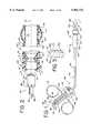
- FIG. 1shows a side view of a first embodiment of a urethral apparatus and an insertion tool showing the insertion tool partially cutaway.
- FIG. 2is a side sectional view of a distal portion and sensing component of the urethral apparatus of FIG. 1 and a partially cutaway view of a proximal portion of the insertion tool, uncoupled from the urethral apparatus.
- FIG. 3is an end view of the insertion tool of FIG. 2 taken from line 3-3'.
- FIG. 4Ais a side view of the deformable coupling of FIG. 3 in a released position.
- FIG. 4Bis an end view of the deformable coupling of FIG. 4A.
- FIG. 4Cis a side view of the deformable coupling of FIG. 4A in a locked position.
- FIG. 5Ais a side sectional view of the urethral apparatus of FIG. 1 and a partially cutaway view of a proximal portion of the insertion tool, coupled to the urethral apparatus.
- FIG. 5Bis a sectional view of the urethral apparatus taken along line 5B-5B' of FIG. 5A.
- FIG. 5Cis a sectional view of the urethral apparatus taken along line 5C-5C' of FIG. 5A.
- FIG. 6Ais an end view of the apparatus first contact collar of FIG. 5A.
- FIG. 6Bis a sectional side view of the apparatus first contact collar of FIG. 5A.
- FIG. 7is a side view of the proximal segment of the coupled urethral apparatus and insertion tool of FIG. 1 in one stage of being positioned in a urethra.
- FIG. 8is a close-up view of a distal end of the sensing component of the urethral apparatus during the stage of positioning shown in FIG. 7.
- FIG. 9is a side view of the coupled urethral apparatus and insertion tool of FIG. 7 in another stage of being positioned in the urethra.
- FIG. 10is a close-up view of a distal end of the sensing component of the urethral apparatus during the stage of positioning shown in FIG. 9.
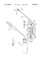
- FIG. 11is a side view of the urethral apparatus of FIG. 1 coupled to an alternate embodiment of an insertion tool.
- FIG. 12is a side view partially in section of the insertion tool of FIG. 11.
- FIG. 13is an exploded view of components of the insertion tool shown in FIG. 12.
- FIG. 14is a side view of the removable cover with the stop component of the insertion tool shown in FIGS. 11-13.
- FIG. 15is a side sectional view of the urethral apparatus of FIG. 1 and a partially cutaway view of a proximal portion of the insertion tool of FIGS. 11-14, coupled to the urethral apparatus.
- FIG. 16Ais a schematic flow diagram illustrating the electrical flow during coupling of the insertion tool and urethral apparatus of FIG. 15.
- FIG. 16Bis a schematic flow diagram illustrating the electrical flow during positioning of the insertion tool and urethral apparatus of FIG. 15.
- FIG. 17is a sectional view of another embodiment of a urethral apparatus having a preformed portion.
- FIG. 18is a sectional view of still another embodiment of a urethral apparatus, utilizing a piezoelectric transducer or membrane switch.
- FIG. 19Ais a schematic flow diagram illustrating the electrical flow during coupling of the insertion tool and urethral apparatus of FIG. 18.
- FIG. 19Bis a schematic flow diagram illustrating the electrical flow during positioning of the insertion tool and urethral apparatus of FIG. 18.
- FIG. 20is a sectional view of an alternate embodiment of a urethral apparatus, utilizing acoustic sensing.
- FIG. 21Ais a schematic flow diagram illustrating the electrical flow during coupling of the insertion tool and urethral apparatus of FIG. 20.
- FIG. 21Bis a schematic flow diagram illustrating the electrical flow during positioning of the insertion tool and urethral apparatus of FIG. 20.
- FIG. 22Ais a side view of the proximal end of an embodiment of the insertion tool illustrating the contact collar assembly and its interface with the contact collar of the urethral apparatus.
- FIG. 22Bis an end view of the contact collar housing of FIG. 22A.
- FIG. 22Cis an end view of the contact collar of FIG. 22A.
- FIG. 22Dis an end view of the contact collar housing of the urethral apparatus of FIG. 22A.
- FIG. 23is a sectional view of another alternate embodiment of a urethral apparatus that utilizes acoustic sensing.
- FIG. 24is a sectional view of a first alternate embodiment of a urethral apparatus that utilizes fluid flow sensing.
- FIG. 25Ais a partially cutaway side view of an insertion tool to be used with the embodiment of FIG. 24.
- FIG. 25Bis a close-up view of the proximal portion of the insertion tool of FIG. 25A.
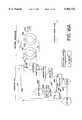
- FIG. 26Ais a schematic flow diagram illustrating the electrical flow during coupling of the insertion tool and urethral apparatus of FIG. 24.
- FIG. 26Bis a schematic flow diagram illustrating the electrical flow during positioning of the insertion tool and urethral apparatus of FIG. 24.
- FIG. 27is a sectional view of a second alternate embodiment of a urethral apparatus that utilizes fluid flow sensing.
- FIG. 28is a sectional view of a third alternate embodiment of a urethral apparatus that utilizes fluid flow sensing.
- FIG. 29Ais a cross-sectional view taken along line 29A-29A' of FIG. 28 showing the volume-deformable member in an expanded configuration.
- FIG. 29Bis the same cross-sectional view as shown in FIG. 29A showing the volume deformable member in a depressed configuration.
- FIG. 30Ais a sectional view of a fourth alternate embodiment of a urethral apparatus that utilizes fluid flow sensing shown in a closed mode.
- FIG. 30Bis a sectional view of the embodiment of the urethral apparatus shown in FIG. 30A shown in an open mode.
- FIG. 31is an expanded cross sectional view of the fluid passages shown in FIG. 30, taken along lines 31-31'.
- FIG. 32is a close-up sectional view of the proximal portion of the fluid passageways shown in FIGS. 30 and 31.
- FIG. 33Ais a partially cutaway side view of an insertion tool for use with the embodiment of the urethral apparatus in FIG. 32
- FIG. 33Bis a close-up view of the proximal portion of the insertion tool of FIG. 33A.
- FIG. 34is a sectional view of an alternate embodiment of a urethral apparatus that uses electrical resistance measurement for position sensing.
- FIG. 35Ais a schematic flow diagram illustrating the electrical flow during coupling of the insertion tool and urethral apparatus of FIG. 34.
- FIG. 35Bis a schematic flow diagram illustrating the electrical flow during positioning of the insertion tool and urethral apparatus of FIG. 34.
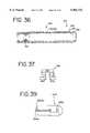
- FIG. 36is a sectional view of an alternate embodiment of a urethral apparatus that uses thermoelectric cooling to provide for position feedback
- FIG. 37is an expanded side view of the semiconductor used in the sensing component of FIG. 36.
- FIG. 38Ais a schematic flow diagram illustrating the electrical flow during coupling of the insertion tool and urethral apparatus of FIG. 36.
- FIG. 38Bis a schematic flow diagram illustrating the electrical flow during positioning of the insertion tool and urethral apparatus of FIG. 36.
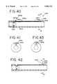
- FIG. 39is an expanded partial top view of an alternate embodiment of a urethral apparatus that uses fiber optics to provide for position feedback
- FIG. 40is a side view of the urethral apparatus of FIG. 39 at one stage of positioning, showing the fiber optic light being block or absorbed.
- FIG. 41is a cross-sectional view of the urethral apparatus of FIG. 40 taken along line 41-41'.
- FIG. 42is a view similar to FIG. 40 showing the urethral apparatus at another stage of positioning and showing the fiber optic light being reflected.
- FIG. 43is a cross-sectional view of the urethral apparatus of FIG. 42 taken along line 43-43'.
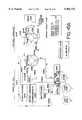
- FIG. 44Ais a schematic flow diagram illustrating the electrical flow during coupling of the insertion tool and urethral apparatus of FIG. 39.
- FIG. 44Bis a schematic flow diagram illustrating the electrical flow during positioning of the insertion tool and urethral apparatus of FIG. 39.
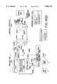
- FIG. 45Ais a schematic flow diagram illustrating the electrical flow during coupling of the insertion tool and an alternative embodiment of a urethral apparatus that uses only one fiber optic strand and an optical transducer.
- FIG. 45Bis a schematic flow diagram illustrating the electrical flow during positioning of the insertion tool and urethral apparatus of FIG. 45A.
- FIG. 46Ais a sectional view of an alternate embodiment of a urethral apparatus that incorporates drug delivery.
- FIG. 46Bis sectional view of an alternate embodiment of the urethral apparatus shown in FIG. 46A with a flow-restrictor valve.
- FIG. 47is a sectional view of another alternate embodiment of a urethral apparatus that incorporates drug delivery.
- FIG. 48is a sectional view of an alternate embodiment of a urethral apparatus that incorporates internal valving for fluid flow control and shown in a first, closed stage of operation.
- FIG. 49is a sectional view of the embodiment of FIG. 48 showing the valving components in a second, damping stage of operation.
- FIG. 50is a sectional view of the embodiment of FIG. 48 showing the valving components in a third, open stage of operation.
- FIG. 51is a sectional view of the embodiment of FIG. 48 showing the fluid flow path.
- FIG. 52is a side view of the fluid flow director of FIG. 48.
- FIG. 53is an end view of the fluid flow director of FIG. 48.
- FIG. 54Ais an end view of an embodiment of the magnet of FIG. 48.
- FIG. 54Bis an end view of an alternative embodiment of the magnet of FIG. 54A.
- FIG. 55is a sectional view of an alternate embodiment of a urethral apparatus that includes anchoring features for securing the apparatus in the urethra.
- FIG. 56is a sectional view of an alternate embodiment of a urethral apparatus having anchoring features.
- FIG. 57is a sectional view of the embodiment of FIG. 55 positioned within the urethra with lines illustrating forces applied to the apparatus.
- FIGS. 58A, 58B, and 58Cshow alternative embodiments for females of urethral apparatuses having anchoring structures.
- FIGS. 59A, 59B, 59C, 59D, and 59Eshow alternative embodiments for males of urethral apparatuses having anchoring structures.
- inventions for urethral placementprovide functions that require proper placement of the apparatus in the urethra.
- a proximal part of the apparatusbe in or close to the bladder so that urine can flow into an opening in the proximal end of the apparatus.
- These embodiments described belowinclude a feature that facilitates proper placement of the apparatus.
- FIGS. 1-10show a first embodiment of an apparatus 100.
- the apparatus 100is intended to be positioned in a urethra (shown in FIGS. 7-10) and to extend partially into a bladder (shown in FIGS. 7 and 9) of a patient.
- the patientmay be either a male or female human, or alternatively, embodiments of the apparatus may be used in other mammals or even in non-mammals, with suitable changes in dimensions.
- the apparatus 100includes a body 101 having a wall 102 with an exterior surface 103.
- the body 101has a generally tubular shape around axis 111.
- the body 101has a distal portion 105 terminating in a distal end 106 and a proximal portion 107 terminating in a proximal end 108.
- proximalrefers to the end which is at or close to the bladder and the term “distal” refers to the end opposite the proximal end and farther away from the bladder when the apparatus is in place.
- the proximal endwould be inserted first. This terminology convention applies as well to the insertion tool, described below.
- the cross sectional shape of the body 101may be generally circular or may be flattened to conform to the anatomical shape of the urethra.
- the body 101has a generally tubular shape around an axis 111.
- the proximal portion 107 of the body 101has at least one port 109 which may be located at the proximal portion 107 or proximal end 108 to allow for urine flow into and through the apparatus.
- the proximal end 108may have an open through-lumen to allow the apparatus to be used as an introducer for fluids, stents, or other apparatuses or to function as a temporary stent itself for diagnostic and therapeutic procedures in the lower or upper urinary tract.
- the body 101defines a passageway or lumen 101 that extends through the length of the body 101 from the proximal port 109 to a distal opening 115.
- the apparatus 100is produced using a composite construction of a base tube and cast external features.
- a base tubeis constructed as a braid reinforced silicone tube using a stainless steel wire braid and Shore A 60 durometer silicone compound as the tube polymer (tubing produced by New England Electric Wire Corp. Portugal, N.H.).
- the internal diameter of the base tubeis 0.160 inches using a braid core diameter of 0.180 inches.
- the external diameter of the base tubeis 0.210 inches.
- the body 101has an overall length such that the body 101 resides entirely within the urinary tract of the patient, preferably primarily within the urethra, except to the extent to which the proximal end 108 extends partially or completely into either the bladder or the bladder neck.
- the distal end 106 of the body 101 of the apparatus 100does not extend outside the urethra after it is positioned.
- additional elements or capabilitiesmay be provided, such as a fluid valving or drug delivery, as described more fully below.
- the body 101is less than 10 cm in length in versions for adult-sized male users and 5 cm in length for adult-sized female users, but more preferably less than 5 cm in length for female users.
- alternate embodiments of the apparatus 100can be employed in which the overall length of the body 101 is greater than the above dimensions.
- the distal end 106 of the body 101extends outside the urethra while the proximal end 108 is positioned within the bladder or the bladder neck.
- the distal end 106can be connected to a fluid collection or introducer system.
- the body 101may be sized from about 10 French to 34 French to accommodate the large range of urethral sizes from infants to adults.
- the exterior surface 103 of the body 101is constructed of molded silicone or alternatively of latex.
- Alternative materialsinclude molded polyurethane, polyethylene, polycarbonate, or other biocompatible materials.
- the urethral apparatus 100is releasably coupled with an insertion tool 150 for placement and removal.
- the insertion tool 150provides three functions. First, the insertion tool 150 couples to the urethral apparatus 100 and aids insertion of the apparatus 100 into the urethra, bladder neck, or bladder. Second, the insertion tool 150 completes the respective electrical circuits to provide feedback that the urethral apparatus 100 is coupled with the insertion tool 150. Third, the insertion tool 150 interfaces with the urethral apparatus 100 and completes the various electrical, optical, fluid, or mechanical circuits, channels, or linkages of the urethral apparatus 100 to provide feedback to the caregiver that the urethral apparatus 100 is properly positioned in relation to the bladder neck or bladder. These functions of the insertion tool 150 are described below.
- the insertion tool 150has a handle 151 and a linkage 152 that passes through a shaft 154.
- the linkage 152is connected to an actuating mechanism, such as a plunger 156, at a distal end 158 of the insertion tool and is connected to a deformable coupling 160 at a proximal end 162 of the insertion tool 150.
- the locking mechanismcan be a bayonet-type mechanism, which engages the alternate locking mechanism to maintain the plunger in a depressed position.
- the deformable coupling 160fits into an inner recess 113 in an entrance channel 114 in the distal portion 105 of the body 101 of the urethral apparatus 100, thereby locking the insertion tool 150 with the apparatus 100.
- FIG. 2shows the insertion tool 150 uncoupled from the apparatus 100 with the deformable coupling 160 at the proximal end 162 of the insertion tool 150 in an uncompressed mode
- FIG. 5Ashows the insertion tool 150 coupled to the urethral apparatus 100 with the deformable coupling 160 in a compressed mode.
- the urethral apparatus 100includes a sensing component 112.
- the sensing component 112is associated with the body 101, and in particular, the sensing component 112 is located along the axial length of the body 101.
- the sensing component 112senses a change in the environment of the urethra or a change in a feature of the urethra as the apparatus is being positioned in the urethra.
- the sensing component 112may respond to changes in anatomical features of the urethra as a portion of the apparatus 100 moves along the urethra and enters the bladder neck and bladder.
- the sensing component 112does not necessarily measure any particular condition or feature but instead detects a change in a condition, parameter, or feature.
- the sensing component 112may detect a change from a compressed state to an uncompressed state or to a less-compressed state, from an environment where outward force is registered to an environment where the same force is either no longer registered or is contained with less resistance, or from having one light or sound reflection quality or parameter to an environment having a different reflection quality (e.g., the urethra versus the bladder neck or the bladder).
- the sensing component 112can be a tactile sensor, a pre-loaded spring, a force-sensitive contact, a photo cell interacting with a fiber optic strand by radiating and receiving reflected light, a pair of fiber optic strands, a piezoelectric transducer or a membrane switch, a pneumatic or hydraulic electrical or mechanical indicator, a strain gauge, an acoustical-reflection sensor, a thermal couple, a thermistor, or a fluid-introduction port or fluid circuit in combination with a movable element actuating electrical or mechanical components.
- the sensing component 112includes appropriate scaling so that it can provide a positive indication when the apparatus is properly positioned relative to the features of the urethral environment.
- the sensitivity of the sensing componentis established so that it outputs a signal (preferably a single signal) indicating proper placement of the tubular body relative to the bladder neck and bladder. In this manner the sensing component distinguishes the change in the sensed feature from the urethral background environment to provide a signal indicating that the bladder neck or bladder have been reached.
- sensing component 112is described in conjunction with FIGS. 5A through 5C.
- This embodiment of the sensing componentis a mechanical-type sensor or pressure sensor.
- This embodiment of the sensing component 112is responsive to compressive forces applied to a portion of the body 101 of the urethral apparatus 100.
- the sensing component 112comprises a first wall 123 and a second wall 124.
- the first and second wallsare formed of tubular parts of the body 101 of the urethral apparatus 100 close to the proximal end 108.
- the first wall 123has shape-memory characteristics and assumes at least first and second positions (compare, for example, FIGS. 7 and 8 with FIGS. 9 and 10).
- the first wall 123is resilient and flexible.
- the first wall 123is formed so that it bows outward, as shown in FIG. 5A, in its at-rest condition. In this bowed condition, the first wall 123 is spaced away form the second wall 124, as shown in FIG. 5A.
- the first wall 123when compressive forces are applied to the first wall 123, it deflects to the flattened condition shown in FIG. 7. Movement from the bowed-out condition to the flattened condition causes a corresponding movement of axial length of the first wall 123. Because the proximal end 125 of the first wall is fixed, the distal end 126 of the first wall 123 is caused to move proximally or distally as a result of the bowing out or flattening of the first wall 123.
- lead wires 117 and 118interconnect conducting surfaces 116a and 116b of the apparatus first contact collar 116 to conducting surfaces 120a and 120b, respectively, of an apparatus second contact collar 120.
- the apparatus conducting surfaces 120a and 120bare separated by apparatus non-conducting surfaces 120c and 120d.
- the distal end 126 of the first wall 123has an apparatus third contact component 122 which has a continuous metalized conducting surface 122a. Completion of an electrical circuit between the apparatus second contact collar 120 and the apparatus third contact component 122 provides a feedback signal to the person positioning the apparatus, such as the caregiver, that the urethral apparatus is in the urethra.
- opening the electrical circuit between the apparatus second contact collar 120 and the apparatus third contact component 122provides a feedback signal that the urethral apparatus is properly positioned in the bladder neck or bladder (explained in more detail below). This allows the circuit between the apparatus second contact collar 120 and the apparatus third contact component 122 to be alternately opened or closed, depending on the position of the urethral apparatus 100 along the urinary tract.
- FIGS. 6A and 6Bshow the apparatus first contact collar 116 in more detail and show conductive surfaces 116a and 116b separated by nonconductive surfaces 116c and 116d.
- the apparatus first contact collar 116can be replaced with a contact film having conducting areas corresponding to the conductive surfaces 116a and 116b and non-conducting areas corresponding to the surfaces 116c and 116d.
- the sensing component 112 in the urethral apparatus 100works in conjunction with the insertion tool 150.
- the proximal end 162 of the insertion tool 150includes an atraumatic proximal tip 172 and an insertion tool contact collar 170.
- the tool contact collar 170is composed of three conductive areas 170a, 170b, and 170c.
- the contact collar 170has an oval cross-sectional shape.
- the insertion tool 150includes an indicator unit 164 (FIG. 1).
- the indicator unit 164uses any of various visual, audible, or other signaling indicators (e.g., a first light 165, a second light 166, and an alarm 167) that (1) receive electrical feedback that the urethral apparatus 100 and the insertion tool 150 are coupled and (2) receive feedback from the sensing component 112 that the apparatus 100 is properly positioned. This information is relayed along the tool shaft 154 through a lead bundle 168, for example, to the indicator unit 164 where it is observable by the caregiver or the patient.
- the indicator unit in the insertion tool 150is powered by a battery (not shown).
- the indicator unitmay be located at the distal end of the urethral apparatus. Such embodiments may be used in conjunction with an insertion tool that is used to facilitate positioning or may be used without insertion tools. In embodiments of the urethral apparatus in which the distal portion of the body of the urethral apparatus extends outside of the urethra during use, the indicator unit may be incorporated into the distal portion and may include appropriate audible, visual, or other signaling to indicate that the apparatus is properly positioned.
- the deformable coupling 160 of the insertion tool 150has a first diameter 174 and a first width 175 (as shown in FIGS. 4A and 4B) and is able to pass through the tapered distal end 106 of the tubular body 101.
- the proximal end 162 of the insertion tool 150is inserted into the entrance channel 114 and into the inner recess 113, which has a greater vertical cross-sectional area.
- the deformable coupling 160is compressed by an actuating linkage 152 using the plunger 156.
- the vertical diameter of the coupling 160is extended to a second, larger diameter 176 and a second width 177 (FIG.
- a biasing force applied to the plunger 156 (and thereby to the linkage 152) by the spring 178helps to maintain the deformable coupling 160 in a locked or coupled mode, and the stop 179 aids to limit travel of the plunger 156 thereby controlling the diameter of the deformable coupling 160.
- a locking mechanismcan be provided, such as a simple screw 180 and nut 181 combination, to secure the plunger shaft 182 in an uncompressed mode.
- FIGS. 7 and 8show the coupled insertion tool 150 and urethral apparatus 100 being inserted into the urethra 40.
- the urethral apparatus 100is passing through the urethra 40 and approaching the bladder neck 42.
- the sensing component 112is responsive to an environment that is relatively consistent within the urethra 40.
- the sensing component 112is in a flattened configuration, and the apparatus second contact collar 120 is in contact with the apparatus third contact component 122, which is part of the sensing component 112.
- This circuit between the apparatus second contact collar 120 and the apparatus third contact component 122is maintained while the proximal end 108 of the urethral apparatus 100 is still within the urethra 40.
- the sensing component 112is deformed due to the compressive forces exerted by the continuous surface of the urethra 40.
- the sensing component 112undergoes a change in shape.
- This changecauses the apparatus third contact component 122 to move away from the apparatus second contact collar 120, opening that circuit and thereby sending a feedback signal to the person positioning the urethral apparatus, such as the caregiver, that the urethral apparatus 100 is in proper position in relation to the bladder neck 42.
- the insertion tool 150can now be uncoupled from the urethral apparatus 100.
- FIG. 9shows the insertion tool 150 uncoupled from the urethral apparatus 100, leaving the urethral apparatus 100 in proper position in relation to the bladder neck 42 and bladder 44.
- the proximal end 162 of the insertion tool 150may have a tapered transition 184 from the shaft 154 to the deformable coupling 160 to ease withdrawal of the insertion tool 150.
- Removal of the urethral apparatus 100is accomplished using the above steps in reverse order.
- the linkage 152 of the insertion tool 150is actuated by the plunger 156 and locked to maintain the deformable coupling 160 in the first diameter 174 and the first width 175.
- the insertion tool 150is inserted into the urethra until it engages the distal end 106 of the urethral apparatus 100.
- the proximal end 162 of the insertion tool 150is further inserted into the entrance channel 114 of the distal end 106 of the urethral apparatus 100 until the tool contact collar 170 of the insertion tool 150 engages the apparatus first contact collar 116. This engagement can be confirmed by observing actuation of the first light 165.
- the deformable coupling 160is then changed to the second, larger diameter 176 and the second width 177 by releasing the plunger 156 thereby locking the insertion tool 150 to the urethral apparatus 100. Once coupled, removal of the tool and urethral apparatus can proceed by pulling on the distal end of the tool.
- the coupled or joined urethral apparatus 100 and insertion tool 150can be inserted in the urethra with the aid of an insertion sleeve (not shown), which is inserted in the urethra 40 either prior to or simultaneously with the joined urethral apparatus and tool.
- the insertion sleevecan be a short or a long sleeve, or an everting sleeve that may aid in reducing the introduction of bacteria higher into the urethra or bladder.
- the sleevehas a length such that it does not interfere with the sensing component 112 on the body of the urethral apparatus.
- the sleevemay also have a longitudinal line of weakness to facilitate removal of the sleeve, for example by tearing.
- a coating on the sleevepreferably including lubricating and antibacterial substances, may be used to aid in insertion within the urinary tract.
- FIGS. 11 through 15show an alternative embodiment 250 of the insertion tool, which can be used for placement of the urethral apparatus 100.
- the insertion tool 250provides for an axial orientation of the caregiver's hand during insertion and removal.
- the plunger and locking mechanismare integrated within a handpiece housing 251.
- a proximal end 262 of the insertion tool 250has an atraumatic distal tip 272, which is interconnected with a cable or other linkage 252 that passes through a shaft 254 of the insertion tool 250.
- the linkage 252is connected to a plunger 256 and has a biasing spring 278 (best shown in FIG. 12).
- a sleeve 257serves to center the spring 278 over the linkage 252 (FIG. 13).
- a battery 259which supplies power for the insertion tool 250, is inserted through a distal end 258 of the insertion tool 250 and is held in place with a nut 281 and a battery spring 261.
- a ground contact strip 263 for the battery 259is located adjacent to and in contact with the battery spring 261 and with a ground lead 269.
- a positive contact 283 for the battery 259is connected to a positive lead 284 and is connected to the circuitry in an indicator unit 264.
- FIG. 12also shows a lead bundle 268 consisting of individual leads 268a, 268b, and 268c (best shown in FIG. 15) that carry feedback signals indicating proper coupling and positioning.
- the individual leadsterminate within the indicator unit 264 which is further detailed in the circuit flow diagrams and descriptions discussed below.
- the indicator unit 264is joined to the shaft 254 of the insertion tool 250 with a slip connector 255.
- the slip connector 255allows the distal end 258 to be rotated to aid in coupling the insertion tool 250 with the urethral apparatus 100 and to aid insertion of the coupled tool and urethral apparatus through the urethra.
- the insertion tool 250has an insertion tool contact collar 270 close to its proximal end 262.
- the contact collar 270includes three conducting surfaces 270a, 270b and 270c (FIG. 16B), which interface with the conducting surfaces 116a and 116b of the first contact collar 116 of the urethral apparatus 100 to complete a circuit that indicates proper coupling of the insertion tool 250 with the urethral apparatus 100.
- the conductive surfaces 270a, 270b, and 270care connected to the three electrical leads, 268a, 268b, and 268c, respectively. These leads are located within the shaft 254 of the insertion tool 250 and terminate within the indicator unit 264 at electrical contacts that communicate with a first light 265, a second light 266, and an alarm 267.
- FIGS. 16A and 16BThe electrical circuit flows during coupling and insertion are diagrammed in FIGS. 16A and 16B.
- the circuit flow during couplingis shown in FIG. 16A.
- the battery 259is connected to a switch 285 at a first contact 286 by the positive lead 284.
- a second contact 287 and the conductive surface 270bare interconnected by the lead 268b.
- an electrical connection between the insertion tool conductive surfaces 270b and 270cis made when each comes in electrical contact with the conductive surface 116a of the urethral apparatus 100.
- the first light 265is activated.
- the switch 285Also receiving power through the switch 285 is an inverter 294 and a relay 295, which receive power through a third switch contact 288 and a lead 268d.
- the switch 285can be in one of two positions for receiving feedback. The first position is used during coupling, and the second position is used during positioning.
- FIG. 16Billustrates the circuit flow during insertion and positioning.
- the sensing component 112is compressed against the outer surface of the body 101 such that the conductive surface 122a of the third contact component 122 electrically interconnects the second conducting surfaces 120a and 120b of the second contact collar 120.
- the leads 117 and 118electrically interconnect the first contact collar 116 with the second contact collar 120.
- Both the first and second lights 265 and 266are on unless the switch 285 is in the off position.
- the inverter 294translates the electrical signal returning through the lead 268a to indicate when the sensing component 112 becomes uncompressed, i.e.
- the third contact component 122 located on the sensing component 112becomes electrically disconnected from the conducting surfaces 120a and 120b when the urethral apparatus 100 enters the bladder, and an electrical signal is transferred through the lead 268e to the switch 285 to activate the second light 266 and/or alarm 267.
- the second light 266 and the alarm 267may be selectively activated depending on the user's setting of the switch 285.
- the switch 285has four positions. In a first position, the electrical circuitry is off. In a second position (for coupling), the first light 265 is activated when the circuits are completed between the insertion tool contact collar 270 and the first contact collar 116 of the urethral apparatus 100. When the switch 285 is in a third position (for positioning or insertion), the input contact 289 and the light contact 290 are interconnected and the second light 266 activates indicating entrance to a body passageway with increased area (e.g., diameter).
- a body passagewaywith increased area (e.g., diameter).
- the input contact 289is interconnected to the light/alarm contact 291 and the second light 266 and the alarm 267 are activated, thereby indicating entrance to a body passageway of increased area (i.e. diameter).
- the input contact 289is activated either directly via the voltage source, or with an optional relay 295.
- the inverter 294reverses the activation of the second light 266 (or the alarm 267) relative to the operation described in connection with the first embodiment of the insertion tool. Instead of being turned off when a current path between the apparatus conducting surfaces 120a and 120b and the apparatus component surface 122a is interrupted, the inverter 294 causes the second light 266 (or the alarm 267) to be turned on when the current path is interrupted. Thus, the inverter 294 is provided to effect this alternative mode of operation. Accordingly, it is understood that the use of the inverter is optional depending upon the mode desired.
- FIG. 17shows another embodiment 100A of the urethral apparatus.
- the urethral apparatus 100Aincludes a tubular body 101A having a proximal portion 107A terminating in a proximal end 108A.
- a sensing component 112Ais comprised of a preformed, shape-memory portion incorporating internal electrical switching.
- the proximal portion 107Aincludes a preformed portion 131 A.
- the preformed portion 131Ais flexible and resilient and has an other-than-straight shape when at rest.
- a slidable contact 132Ais fixed distally at a position 134A and displaced relative to a proximal contact pair 135A as deformation of the preformed portion 131A occurs upon entry into the bladder neck or bladder.
- the apparatus proximal contact pair 135Acan open, thus opening an electrical circuit through the apparatus conductive leads 117A and 118A, which interconnect the proximal contact pair 135A and the apparatus first contact collar 116A, which is in contact with the insertion tool 150 (or 250), thereby activating a signal on the indicator unit 164 (or 264) thereof
- the apparatus proximal contact pair 135Acan be located in a more distal position near the apparatus first contact collar 116A.
- the preformed portion 131Ais incorporated within or utilized with an anchoring mechanism, which provides for an electrical feedback to give an indication of entry into the bladder neck or bladder and to confirm proper positioning in relation to the bladder neck or bladder.
- FIGS. 18, 19A, and 19Bshow another alternate embodiment of a urethral apparatus 100B.
- a sensing component 112Bcomprises conductive contact terminals that form a switch that can sense entry into a bladder neck or bladder.
- a proximal portion 107B of a body 101B of the urethral apparatus 100Bincludes a switch 127B that displaces an internal contact pair 128B (shown in the circuit flow diagram of FIGS. 19A and 19B) as the proximal portion 107B of the urethral apparatus 100B containing the switch 127B enters the bladder neck or bladder.
- This displacementcauses the contact pair 128B to open, thus opening the electrical circuit through the conductive leads 117B and 118B, which interconnect the switch 127B and a first contact collar 116B, which is in contact with the insertion tool 150 (or 250), thereby activating a signal on the indicator unit 164 (or 264) thereof
- the sensing componentcan be designed to sense changes in light, pressure, force, vibration, compression, heat, or other sensed conditions. These alternative embodiments are described below.
- FIGS. 20, 21A, and 21Bthere is shown an embodiment of a urethral apparatus 200 that utilizes a acoustic sensing component 212 to generate an indication of proper placement.
- the embodiment of FIGS. 20, 21A, and 21Bfunctions similarly to the embodiment in FIG. 18 except that the switch 127B of FIG. 18 is replaced with an acoustical transducer 227.
- the acoustical transducer 227is preferably a piezoelectric acoustical transducer, but alternatively, may be a magnestrictive acoustical transducer.
- the acoustic transducer 227is preferably located within the body 201 of the urethral apparatus 200. The acoustic transducer 227 is activated to generate a pulsed mode signal and receive an acoustical signal.
- FIG. 21Bshows the electrical current flow path during positioning of the embodiment of the urethral apparatus 200 shown in FIG. 20 operating in a pulsed echo mode.
- Currentflows from a third contact 288 of a switch 285 through a lead 268d to a voltage conditioner 280.
- the voltage conditioner 280(which may optionally be a component of the pulse generator/time delay 282) provides for the necessary preamplification.
- the pulse generator/time delay 282provides for the formation of the excitation impulse wave form used to resonate the acoustical transducer 227.
- the impulse wave formis transmitted through a lead 268f to a conducting surface 270b of the insertion tool contact collar 270 and then to the conductive surface 216a of the first contact collar 216 of the urethral apparatus 200.
- the wave formis then transmitted through the lead 217 to the acoustical transducer 227.
- the acoustical transducer 227is resonated at the characteristic frequency of the transducer which may range from as low as approximately 1 Kilohertz to as much as approximately 100 Megahertz. In one embodiment, a range of resonate frequencies within two orders of magnitude of 1 Megahertz is appropriate.
- the resonate frequency of the transduceris dependent on its material properties and thickness.
- the pulse generator wave formis a triangular or square wave with amplitudes ranging up to approximately 100 volts.
- the pulse generator/time delay 282provides for an excitation voltage followed by a wait state prior to re-initiation of the next resonance.
- the resonance of the transducer 227provides for an energy transmission into the adjacent materials; this transmission is in the form of an acoustical beam as the energy is transmitted through the adjacent material at the speed of sound of the material itself.
- the surrounding materialseither reflect, absorb, or transmit the energy.
- the energy that is reflectedprovides an indication of the surrounding environment.
- the initial reflections which impact the acoustical transducer surface 204 following the completion of the resonance from the initial excitationre-resonate the transducer 227.
- This resonanceproduces an electrical potential (voltage) at the surfaces which is conducted back through leads 217 and 218 to the conductive surfaces 216a and 216b of the first contact collar 216, through the conductive surfaces 270a and 270b of the insertion tool contact collar 270, and to the pulse generator/time delay 282 through leads 268a and 268f.
- the voltage differential between the leads 268a and 268fdiminishes substantially during the pulsed echo cycle when the acoustical transducer 227 enters the regions of increased area in the bladder neck and bladder. Because the distance from the acoustical transducer surface 204 to the body tissue surface increases at the bladder neck and bladder, there is a substantial reduction in the reflected energies compared to the more intimate contact within the tighter areas of the body such as the urethra.
- the voltage threshold comparator and a relay 299register the peak reflected voltage.
- an input contact 289is activated either directly via the voltage source, or with an optional secondary relay (not shown).
- the switch 285is in a position in which the input contact 289 and the light contact 290 are interconnected, the second light 266 lights indicating entrance to a body cavity with increased area.
- both the second light 266 and the alarm 267are activated.
- a voltageis generated and transmitted to the insertion tool 250 external to the patient's body where the wave form is processed using the analog or digital circuitry contained within insertion tool 250.
- the distance away from the transducer to the surface of the urethra, bladder neck, or bladderis determined by the elapsed time from the completion of a generated signal until the first wave return.
- the distance from the transducer to the surface of the urethra, bladder neck, or bladderis determined by the change in intensity of the reflected acoustical waves. In either case, a change in state becomes apparent by the acoustical reflections as the apparatus 200 enters the or bladder.
- the insertion tool 250then generates an appropriate audible, visual, analog, or other signal of this change.
- sensing componentuses other methods of initiating feedback to the caregiver that the urethral apparatus is properly positioned.
- other embodimentsare the use of one- and two-way fluid flows, fiber optics, electrical resistance, thermoelectric semiconductors, and two-transducer acoustic mechanisms.
- These embodimentsuse an alternate embodiment of the insertion tool electrical contact collar.
- an alternate embodiment of an insertion tool contact collar 270A for use with the urethral apparatus first contact collarallows for additional convenience when coupling.
- Both contact collarsinclude conducting surfaces and non-conducting surfaces that form circuits to indicate either coupling of the insertion tool with the urethral apparatus or proper positioning within the bladder neck or bladder.
- both contact collarsare oval-shaped and have additional mating contact points to accommodate various fluid-flow pathways and fiber optics connections. For convenience, there are twice as many of these additional mating contact points on the insertion tool contact collar 270A as there are mating contact points on the urethral apparatus first contact collar (116 or 216) so that either of the two 180-degree orientations are functional.
- FIG. 22Ashows the proximal portion of the insertion tool 250 and further illustrates the assembly of the contact collar 270A to the contact collar housing 270.5. Also shown in the figure is the contact collar 116 (or 216) of the urethral apparatus 100 (or 200) to illustrate how the contact collars of the insertion tool 250A and the urethral apparatus 100 (or 200 and following embodiments) interface with one another.
- the table belowshows the number and type of the contact points or mating contact points provided on the insertion tool contact collar 270A, the urethral apparatus first contact collar 116 (or 216), and the number of leads for the various embodiments in this disclosure. As mentioned above, the number of contact points or ports on the insertion tool contact collar 270 may be doubled for convenience when coupling.
- FIG. 23illustrates a second acoustic embodiment (apparatus 200A).
- a sensing component that uses acoustic sensingin shown generally at 212A.
- This embodimentutilizes two magnestrictive, or preferably, piezoelectric acoustical transducers 227A(1) and 227A(2) on an exterior surface 203A of the urethral apparatus 200A. These transducers 227A(1) and 227A(2) are activated to respectively generate and receive a continuous mode acoustical signal.
- This embodimentis similar to the first acoustic embodiment except that in this embodiment, a first transducer 227A(1) generates a continuous mode acoustic signal rather than a pulsed signal, while a second transducer 227A(2) receives the signal.
- Electrical leads 217Aa, 217Ab, 218Aa, and 218Abcarry an electrical potential (voltage) to and from the transducers 227A(1) and 227A(2), respectively, and are interfaced with electrical leads 268 in the insertion tool 250 through the contact collars 270 and 216A to provide for a feedback signal.
- Circuitry in the insertion toolis similar to that shown for the first acoustic embodiment (see FIG. 21A) except that the pulse generator is replaced by a continuous mode generator.
- the surrounding materialseither reflect, absorb, or transmit the energy.
- Acoustic energyis emitted by the first acoustical transducer 227A(1), reflected by the urethral wall, and received by the second transducer 227A(2), which resonates and produces an electrical potential (voltage) that provide an indication of the surrounding environment.
- This voltagediminishes substantially when the transducers enter the bladder neck and bladder where the distance from the transducer surfaces to the body tissue surface increases and causes a substantial reduction in the reflected energies compared to the more intimate contact within tighter areas of the body such as the urethra.
- the two transducersare placed facing each other, separated by a non-reflective, shape-memory member similar to that used in the fiber optic embodiments, described below.
- a change is acoustic signalis noted when the proximal end of the urethral apparatus carrying the transducers enters the bladder neck and bladder, thereby allowing the shape memory member to be displaced outward which, in turn, permits an unobstructed face-to-face orientation of the two transducers.
- Pressurized fluid flowmay be used to provide for position feedback to ascertain that the urethral apparatus is properly positioned.
- Four approaches using pressurized fluids in combination with an insertion tool and urethral apparatusare described below.
- the first three approachesprovide a one-way flow of fluid from an insertion tool, through the urethral apparatus, and into the urethra, bladder, or a fluid reservoir located in urethral apparatus. This flow can be restricted to varying degrees.
- fluid flowis restricted because of the urethra.
- the proximal portion of the urethral apparatusenters the bladder neck or bladder, the flow becomes less restricted.
- the fourth approachdoes not permit fluid to escape into the urethra and bladder, but incorporates a two-way flow of fluid from the insertion tool, through the urethral apparatus, and back to the insertion tool.
- a first fluid flow embodimentis shown in FIGS. 24, 25a, 25b, 26a and 26b.
- a urethral apparatus 300Aprovides for a limited passage of fluid into the urethra or bladder.
- the sensing componentis shown generally at 312A.
- fluidis allowed to pass from an insertion tool 350 and into a urethral apparatus 300A.
- the fluidis under pressure in a fluid reservoir 353 that is contained within the insertion tool 350. Pressure can be applied by a thumb screw and piston in combination with a biasing spring 353.5 located on the distal end of a handpiece housing 351.
- Fluidflows through a fluid passageway 373a, through a passageway port 374, against the a flexible conduit wall 375 which contacts a normally closed, pressure-responsive membrane switch 376, and through a fluid passageway 373b that extends through a shaft 354.
- the normally closed membrane switch 376When fluid is in stasis due to resistance or complete retention of fluid, the normally closed membrane switch 376 is electrically open. When the fluid pressure diminishes due to a dynamic fluid state, the flexible conduit wall collapses under the pressure of the normally closed membrane switch 376. The fluid then flows through a mating contact point 371 of an insertion tool contact collar 370 through a contact port 334A of the urethral apparatus 300A, through a passageway 311A, and out through a apparatus port 313A, which could be a porous or microporous membrane. The fluid is expelled into the urethra, the bladder neck, or the bladder, depending upon the location of the coupled insertion tool 350 and apparatus 300A.
- the change in restriction of flowis detected by the normally closed membrane switch 376.
- the membrane switch 376detects the lower system pressure. The pressure-responsive, normally closed membrane switch 376 then returns to the unengaged position and closes the internal contacts, thus completing a circuit between the contacts 377a and 377b, the energizing input contact 389, and the second light 366.
- the switch 385Depending on the position of the switch 385, either the light only, or the light and alarm, gives an indication that the proximal portion 307A of the urethral apparatus 300A has entered the bladder neck or bladder as previously described in the other embodiments.
- the input contact 389is activated either directly via the voltage source or with an optional secondary relay (not shown).
- FIG. 27there is shown a second embodiment 300B of a urethral apparatus that uses fluid-flow for sensing.
- the sensing componentis shown generally at 312B.
- This embodimentprovides for a limited passage of fluid into the bladder neck or the bladder when a proximal portion of the apparatus 300B containing a restricted apparatus port 313B enters the bladder neck or bladder.
- This configurationis similar to the first fluid-flow embodiment 300A except that no fluid is allowed to pass into the urethra during insertion due to the physical contact of the urethra on the flow restrictor valve 315B that thereby closes the apparatus port 313B.
- the system mechanics and electronicsfunction similarly to the first fluid-flow configuration.
- FIG. 28 through FIG. 29BA third embodiment of a urethral apparatus 300C using a fluid-flow configuration is shown in FIG. 28 through FIG. 29B.
- the sensing componentis shown generally at 312C.
- This embodimentprovides for fluid feedback without the introduction of fluid into either the urethra, bladder neck, or bladder by providing for a one-way fluid flow from the insertion tool 350 into a fluid reservoir 319C located in the urethral apparatus 300C.
- Adjacent to the fluid reservoir 319Cis a volume-deformable member 321C.
- the fluidis under pressure in the reservoir 353 contained within the insertion tool 350.
- This fluidflows through the fluid passageway 373a and 373b, through the shaft 354, then through the mating contact point 371 of the insertion tool contact collar 370, through a contact port 334C of the urethral apparatus 300C, through the apparatus passageway 311C and the port 313C, and into a fluid reservoir 319C
- the volume-deformable member 321Cis in a flattened profile, as shown in FIG. 29a.
- volume-deformable member 321CWhen the portion of the urethral 300C containing the volume-deformable member 321C enters the bladder neck or bladder, fluid pressure within the system causes the volume-deformable member 321C to deform to a second, larger profile as shown in FIG. 29b, thus lowering fluid pressure within the circuit.
- This change in fluid pressurecauses the pressure-responsive, normally closed membrane switch 376 to return to the undeflected position, thus completing a circuit between the contacts 377a and 377b and the energizing input contact 389 and the second light 366.
- the system electronicsfunction similarly to the first two fluid-flow configurations.
- FIG. 30A through FIG. 33BA fourth embodiment of a urethral apparatus 300D that uses fluid-flow sensing is shown in FIG. 30A through FIG. 33B.
- This embodimentalso provides for fluid-initiated feedback without the introduction of fluid into either the urethra, bladder neck, or bladder by providing for a two-way fluid flow from the insertion tool 350 through the urethral apparatus 300D and back to the insertion tool 350.
- the sensing componentis shown generally at 312D.
- the fluidwhich is under pressure in the first fluid reservoir 353a that is contained within the insertion tool 350, flows through the shaft 354 and into the urethral apparatus 300D.
- fluidis allowed to flow through an input passageway 311Da of the urethral apparatus 300D and return through a return passageway 311Db.
- the input passageway 311Da and the return passageway 311Dbare interconnected (as illustrated in FIG. 32) distal to a depressible contactor 329D, allowing for fluid flow in the fluid circuit when a depressible contactor 329D is open, but preventing fluid flow in the circuit when the depressible contactor 329D is depressed.
- the depressible contactor 329Dis located on the surface of the urethral apparatus 300D and is responsive to the physical contact of the urethra.
- the depressible contactor 329Dserves to restrict the flow of fluid within the fluid circuit by preventing the return flow while the insertion tool 350 and apparatus 300D are being inserted through the urethra.
- the depressible contactor 329DWhen the portion of apparatus 300D containing the depressible contactor 329D enters either the bladder neck or the bladder, the depressible contactor 329D is free to move outward, (FIG. 30B) thus allowing the fluid within the fluid circuit to return through the return passageway 311Db and collect in a second fluid reservoir 353b in the insertion tool 350.
- This change in fluid pressurecauses the pressure-responsive, normally closed membrane switch 376 to return to the unengaged position, thus completing a circuit between contacts 377a and 377b and energizing the input contact 389 and the light 366.
- the system electronicsfunction similarly to the first three fluid-flow configurations.
- the embodiment of the urethral apparatus 400that uses electrical resistance measurement for position sensing.
- the sensing componentis shown generally at 412.
- the electrical resistance between two spaced-apart locations along the urethrawill differ from the resistance across the same distance within an aqueous fluid such as urine.
- the embodiment of the urethral apparatus 400includes two, spaced electrical contacts (a first contact 428a and a second contact 428b positioned along the body 401 thereof. These electrical contacts allow for the passage of a minute current between them as apparatus 400 is installed.
- the urethraitself allows an electrical conduction as the apparatus 400 is fed through the urethra.
- the electrical contacts 428a and 428breach the or bladder, the electrical resistance between the contacts changes as the apparatus 400 enters a pool of urine in the bladder neck or bladder. This change may be detected electronically with relatively simple analog or digital circuitry and thus activate a feedback signal.
- FIGS. 35Ais a circuit flow diagram showing the current flows during coupling for this embodiment and aid to further explain the embodiment.
- FIG. 34Bis circuit flow diagram showing the current flows during positioning. The current flows from a battery 459, through a positive lead 484, to a switch 485 in the insertion tool 450, then through a lead 468b to a voltage conditioner 480, which provides the correct voltage. The current flows through an electrical lead 468f, through the contact collars 470 and 416, and through an electrical lead 417 in the urethral apparatus 400 to a first contact 428a on or near the surface 403 of the body 401 of the urethral apparatus.
- the currentis then conducted across the conductive media of the urethra or urine to a second contact 428b, through an electrical lead 418, through the contact collars 416 and 470, and back through the electrical lead 468a in the insertion tool 450 to a voltage threshold comparator and relay 499.
- a voltage threshold comparator and relay 499When the portion of apparatus 400 that contains the first contact 428a and second contact 428b enters the bladder neck or bladder and is situated in a pool of urine as described above, the change in electrical resistance is detected by the voltage threshold comparator and relay 499 due to the resultant change in voltage. The voltage threshold comparator and relay 499 then compares this voltage with the predetermined, preset voltage.
- the voltage threshold comparator and relay 499energizes the input contact 489 through the lead 468e with the line voltage from the battery 459.
- the switch 485either the light only, or the light and alarm gives an indication that the urethral apparatus 400 has entered the bladder neck or bladder as previously described in other embodiments.
- thermoelectric moduletypically is composed of one or more pairs (couples) of semiconductors of Bismuth Telluride that has been negatively or positively doped.
- the pairs of semiconductorare in a thermally parallel circuit and in an electrical serial circuit.
- thermoelectric heat transfereffectively performs the function of transferring heat from a donor surface to a receptacle surface.
- the rate of heat transferis determined by the semiconductor characteristics as well as the electrical power being transferred through the semiconductor pairs. Given a constant direct voltage, the current increases when more heat is being transferred, and the current decreases when less heat is being transferred between the surfaces.
- the Peltier-effect cooling methoduses the two junctions of a semiconductor 530 (FIG. 37) which are heat-transfer activity cells in a manner such that a first junction 531 is in contact with the fluid or tissue adjacent to it which transmits heat energy from the urethra to a second heat junction 532 within the body 501. This transmitted heat is quickly reabsorbed by the body 501 and surrounding tissue or fluid surrounding the body 501. Similar to the electrical resistance embodiment above, a voltage threshold comparator and relay 599 then compares this current with the predetermined, preset current.
- the semiconductor 530has a thin construction of an overall dimension of approximately 0.008 inch in thickness with width dimensions of 0.020 inch and 0.040 inch.
- a gold or platinum conductive layeris applied using vapor deposition.
- a 0.0008 conductive filmmay be adhered to the surface 503 of the body 501 using conductive epoxy adhesive.
- the foilassists in the transfer of heat and provides a noble and biocompatible surface for interface with the surrounding environment.
- the dimensions of semiconductor 530determine the ability to transfer heat from the lower temperature junction to the higher temperature junction.
- the useful determinate indicator of positionis derived from the change in power which is used to transfer the heat rather than a measurement of the heat transfer. The power changes as the surrounding environment changes when the first junction 531 of the semiconductor 530 enters the bladder neck or bladder from the urethra.
- FIGS. 38Ais a circuit flow diagram showing the current flows during coupling for this embodiment and aids to further explain the embodiment.
- FIG. 38Bis a circuit flow diagram shows the current flows during positioning.
- Low-voltage, direct currentflows from a battery 559 through a positive lead 584 to the switch 585 and then through a lead 568b and is conditioned by a voltage conditioner 580, which provides the desired voltage and current limits.
- the currentflows then through a lead 568Ab, through a contact collar 570 of the insertion tool 550 and a contact collar 516 of the apparatus 500, and through the electrical lead 517 to the semiconductor 530.
- the currentpasses through the semiconductor junctions 531 and 532 and is conducted back through the electrical lead 518, through the contact collars 516 and 570, and through the second electrical lead 568a in the insertion tool 550 to the voltage threshold comparator and relay 599.
- the change in environmentcauses the first junction 531 to absorb a different amount of heat, thereby causing a resultant change in current.
- the voltage threshold comparator and relay 599then compares this current with the predetermined, preset current. When the current value exceeds the preset level, the voltage threshold comparator and the relay 599 energizes the input contact 589 through the lead 568e with line voltage from the battery 559.
- either the light only, or the light and alarmgive an indication that the apparatus 500 has entered the bladder neck or bladder as previously described in other embodiments.
- FIGS. 39 through 45Bshow alternative embodiments of urethral apparatus 600A and 600B that use fiber optics for position sensing.
- the fiber opticsare incorporated into the urethral apparatus to initiate a feedback signal that the apparatus is properly positioned.
- the sensing componentare shown generally at 612A and 612B, respectively.
- the embodiment 600A shown in FIGS. 39 through 44Bincludes two fiber optic strands that provide for signal transmission and return.
- the fiber optic strandsare composed of a central core of diameter of approximately 8 to 10 micron with a total clad or unclad diameter of approximately 125 micron (or approximately 0.005 inch).
- a low-energy light wave preferably in the visible light spectrum wavelengths of 400-750 nanometersis transmitted by a bulb or light-emitting diode (LED) 696A or bulb into the first insertion tool fiber optic strand 697Aa to the insertion tool contact collar 670A and terminates there within the strand casing at a mating contact point 671Aa, which may be a similar glass fused contact mounted within the contact collar 670A or a dissimilar material that has been bonded around the perimeter, which in turn is bonded into the insertion tool contact collar 670A.
- LEDlight-emitting diode
- a first apparatus fiber optic strand 633Aaterminates in like manner at a mating contact point 634Aa of an apparatus first contact collar 616A and extends within the body 601A to a location at a proximal portion 607A.
- a second apparatus fiber optic strand 633Ablies alongside the first apparatus fiber optic strand 633Aa and is coupled in like manner at a mating contact point 634Ab of the apparatus first contact collar 616A. Facing the terminal ends of the first and second apparatus fiber optic strands 633Aa and 633Ab is a mirror 635A, which reflects light emitting from the first apparatus fiber optic strand 633Aa into the second apparatus fiber optic strand 633Ab.
- a second insertion tool fiber optic strand 697Ablies alongside the first insertion tool fiber optic strand 697Aa and terminates in a handpiece housing 651A and contact collar 670A at a mating contact point 671Ab.
- An additional feature of this embodimentis the use of a shape-memory, nonreflective member 636A (FIGS. 40 and 41) that is interposed between the terminal ends of the first and second apparatus fiber optic strands 633Aa and 633Ab and the mirror 635A during insertion of the coupled insertion tool 650A and urethral apparatus 600A, thus, effectively preventing light from being returned through the second apparatus fiber optic strand 633Ab.
- a shape-memory, nonreflective member 636AFIGS. 40 and 41
- the shape-memory characteristics of the nonreflective member 636Acause it to move outward and therefore allow the light circuit to be completed (FIGS. 42 and 43).
- the nonreflective member 636Aoptionally has an additional leaf 637A to ensure complete blockage of the light circuit between the terminal ends of the apparatus fiber optic strands 633Aa and 633Ab and the mirror 635A.
- deformationcan take place in response to internal pressure from self-contained fluid in a reservoir adjacent the nonreflective member 636A.
- the reflective and absorptive properties of the leaf 637A and the mirror 635Acould be reversed in such a manner that the light from the fiber optic strands is reflected by the leaf 637A and the mirror 635 is replaced by a nonreflective surface.
- the shape-memory characteristicscause the nonreflective member 636A to move outward and thereby allow the light circuit to be completed (see FIG. 44b).
- the lightis returned to the second insertion tool optic fiber strand 697Ab and is incident upon the optical transducer 698A, the light energy is converted into an electrical signal, which is carried by the lead 668Aa to a voltage threshold comparator and relay 699A.
- the voltage threshold comparator and relay 699Athen compares this voltage with the predetermined, preset voltage.
- the voltage threshold comparator and relay 699Aenergizes an input contact 689A through the lead 668Ae with line voltage from the battery 659A.
- the switch 685Aeither the light only, or the light and alarm give an indication that the apparatus 600A has entered the bladder neck or bladder as previously described in other embodiments.
- the urethral apparatus 600Bhas only one fiber optic strand 633Ba and has an optical transducer 638B located in the distal portion 605B of the body 601B with an electrical lead 618B leading from the optical transducer 638B to a conducting surface 616Bc.
- Currentthen flows to a contact 670Bd of the insertion tool 650B and to a voltage threshold comparator and relay 699B through the lead 668Bd.
- the voltage threshold comparator and relay 699Benergizes the input contact 689B through the lead 668Be with line voltage from the battery 659B.
- either the light only, or the light and alarmgive an indication that the urethral apparatus 600B has entered the bladder neck or bladder as previously described in other embodiments.
- the mirror 635A(or 635B) may be eliminated in either of the configurations shown in FIGS. 44A and 44B (or 45A and 45B) by orienting the two ends of the fiber optic strands 633Aa and 633Ab (or optionally, first fiber optic strand 633Ba and optical transducer 638B) at a spaced distance across from each other with the non-reflective shape-memory member 636A (or 636B) interposed between the two elements. Similar circuitry to that described above would be employed.
- position sensingcan be derived from the reflection of light from the urethral surface. Such reflection is dependent upon the incidence of the surface and the distance to the surface on which the light is imparted. It is not necessary to visualize details of the internal surface of the urethra in order to detect the position of the apparatus within the urethra. Instead, it is important to be able to macroscopically characterize the environment and identify when the environment changes from that of the urethral surface to the urine occupying the bladder neck or bladder.
- Fiber optics to derive position sensing from intraurethral reflectionis provided by incorporating one or more fiber optic strands in two locations along the body of the urethral apparatus or the insertion tool.
- a first strandilluminates the area to be evaluated.
- the second strandconducts a surface illumination from the illuminated surface to the insertion tool.
- a first strandilluminates the area to be evaluated, and a photovoltaic cell is used to receive the incidence light and generate an electric voltage that produces a current that is conducted to the indicator unit.
- This output voltagemay then be used to indicate the change in reflection that occurs as the apparatus enters the bladder neck or bladder. This change may be electronically detected, and the caregiver who is inserting the urethral apparatus is thereby alerted.
- the disclosed embodimentsprovide an indication of a change sensed when the sensing component of the urethral apparatus makes the transition from the urethra into the bladder, or more preferably, the bladder neck.
- the sensing componentpreferably is not used to obtain any specific measurements, such as urethral pressure profiles and so on.
- the sensing componentresponds to a one-time change that results in a signal being emitted to the person, such as the caregiver or even the patient. That signal can be audible, visual, tactile, or any other type of signal that informs the caregiver or patient of the change in the conditions or features surrounding the urethral apparatus as it enters the bladder neck or bladder.
- the sensing componentincludes a structure (e.g., 123 in FIG. 5) having shape-memory characteristics.
- a structuree.g., 123 in FIG. 5
- the sensing componentcan be a movable or mechanical structure in the shape of flexible fingers or wings, or can be an electromechanical structure, a pneumatic or hydraulic member, a light-emitting-and-receiving member, an electronic member, a heat-transfer member, or any other type of component or structure that detects a change of the component from a first status to a second status.
- sensing component 112may incorporate the sensing component as part of the insertion tool. Such embodiments may be adapted to any of the insertion tool embodiments (150, 250, 350, 450, 550, and 650, described above).
- a purpose of the sensing component 112is to initiate a feedback chain to indicate the position of the body of the urethral apparatus based upon a change in an environmental condition, feature, or parameter as the proximal portion (e.g., 107 in FIG. 1) or proximal end (e.g., 108 in FIG. 1) of the body of the urethral apparatus passes at least partially out of the urethra and into the bladder or bladder neck.
- the sensor componentcan be part of the insertion tool in some alternative embodiments.
- the optical transducermay be included in the proximal end of the insertion tool (e.g., 650A) with fiber optics either on the insertion tool itself or on the body of the urethra apparatus.
- the sensing component 112may be located at the distal end or distal portion and still provide an indication of the proper placement of the urethral apparatus in relation to the bladder neck or bladder.
- FIGS. 46A and 46Ban embodiment of a urethral apparatus 700A is disclosed.
- the embodiment 700Aprovides for drug delivery.
- the sensing component 712Ais not illustrated in FIG. 46A or 46B but is considered to be a part of the embodiment described.
- the body 701Aincorporates one or more fluid ports 713A with an optional one-way flow-restrictor valve 715A (FIG. 46b) in communication with one or more fluid passageways 711 A that pass through the body 701 A and that are in communication with corresponding fluid lumens (not shown) in an insertion tool.
- the insertion toolmay be similar to any of the insertion tool embodiments disclosed above.
- the body 701Bincorporates a porous or microporous membrane 739B in communication with a fluid lumen 711B (or alternately, a reservoir 719B) in the body 701B.
- the membrane 739Bcan extend around part or all of the circumference of body 701B.
- These ports or membranesare used to introduce drugs, agents, genes, monoclonal antibodies, or other materials either passively or actively, for example, using diffusion, osmosis, iontophoresis, electrophoresis, photodynamic methods, pressure, ultrasound, or other driving or activating forces.
- Those skilled in the artwill recognize that some of these drug-delivery embodiments require the addition of drug reservoirs, electrodes, transducers, or other components necessary to the technology.
- the alternate fluid ports or membranesare located in a position along the periphery of the body so that drugs or agents are introduced to the prostate, for example.
- a portion of the alternate bodymay itself contain drugs or other agents impregnated in a polymer, for example, for a controlled- or time-released therapy.
- drugscould, for example, be an antibiotic agent or oligodynamic tal to counter or modify bacterial growth in the urethra, bladder neck, or bladder.
- FIGS. 48 through 54there is disclosed another embodiment of a urethral apparatus 800.
- This embodimentincludes a body 801 that incorporates a valving mechanism, such as a magnetic valve 839.
- a valving mechanismsuch as a magnetic valve 839.
- the sensing componentis not included in the drawings but is considered to be a part of the embodiment described. It will be appreciated that any of the embodiments of the urethral apparatus having position sensing can further incorporate a valve in any manner or iteration possible.
- This first valving embodimentuses magnetics and stored energy to control the flow of urine and to dampen pressure impulses arising from momentary, and often sharp, increases in bladder pressure as a result of exercise, coughs, laughing, or other sudden or strenuous responses or reflexes.
- FIG. 48shows the magnetic valve 839 in a closed position.
- the body 801has an open proximal end 808 that extends into the bladder neck or bladder and comprises a fluid-flow director 837 with a lumen 810.
- a seal 840is slidable such that it provides for a fluid-tight seal to prevent leakage of urine through the body 801 of the urethral apparatus when the valve is in a closed position (see for example FIG. 48) or dampened position (see for example FIG. 49) but allows fluid to flow through the body 801 in the open position (see for example FIGS. 50 and 51).
- Connected distally to the seal 840is a plunger 841 and a magnet 842.
- the seal 840, the plunger 841, and the magnet 842function as a unit to control the flow of urine through the body 801.
- the magnet 842travels axially in a longitudinal direction within a magnetic profiler 843 which has an enlarged proximal end 844, an enlarged distal end 845, and a stop 846, which serves to limit travel of the magnet proximally within the magnetic profiler.
- the fluid-flow director 837has one or more openings 847 that communicate with passageways 832 to allow urine flow. Openings 847 are located distal of the seal 840 when the magnet 842 is positioned in a closed position or is in a damping position.
- the magnet 842is shaped to allow urine to flow around its periphery (FIGS. 54A and 54B ) and out through the distal end 806 of body 801.
- the proximal end 844 and optionally the distal end 845 of the magnetic profiler 843are made of a material that interacts with the magnet 842 to controllably influence the travel of the magnet 842 in a longitudinal direction.
- a magnetic circuitis formed between the magnet 842 and proximal end 844.
- bladder pressureis increased above a critical pressure, the force of urine against the seal 840 causes the magnet 842 to move away from the stop 846 in a distal direction.
- magnetic forcesmay optionally be exerted by the distal end 845 to interact with the magnet 842 and assist in moving the magnet 842 distally.
- the magnet 842As bladder pressure is increased to a greater degree, the magnet 842 is physically pushed toward the distal end 845. The seal 840 then moves distally beyond the openings 847 and allows urine to flow distally through the body 801 (FIG. 50). As the urine flow is diminished and pressure is decreased on the seal 840, the magnet 842 is drawn proximally toward the stop 846 by the magnetic forces existing between the magnet 842 and the proximal end 844. The magnetic circuit is again completed between the magnet 842 and the proximal end 844 to hold the valve in a closed position.
- the distal end 845is also constructed of a material that interacts magnetically with the magnet 842, the force of the magnetic flux or circuit between the magnet 842 and the proximal end 844 is greater than the force of the magnetic flux or circuit between the magnet 842 and the distal end 845, thus allowing the magnet 842 to always return to a closed position.
- a member that interacts with the magnet 842could be located in a position distal to the distal end 845.
- the seal 840experiences very high, but very temporal, pressures.
- the magnetic field formed between the magnet 842 and the proximal end 844absorbs the energy exerted upon them by the controlled displacement of the plunger 841 and the magnet 842 as the plunger is displaced along the axis of the fluid flow director 837.
- This displacementprovides for energy being stored in the magnetic circuit, which is subsequently returned in the form of work over time as the plunger is repositioned during the pressure impulse and returns to a seated, closed position after the impulse.
- the sealis moved distally but not far enough distally to permit urine flow through the openings 847.
- the length of the plunger 841 and the magnetic profiler 843are such that the maximum impulse in bladder pressure does not cause the seal 840 to move distally beyond the openings 847. It is this relationship of work over time that allows the apparatus to absorb pressure impulses that may be many times greater than the pressure needed to actuate the valve using the Crede method described below.
- the user or caregiversimply uses the Crede method by employing his or her hands to exert pressure over the symphysis pubis. This increases the pressures within the bladder and initiates the sequence of events that opens the valve.
- the magnetic circuit between the magnet 842 and the proximal end 844is over-ridden at a bladder pressure that is less than the point at which urine refluxes into the kidneys.
- the apparatus 800can be actuated by inserting a magnet into the urethra with enough force to overcome the force of the magnetic circuit formed between the magnet 842 and the proximal end 844.
- any of the embodiments of the urethral apparatuscan be anchored or secured in the urethra, bladder neck, or bladder. This may be facilitated by purposefully selecting the diameter, size, shape, and other characteristics of the body of the urethral apparatus based on physical characteristics of the urethra, bladder neck, or bladder.
- anchoring of any of these embodimentsmay be accomplished by the physical compression of the urethral wall against the body of the urethral apparatus. This is the result of the circumferential pressure instilled upon the body by the urethra. These distributed forces should be sufficient to provide for a longitudinal restriction of movement that exceeds the maximum force instilled upon the projected area of the body by the hydraulic pressure of the urine.
- anchoringmay also be facilitated by selecting a urethral apparatus body with a cross-sectional area that is appropriate for the individual user.
- the projection of the surface area combined with the longitudinal surface area, shape, and texturemay be sufficient for mechanical anchoring to offset incident hydraulic or physiologic forces that would otherwise shift or expel the urethral apparatus.
- Designing the longitudinal axis surface to be cylindrical, ellipsoidal, hyperbolic, sinusoidal, helical, or wedge-shaped, or to have various cross-sectional areas or circumferences along the longitudinal axis (including barb-like projections)is effective in acquiring sufficient anchoring.
- anchoringcan also be accomplished by the addition of various external features to the exterior of the body or modifications in the material characteristics that comprise the body or exterior. These include, but are not limited to, features such as flexible fingers or wings that unfold in the bladder, variation of surface texture and asperity heights, surface compressibility, length, contour, protrusions, grooves, axial stiffness, geometric patterns, tissue entrapment surfaces such as recesses or pressure points, material frictional characteristics, material uniformity (or alternately non-uniformity), regional rigidity, projected area, and other characteristics.
- featuressuch as flexible fingers or wings that unfold in the bladder, variation of surface texture and asperity heights, surface compressibility, length, contour, protrusions, grooves, axial stiffness, geometric patterns, tissue entrapment surfaces such as recesses or pressure points, material frictional characteristics, material uniformity (or alternately non-uniformity), regional rigidity, projected area, and other characteristics.
- controllable anchoringis desirable, if not mandatory, and dependably predictable once the user's urethral environment has been clinically characterized. Any of these anchoring techniques can be enhanced by the use of adhesives.
- the proximal and distal ends of the bodymay have radiused, atraumatic edges.
- a urethral apparatus 900includes a sinusoidal surface 910a along an external surface 903 of the body 901. External surface 903 has lower surface portions 930a and higher surface portions 932a. These higher surface portions 932a may have varying degrees of compression, ranging from slightly compressible to very compressible.
- the offset sinusoidal surface 910b(FIG. 56) may also aid in insertion of the urethral apparatus, since during insertion, the insertion tool and the urethral apparatus are coupled together in a locked position and are capable of being rotated as a unit.
- the offset sinusoidal surface 910balso has lower surface portions 930b and higher surface portions 932b.
- FIG. 57shows the incident forces and hydraulic urine pressures exerted on the body 901. Pressure is incident upon the projected area 941, which is exposed to urine at the bladder neck 42. The urethra 40 contacts the external surface 903 of body 901 along its length. This pressure is a function of length P(L), and circumference is a function of length C(L); either may be variable along the length. (The nomenclature dL indicates an infinitesimal change in length as used in integration.) FIG. 57 illustrates that each variable contributes to anchoring the urethral apparatus 900 within the urethra.
- Anchoringis accomplished by the summation of all the forces between the body 901 and the urethra 40 exceeds the maximum peak forces exerted over time by fluid pressures that contact the projected area 941 of the surface.
- the forces imparted on body 901are hydraulic and physiological (e.g., spasm). Hydraulic forces may be high pressure, short-duration impulses caused by laughing or coughing or other sudden stresses on the bladder.
- the body 901remains stable when the smaller, hydraulic forces resulting from the urine are imparted on the urethral apparatus over long periods of time. These prolonged hydraulic forces may occur in the use of urethral apparatus 900 with a urine-control feature as in the embodiment of the magnetic valve (FIG. 48) at the time just prior to urine release.
- Embodiments of the urethral apparatus body with internal flow-restriction componentsmay be retained in the urethra at the bladder neck or bladder when impulses of pressure peaks upon it range from 4 to 268 inches of water for a time duration of up to 3 seconds, or when the urethral apparatus is subjected to prolonged pressurization ranging from 1 to 60 inches of water for up to 8 hours without displacement.
- the embodiment of the urethral apparatus body 901 with the higher surface 932a as shown in FIG. 55can be used with changes in amplitudes ranging from approximately 1 percent to approximately 400 percent of the area as measured to the lower surface 930a. The higher amplitudes and variation of surfaces are useful for greater anchoring requirements.
- FIGS. 58A-58C and FIGS. 59A-59Eillustrate a female version of a urethral apparatus 1000A
- FIG. 59A-59Eillustrate a longer, male version 1000B
- These embodiments of urethral apparatusesincludes external protrusions or anchors 1045A or 1045B. As illustrated, these protrusions 1045A or 1045B may be complete helical ribs or partial helical ribs. These embodiments also include one or more complete circumferential sealer rings 1029A, 1029B located adjacent to or intermixed with these anchors 1045A or 1045B, respectively.
- sealer rings 1029A, 1029Baid in preventing urine leakage between the urethral apparatus body 1001 and the urethra.
- These anchors 1045A, 1045B or sealer rings 1029A, 1029Bcan vary in height, length, number, compressiveness, axial placement, material characteristics, and helix angle varying from 0 to 300 degrees, and more preferably from 15 to 300 degrees.
- the maximum amplitude of each anchormay extend along the entire length of a middle portion of the anchor, or may extend along only part of the middle portion of the anchor.
- These anchors 1045A, 1045B or sealer rings 1029A, 1029Bdo not interfere with any of the various sensing components described in the alternate embodiments above.
- Most of the sensing componentsare preferably located in a proximal portion 1007A (see FIG. 58A), although in alternative embodiments the sensing components may be located in a middle 1040A or distal portion 1005A as well.
- Anchor featuresare cast onto the outer circumference of the tubular body 1001A, 1001B using a Shore A 30 Durometer silicone rubber compound.
- the specific compounds used for casting the anchoring and sealing featuresare RTV 430 silicone rubber resin and Beta 11-D1 silicone catalyst solution, both manufactured by GE Silicones of Waterford, N.Y.
- partial helical anchors 1045A, 1045B(as shown in FIG. 58B and 58C) arranged in such a manner so that as the urethral apparatus is rotated through the urethra, each helical anchor does not come into contact with the urethral surface contacted by the proximally adjacent anchor, thereby eliminating trauma to the urethra while still providing for anchoring and easy insertion.
- Embodiments without internal urine-flow restrictionssuch as for the implementation of a stent or fluid conduit, allow urine flow freely with only a minimal pressure due to the small projected area as explained previously and illustrated in FIG. 57.
- the extent of surface contact (or total force) required for anchoringis substantially less than in embodiments with more restricted fluid flow.
- the surface and size modifications of urethral apparatus bodycan be purposefully made to make it easily insertable and retainable.
Landscapes
- Health & Medical Sciences (AREA)
- Life Sciences & Earth Sciences (AREA)
- Heart & Thoracic Surgery (AREA)
- Veterinary Medicine (AREA)
- Public Health (AREA)
- General Health & Medical Sciences (AREA)
- Animal Behavior & Ethology (AREA)
- Engineering & Computer Science (AREA)
- Biomedical Technology (AREA)
- Urology & Nephrology (AREA)
- Surgery (AREA)
- Molecular Biology (AREA)
- Medical Informatics (AREA)
- Pathology (AREA)
- Biophysics (AREA)
- Physics & Mathematics (AREA)
- Physiology (AREA)
- Vascular Medicine (AREA)
- Transplantation (AREA)
- Oral & Maxillofacial Surgery (AREA)
- Cardiology (AREA)
- Anesthesiology (AREA)
- Hematology (AREA)
- Surgical Instruments (AREA)
- External Artificial Organs (AREA)
- Measurement Of The Respiration, Hearing Ability, Form, And Blood Characteristics Of Living Organisms (AREA)
- Media Introduction/Drainage Providing Device (AREA)
Abstract
Description
______________________________________ Insertion Tool Urethral Apparatus Urethral Contact collar Contact collar Apparatus Embodiment Tool Contacts* Insertable Contacts Leads ______________________________________Electrical Switch 3 electrical 2 electrical 2 electrical Acoustic ( 3 electrical 2 electrical 2 electrical 1 transducer Fluid - 1way 2 electrical 1fluid 1electrical T fluid 1 fluid port flow port port Fiuid - 2way 2 electrical 2fluid 1 electrical 2fluid 2 fluid ports flow ports ports Electrical 3Electrical 2 electrical 2electrical Resistance Thermoelectric 3 electrical 2 electrical 2 electrical Semiconductor Fiber Optic- 2Electrical 1 electrical 2 fiber 2 foptical Fiber Optic 2 Fiber Optic optic Fiber Optic- 4Electrical 3 electrical 2electrical Photocell 1fiber optic 1fiber optic 1fiber optic Acoustic 5 electrical 4 electrical 4 electrical (2 transducer) ______________________________________ (*number of contact points can be doubled.)
Claims (9)
Priority Applications (7)
| Application Number | Priority Date | Filing Date | Title |
|---|---|---|---|
| US08/993,818US5964732A (en) | 1997-02-07 | 1997-12-18 | Urethral apparatus with position indicator and methods of use thereof |
| CA002228658ACA2228658A1 (en) | 1997-02-07 | 1998-02-04 | Urethral apparatus with position indicator and methods of use thereof |
| EP98300880AEP0862898A3 (en) | 1997-02-07 | 1998-02-06 | Urethral apparatus with position indicator and methods of use thereof |
| JP10026045AJPH11393A (en) | 1997-02-07 | 1998-02-06 | Urethral instrument with position indicator and usage thereof |
| TW087101569ATW360531B (en) | 1997-02-07 | 1998-02-06 | Urethral apparatus with position indicator |
| KR1019980003367AKR19980071121A (en) | 1997-02-07 | 1998-02-06 | Urethral device with position indicator and how to use it |
| US09/340,491US6258060B1 (en) | 1997-02-07 | 1999-06-30 | Urethral apparatus with position indicator and methods of use thereof |
Applications Claiming Priority (2)
| Application Number | Priority Date | Filing Date | Title |
|---|---|---|---|
| US3694497P | 1997-02-07 | 1997-02-07 | |
| US08/993,818US5964732A (en) | 1997-02-07 | 1997-12-18 | Urethral apparatus with position indicator and methods of use thereof |
Related Child Applications (1)
| Application Number | Title | Priority Date | Filing Date |
|---|---|---|---|
| US09/340,491DivisionUS6258060B1 (en) | 1997-02-07 | 1999-06-30 | Urethral apparatus with position indicator and methods of use thereof |
Publications (1)
| Publication Number | Publication Date |
|---|---|
| US5964732Atrue US5964732A (en) | 1999-10-12 |
Family
ID=26713650
Family Applications (2)
| Application Number | Title | Priority Date | Filing Date |
|---|---|---|---|
| US08/993,818Expired - LifetimeUS5964732A (en) | 1997-02-07 | 1997-12-18 | Urethral apparatus with position indicator and methods of use thereof |
| US09/340,491Expired - Fee RelatedUS6258060B1 (en) | 1997-02-07 | 1999-06-30 | Urethral apparatus with position indicator and methods of use thereof |
Family Applications After (1)
| Application Number | Title | Priority Date | Filing Date |
|---|---|---|---|
| US09/340,491Expired - Fee RelatedUS6258060B1 (en) | 1997-02-07 | 1999-06-30 | Urethral apparatus with position indicator and methods of use thereof |
Country Status (6)
| Country | Link |
|---|---|
| US (2) | US5964732A (en) |
| EP (1) | EP0862898A3 (en) |
| JP (1) | JPH11393A (en) |
| KR (1) | KR19980071121A (en) |
| CA (1) | CA2228658A1 (en) |
| TW (1) | TW360531B (en) |
Cited By (104)
| Publication number | Priority date | Publication date | Assignee | Title |
|---|---|---|---|---|
| US6221060B1 (en) | 1997-08-19 | 2001-04-24 | Abbeymoor Medical, Inc. | Urethral device with anchoring system |
| US6258060B1 (en) | 1997-02-07 | 2001-07-10 | Abbeymoon Medical, Inc. | Urethral apparatus with position indicator and methods of use thereof |
| US6416504B2 (en)* | 1998-10-19 | 2002-07-09 | Surx, Inc. | Urethral catheter holder |
| US6428180B1 (en) | 1999-07-20 | 2002-08-06 | Mickey M. Karram | Surgical illumination device and method of use |
| US6461332B1 (en)* | 1998-10-19 | 2002-10-08 | Surx, Inc. | Urinary incontinence diagnostic system |
| WO2002096486A1 (en)* | 2001-05-31 | 2002-12-05 | Neoseed Technology Llc | Brachytherapy needle with impedance measurement apparatus and methods of use |
| US6527702B2 (en) | 2000-02-01 | 2003-03-04 | Abbeymoor Medical, Inc. | Urinary flow control device and method |
| US20030078467A1 (en)* | 2001-10-18 | 2003-04-24 | Whalen Mark J. | Endourethral device & method |
| US20030208183A1 (en)* | 2000-08-07 | 2003-11-06 | Whalen Mark J. | Endourethral device & method |
| US20040068203A1 (en)* | 2002-10-03 | 2004-04-08 | Scimed Life Systems, Inc. | Sensing pressure |
| US6790223B2 (en) | 2001-09-21 | 2004-09-14 | Scimed Life Systems, Inc. | Delivering a uretheral stent |
| US20050054996A1 (en)* | 2003-09-09 | 2005-03-10 | Gregory Christopher C. | Fecal management appliance and method and apparatus for introducing same |
| US20050059929A1 (en)* | 2003-09-17 | 2005-03-17 | Magnus Bolmsjo | Partial-length, indwelling prostatic catheter using coiled inflation tube as an anchor and methods of draining urine and flushing clots |
| US20050066331A1 (en)* | 2003-09-19 | 2005-03-24 | Shuji Inoue | Dynamic resource management for distributed retrieval system for security |
| US20050107735A1 (en)* | 1998-10-15 | 2005-05-19 | Scimed Life Systems, Inc. | Treating urinary retention |
| US20050107721A1 (en)* | 2000-08-31 | 2005-05-19 | Abbeymoor Medical, Inc. | Diagnostic urethral assembly & method |
| US20050148999A1 (en)* | 2003-12-30 | 2005-07-07 | Opmi Funding, Inc. | Continuous drainage adaptor |
| US20050215981A1 (en)* | 2002-11-14 | 2005-09-29 | Tsukada Medical Research Co., Ltd. | Catheter for diagnosing interstitial cystitis |
| US6976986B2 (en) | 2000-04-12 | 2005-12-20 | Afx, Inc. | Electrode arrangement for use in a medical instrument |
| US6981964B2 (en) | 2001-05-22 | 2006-01-03 | Boston Scientific Scimed, Inc. | Draining bodily fluids with a stent |
| US7033352B1 (en) | 2000-01-18 | 2006-04-25 | Afx, Inc. | Flexible ablation instrument |
| US7044980B2 (en) | 2000-02-03 | 2006-05-16 | Boston Scientific Scimed, Inc. | Facilitating drainage |
| US7048698B2 (en) | 2001-06-22 | 2006-05-23 | Abbeymoor Medical, Inc. | Urethral profiling device and methodology |
| US20060111691A1 (en)* | 2003-09-17 | 2006-05-25 | Magnus Bolmsjo | Partial-length indwelling urinary catheter and method permitting selective urine discharge |
| US7052491B2 (en) | 1998-10-23 | 2006-05-30 | Afx, Inc. | Vacuum-assisted securing apparatus for a microwave ablation instrument |
| US20060173525A1 (en)* | 2005-02-02 | 2006-08-03 | Percutaneous Systems, Inc. | Methods and systems for deploying luminal prostheses |
| US20060189951A1 (en)* | 2002-08-21 | 2006-08-24 | Kim Jae H | Bowel management system and waste collection bag therefor |
| US7099717B2 (en) | 2002-01-03 | 2006-08-29 | Afx Inc. | Catheter having improved steering |
| US7108655B2 (en) | 2001-01-23 | 2006-09-19 | Abbeymoor Medical, Inc. | Endourethral device and method |
| US7112226B2 (en) | 2002-10-22 | 2006-09-26 | Boston Scientific Scimed, Inc. | Male urethral stent device |
| US7192427B2 (en) | 2002-02-19 | 2007-03-20 | Afx, Inc. | Apparatus and method for assessing transmurality of a tissue ablation |
| US20070081358A1 (en)* | 2005-10-08 | 2007-04-12 | Todd Shea | Medical Illumination Device with a Base |
| US20070081348A1 (en)* | 2005-10-08 | 2007-04-12 | Todd Shea | Medical Illumination Device with Sterile Packaging |
| US7226446B1 (en) | 1999-05-04 | 2007-06-05 | Dinesh Mody | Surgical microwave ablation assembly |
| US20070249966A1 (en)* | 2006-04-19 | 2007-10-25 | Hunter Mark I | Device and method for measuring urethral angle |
| US7303560B2 (en) | 2000-12-29 | 2007-12-04 | Afx, Inc. | Method of positioning a medical instrument |
| US20080039876A1 (en)* | 2005-05-20 | 2008-02-14 | Neotract, Inc. | Apparatus and method for manipulating or retracting tissue and anatomical structure |
| US7346399B2 (en) | 1999-05-28 | 2008-03-18 | Afx, Inc. | Monopole tip for ablation catheter |
| US7347866B2 (en) | 2003-03-10 | 2008-03-25 | Boston Scientific Scimed, Inc. | Medical stent and related methods |
| US7390324B2 (en) | 1999-12-01 | 2008-06-24 | Abbeymoor Medical, Inc. | Magnetic retrieval device and method of use |
| US20080281284A1 (en)* | 2007-05-08 | 2008-11-13 | Garfield Michael H | Fluid collection system |
| US20080319348A1 (en)* | 2007-06-21 | 2008-12-25 | Tsukada Medical Research Co., Ltd. | Diagnosis catheter for interstitial cystitis |
| US20090018553A1 (en)* | 2007-07-09 | 2009-01-15 | Neotract, Inc. | Multi-actuating trigger anchor delivery system |
| US7632265B2 (en) | 2004-05-28 | 2009-12-15 | St. Jude Medical, Atrial Fibrillation Division, Inc. | Radio frequency ablation servo catheter and method |
| US7645286B2 (en) | 2005-05-20 | 2010-01-12 | Neotract, Inc. | Devices, systems and methods for retracting, lifting, compressing, supporting or repositioning tissues or anatomical structures |
| US7651529B2 (en) | 2003-05-09 | 2010-01-26 | Boston Scientific Scimed, Inc. | Stricture retractor |
| US20100179517A1 (en)* | 2009-01-09 | 2010-07-15 | Jiro Takashima | Catheter |
| US7758594B2 (en) | 2005-05-20 | 2010-07-20 | Neotract, Inc. | Devices, systems and methods for treating benign prostatic hyperplasia and other conditions |
| US7909836B2 (en) | 2005-05-20 | 2011-03-22 | Neotract, Inc. | Multi-actuating trigger anchor delivery system |
| US7974674B2 (en) | 2004-05-28 | 2011-07-05 | St. Jude Medical, Atrial Fibrillation Division, Inc. | Robotic surgical system and method for surface modeling |
| US8155910B2 (en) | 2005-05-27 | 2012-04-10 | St. Jude Medical, Atrial Fibrillation Divison, Inc. | Robotically controlled catheter and method of its calibration |
| US8157815B2 (en) | 2005-05-20 | 2012-04-17 | Neotract, Inc. | Integrated handle assembly for anchor delivery system |
| US8216254B2 (en) | 2005-05-20 | 2012-07-10 | Neotract, Inc. | Anchor delivery system with replaceable cartridge |
| US8235942B2 (en) | 2005-05-04 | 2012-08-07 | Olympus Endo Technology America Inc. | Rotate-to-advance catheterization system |
| US20120259316A1 (en)* | 2009-01-09 | 2012-10-11 | Jiro Takashima | Catheter |
| US20120289935A1 (en)* | 2010-01-18 | 2012-11-15 | Hans Almer Middelbeek | Tool for manipulating an object in a body cavity |
| US8317678B2 (en) | 2005-05-04 | 2012-11-27 | Olympus Endo Technology America Inc. | Rotate-to-advance catheterization system |
| US8333776B2 (en) | 2005-05-20 | 2012-12-18 | Neotract, Inc. | Anchor delivery system |
| US8343040B2 (en) | 2005-05-04 | 2013-01-01 | Olympus Endo Technology America Inc. | Rotate-to-advance catheterization system |
| US8366674B2 (en) | 2005-05-04 | 2013-02-05 | Olympus Endo Technology America Inc. | Rotate-to-advance catheterization system |
| US8377041B2 (en) | 2005-02-28 | 2013-02-19 | Olympus Endo Technology America Inc. | Rotate-to-advance catheterization system |
| US8394113B2 (en) | 2005-05-20 | 2013-03-12 | Neotract, Inc. | Coiled anchor device |
| US8414477B2 (en) | 2005-05-04 | 2013-04-09 | Olympus Endo Technology America Inc. | Rotate-to-advance catheterization system |
| US8425535B2 (en) | 2005-05-20 | 2013-04-23 | Neotract, Inc. | Multi-actuating trigger anchor delivery system |
| US8435229B2 (en) | 2006-02-28 | 2013-05-07 | Olympus Endo Technology America Inc. | Rotate-to-advance catheterization system |
| US8454655B2 (en) | 2002-03-14 | 2013-06-04 | Neotract, Inc. | Method for anchoring suture and approximating tissue |
| US8491606B2 (en) | 2005-05-20 | 2013-07-23 | Neotract, Inc. | Median lobe retraction apparatus and method |
| US8529584B2 (en) | 2005-05-20 | 2013-09-10 | Neotract, Inc. | Median lobe band implant apparatus and method |
| US8528565B2 (en) | 2004-05-28 | 2013-09-10 | St. Jude Medical, Atrial Fibrillation Division, Inc. | Robotic surgical system and method for automated therapy delivery |
| US8574220B2 (en) | 2006-02-28 | 2013-11-05 | Olympus Endo Technology America Inc. | Rotate-to-advance catheterization system |
| US8603106B2 (en) | 2005-05-20 | 2013-12-10 | Neotract, Inc. | Integrated handle assembly for anchor delivery system |
| US8628542B2 (en) | 2005-05-20 | 2014-01-14 | Neotract, Inc. | Median lobe destruction apparatus and method |
| US8668705B2 (en) | 2005-05-20 | 2014-03-11 | Neotract, Inc. | Latching anchor device |
| US8755864B2 (en) | 2004-05-28 | 2014-06-17 | St. Jude Medical, Atrial Fibrillation Division, Inc. | Robotic surgical system and method for diagnostic data mapping |
| US8764631B2 (en) | 1997-02-10 | 2014-07-01 | Olympus Endo Technology America Inc. | Rotate to advance catheterization system |
| US8777841B2 (en) | 2007-05-18 | 2014-07-15 | Olympus Endo Technology America Inc. | Rotate-to-advance catheterization system |
| US8834492B2 (en) | 2005-05-20 | 2014-09-16 | Neotract, Inc. | Continuous indentation lateral lobe apparatus and method |
| US8945152B2 (en) | 2005-05-20 | 2015-02-03 | Neotract, Inc. | Multi-actuating trigger anchor delivery system |
| US9034001B2 (en) | 2005-05-20 | 2015-05-19 | Neotract, Inc. | Slotted anchor device |
| US9149266B2 (en) | 2005-05-20 | 2015-10-06 | Neotract, Inc. | Deforming anchor device |
| US9161749B2 (en) | 2011-04-14 | 2015-10-20 | Neotract, Inc. | Method and apparatus for treating sexual dysfunction |
| US9220395B2 (en) | 1999-09-27 | 2015-12-29 | James J. Frassica | Rotate-to-advance catheterization system |
| US9271754B2 (en) | 2010-12-16 | 2016-03-01 | Boston Scientific Scimed, Inc. | Movable curved needle for delivering implants and methods of delivering implants |
| US9345472B2 (en) | 2011-09-02 | 2016-05-24 | Boston Scientific Scimed, Inc. | Multi-arm tool for delivering implants and methods thereof |
| US9364212B2 (en) | 2005-05-20 | 2016-06-14 | Neotract, Inc. | Suture anchoring devices and methods for use |
| US9381075B2 (en) | 2011-01-31 | 2016-07-05 | Boston Scientific Scimed, Inc. | Deflection member for delivering implants and methods of delivering implants |
| US9504461B2 (en) | 2005-05-20 | 2016-11-29 | Neotract, Inc. | Anchor delivery system |
| US9549739B2 (en) | 2005-05-20 | 2017-01-24 | Neotract, Inc. | Devices, systems and methods for treating benign prostatic hyperplasia and other conditions |
| CN106563179A (en)* | 2015-10-07 | 2017-04-19 | 明达医学科技股份有限公司 | Catheter device and operation method thereof |
| US9782130B2 (en) | 2004-05-28 | 2017-10-10 | St. Jude Medical, Atrial Fibrillation Division, Inc. | Robotic surgical system |
| US10130353B2 (en) | 2012-06-29 | 2018-11-20 | Neotract, Inc. | Flexible system for delivering an anchor |
| US10195014B2 (en) | 2005-05-20 | 2019-02-05 | Neotract, Inc. | Devices, systems and methods for treating benign prostatic hyperplasia and other conditions |
| US10258285B2 (en) | 2004-05-28 | 2019-04-16 | St. Jude Medical, Atrial Fibrillation Division, Inc. | Robotic surgical system and method for automated creation of ablation lesions |
| US10292801B2 (en) | 2012-03-29 | 2019-05-21 | Neotract, Inc. | System for delivering anchors for treating incontinence |
| US10863945B2 (en) | 2004-05-28 | 2020-12-15 | St. Jude Medical, Atrial Fibrillation Division, Inc. | Robotic surgical system with contact sensing feature |
| US10925587B2 (en) | 2005-05-20 | 2021-02-23 | Neotract, Inc. | Anchor delivery system |
| US11298115B2 (en) | 2020-08-03 | 2022-04-12 | Teleflex Life Sciences Limited | Handle and cartridge system for medical interventions |
| CN115040764A (en)* | 2022-06-18 | 2022-09-13 | 新疆医科大学第一附属医院 | Novel urethra dilator |
| CN115737228A (en)* | 2022-10-31 | 2023-03-07 | 武汉帕菲鱼医疗器械有限公司 | Get thing perception and change positioner |
| US11672520B2 (en) | 2017-12-23 | 2023-06-13 | Teleflex Life Sciences Limited | Expandable tissue engagement apparatus and method |
| CN118680603A (en)* | 2024-08-26 | 2024-09-24 | 江苏苏云医疗器材有限公司 | Urine sampling device |
| US12426818B2 (en) | 2022-06-08 | 2025-09-30 | Bright Uro, Inc. | Packaging assembly and method of preparing sensing device for insertion into a body cavity to preserve sterility |
| US12426817B2 (en)* | 2022-06-08 | 2025-09-30 | Bright Uro, Inc. | Assembly for deploying a sensor within a bladder |
| US12440301B2 (en) | 2019-10-30 | 2025-10-14 | Teleflex Life Sciences Llc | System for delivery of a fiducial marker |
Families Citing this family (14)
| Publication number | Priority date | Publication date | Assignee | Title |
|---|---|---|---|---|
| US4663892A (en)* | 1982-11-30 | 1987-05-12 | Energy Adaptive Grinding, Inc. | Force-controlled steadyrest system |
| US6302840B1 (en)* | 1998-09-21 | 2001-10-16 | Theodore V. Benderev | Surgical monitor |
| US6491713B1 (en) | 1999-04-05 | 2002-12-10 | Ams Research Corporation | Method and apparatus for placement of a bladder output control device |
| IL140136A (en)* | 2000-12-06 | 2010-06-16 | Intumed Ltd | Apparatus for self-guided intubation |
| US6494855B2 (en) | 2001-05-16 | 2002-12-17 | Scimed Life Systems, Inc. | Draining bodily fluid |
| US6916283B2 (en)* | 2001-06-29 | 2005-07-12 | Ethicon, Inc. | System and method for assessing urinary function |
| US7004899B2 (en)* | 2001-06-29 | 2006-02-28 | Ethicon, Inc. | System and method for assessing urinary function |
| CA2481509A1 (en)* | 2002-04-11 | 2003-10-23 | Suzanna Tatarewicz | Her-2 receptor tyrosine kinase molecules and uses thereof |
| US20060167405A1 (en)* | 2004-12-13 | 2006-07-27 | Medex, Inc. | Bodily fluid space entry detection |
| US8080024B2 (en)* | 2005-04-28 | 2011-12-20 | Ams Research Corporation | Protective enclosure for medical device components |
| GB2437057A (en)* | 2006-04-12 | 2007-10-17 | Sean Julian Thomas | Tube having positioning means for delivering fluid to a predetermining location |
| EP2247252A4 (en)* | 2008-02-14 | 2015-01-28 | Robert C Brown | Method for treating stress urinary incontinence and symptomatic pelvic relaxation |
| ITLU20110004A1 (en)* | 2011-03-09 | 2012-09-10 | Giuliani Giuseppe | ENDOPROSTHESIS OF ARTIFICIAL BLADDER |
| DE102012016798A1 (en)* | 2012-08-27 | 2014-02-27 | Universität Zu Köln | Bladder pressure measurement capsule |
Citations (116)
| Publication number | Priority date | Publication date | Assignee | Title |
|---|---|---|---|---|
| US207932A (en)* | 1878-09-10 | Improvement in surgical dilators | ||
| US547047A (en)* | 1895-10-01 | Island | ||
| US707775A (en)* | 1902-03-22 | 1902-08-26 | Max Huncke Chemical Company | Embalming-catheter. |
| US1045326A (en)* | 1912-04-30 | 1912-11-26 | Charles A Ruflin | Irrigating-catheter. |
| FR564832A (en) | 1923-03-29 | 1924-01-12 | Drains, probes, tubes and solid cylinders with screw threads made of rubber, gum or any other material suitable for replacing these two substances | |
| US1589056A (en)* | 1925-07-01 | 1926-06-15 | Louis E Drummond | Pipette |
| US1644919A (en)* | 1926-03-08 | 1927-10-11 | Hayes Oscar | Instrument for treating urethritis |
| US1688795A (en)* | 1926-12-01 | 1928-10-23 | Aas Nils | Teat cannula |
| US1714741A (en)* | 1927-09-28 | 1929-05-28 | Ernest C Urquhart | Collapsible tube |
| US2078686A (en)* | 1935-07-29 | 1937-04-27 | Louis Janisky | Internal orifice thermal dilator and medicator |
| US2450217A (en)* | 1944-11-16 | 1948-09-28 | Harvey A Alcorn | Teat draining tube |
| US3136316A (en)* | 1962-01-19 | 1964-06-09 | Abbott Lab | Catheter |
| US3331371A (en)* | 1965-03-09 | 1967-07-18 | Prosit Service Corp | Catheter having internal flow valve at distal end thereof |
| US3419008A (en)* | 1966-02-24 | 1968-12-31 | Paul J. Plishner | Magnetically actuated valve clamp for urethra control |
| US3428046A (en)* | 1965-04-06 | 1969-02-18 | Robert K Remer | Catheter |
| US3498286A (en)* | 1966-09-21 | 1970-03-03 | American Optical Corp | Catheters |
| US3503400A (en)* | 1967-07-12 | 1970-03-31 | Sven M Osthagen | Urethral valve |
| US3630206A (en)* | 1970-01-02 | 1971-12-28 | Bruce Gingold | Bladder catheter |
| US3642004A (en)* | 1970-01-05 | 1972-02-15 | Life Support Equipment Corp | Urethral valve |
| US3731670A (en)* | 1971-05-03 | 1973-05-08 | David Roy Pressman | Corporeal fluid control using bistable magnetic duct valve |
| US3742958A (en)* | 1971-04-21 | 1973-07-03 | C Rundles | Suprapubic catheter inserter |
| US3768102A (en)* | 1972-02-03 | 1973-10-30 | Univ Utah | Implantable artificial urethral valve |
| US3786810A (en)* | 1971-03-22 | 1974-01-22 | Levoy Inc S | Placement apparatus for positioning an elongated element in a body lument |
| US3797478A (en)* | 1972-07-11 | 1974-03-19 | M Walsh | Multi-functional valve for use in the urethra |
| US3799172A (en)* | 1972-09-25 | 1974-03-26 | R Szpur | Retention catheter |
| US3812841A (en)* | 1972-08-21 | 1974-05-28 | L Isaacson | Urethra magnetic valve structure |
| US3815608A (en)* | 1972-03-10 | 1974-06-11 | East West Med Prod | Retaining catheter |
| US3831588A (en)* | 1972-10-16 | 1974-08-27 | Device Res Inc | Pressure sensing device |
| US3863622A (en)* | 1973-01-09 | 1975-02-04 | Robert Enno Buuck | Incontinence system and methods of implanting and using same |
| US3876234A (en)* | 1973-01-11 | 1975-04-08 | Extracorporeal Med Spec | Twist-lock connector |
| US3924631A (en)* | 1973-12-06 | 1975-12-09 | Altair Inc | Magnetic clamp |
| US3939821A (en)* | 1973-11-14 | 1976-02-24 | Altair, Incorporated | Magnetically actuated tube compressing valve |
| US3946724A (en)* | 1973-04-09 | 1976-03-30 | Thomson Medical-Telco | Device for measuring pressure |
| US4024855A (en)* | 1974-12-30 | 1977-05-24 | Louis Bucalo | Magnetic filamentary structure and method for using the same |
| US4249536A (en)* | 1979-05-14 | 1981-02-10 | Vega Roger E | Urological catheter |
| US4266815A (en)* | 1978-07-03 | 1981-05-12 | Smiths Industries Limited | Connectors |
| US4269192A (en)* | 1977-12-02 | 1981-05-26 | Olympus Optical Co., Ltd. | Stabbing apparatus for diagnosis of living body |
| US4344435A (en)* | 1978-12-15 | 1982-08-17 | Aubin Norbert T | Method and surgically implantable apparatus for providing fluid communication with the interior of the body |
| US4350161A (en)* | 1980-05-09 | 1982-09-21 | Davis Jr Richard C | Indwelling urethral catheter and method |
| US4356826A (en)* | 1979-05-09 | 1982-11-02 | Olympus Optical Co., Ltd. | Stabbing apparatus for diagnosis of living body |
| US4432757A (en)* | 1980-05-09 | 1984-02-21 | Davis Jr Richard C | Indwelling urethral catheter |
| US4501580A (en)* | 1980-12-12 | 1985-02-26 | Glassman Jacob A | Indwelling catheters |
| US4553533A (en)* | 1983-11-08 | 1985-11-19 | Leighton Stephen B | Intra-urethral prosthetic sphincter valve |
| US4579554A (en)* | 1984-01-30 | 1986-04-01 | Glassman Jacob A | Indwelling urinary catheter |
| US4670008A (en)* | 1985-07-01 | 1987-06-02 | Albertini Beat | High flux threaded needle |
| US4679546A (en)* | 1984-10-17 | 1987-07-14 | Applied Medical Technics B.V. | Implantable shut-off device |
| US4711249A (en)* | 1986-07-23 | 1987-12-08 | Brooks Albert E | Circumferential membrane, fluid coupled catheter |
| US4760847A (en)* | 1986-08-18 | 1988-08-02 | Vincent Vaillancourt | Depth measuring device |
| US4795439A (en)* | 1986-06-06 | 1989-01-03 | Edward Weck Incorporated | Spiral multi-lumen catheter |
| US4801293A (en)* | 1985-10-09 | 1989-01-31 | Anthony Jackson | Apparatus and method for detecting probe penetration of human epidural space and injecting a therapeutic substance thereinto |
| US4809709A (en)* | 1987-06-12 | 1989-03-07 | Brooks Albert E | Pressure-sensing catheter system with compensation for atmospheric and configuration variations |
| US4815472A (en)* | 1987-06-01 | 1989-03-28 | The Regents Of The University Of Michigan | Multipoint pressure-sensing catheter system |
| US4820288A (en)* | 1981-06-23 | 1989-04-11 | Terumo Kabushiki Kaisha | Connector for therapeutic tubing and medical solution bag device using the connector |
| US4822333A (en)* | 1986-03-11 | 1989-04-18 | Lavarenne Vincent A | Urethral endoprosthesis |
| US4909263A (en)* | 1988-10-28 | 1990-03-20 | C. R. Bard, Inc. | Method and apparatus for fitting a patient with a body cavity electrode |
| US4909785A (en)* | 1986-03-25 | 1990-03-20 | American Medical Systems, Inc. | Method for valving body fluids |
| US4919653A (en)* | 1987-07-28 | 1990-04-24 | Martinez Antonio E | Device for locating the epidural space |
| US4934999A (en)* | 1987-07-28 | 1990-06-19 | Paul Bader | Closure for a male urethra |
| US4946449A (en)* | 1986-12-18 | 1990-08-07 | Davis Jr Richard C | Indwelling urethral catheter system and method |
| US4955858A (en)* | 1988-11-02 | 1990-09-11 | Uromed Kurt Drews Gmbh | Ureter drain catheter releasably clamped to an advancing tube |
| US4969896A (en)* | 1989-02-01 | 1990-11-13 | Interpore International | Vascular graft prosthesis and method of making the same |
| US5004454A (en)* | 1989-02-15 | 1991-04-02 | Technion Research And Development Foundation Ltd. | Auxiliary intra-urethral magnetic valve for persons suffering from urinary incontinence |
| US5018529A (en)* | 1986-06-25 | 1991-05-28 | Radisensor Ab | Miniaturized sensor for physiological pressure measurements |
| US5030199A (en)* | 1989-12-11 | 1991-07-09 | Medical Engineering Corporation | Female incontinence control device with magnetically operable valve and method |
| US5030227A (en)* | 1988-06-02 | 1991-07-09 | Advanced Surgical Intervention, Inc. | Balloon dilation catheter |
| US5041092A (en)* | 1989-08-29 | 1991-08-20 | Medical Engineering Corporation | Urethral indwelling catheter with magnetically controlled drainage valve and method |
| GB2219943B (en) | 1988-06-21 | 1992-01-22 | George Herbert Ivan Cornwell | Urinary incontinence control device |
| US5087252A (en)* | 1990-07-18 | 1992-02-11 | Ruthie Denard | Urinary catheter for human males |
| US5088980A (en)* | 1990-05-31 | 1992-02-18 | The United States Of America As Represented By The Department Of Health And Human Services | Intra-urethral valve with integral spring |
| US5129910A (en)* | 1991-07-26 | 1992-07-14 | The Regents Of The University Of California | Stone expulsion stent |
| US5140999A (en)* | 1991-09-30 | 1992-08-25 | Primed International Corp. | Urinary incontinence valve device |
| US5159920A (en)* | 1990-06-18 | 1992-11-03 | Mentor Corporation | Scope and stent system |
| US5188111A (en)* | 1991-01-18 | 1993-02-23 | Catheter Research, Inc. | Device for seeking an area of interest within a body |
| US5239982A (en)* | 1991-06-07 | 1993-08-31 | Baxter International Inc. | Catheter depth gauge and method of use |
| US5246445A (en)* | 1990-04-19 | 1993-09-21 | Instent Inc. | Device for the treatment of constricted ducts in human bodies |
| US5257636A (en)* | 1991-04-02 | 1993-11-02 | Steven J. White | Apparatus for determining position of an endothracheal tube |
| US5271735A (en)* | 1985-10-15 | 1993-12-21 | Albert R. Greenfeld | Exterior antimigration refinements for self-cleaning indwelling therapeutic articles |
| US5275169A (en)* | 1992-01-15 | 1994-01-04 | Innovation Associates | Apparatus and method for determining physiologic characteristics of body lumens |
| US5279567A (en)* | 1992-07-02 | 1994-01-18 | Conmed Corporation | Trocar and tube with pressure signal |
| US5312430A (en)* | 1986-12-09 | 1994-05-17 | Rosenbluth Robert F | Balloon dilation catheter |
| US5334185A (en)* | 1991-06-28 | 1994-08-02 | Giesy Consultants, Inc. | End-to-end instrument placement apparatus |
| US5366506A (en)* | 1993-04-05 | 1994-11-22 | Davis Phillip J | Proximity intraurethral valve using permanent magnet check |
| US5380268A (en)* | 1993-06-07 | 1995-01-10 | Wheeler; Douglas E. | Body fluid flow control valve and method |
| US5383866A (en)* | 1993-09-15 | 1995-01-24 | Chang; Hau H. | Occlusion ureteral catheter for retrograde pyelography |
| US5389077A (en)* | 1993-03-03 | 1995-02-14 | Uresil Corporation | Minimally invasive body cavity penetrating instruments |
| US5423809A (en)* | 1992-01-21 | 1995-06-13 | Valleylab Inc. | Electrosurgical control for a trocar |
| US5425382A (en)* | 1993-09-14 | 1995-06-20 | University Of Washington | Apparatus and method for locating a medical tube in the body of a patient |
| US5427114A (en)* | 1993-08-19 | 1995-06-27 | Fiberoptic Sensor Technologies, Inc. | Dual pressure sensing catheter |
| US5437604A (en)* | 1993-12-23 | 1995-08-01 | Hk Medical Technologies, Incorporated | Nonsurgical intraurethral bladder control device |
| US5437290A (en)* | 1991-09-06 | 1995-08-01 | Board Of Trustees Of The Leland Stanford Jr. University | System and method for monitoring intraluminal device position |
| US5445144A (en)* | 1993-12-16 | 1995-08-29 | Purdue Research Foundation | Apparatus and method for acoustically guiding, positioning, and monitoring a tube within a body |
| US5470350A (en)* | 1993-04-02 | 1995-11-28 | Siemens Aktiengesellschaft | System for the treatment of pathological tissue having a catheter with a pressure sensor |
| US5472405A (en)* | 1993-04-02 | 1995-12-05 | Siemens Aktiengesellschaft | Therapy apparatus for the treatment of pathological tissue with a catheter |
| US5483832A (en)* | 1992-03-09 | 1996-01-16 | Pauser; Alexander | Device for monitoring the contractability of the pelvic floor muscles |
| US5486191A (en)* | 1994-02-02 | 1996-01-23 | John Hopkins University | Winged biliary stent |
| US5492131A (en)* | 1994-09-06 | 1996-02-20 | Guided Medical Systems, Inc. | Servo-catheter |
| US5507731A (en)* | 1994-05-17 | 1996-04-16 | Cordis Corporation | Rapid exchange segmented catheter |
| US5509888A (en)* | 1994-07-26 | 1996-04-23 | Conceptek Corporation | Controller valve device and method |
| US5514178A (en)* | 1993-06-24 | 1996-05-07 | Synthelabo | Prosthesis for bodily canal |
| US5520665A (en)* | 1992-09-07 | 1996-05-28 | Bespak Plc | Connecting apparatus for medical conduits |
| US5520650A (en)* | 1994-08-25 | 1996-05-28 | Zadini; Filiberto | Self-arresting overpenetration-proof cannula device for body cavities |
| US5527336A (en) | 1986-12-09 | 1996-06-18 | Boston Scientific Corporation | Flow obstruction treatment method |
| US5549577A (en) | 1993-12-29 | 1996-08-27 | Ivac Corporation | Needleless connector |
| US5558091A (en) | 1993-10-06 | 1996-09-24 | Biosense, Inc. | Magnetic determination of position and orientation |
| US5601537A (en) | 1995-06-05 | 1997-02-11 | Frassica; James J. | Catheter system |
| US5618257A (en) | 1995-08-16 | 1997-04-08 | Hk Medical Technologies Incorporated | Bladder control insertion apparatus and method |
| US5701916A (en) | 1995-08-16 | 1997-12-30 | Hk Medical Technologies Incorporated | Intraurethral bladder control device with retainer apparatus |
| US5711314A (en) | 1996-11-08 | 1998-01-27 | Primed International Corporation | Urinary incontinence valve with distal and proximal anchoring means |
| US5713877A (en) | 1996-06-05 | 1998-02-03 | Urocath Corporation | Indwelling magnetically-actuated urinary catheter, and method of its construction |
| US5718686A (en) | 1996-07-02 | 1998-02-17 | Urocath Corporation | Anchoring system and method for indwelling urethral catheter |
| US5749826A (en) | 1996-11-06 | 1998-05-12 | Faulkner; James W. | Urinary incontinence control device |
| US5759471A (en) | 1994-05-02 | 1998-06-02 | Empi, Inc. | Method of making an incontinence electrode |
| US5795288A (en) | 1996-08-08 | 1998-08-18 | Cohen; Kenneth L. | Apparatus with valve for treating incontinence |
| US5800501A (en) | 1993-12-24 | 1998-09-01 | Sherlock; Roy | Intravaginal or intrarectal electrode |
| US5871533A (en) | 1998-03-18 | 1999-02-16 | Boutos; David | Apparatus for stimulating living tissue |
| US5875778A (en) | 1989-04-26 | 1999-03-02 | B.V. Optische Industrie `De Oude Delft` | Electrode for stimulating and/or detecting muscle activity of a patient accessible through a body orifice |
Family Cites Families (19)
| Publication number | Priority date | Publication date | Assignee | Title |
|---|---|---|---|---|
| US3810259A (en)* | 1971-01-25 | 1974-05-14 | Fairchild Industries | Implantable urinary control apparatus |
| US3788327A (en) | 1971-03-30 | 1974-01-29 | H Donowitz | Surgical implant device |
| US3902501A (en) | 1973-06-21 | 1975-09-02 | Medtronic Inc | Endocardial electrode |
| US4571749A (en)* | 1982-09-21 | 1986-02-25 | The Johns Hopkins University | Manually actuated hydraulic sphincter |
| US4757194A (en)* | 1986-10-10 | 1988-07-12 | Oxbridge, Inc. | Methods and apparatus for sensing the mechanical application of force |
| DD268055A1 (en)* | 1988-01-06 | 1989-05-17 | Messgeraetewerk Zwonitz Veb K | INTO A CATHETER ADJUSTABLE MEASURING SENSOR, ESPECIALLY PRESSURE MEASURING SENSOR |
| DE4207463C2 (en)* | 1992-03-10 | 1996-03-28 | Siemens Ag | Arrangement for the therapy of tissue with ultrasound |
| US5476434A (en)* | 1992-05-27 | 1995-12-19 | Kalb; Irvin M. | Female incontinence device including electronic sensors |
| SE504276C2 (en)* | 1993-12-30 | 1996-12-23 | Siko Medical Ab | Valve intended to be placed in the urethra |
| US5524336A (en) | 1994-05-18 | 1996-06-11 | Gibas; Joseph R. | Dual handle inserting machine |
| FR2736554B1 (en) | 1995-07-10 | 1997-08-29 | Devonec Marian | CATHETER FORM OF A SEPARABLE CATHETERIZATION MEANS AND INTRODUCTION MEANS USEFUL FOR THE TREATMENT OF PROSTATIC OBSTACLES IN MAN |
| WO1997003871A1 (en)* | 1995-07-14 | 1997-02-06 | Knorr-Bremse Systeme für Nutzfahrzeuge GmbH | Brake control device for composite vehicles |
| IL116685A (en)* | 1996-01-05 | 2000-07-16 | Vascular Technologies Ltd | Blood vessel entry indicator |
| JP3737554B2 (en)* | 1996-01-09 | 2006-01-18 | 株式会社東海理化電機製作所 | Catheter with sensor function |
| US6019728A (en)* | 1996-05-08 | 2000-02-01 | Kabushiki Kaisha Tokai Rika Denki Seisakusho | Catheter and sensor having pressure detecting function |
| US5984879A (en)* | 1996-09-03 | 1999-11-16 | Clinical Innovation Associates, Inc. | Intrauterine pressure catheter device |
| US6019729A (en)* | 1996-11-15 | 2000-02-01 | Kabushiki Kaisha Tokai-Rika-Denki-Seisakusho | Sensor mechanism-equipped catheter |
| US5964732A (en) | 1997-02-07 | 1999-10-12 | Abbeymoor Medical, Inc. | Urethral apparatus with position indicator and methods of use thereof |
| US5971967A (en) | 1997-08-19 | 1999-10-26 | Abbeymoor Medical, Inc. | Urethral device with anchoring system |
- 1997
- 1997-12-18USUS08/993,818patent/US5964732A/ennot_activeExpired - Lifetime
- 1998
- 1998-02-04CACA002228658Apatent/CA2228658A1/ennot_activeAbandoned
- 1998-02-06EPEP98300880Apatent/EP0862898A3/ennot_activeWithdrawn
- 1998-02-06KRKR1019980003367Apatent/KR19980071121A/ennot_activeWithdrawn
- 1998-02-06TWTW087101569Apatent/TW360531B/enactive
- 1998-02-06JPJP10026045Apatent/JPH11393A/enactivePending
- 1999
- 1999-06-30USUS09/340,491patent/US6258060B1/ennot_activeExpired - Fee Related
Patent Citations (119)
| Publication number | Priority date | Publication date | Assignee | Title |
|---|---|---|---|---|
| US207932A (en)* | 1878-09-10 | Improvement in surgical dilators | ||
| US547047A (en)* | 1895-10-01 | Island | ||
| US707775A (en)* | 1902-03-22 | 1902-08-26 | Max Huncke Chemical Company | Embalming-catheter. |
| US1045326A (en)* | 1912-04-30 | 1912-11-26 | Charles A Ruflin | Irrigating-catheter. |
| FR564832A (en) | 1923-03-29 | 1924-01-12 | Drains, probes, tubes and solid cylinders with screw threads made of rubber, gum or any other material suitable for replacing these two substances | |
| US1589056A (en)* | 1925-07-01 | 1926-06-15 | Louis E Drummond | Pipette |
| US1644919A (en)* | 1926-03-08 | 1927-10-11 | Hayes Oscar | Instrument for treating urethritis |
| US1688795A (en)* | 1926-12-01 | 1928-10-23 | Aas Nils | Teat cannula |
| US1714741A (en)* | 1927-09-28 | 1929-05-28 | Ernest C Urquhart | Collapsible tube |
| US2078686A (en)* | 1935-07-29 | 1937-04-27 | Louis Janisky | Internal orifice thermal dilator and medicator |
| US2450217A (en)* | 1944-11-16 | 1948-09-28 | Harvey A Alcorn | Teat draining tube |
| US3136316A (en)* | 1962-01-19 | 1964-06-09 | Abbott Lab | Catheter |
| US3331371A (en)* | 1965-03-09 | 1967-07-18 | Prosit Service Corp | Catheter having internal flow valve at distal end thereof |
| US3428046A (en)* | 1965-04-06 | 1969-02-18 | Robert K Remer | Catheter |
| US3419008A (en)* | 1966-02-24 | 1968-12-31 | Paul J. Plishner | Magnetically actuated valve clamp for urethra control |
| US3498286A (en)* | 1966-09-21 | 1970-03-03 | American Optical Corp | Catheters |
| US3503400A (en)* | 1967-07-12 | 1970-03-31 | Sven M Osthagen | Urethral valve |
| US3630206A (en)* | 1970-01-02 | 1971-12-28 | Bruce Gingold | Bladder catheter |
| US3642004A (en)* | 1970-01-05 | 1972-02-15 | Life Support Equipment Corp | Urethral valve |
| US3786810A (en)* | 1971-03-22 | 1974-01-22 | Levoy Inc S | Placement apparatus for positioning an elongated element in a body lument |
| US3742958A (en)* | 1971-04-21 | 1973-07-03 | C Rundles | Suprapubic catheter inserter |
| US3731670A (en)* | 1971-05-03 | 1973-05-08 | David Roy Pressman | Corporeal fluid control using bistable magnetic duct valve |
| US3768102A (en)* | 1972-02-03 | 1973-10-30 | Univ Utah | Implantable artificial urethral valve |
| US3815608A (en)* | 1972-03-10 | 1974-06-11 | East West Med Prod | Retaining catheter |
| US3797478A (en)* | 1972-07-11 | 1974-03-19 | M Walsh | Multi-functional valve for use in the urethra |
| US3812841A (en)* | 1972-08-21 | 1974-05-28 | L Isaacson | Urethra magnetic valve structure |
| US3799172A (en)* | 1972-09-25 | 1974-03-26 | R Szpur | Retention catheter |
| US3831588A (en)* | 1972-10-16 | 1974-08-27 | Device Res Inc | Pressure sensing device |
| US3863622A (en)* | 1973-01-09 | 1975-02-04 | Robert Enno Buuck | Incontinence system and methods of implanting and using same |
| US3876234A (en)* | 1973-01-11 | 1975-04-08 | Extracorporeal Med Spec | Twist-lock connector |
| US3946724A (en)* | 1973-04-09 | 1976-03-30 | Thomson Medical-Telco | Device for measuring pressure |
| US3939821A (en)* | 1973-11-14 | 1976-02-24 | Altair, Incorporated | Magnetically actuated tube compressing valve |
| US3924631A (en)* | 1973-12-06 | 1975-12-09 | Altair Inc | Magnetic clamp |
| US4024855A (en)* | 1974-12-30 | 1977-05-24 | Louis Bucalo | Magnetic filamentary structure and method for using the same |
| US4269192A (en)* | 1977-12-02 | 1981-05-26 | Olympus Optical Co., Ltd. | Stabbing apparatus for diagnosis of living body |
| US4266815A (en)* | 1978-07-03 | 1981-05-12 | Smiths Industries Limited | Connectors |
| US4344435A (en)* | 1978-12-15 | 1982-08-17 | Aubin Norbert T | Method and surgically implantable apparatus for providing fluid communication with the interior of the body |
| US4356826A (en)* | 1979-05-09 | 1982-11-02 | Olympus Optical Co., Ltd. | Stabbing apparatus for diagnosis of living body |
| US4249536A (en)* | 1979-05-14 | 1981-02-10 | Vega Roger E | Urological catheter |
| US4432757A (en)* | 1980-05-09 | 1984-02-21 | Davis Jr Richard C | Indwelling urethral catheter |
| US4350161A (en)* | 1980-05-09 | 1982-09-21 | Davis Jr Richard C | Indwelling urethral catheter and method |
| US4501580A (en)* | 1980-12-12 | 1985-02-26 | Glassman Jacob A | Indwelling catheters |
| US4820288A (en)* | 1981-06-23 | 1989-04-11 | Terumo Kabushiki Kaisha | Connector for therapeutic tubing and medical solution bag device using the connector |
| US4553533A (en)* | 1983-11-08 | 1985-11-19 | Leighton Stephen B | Intra-urethral prosthetic sphincter valve |
| US4579554A (en)* | 1984-01-30 | 1986-04-01 | Glassman Jacob A | Indwelling urinary catheter |
| US4679546A (en)* | 1984-10-17 | 1987-07-14 | Applied Medical Technics B.V. | Implantable shut-off device |
| US4670008A (en)* | 1985-07-01 | 1987-06-02 | Albertini Beat | High flux threaded needle |
| US4801293A (en)* | 1985-10-09 | 1989-01-31 | Anthony Jackson | Apparatus and method for detecting probe penetration of human epidural space and injecting a therapeutic substance thereinto |
| US5271735A (en)* | 1985-10-15 | 1993-12-21 | Albert R. Greenfeld | Exterior antimigration refinements for self-cleaning indwelling therapeutic articles |
| US4822333A (en)* | 1986-03-11 | 1989-04-18 | Lavarenne Vincent A | Urethral endoprosthesis |
| US4909785A (en)* | 1986-03-25 | 1990-03-20 | American Medical Systems, Inc. | Method for valving body fluids |
| US4795439A (en)* | 1986-06-06 | 1989-01-03 | Edward Weck Incorporated | Spiral multi-lumen catheter |
| US5018529A (en)* | 1986-06-25 | 1991-05-28 | Radisensor Ab | Miniaturized sensor for physiological pressure measurements |
| US4711249A (en)* | 1986-07-23 | 1987-12-08 | Brooks Albert E | Circumferential membrane, fluid coupled catheter |
| US4760847A (en)* | 1986-08-18 | 1988-08-02 | Vincent Vaillancourt | Depth measuring device |
| US5527336A (en) | 1986-12-09 | 1996-06-18 | Boston Scientific Corporation | Flow obstruction treatment method |
| US5312430A (en)* | 1986-12-09 | 1994-05-17 | Rosenbluth Robert F | Balloon dilation catheter |
| US4946449A (en)* | 1986-12-18 | 1990-08-07 | Davis Jr Richard C | Indwelling urethral catheter system and method |
| US4815472A (en)* | 1987-06-01 | 1989-03-28 | The Regents Of The University Of Michigan | Multipoint pressure-sensing catheter system |
| US4809709A (en)* | 1987-06-12 | 1989-03-07 | Brooks Albert E | Pressure-sensing catheter system with compensation for atmospheric and configuration variations |
| US4934999A (en)* | 1987-07-28 | 1990-06-19 | Paul Bader | Closure for a male urethra |
| US4919653A (en)* | 1987-07-28 | 1990-04-24 | Martinez Antonio E | Device for locating the epidural space |
| US5030227A (en)* | 1988-06-02 | 1991-07-09 | Advanced Surgical Intervention, Inc. | Balloon dilation catheter |
| GB2219943B (en) | 1988-06-21 | 1992-01-22 | George Herbert Ivan Cornwell | Urinary incontinence control device |
| GB2219941B (en) | 1988-06-21 | 1992-01-22 | George Herbert Ivan Cornwell | Urinary incontinence control device |
| US4909263A (en)* | 1988-10-28 | 1990-03-20 | C. R. Bard, Inc. | Method and apparatus for fitting a patient with a body cavity electrode |
| US4955858A (en)* | 1988-11-02 | 1990-09-11 | Uromed Kurt Drews Gmbh | Ureter drain catheter releasably clamped to an advancing tube |
| US4969896A (en)* | 1989-02-01 | 1990-11-13 | Interpore International | Vascular graft prosthesis and method of making the same |
| US5004454A (en)* | 1989-02-15 | 1991-04-02 | Technion Research And Development Foundation Ltd. | Auxiliary intra-urethral magnetic valve for persons suffering from urinary incontinence |
| US5875778A (en) | 1989-04-26 | 1999-03-02 | B.V. Optische Industrie `De Oude Delft` | Electrode for stimulating and/or detecting muscle activity of a patient accessible through a body orifice |
| US5041092A (en)* | 1989-08-29 | 1991-08-20 | Medical Engineering Corporation | Urethral indwelling catheter with magnetically controlled drainage valve and method |
| US5030199A (en)* | 1989-12-11 | 1991-07-09 | Medical Engineering Corporation | Female incontinence control device with magnetically operable valve and method |
| US5246445A (en)* | 1990-04-19 | 1993-09-21 | Instent Inc. | Device for the treatment of constricted ducts in human bodies |
| US5088980A (en)* | 1990-05-31 | 1992-02-18 | The United States Of America As Represented By The Department Of Health And Human Services | Intra-urethral valve with integral spring |
| US5159920A (en)* | 1990-06-18 | 1992-11-03 | Mentor Corporation | Scope and stent system |
| US5087252A (en)* | 1990-07-18 | 1992-02-11 | Ruthie Denard | Urinary catheter for human males |
| US5188111A (en)* | 1991-01-18 | 1993-02-23 | Catheter Research, Inc. | Device for seeking an area of interest within a body |
| US5257636A (en)* | 1991-04-02 | 1993-11-02 | Steven J. White | Apparatus for determining position of an endothracheal tube |
| US5239982A (en)* | 1991-06-07 | 1993-08-31 | Baxter International Inc. | Catheter depth gauge and method of use |
| US5334185A (en)* | 1991-06-28 | 1994-08-02 | Giesy Consultants, Inc. | End-to-end instrument placement apparatus |
| US5129910A (en)* | 1991-07-26 | 1992-07-14 | The Regents Of The University Of California | Stone expulsion stent |
| US5437290A (en)* | 1991-09-06 | 1995-08-01 | Board Of Trustees Of The Leland Stanford Jr. University | System and method for monitoring intraluminal device position |
| US5140999A (en)* | 1991-09-30 | 1992-08-25 | Primed International Corp. | Urinary incontinence valve device |
| US5275169A (en)* | 1992-01-15 | 1994-01-04 | Innovation Associates | Apparatus and method for determining physiologic characteristics of body lumens |
| US5423809A (en)* | 1992-01-21 | 1995-06-13 | Valleylab Inc. | Electrosurgical control for a trocar |
| US5483832A (en)* | 1992-03-09 | 1996-01-16 | Pauser; Alexander | Device for monitoring the contractability of the pelvic floor muscles |
| US5279567A (en)* | 1992-07-02 | 1994-01-18 | Conmed Corporation | Trocar and tube with pressure signal |
| US5520665A (en)* | 1992-09-07 | 1996-05-28 | Bespak Plc | Connecting apparatus for medical conduits |
| US5389077A (en)* | 1993-03-03 | 1995-02-14 | Uresil Corporation | Minimally invasive body cavity penetrating instruments |
| US5470350A (en)* | 1993-04-02 | 1995-11-28 | Siemens Aktiengesellschaft | System for the treatment of pathological tissue having a catheter with a pressure sensor |
| US5472405A (en)* | 1993-04-02 | 1995-12-05 | Siemens Aktiengesellschaft | Therapy apparatus for the treatment of pathological tissue with a catheter |
| US5366506A (en)* | 1993-04-05 | 1994-11-22 | Davis Phillip J | Proximity intraurethral valve using permanent magnet check |
| US5380268A (en)* | 1993-06-07 | 1995-01-10 | Wheeler; Douglas E. | Body fluid flow control valve and method |
| US5514178A (en)* | 1993-06-24 | 1996-05-07 | Synthelabo | Prosthesis for bodily canal |
| US5427114A (en)* | 1993-08-19 | 1995-06-27 | Fiberoptic Sensor Technologies, Inc. | Dual pressure sensing catheter |
| US5425382A (en)* | 1993-09-14 | 1995-06-20 | University Of Washington | Apparatus and method for locating a medical tube in the body of a patient |
| US5383866A (en)* | 1993-09-15 | 1995-01-24 | Chang; Hau H. | Occlusion ureteral catheter for retrograde pyelography |
| US5558091A (en) | 1993-10-06 | 1996-09-24 | Biosense, Inc. | Magnetic determination of position and orientation |
| US5445144A (en)* | 1993-12-16 | 1995-08-29 | Purdue Research Foundation | Apparatus and method for acoustically guiding, positioning, and monitoring a tube within a body |
| US5512032A (en)* | 1993-12-23 | 1996-04-30 | Hk Medical Technologies, Inc. | Nonsurgical intraurethral bladder control device |
| US5722932A (en) | 1993-12-23 | 1998-03-03 | Hk Medical Technologies Incorporated | Nonsurgical intraurethral bladder control device |
| US5437604A (en)* | 1993-12-23 | 1995-08-01 | Hk Medical Technologies, Incorporated | Nonsurgical intraurethral bladder control device |
| US5800501A (en) | 1993-12-24 | 1998-09-01 | Sherlock; Roy | Intravaginal or intrarectal electrode |
| US5549577A (en) | 1993-12-29 | 1996-08-27 | Ivac Corporation | Needleless connector |
| US5486191A (en)* | 1994-02-02 | 1996-01-23 | John Hopkins University | Winged biliary stent |
| US5759471A (en) | 1994-05-02 | 1998-06-02 | Empi, Inc. | Method of making an incontinence electrode |
| US5507731A (en)* | 1994-05-17 | 1996-04-16 | Cordis Corporation | Rapid exchange segmented catheter |
| US5509888A (en)* | 1994-07-26 | 1996-04-23 | Conceptek Corporation | Controller valve device and method |
| US5520650A (en)* | 1994-08-25 | 1996-05-28 | Zadini; Filiberto | Self-arresting overpenetration-proof cannula device for body cavities |
| US5492131A (en)* | 1994-09-06 | 1996-02-20 | Guided Medical Systems, Inc. | Servo-catheter |
| US5601537A (en) | 1995-06-05 | 1997-02-11 | Frassica; James J. | Catheter system |
| US5618257A (en) | 1995-08-16 | 1997-04-08 | Hk Medical Technologies Incorporated | Bladder control insertion apparatus and method |
| US5701916A (en) | 1995-08-16 | 1997-12-30 | Hk Medical Technologies Incorporated | Intraurethral bladder control device with retainer apparatus |
| US5713877A (en) | 1996-06-05 | 1998-02-03 | Urocath Corporation | Indwelling magnetically-actuated urinary catheter, and method of its construction |
| US5718686A (en) | 1996-07-02 | 1998-02-17 | Urocath Corporation | Anchoring system and method for indwelling urethral catheter |
| US5795288A (en) | 1996-08-08 | 1998-08-18 | Cohen; Kenneth L. | Apparatus with valve for treating incontinence |
| US5749826A (en) | 1996-11-06 | 1998-05-12 | Faulkner; James W. | Urinary incontinence control device |
| US5711314A (en) | 1996-11-08 | 1998-01-27 | Primed International Corporation | Urinary incontinence valve with distal and proximal anchoring means |
| US5871533A (en) | 1998-03-18 | 1999-02-16 | Boutos; David | Apparatus for stimulating living tissue |
Non-Patent Citations (2)
| Title |
|---|
| Hayes, O., M.D., "Spiral Urethral Dilator," Jour. A. M. A., Sep. 18, 1926, vol. 87, No. 12, pp. 939-940. |
| Hayes, O., M.D., Spiral Urethral Dilator, Jour. A. M. A., Sep. 18, 1926, vol. 87, No. 12, pp. 939 940.* |
Cited By (189)
| Publication number | Priority date | Publication date | Assignee | Title |
|---|---|---|---|---|
| US6258060B1 (en) | 1997-02-07 | 2001-07-10 | Abbeymoon Medical, Inc. | Urethral apparatus with position indicator and methods of use thereof |
| US8764631B2 (en) | 1997-02-10 | 2014-07-01 | Olympus Endo Technology America Inc. | Rotate to advance catheterization system |
| US6221060B1 (en) | 1997-08-19 | 2001-04-24 | Abbeymoor Medical, Inc. | Urethral device with anchoring system |
| US20050107735A1 (en)* | 1998-10-15 | 2005-05-19 | Scimed Life Systems, Inc. | Treating urinary retention |
| US8007458B2 (en) | 1998-10-15 | 2011-08-30 | Boston Scientific Scimed, Inc. | Treating urinary retention |
| US7547291B2 (en) | 1998-10-15 | 2009-06-16 | Boston Scientific Scimed, Inc. | Treating urinary retention |
| US6743165B2 (en) | 1998-10-19 | 2004-06-01 | Solarant Medical, Inc. | Urinary incontinence diagnostic system |
| US6416504B2 (en)* | 1998-10-19 | 2002-07-09 | Surx, Inc. | Urethral catheter holder |
| US6461332B1 (en)* | 1998-10-19 | 2002-10-08 | Surx, Inc. | Urinary incontinence diagnostic system |
| US6579266B2 (en) | 1998-10-19 | 2003-06-17 | Surx, Inc. | Urinary incontinence diagnostic system |
| US7052491B2 (en) | 1998-10-23 | 2006-05-30 | Afx, Inc. | Vacuum-assisted securing apparatus for a microwave ablation instrument |
| US7387627B2 (en) | 1998-10-23 | 2008-06-17 | Maquet Cardiovascular Llc | Vacuum-assisted securing apparatus for a microwave ablation instrument |
| US7115126B2 (en) | 1998-10-23 | 2006-10-03 | Afx Inc. | Directional microwave ablation instrument with off-set energy delivery portion |
| US7226446B1 (en) | 1999-05-04 | 2007-06-05 | Dinesh Mody | Surgical microwave ablation assembly |
| US7346399B2 (en) | 1999-05-28 | 2008-03-18 | Afx, Inc. | Monopole tip for ablation catheter |
| US6428180B1 (en) | 1999-07-20 | 2002-08-06 | Mickey M. Karram | Surgical illumination device and method of use |
| US9220395B2 (en) | 1999-09-27 | 2015-12-29 | James J. Frassica | Rotate-to-advance catheterization system |
| US7390324B2 (en) | 1999-12-01 | 2008-06-24 | Abbeymoor Medical, Inc. | Magnetic retrieval device and method of use |
| US7301131B2 (en) | 2000-01-18 | 2007-11-27 | Afx, Inc. | Microwave ablation instrument with flexible antenna assembly and method |
| US7033352B1 (en) | 2000-01-18 | 2006-04-25 | Afx, Inc. | Flexible ablation instrument |
| US7001327B2 (en) | 2000-02-01 | 2006-02-21 | Abbeymoor Medical, Inc. | Urinary flow control device and method |
| US6527702B2 (en) | 2000-02-01 | 2003-03-04 | Abbeymoor Medical, Inc. | Urinary flow control device and method |
| US7044980B2 (en) | 2000-02-03 | 2006-05-16 | Boston Scientific Scimed, Inc. | Facilitating drainage |
| US20060206213A1 (en)* | 2000-02-03 | 2006-09-14 | Boston Scientific Scimed, Inc. | Facilitating drainage |
| US6976986B2 (en) | 2000-04-12 | 2005-12-20 | Afx, Inc. | Electrode arrangement for use in a medical instrument |
| US7156841B2 (en) | 2000-04-12 | 2007-01-02 | Afx, Inc. | Electrode arrangement for use in a medical instrument |
| US20030208183A1 (en)* | 2000-08-07 | 2003-11-06 | Whalen Mark J. | Endourethral device & method |
| US7141038B2 (en) | 2000-08-07 | 2006-11-28 | Abbeymoor Medical, Inc. | Endourethral device and method |
| US20050107721A1 (en)* | 2000-08-31 | 2005-05-19 | Abbeymoor Medical, Inc. | Diagnostic urethral assembly & method |
| US7303560B2 (en) | 2000-12-29 | 2007-12-04 | Afx, Inc. | Method of positioning a medical instrument |
| US7108655B2 (en) | 2001-01-23 | 2006-09-19 | Abbeymoor Medical, Inc. | Endourethral device and method |
| US7918815B2 (en) | 2001-05-22 | 2011-04-05 | Boston Scientific Scimed, Inc. | Draining bodily fluids with a stent |
| US6981964B2 (en) | 2001-05-22 | 2006-01-03 | Boston Scientific Scimed, Inc. | Draining bodily fluids with a stent |
| US7691078B2 (en) | 2001-05-22 | 2010-04-06 | Boston Scientific Scimed, Inc. | Draining bodily fluids with a stent |
| WO2002096486A1 (en)* | 2001-05-31 | 2002-12-05 | Neoseed Technology Llc | Brachytherapy needle with impedance measurement apparatus and methods of use |
| US7048698B2 (en) | 2001-06-22 | 2006-05-23 | Abbeymoor Medical, Inc. | Urethral profiling device and methodology |
| US6790223B2 (en) | 2001-09-21 | 2004-09-14 | Scimed Life Systems, Inc. | Delivering a uretheral stent |
| US6991596B2 (en) | 2001-10-18 | 2006-01-31 | Abbeymoor Medical, Inc. | Endourethral device and method |
| US20030078467A1 (en)* | 2001-10-18 | 2003-04-24 | Whalen Mark J. | Endourethral device & method |
| US7099717B2 (en) | 2002-01-03 | 2006-08-29 | Afx Inc. | Catheter having improved steering |
| US7192427B2 (en) | 2002-02-19 | 2007-03-20 | Afx, Inc. | Apparatus and method for assessing transmurality of a tissue ablation |
| US8454655B2 (en) | 2002-03-14 | 2013-06-04 | Neotract, Inc. | Method for anchoring suture and approximating tissue |
| US8777992B2 (en) | 2002-03-14 | 2014-07-15 | Neotract, Inc. | Methods for anchoring suture and approximating tissue |
| US8801683B2 (en) | 2002-08-21 | 2014-08-12 | Hollister Incorporated | Bowel management system |
| US20090030387A1 (en)* | 2002-08-21 | 2009-01-29 | Hollister Incorporated | Bowel management system and waste collection bag therefor |
| US20090030386A1 (en)* | 2002-08-21 | 2009-01-29 | Hollister Incorporated | Bowel management system and waste collection bag therefor |
| US8323255B2 (en) | 2002-08-21 | 2012-12-04 | Hollister Incorporated | Bowel management system |
| US20080262447A2 (en)* | 2002-08-21 | 2008-10-23 | Hollister Incorporated | Bowel management system and waste collection bag therefor |
| US20060189951A1 (en)* | 2002-08-21 | 2006-08-24 | Kim Jae H | Bowel management system and waste collection bag therefor |
| US7722583B2 (en) | 2002-08-21 | 2010-05-25 | Hollister Incorporated | Bowel management system and waste collection bag therefor |
| US20040068203A1 (en)* | 2002-10-03 | 2004-04-08 | Scimed Life Systems, Inc. | Sensing pressure |
| US7527651B2 (en) | 2002-10-22 | 2009-05-05 | Boston Scientific Scimed, Inc. | Male urethral stent device |
| US7112226B2 (en) | 2002-10-22 | 2006-09-26 | Boston Scientific Scimed, Inc. | Male urethral stent device |
| US7338480B2 (en)* | 2002-11-14 | 2008-03-04 | Tsukada Medical Research Co., Ltd. | Diagnosis catheter for interstitial cystitis |
| US20050215981A1 (en)* | 2002-11-14 | 2005-09-29 | Tsukada Medical Research Co., Ltd. | Catheter for diagnosing interstitial cystitis |
| US7347866B2 (en) | 2003-03-10 | 2008-03-25 | Boston Scientific Scimed, Inc. | Medical stent and related methods |
| US20080133025A1 (en)* | 2003-03-10 | 2008-06-05 | Daignault Kenneth J | Medical stent |
| US7651529B2 (en) | 2003-05-09 | 2010-01-26 | Boston Scientific Scimed, Inc. | Stricture retractor |
| US10772755B2 (en) | 2003-09-09 | 2020-09-15 | Convatec Technologies Inc. | Fecal management appliance and method and apparatus for introducing same |
| US20050054996A1 (en)* | 2003-09-09 | 2005-03-10 | Gregory Christopher C. | Fecal management appliance and method and apparatus for introducing same |
| US8016816B2 (en) | 2003-09-09 | 2011-09-13 | Convatec Technologies Inc. | Fecal management appliance and method and apparatus for introducing same |
| US8827970B2 (en) | 2003-09-09 | 2014-09-09 | Convatec Inc. | Fecal management appliance and method and apparatus for introducing same |
| US20050059929A1 (en)* | 2003-09-17 | 2005-03-17 | Magnus Bolmsjo | Partial-length, indwelling prostatic catheter using coiled inflation tube as an anchor and methods of draining urine and flushing clots |
| US20050080399A1 (en)* | 2003-09-17 | 2005-04-14 | Magnus Bolmsjo | Urinary catheter and method with increased resistance to obstructions |
| US7662145B2 (en) | 2003-09-17 | 2010-02-16 | Prostalund Operations Ab | Partial-length indwelling urinary catheter and method permitting selective urine discharge |
| US7766899B2 (en) | 2003-09-17 | 2010-08-03 | Prostalund Operations Ab | Partial-length, indwelling prostatic catheter using coiled inflation tube as an anchor and methods of draining urine and flushing clots |
| US20060111691A1 (en)* | 2003-09-17 | 2006-05-25 | Magnus Bolmsjo | Partial-length indwelling urinary catheter and method permitting selective urine discharge |
| US7502859B2 (en) | 2003-09-19 | 2009-03-10 | Panasonic Corporation | Dynamic resource management for distributed retrieval system for security |
| US20050066331A1 (en)* | 2003-09-19 | 2005-03-24 | Shuji Inoue | Dynamic resource management for distributed retrieval system for security |
| US20050148999A1 (en)* | 2003-12-30 | 2005-07-07 | Opmi Funding, Inc. | Continuous drainage adaptor |
| US7306586B2 (en) | 2003-12-30 | 2007-12-11 | Opmi Funding Corporation | Continuous drainage adaptor |
| US10258285B2 (en) | 2004-05-28 | 2019-04-16 | St. Jude Medical, Atrial Fibrillation Division, Inc. | Robotic surgical system and method for automated creation of ablation lesions |
| US7632265B2 (en) | 2004-05-28 | 2009-12-15 | St. Jude Medical, Atrial Fibrillation Division, Inc. | Radio frequency ablation servo catheter and method |
| US8755864B2 (en) | 2004-05-28 | 2014-06-17 | St. Jude Medical, Atrial Fibrillation Division, Inc. | Robotic surgical system and method for diagnostic data mapping |
| US10863945B2 (en) | 2004-05-28 | 2020-12-15 | St. Jude Medical, Atrial Fibrillation Division, Inc. | Robotic surgical system with contact sensing feature |
| US8551084B2 (en) | 2004-05-28 | 2013-10-08 | St. Jude Medical, Atrial Fibrillation Division, Inc. | Radio frequency ablation servo catheter and method |
| US7974674B2 (en) | 2004-05-28 | 2011-07-05 | St. Jude Medical, Atrial Fibrillation Division, Inc. | Robotic surgical system and method for surface modeling |
| US8528565B2 (en) | 2004-05-28 | 2013-09-10 | St. Jude Medical, Atrial Fibrillation Division, Inc. | Robotic surgical system and method for automated therapy delivery |
| US9204935B2 (en) | 2004-05-28 | 2015-12-08 | St. Jude Medical, Atrial Fibrillation Division, Inc. | Robotic surgical system and method for diagnostic data mapping |
| US9566119B2 (en) | 2004-05-28 | 2017-02-14 | St. Jude Medical, Atrial Fibrillation Division, Inc. | Robotic surgical system and method for automated therapy delivery |
| US9782130B2 (en) | 2004-05-28 | 2017-10-10 | St. Jude Medical, Atrial Fibrillation Division, Inc. | Robotic surgical system |
| US20060173525A1 (en)* | 2005-02-02 | 2006-08-03 | Percutaneous Systems, Inc. | Methods and systems for deploying luminal prostheses |
| WO2006084154A3 (en)* | 2005-02-02 | 2007-11-01 | Percutaneous Systems Inc | Methods and systems for deploying luminal prostheses |
| US8377041B2 (en) | 2005-02-28 | 2013-02-19 | Olympus Endo Technology America Inc. | Rotate-to-advance catheterization system |
| US8366674B2 (en) | 2005-05-04 | 2013-02-05 | Olympus Endo Technology America Inc. | Rotate-to-advance catheterization system |
| US8343040B2 (en) | 2005-05-04 | 2013-01-01 | Olympus Endo Technology America Inc. | Rotate-to-advance catheterization system |
| US8235942B2 (en) | 2005-05-04 | 2012-08-07 | Olympus Endo Technology America Inc. | Rotate-to-advance catheterization system |
| US8747300B2 (en) | 2005-05-04 | 2014-06-10 | Olympus Endo Technology America Inc. | Rotate-to-advance catheterization system |
| US8414477B2 (en) | 2005-05-04 | 2013-04-09 | Olympus Endo Technology America Inc. | Rotate-to-advance catheterization system |
| US8317678B2 (en) | 2005-05-04 | 2012-11-27 | Olympus Endo Technology America Inc. | Rotate-to-advance catheterization system |
| US7909836B2 (en) | 2005-05-20 | 2011-03-22 | Neotract, Inc. | Multi-actuating trigger anchor delivery system |
| US10195014B2 (en) | 2005-05-20 | 2019-02-05 | Neotract, Inc. | Devices, systems and methods for treating benign prostatic hyperplasia and other conditions |
| US8211118B2 (en) | 2005-05-20 | 2012-07-03 | Neotract, Inc. | Apparatus and method for manipulating or retracting tissue and anatomical structure |
| US8343187B2 (en) | 2005-05-20 | 2013-01-01 | Neotract, Inc. | Devices, systems and methods for treating benign prostatic hyperplasia and other conditions |
| US8157815B2 (en) | 2005-05-20 | 2012-04-17 | Neotract, Inc. | Integrated handle assembly for anchor delivery system |
| US10105132B2 (en) | 2005-05-20 | 2018-10-23 | Neotract, Inc. | Devices, systems and methods for treating benign prostatic hyperplasia and other conditions |
| US8394110B2 (en) | 2005-05-20 | 2013-03-12 | Neotract, Inc. | Apparatus and method for manipulating or retracting tissue and anatomical structure |
| US8394113B2 (en) | 2005-05-20 | 2013-03-12 | Neotract, Inc. | Coiled anchor device |
| US9549739B2 (en) | 2005-05-20 | 2017-01-24 | Neotract, Inc. | Devices, systems and methods for treating benign prostatic hyperplasia and other conditions |
| US11504149B2 (en) | 2005-05-20 | 2022-11-22 | Teleflex Life Sciences Limited | Median lobe destruction apparatus and method |
| US8425535B2 (en) | 2005-05-20 | 2013-04-23 | Neotract, Inc. | Multi-actuating trigger anchor delivery system |
| US11471148B2 (en) | 2005-05-20 | 2022-10-18 | Teleflex Life Sciences Limited | Devices, systems and methods for treating benign prostatic hyperplasia and other conditions |
| US8043309B2 (en) | 2005-05-20 | 2011-10-25 | Neotract, Inc. | Devices, systems and methods for retracting, lifting, compressing, supporting or repositioning tissues or anatomical structures |
| US8491606B2 (en) | 2005-05-20 | 2013-07-23 | Neotract, Inc. | Median lobe retraction apparatus and method |
| US8529584B2 (en) | 2005-05-20 | 2013-09-10 | Neotract, Inc. | Median lobe band implant apparatus and method |
| US8007503B2 (en) | 2005-05-20 | 2011-08-30 | Neotract, Inc. | Apparatus and method for manipulating or retracting tissue and anatomical structure |
| US7951158B2 (en) | 2005-05-20 | 2011-05-31 | Neotract, Inc. | Devices, systems and methods for retracting, lifting, compressing, supporting or repositioning tissues or anatomical structures |
| US11090036B2 (en) | 2005-05-20 | 2021-08-17 | Neotract, Inc. | Devices, systems and methods for treating benign prostatic hyperplasia and other conditions |
| US8603106B2 (en) | 2005-05-20 | 2013-12-10 | Neotract, Inc. | Integrated handle assembly for anchor delivery system |
| US8628542B2 (en) | 2005-05-20 | 2014-01-14 | Neotract, Inc. | Median lobe destruction apparatus and method |
| US8663243B2 (en) | 2005-05-20 | 2014-03-04 | Neotract, Inc. | Devices, systems and methods for treating benign prostatic hyperplasia and other conditions |
| US8668705B2 (en) | 2005-05-20 | 2014-03-11 | Neotract, Inc. | Latching anchor device |
| US8715298B2 (en) | 2005-05-20 | 2014-05-06 | Neotract, Inc. | Apparatus and method for manipulating or retracting tissue and anatomical structure |
| US8734468B2 (en) | 2005-05-20 | 2014-05-27 | Neotract, Inc. | Devices, systems and methods for treating benign prostatic hyperplasia and other conditions |
| US12201283B2 (en) | 2005-05-20 | 2025-01-21 | Teleflex Life Sciences Llc | Devices, systems and methods for treating benign prostatic hyperplasia and other conditions |
| US20080039876A1 (en)* | 2005-05-20 | 2008-02-14 | Neotract, Inc. | Apparatus and method for manipulating or retracting tissue and anatomical structure |
| US8333776B2 (en) | 2005-05-20 | 2012-12-18 | Neotract, Inc. | Anchor delivery system |
| US9504461B2 (en) | 2005-05-20 | 2016-11-29 | Neotract, Inc. | Anchor delivery system |
| US10945719B2 (en) | 2005-05-20 | 2021-03-16 | Neotract, Inc. | Devices, systems and methods for retracting, lifting, compressing, supporting or repositioning tissues or anatomical structures |
| US10925587B2 (en) | 2005-05-20 | 2021-02-23 | Neotract, Inc. | Anchor delivery system |
| US8216254B2 (en) | 2005-05-20 | 2012-07-10 | Neotract, Inc. | Anchor delivery system with replaceable cartridge |
| US7645286B2 (en) | 2005-05-20 | 2010-01-12 | Neotract, Inc. | Devices, systems and methods for retracting, lifting, compressing, supporting or repositioning tissues or anatomical structures |
| US8834492B2 (en) | 2005-05-20 | 2014-09-16 | Neotract, Inc. | Continuous indentation lateral lobe apparatus and method |
| US10575844B2 (en) | 2005-05-20 | 2020-03-03 | Neotract, Inc. | Devices, systems and methods for treating benign prostatic hyperplasia and other conditions |
| US8888799B2 (en) | 2005-05-20 | 2014-11-18 | Neotract, Inc. | Coiled anchor device |
| US8900252B2 (en) | 2005-05-20 | 2014-12-02 | Neotract, Inc. | Devices, systems and methods for treating benign prostatic hyperplasia and other conditions |
| US8936609B2 (en) | 2005-05-20 | 2015-01-20 | Neotract, Inc. | Apparatus and method for manipulating or retracting tissue and anatomical structure |
| US8940001B2 (en) | 2005-05-20 | 2015-01-27 | Neotract, Inc. | Devices, systems and methods for retracting, lifting, compressing, supporting or repositioning tissues or anatomical structures |
| US8939996B2 (en) | 2005-05-20 | 2015-01-27 | Neotract, Inc. | Anchor delivery System |
| US8945152B2 (en) | 2005-05-20 | 2015-02-03 | Neotract, Inc. | Multi-actuating trigger anchor delivery system |
| US9034001B2 (en) | 2005-05-20 | 2015-05-19 | Neotract, Inc. | Slotted anchor device |
| US9149266B2 (en) | 2005-05-20 | 2015-10-06 | Neotract, Inc. | Deforming anchor device |
| US10492792B2 (en) | 2005-05-20 | 2019-12-03 | Neotract, Inc. | Devices, systems and methods for treating benign prostatic hyperplasia and other conditions |
| US10426509B2 (en) | 2005-05-20 | 2019-10-01 | Neotract, Inc. | Median lobe destruction apparatus and method |
| US10299780B2 (en) | 2005-05-20 | 2019-05-28 | Neotract, Inc. | Apparatus and method for manipulating or retracting tissue and anatomical structure |
| US7896891B2 (en) | 2005-05-20 | 2011-03-01 | Neotract, Inc. | Apparatus and method for manipulating or retracting tissue and anatomical structure |
| US10265061B2 (en) | 2005-05-20 | 2019-04-23 | Neotract, Inc. | Latching anchor device |
| US9320511B2 (en) | 2005-05-20 | 2016-04-26 | Neotract, Inc. | Multi-actuating trigger anchor delivery system |
| US7758594B2 (en) | 2005-05-20 | 2010-07-20 | Neotract, Inc. | Devices, systems and methods for treating benign prostatic hyperplasia and other conditions |
| US9364212B2 (en) | 2005-05-20 | 2016-06-14 | Neotract, Inc. | Suture anchoring devices and methods for use |
| US10143461B2 (en) | 2005-05-20 | 2018-12-04 | Neotract, Inc. | Devices, systems and methods for retracting, lifting, compressing, supporting or repositioning tissues or anatomical structures |
| US9402711B2 (en) | 2005-05-20 | 2016-08-02 | Neotract, Inc. | Median lobe band implant apparatus and method |
| US9486203B2 (en) | 2005-05-20 | 2016-11-08 | Neotract, Inc. | Latching anchor device |
| US9237930B2 (en) | 2005-05-27 | 2016-01-19 | St. Jude Medical, Atrial Fibrillation Division, Inc. | Robotically controlled catheter and method of its calibration |
| US8407023B2 (en) | 2005-05-27 | 2013-03-26 | St. Jude Medical, Atrial Fibrillation Division, Inc. | Robotically controlled catheter and method of its calibration |
| US8155910B2 (en) | 2005-05-27 | 2012-04-10 | St. Jude Medical, Atrial Fibrillation Divison, Inc. | Robotically controlled catheter and method of its calibration |
| US20070081358A1 (en)* | 2005-10-08 | 2007-04-12 | Todd Shea | Medical Illumination Device with a Base |
| US20070081348A1 (en)* | 2005-10-08 | 2007-04-12 | Todd Shea | Medical Illumination Device with Sterile Packaging |
| US8435229B2 (en) | 2006-02-28 | 2013-05-07 | Olympus Endo Technology America Inc. | Rotate-to-advance catheterization system |
| US8574220B2 (en) | 2006-02-28 | 2013-11-05 | Olympus Endo Technology America Inc. | Rotate-to-advance catheterization system |
| US20070249966A1 (en)* | 2006-04-19 | 2007-10-25 | Hunter Mark I | Device and method for measuring urethral angle |
| US20080281284A1 (en)* | 2007-05-08 | 2008-11-13 | Garfield Michael H | Fluid collection system |
| US8777841B2 (en) | 2007-05-18 | 2014-07-15 | Olympus Endo Technology America Inc. | Rotate-to-advance catheterization system |
| US8870755B2 (en) | 2007-05-18 | 2014-10-28 | Olympus Endo Technology America Inc. | Rotate-to-advance catheterization system |
| US20080319348A1 (en)* | 2007-06-21 | 2008-12-25 | Tsukada Medical Research Co., Ltd. | Diagnosis catheter for interstitial cystitis |
| US20090018553A1 (en)* | 2007-07-09 | 2009-01-15 | Neotract, Inc. | Multi-actuating trigger anchor delivery system |
| US8758366B2 (en) | 2007-07-09 | 2014-06-24 | Neotract, Inc. | Multi-actuating trigger anchor delivery system |
| US20100179517A1 (en)* | 2009-01-09 | 2010-07-15 | Jiro Takashima | Catheter |
| US20120259316A1 (en)* | 2009-01-09 | 2012-10-11 | Jiro Takashima | Catheter |
| US20120289935A1 (en)* | 2010-01-18 | 2012-11-15 | Hans Almer Middelbeek | Tool for manipulating an object in a body cavity |
| US9271754B2 (en) | 2010-12-16 | 2016-03-01 | Boston Scientific Scimed, Inc. | Movable curved needle for delivering implants and methods of delivering implants |
| US9381075B2 (en) | 2011-01-31 | 2016-07-05 | Boston Scientific Scimed, Inc. | Deflection member for delivering implants and methods of delivering implants |
| US9161749B2 (en) | 2011-04-14 | 2015-10-20 | Neotract, Inc. | Method and apparatus for treating sexual dysfunction |
| US10314572B2 (en) | 2011-09-02 | 2019-06-11 | Boston Scientific Scimed, Inc. | Multi-arm tool for delivering implants and methods thereof |
| US9345472B2 (en) | 2011-09-02 | 2016-05-24 | Boston Scientific Scimed, Inc. | Multi-arm tool for delivering implants and methods thereof |
| US10292801B2 (en) | 2012-03-29 | 2019-05-21 | Neotract, Inc. | System for delivering anchors for treating incontinence |
| US12324576B2 (en) | 2012-06-29 | 2025-06-10 | Teleflex Life Sciences Llc | Flexible system for delivering an anchor |
| US10130353B2 (en) | 2012-06-29 | 2018-11-20 | Neotract, Inc. | Flexible system for delivering an anchor |
| US12376842B2 (en) | 2012-06-29 | 2025-08-05 | Teleflex Life Sciences Llc | Flexible system for delivering an anchor |
| US11331093B2 (en) | 2012-06-29 | 2022-05-17 | Teleflex Life Sciences Limited | Flexible system for delivering an anchor |
| US11850140B2 (en) | 2013-03-14 | 2023-12-26 | Teleflex Life Sciences Limited | Devices, systems and methods for treating benign prostatic hyperplasia and other conditions |
| US10912637B2 (en) | 2013-03-14 | 2021-02-09 | Neotract, Inc. | Devices, systems and methods for treating benign prostatic hyperplasia and other conditions |
| US12042372B2 (en) | 2013-03-14 | 2024-07-23 | Teleflex Life Sciences Llc | Devices, systems and methods for treating benign prostatic hyperplasia and other conditions |
| US11129608B2 (en) | 2013-03-15 | 2021-09-28 | Neotract, Inc. | Anchor delivery system |
| US10349932B2 (en) | 2013-03-15 | 2019-07-16 | Neotract, Inc. | Anchor delivery system |
| CN106563179A (en)* | 2015-10-07 | 2017-04-19 | 明达医学科技股份有限公司 | Catheter device and operation method thereof |
| CN106563179B (en)* | 2015-10-07 | 2019-09-20 | 明达医学科技股份有限公司 | Catheter device and operation method thereof |
| US12121228B2 (en) | 2017-12-23 | 2024-10-22 | Teleflex Life Sciences Llc | Expandable tissue engagement apparatus and method |
| US11672520B2 (en) | 2017-12-23 | 2023-06-13 | Teleflex Life Sciences Limited | Expandable tissue engagement apparatus and method |
| US12440301B2 (en) | 2019-10-30 | 2025-10-14 | Teleflex Life Sciences Llc | System for delivery of a fiducial marker |
| US12167842B2 (en) | 2020-08-03 | 2024-12-17 | Teleflex Life Sciences Llc | Handle and cartridge system for medical interventions |
| US11801041B2 (en) | 2020-08-03 | 2023-10-31 | Teleflex Life Sciences Limited | Handle and cartridge system for medical interventions |
| US11298115B2 (en) | 2020-08-03 | 2022-04-12 | Teleflex Life Sciences Limited | Handle and cartridge system for medical interventions |
| US12426818B2 (en) | 2022-06-08 | 2025-09-30 | Bright Uro, Inc. | Packaging assembly and method of preparing sensing device for insertion into a body cavity to preserve sterility |
| US12426817B2 (en)* | 2022-06-08 | 2025-09-30 | Bright Uro, Inc. | Assembly for deploying a sensor within a bladder |
| CN115040764A (en)* | 2022-06-18 | 2022-09-13 | 新疆医科大学第一附属医院 | Novel urethra dilator |
| CN115040764B (en)* | 2022-06-18 | 2024-01-30 | 新疆医科大学第一附属医院 | A new type of urethral dilator |
| CN115737228A (en)* | 2022-10-31 | 2023-03-07 | 武汉帕菲鱼医疗器械有限公司 | Get thing perception and change positioner |
| CN118680603A (en)* | 2024-08-26 | 2024-09-24 | 江苏苏云医疗器材有限公司 | Urine sampling device |
Also Published As
| Publication number | Publication date |
|---|---|
| EP0862898A3 (en) | 1999-07-07 |
| CA2228658A1 (en) | 1998-08-07 |
| TW360531B (en) | 1999-06-11 |
| EP0862898A2 (en) | 1998-09-09 |
| US6258060B1 (en) | 2001-07-10 |
| KR19980071121A (en) | 1998-10-26 |
| JPH11393A (en) | 1999-01-06 |
Similar Documents
| Publication | Publication Date | Title |
|---|---|---|
| US5964732A (en) | Urethral apparatus with position indicator and methods of use thereof | |
| US11524147B2 (en) | Valve system for inflatable devices | |
| US7001327B2 (en) | Urinary flow control device and method | |
| US3642004A (en) | Urethral valve | |
| US3503400A (en) | Urethral valve | |
| US5704353A (en) | Urinary diagnostic catheter | |
| US6835183B2 (en) | Treating urinary retention | |
| US11865270B2 (en) | Bodily fluid management system | |
| EP4090408A1 (en) | Bodily fluid management sytem | |
| HK1015661A (en) | Urethral apparatus with position indicator and methods of use thereof | |
| CN107645940A (en) | hydraulic urethral closure device | |
| WO2007018707A2 (en) | Introducer | |
| EP4327095A1 (en) | Bodily fluid management system | |
| CN115737193A (en) | Automatic control device suitable for urethral sphincter disorder and application | |
| CN115361991A (en) | Catheter prosthesis | |
| JPS58183173A (en) | Male cathetel urinating apparatus |
Legal Events
| Date | Code | Title | Description |
|---|---|---|---|
| AS | Assignment | Owner name:ABBEYMOOR MEDICAL, INC., MINNESOTA Free format text:ASSIGNMENT OF ASSIGNORS INTEREST;ASSIGNOR:WILLARD, LLOYD K.;REEL/FRAME:009143/0917 Effective date:19980415 | |
| STCF | Information on status: patent grant | Free format text:PATENTED CASE | |
| FEPP | Fee payment procedure | Free format text:PAYOR NUMBER ASSIGNED (ORIGINAL EVENT CODE: ASPN); ENTITY STATUS OF PATENT OWNER: SMALL ENTITY | |
| FPAY | Fee payment | Year of fee payment:4 | |
| FEPP | Fee payment procedure | Free format text:PAT HOLDER CLAIMS SMALL ENTITY STATUS, ENTITY STATUS SET TO SMALL (ORIGINAL EVENT CODE: LTOS); ENTITY STATUS OF PATENT OWNER: SMALL ENTITY | |
| FPAY | Fee payment | Year of fee payment:8 | |
| AS | Assignment | Owner name:RAIN SOURCE MANAGEMENT, LLC, MINNESOTA Free format text:SECURITY AGREEMENT;ASSIGNOR:ABBEYMOOR MEDICAL, INC.;REEL/FRAME:025761/0973 Effective date:20101026 | |
| REMI | Maintenance fee reminder mailed | ||
| AS | Assignment | Owner name:MAYER, THOMAS J., ESQ., MR., MINNESOTA Free format text:AMENDED AND RESTATED SECURITY AGREEMENT NAMING THOMAS J. MAYER AS COLLATERAL AGENT;ASSIGNOR:ABBEYMOOR MEDICAL, INC.;REEL/FRAME:026501/0970 Effective date:20110610 | |
| FPAY | Fee payment | Year of fee payment:12 | |
| SULP | Surcharge for late payment | Year of fee payment:11 | |
| AS | Assignment | Owner name:ABBEYMOOR MEDICAL, INC., MINNESOTA Free format text:RELEASE BY SECURED PARTY;ASSIGNOR:MAYER, THOMAS J., ESQ., MR.;REEL/FRAME:029233/0585 Effective date:20121030 |