US5964721A - Wound covering - Google Patents
Wound coveringDownload PDFInfo
- Publication number
- US5964721A US5964721AUS09/172,570US17257098AUS5964721AUS 5964721 AUS5964721 AUS 5964721AUS 17257098 AUS17257098 AUS 17257098AUS 5964721 AUS5964721 AUS 5964721A
- Authority
- US
- United States
- Prior art keywords
- wound
- sealing ring
- covering
- barrier layer
- wound covering
- Prior art date
- Legal status (The legal status is an assumption and is not a legal conclusion. Google has not performed a legal analysis and makes no representation as to the accuracy of the status listed.)
- Expired - Lifetime
Links
Images


Classifications
- A—HUMAN NECESSITIES
- A61—MEDICAL OR VETERINARY SCIENCE; HYGIENE
- A61F—FILTERS IMPLANTABLE INTO BLOOD VESSELS; PROSTHESES; DEVICES PROVIDING PATENCY TO, OR PREVENTING COLLAPSING OF, TUBULAR STRUCTURES OF THE BODY, e.g. STENTS; ORTHOPAEDIC, NURSING OR CONTRACEPTIVE DEVICES; FOMENTATION; TREATMENT OR PROTECTION OF EYES OR EARS; BANDAGES, DRESSINGS OR ABSORBENT PADS; FIRST-AID KITS
- A61F7/00—Heating or cooling appliances for medical or therapeutic treatment of the human body
- A61F7/02—Compresses or poultices for effecting heating or cooling
- A—HUMAN NECESSITIES
- A61—MEDICAL OR VETERINARY SCIENCE; HYGIENE
- A61F—FILTERS IMPLANTABLE INTO BLOOD VESSELS; PROSTHESES; DEVICES PROVIDING PATENCY TO, OR PREVENTING COLLAPSING OF, TUBULAR STRUCTURES OF THE BODY, e.g. STENTS; ORTHOPAEDIC, NURSING OR CONTRACEPTIVE DEVICES; FOMENTATION; TREATMENT OR PROTECTION OF EYES OR EARS; BANDAGES, DRESSINGS OR ABSORBENT PADS; FIRST-AID KITS
- A61F13/00—Bandages or dressings; Absorbent pads
- A61F13/00051—Accessories for dressings
- A—HUMAN NECESSITIES
- A61—MEDICAL OR VETERINARY SCIENCE; HYGIENE
- A61F—FILTERS IMPLANTABLE INTO BLOOD VESSELS; PROSTHESES; DEVICES PROVIDING PATENCY TO, OR PREVENTING COLLAPSING OF, TUBULAR STRUCTURES OF THE BODY, e.g. STENTS; ORTHOPAEDIC, NURSING OR CONTRACEPTIVE DEVICES; FOMENTATION; TREATMENT OR PROTECTION OF EYES OR EARS; BANDAGES, DRESSINGS OR ABSORBENT PADS; FIRST-AID KITS
- A61F13/00—Bandages or dressings; Absorbent pads
- A61F13/02—Adhesive bandages or dressings
- A61F13/0203—Adhesive bandages or dressings with fluid retention members
- A61F13/022—Adhesive bandages or dressings with fluid retention members having more than one layer with different fluid retention characteristics
- A—HUMAN NECESSITIES
- A61—MEDICAL OR VETERINARY SCIENCE; HYGIENE
- A61F—FILTERS IMPLANTABLE INTO BLOOD VESSELS; PROSTHESES; DEVICES PROVIDING PATENCY TO, OR PREVENTING COLLAPSING OF, TUBULAR STRUCTURES OF THE BODY, e.g. STENTS; ORTHOPAEDIC, NURSING OR CONTRACEPTIVE DEVICES; FOMENTATION; TREATMENT OR PROTECTION OF EYES OR EARS; BANDAGES, DRESSINGS OR ABSORBENT PADS; FIRST-AID KITS
- A61F13/00—Bandages or dressings; Absorbent pads
- A61F13/02—Adhesive bandages or dressings
- A61F13/0203—Adhesive bandages or dressings with fluid retention members
- A61F13/0226—Adhesive bandages or dressings with fluid retention members characterised by the support layer
- A—HUMAN NECESSITIES
- A61—MEDICAL OR VETERINARY SCIENCE; HYGIENE
- A61F—FILTERS IMPLANTABLE INTO BLOOD VESSELS; PROSTHESES; DEVICES PROVIDING PATENCY TO, OR PREVENTING COLLAPSING OF, TUBULAR STRUCTURES OF THE BODY, e.g. STENTS; ORTHOPAEDIC, NURSING OR CONTRACEPTIVE DEVICES; FOMENTATION; TREATMENT OR PROTECTION OF EYES OR EARS; BANDAGES, DRESSINGS OR ABSORBENT PADS; FIRST-AID KITS
- A61F13/00—Bandages or dressings; Absorbent pads
- A61F13/02—Adhesive bandages or dressings
- A61F13/023—Adhesive bandages or dressings wound covering film layers without a fluid retention layer
- A—HUMAN NECESSITIES
- A61—MEDICAL OR VETERINARY SCIENCE; HYGIENE
- A61F—FILTERS IMPLANTABLE INTO BLOOD VESSELS; PROSTHESES; DEVICES PROVIDING PATENCY TO, OR PREVENTING COLLAPSING OF, TUBULAR STRUCTURES OF THE BODY, e.g. STENTS; ORTHOPAEDIC, NURSING OR CONTRACEPTIVE DEVICES; FOMENTATION; TREATMENT OR PROTECTION OF EYES OR EARS; BANDAGES, DRESSINGS OR ABSORBENT PADS; FIRST-AID KITS
- A61F15/00—Auxiliary appliances for wound dressings; Dispensing containers for dressings or bandages
- A61F15/008—Appliances for wound protecting, e.g. avoiding contact between wound and bandage
- A—HUMAN NECESSITIES
- A61—MEDICAL OR VETERINARY SCIENCE; HYGIENE
- A61M—DEVICES FOR INTRODUCING MEDIA INTO, OR ONTO, THE BODY; DEVICES FOR TRANSDUCING BODY MEDIA OR FOR TAKING MEDIA FROM THE BODY; DEVICES FOR PRODUCING OR ENDING SLEEP OR STUPOR
- A61M3/00—Medical syringes, e.g. enemata; Irrigators
- A61M3/02—Enemata; Irrigators
- A61M3/0279—Cannula; Nozzles; Tips; their connection means
- A61M3/0283—Cannula; Nozzles; Tips; their connection means with at least two inner passageways, a first one for irrigating and a second for evacuating
- A—HUMAN NECESSITIES
- A61—MEDICAL OR VETERINARY SCIENCE; HYGIENE
- A61F—FILTERS IMPLANTABLE INTO BLOOD VESSELS; PROSTHESES; DEVICES PROVIDING PATENCY TO, OR PREVENTING COLLAPSING OF, TUBULAR STRUCTURES OF THE BODY, e.g. STENTS; ORTHOPAEDIC, NURSING OR CONTRACEPTIVE DEVICES; FOMENTATION; TREATMENT OR PROTECTION OF EYES OR EARS; BANDAGES, DRESSINGS OR ABSORBENT PADS; FIRST-AID KITS
- A61F7/00—Heating or cooling appliances for medical or therapeutic treatment of the human body
- A61F2007/0059—Heating or cooling appliances for medical or therapeutic treatment of the human body with an open fluid circuit
- A61F2007/006—Heating or cooling appliances for medical or therapeutic treatment of the human body with an open fluid circuit of gas
- A—HUMAN NECESSITIES
- A61—MEDICAL OR VETERINARY SCIENCE; HYGIENE
- A61F—FILTERS IMPLANTABLE INTO BLOOD VESSELS; PROSTHESES; DEVICES PROVIDING PATENCY TO, OR PREVENTING COLLAPSING OF, TUBULAR STRUCTURES OF THE BODY, e.g. STENTS; ORTHOPAEDIC, NURSING OR CONTRACEPTIVE DEVICES; FOMENTATION; TREATMENT OR PROTECTION OF EYES OR EARS; BANDAGES, DRESSINGS OR ABSORBENT PADS; FIRST-AID KITS
- A61F7/00—Heating or cooling appliances for medical or therapeutic treatment of the human body
- A61F2007/0086—Heating or cooling appliances for medical or therapeutic treatment of the human body with a thermostat
- A—HUMAN NECESSITIES
- A61—MEDICAL OR VETERINARY SCIENCE; HYGIENE
- A61F—FILTERS IMPLANTABLE INTO BLOOD VESSELS; PROSTHESES; DEVICES PROVIDING PATENCY TO, OR PREVENTING COLLAPSING OF, TUBULAR STRUCTURES OF THE BODY, e.g. STENTS; ORTHOPAEDIC, NURSING OR CONTRACEPTIVE DEVICES; FOMENTATION; TREATMENT OR PROTECTION OF EYES OR EARS; BANDAGES, DRESSINGS OR ABSORBENT PADS; FIRST-AID KITS
- A61F7/00—Heating or cooling appliances for medical or therapeutic treatment of the human body
- A61F2007/0091—Heating or cooling appliances for medical or therapeutic treatment of the human body inflatable
- A—HUMAN NECESSITIES
- A61—MEDICAL OR VETERINARY SCIENCE; HYGIENE
- A61F—FILTERS IMPLANTABLE INTO BLOOD VESSELS; PROSTHESES; DEVICES PROVIDING PATENCY TO, OR PREVENTING COLLAPSING OF, TUBULAR STRUCTURES OF THE BODY, e.g. STENTS; ORTHOPAEDIC, NURSING OR CONTRACEPTIVE DEVICES; FOMENTATION; TREATMENT OR PROTECTION OF EYES OR EARS; BANDAGES, DRESSINGS OR ABSORBENT PADS; FIRST-AID KITS
- A61F7/00—Heating or cooling appliances for medical or therapeutic treatment of the human body
- A61F7/02—Compresses or poultices for effecting heating or cooling
- A61F2007/0244—Compresses or poultices for effecting heating or cooling with layers
- A61F2007/0249—Compresses or poultices for effecting heating or cooling with layers with a layer having low heat transfer capability
- A61F2007/0255—Compresses or poultices for effecting heating or cooling with layers with a layer having low heat transfer capability with a reflective layer
- A—HUMAN NECESSITIES
- A61—MEDICAL OR VETERINARY SCIENCE; HYGIENE
- A61F—FILTERS IMPLANTABLE INTO BLOOD VESSELS; PROSTHESES; DEVICES PROVIDING PATENCY TO, OR PREVENTING COLLAPSING OF, TUBULAR STRUCTURES OF THE BODY, e.g. STENTS; ORTHOPAEDIC, NURSING OR CONTRACEPTIVE DEVICES; FOMENTATION; TREATMENT OR PROTECTION OF EYES OR EARS; BANDAGES, DRESSINGS OR ABSORBENT PADS; FIRST-AID KITS
- A61F13/00—Bandages or dressings; Absorbent pads
- A61F2013/00089—Wound bandages
- A61F2013/0017—Wound bandages possibility of applying fluid
- A61F2013/00174—Wound bandages possibility of applying fluid possibility of applying pressure
- A—HUMAN NECESSITIES
- A61—MEDICAL OR VETERINARY SCIENCE; HYGIENE
- A61F—FILTERS IMPLANTABLE INTO BLOOD VESSELS; PROSTHESES; DEVICES PROVIDING PATENCY TO, OR PREVENTING COLLAPSING OF, TUBULAR STRUCTURES OF THE BODY, e.g. STENTS; ORTHOPAEDIC, NURSING OR CONTRACEPTIVE DEVICES; FOMENTATION; TREATMENT OR PROTECTION OF EYES OR EARS; BANDAGES, DRESSINGS OR ABSORBENT PADS; FIRST-AID KITS
- A61F13/00—Bandages or dressings; Absorbent pads
- A61F2013/00089—Wound bandages
- A61F2013/00187—Wound bandages insulating; warmth or cold applying
- A61F2013/00195—Wound bandages insulating; warmth or cold applying electric warmer
- A—HUMAN NECESSITIES
- A61—MEDICAL OR VETERINARY SCIENCE; HYGIENE
- A61F—FILTERS IMPLANTABLE INTO BLOOD VESSELS; PROSTHESES; DEVICES PROVIDING PATENCY TO, OR PREVENTING COLLAPSING OF, TUBULAR STRUCTURES OF THE BODY, e.g. STENTS; ORTHOPAEDIC, NURSING OR CONTRACEPTIVE DEVICES; FOMENTATION; TREATMENT OR PROTECTION OF EYES OR EARS; BANDAGES, DRESSINGS OR ABSORBENT PADS; FIRST-AID KITS
- A61F13/00—Bandages or dressings; Absorbent pads
- A61F2013/00089—Wound bandages
- A61F2013/00187—Wound bandages insulating; warmth or cold applying
- A61F2013/002—Wound bandages insulating; warmth or cold applying with temperature control
- A—HUMAN NECESSITIES
- A61—MEDICAL OR VETERINARY SCIENCE; HYGIENE
- A61F—FILTERS IMPLANTABLE INTO BLOOD VESSELS; PROSTHESES; DEVICES PROVIDING PATENCY TO, OR PREVENTING COLLAPSING OF, TUBULAR STRUCTURES OF THE BODY, e.g. STENTS; ORTHOPAEDIC, NURSING OR CONTRACEPTIVE DEVICES; FOMENTATION; TREATMENT OR PROTECTION OF EYES OR EARS; BANDAGES, DRESSINGS OR ABSORBENT PADS; FIRST-AID KITS
- A61F13/00—Bandages or dressings; Absorbent pads
- A61F2013/00089—Wound bandages
- A61F2013/00187—Wound bandages insulating; warmth or cold applying
- A61F2013/00204—Wound bandages insulating; warmth or cold applying insulating
- A61F2013/00212—Wound bandages insulating; warmth or cold applying insulating infrared absorbing or reflecting
- A—HUMAN NECESSITIES
- A61—MEDICAL OR VETERINARY SCIENCE; HYGIENE
- A61F—FILTERS IMPLANTABLE INTO BLOOD VESSELS; PROSTHESES; DEVICES PROVIDING PATENCY TO, OR PREVENTING COLLAPSING OF, TUBULAR STRUCTURES OF THE BODY, e.g. STENTS; ORTHOPAEDIC, NURSING OR CONTRACEPTIVE DEVICES; FOMENTATION; TREATMENT OR PROTECTION OF EYES OR EARS; BANDAGES, DRESSINGS OR ABSORBENT PADS; FIRST-AID KITS
- A61F13/00—Bandages or dressings; Absorbent pads
- A61F2013/00361—Plasters
- A61F2013/00544—Plasters form or structure
- A61F2013/0057—Plasters form or structure with openable cover
- A—HUMAN NECESSITIES
- A61—MEDICAL OR VETERINARY SCIENCE; HYGIENE
- A61F—FILTERS IMPLANTABLE INTO BLOOD VESSELS; PROSTHESES; DEVICES PROVIDING PATENCY TO, OR PREVENTING COLLAPSING OF, TUBULAR STRUCTURES OF THE BODY, e.g. STENTS; ORTHOPAEDIC, NURSING OR CONTRACEPTIVE DEVICES; FOMENTATION; TREATMENT OR PROTECTION OF EYES OR EARS; BANDAGES, DRESSINGS OR ABSORBENT PADS; FIRST-AID KITS
- A61F13/00—Bandages or dressings; Absorbent pads
- A61F2013/00361—Plasters
- A61F2013/00795—Plasters special helping devices
- A61F2013/00825—Plasters special helping devices protection of wound surround
- A—HUMAN NECESSITIES
- A61—MEDICAL OR VETERINARY SCIENCE; HYGIENE
- A61F—FILTERS IMPLANTABLE INTO BLOOD VESSELS; PROSTHESES; DEVICES PROVIDING PATENCY TO, OR PREVENTING COLLAPSING OF, TUBULAR STRUCTURES OF THE BODY, e.g. STENTS; ORTHOPAEDIC, NURSING OR CONTRACEPTIVE DEVICES; FOMENTATION; TREATMENT OR PROTECTION OF EYES OR EARS; BANDAGES, DRESSINGS OR ABSORBENT PADS; FIRST-AID KITS
- A61F13/00—Bandages or dressings; Absorbent pads
- A61F2013/00361—Plasters
- A61F2013/00795—Plasters special helping devices
- A61F2013/00829—Plasters special helping devices rigid or semi-rigid backing
- A61F2013/00834—Plasters special helping devices rigid or semi-rigid backing as a frame
- A—HUMAN NECESSITIES
- A61—MEDICAL OR VETERINARY SCIENCE; HYGIENE
- A61F—FILTERS IMPLANTABLE INTO BLOOD VESSELS; PROSTHESES; DEVICES PROVIDING PATENCY TO, OR PREVENTING COLLAPSING OF, TUBULAR STRUCTURES OF THE BODY, e.g. STENTS; ORTHOPAEDIC, NURSING OR CONTRACEPTIVE DEVICES; FOMENTATION; TREATMENT OR PROTECTION OF EYES OR EARS; BANDAGES, DRESSINGS OR ABSORBENT PADS; FIRST-AID KITS
- A61F13/00—Bandages or dressings; Absorbent pads
- A61F2013/00361—Plasters
- A61F2013/00846—Plasters with transparent or translucent part
- A61F2013/00851—Plasters with transparent or translucent part with grid or reference marks
- A—HUMAN NECESSITIES
- A61—MEDICAL OR VETERINARY SCIENCE; HYGIENE
- A61F—FILTERS IMPLANTABLE INTO BLOOD VESSELS; PROSTHESES; DEVICES PROVIDING PATENCY TO, OR PREVENTING COLLAPSING OF, TUBULAR STRUCTURES OF THE BODY, e.g. STENTS; ORTHOPAEDIC, NURSING OR CONTRACEPTIVE DEVICES; FOMENTATION; TREATMENT OR PROTECTION OF EYES OR EARS; BANDAGES, DRESSINGS OR ABSORBENT PADS; FIRST-AID KITS
- A61F13/00—Bandages or dressings; Absorbent pads
- A61F2013/00361—Plasters
- A61F2013/00855—Plasters pervious to air or vapours
- A61F2013/00868—Plasters pervious to air or vapours thin film
- A—HUMAN NECESSITIES
- A61—MEDICAL OR VETERINARY SCIENCE; HYGIENE
- A61F—FILTERS IMPLANTABLE INTO BLOOD VESSELS; PROSTHESES; DEVICES PROVIDING PATENCY TO, OR PREVENTING COLLAPSING OF, TUBULAR STRUCTURES OF THE BODY, e.g. STENTS; ORTHOPAEDIC, NURSING OR CONTRACEPTIVE DEVICES; FOMENTATION; TREATMENT OR PROTECTION OF EYES OR EARS; BANDAGES, DRESSINGS OR ABSORBENT PADS; FIRST-AID KITS
- A61F13/00—Bandages or dressings; Absorbent pads
- A61F2013/00361—Plasters
- A61F2013/00855—Plasters pervious to air or vapours
- A61F2013/00872—Plasters pervious to air or vapours with controlled oxygen permeability
- A—HUMAN NECESSITIES
- A61—MEDICAL OR VETERINARY SCIENCE; HYGIENE
- A61F—FILTERS IMPLANTABLE INTO BLOOD VESSELS; PROSTHESES; DEVICES PROVIDING PATENCY TO, OR PREVENTING COLLAPSING OF, TUBULAR STRUCTURES OF THE BODY, e.g. STENTS; ORTHOPAEDIC, NURSING OR CONTRACEPTIVE DEVICES; FOMENTATION; TREATMENT OR PROTECTION OF EYES OR EARS; BANDAGES, DRESSINGS OR ABSORBENT PADS; FIRST-AID KITS
- A61F13/00—Bandages or dressings; Absorbent pads
- A61F2013/00361—Plasters
- A61F2013/00902—Plasters containing means
- A61F2013/00906—Plasters containing means for transcutaneous or transdermal drugs application
- A—HUMAN NECESSITIES
- A61—MEDICAL OR VETERINARY SCIENCE; HYGIENE
- A61F—FILTERS IMPLANTABLE INTO BLOOD VESSELS; PROSTHESES; DEVICES PROVIDING PATENCY TO, OR PREVENTING COLLAPSING OF, TUBULAR STRUCTURES OF THE BODY, e.g. STENTS; ORTHOPAEDIC, NURSING OR CONTRACEPTIVE DEVICES; FOMENTATION; TREATMENT OR PROTECTION OF EYES OR EARS; BANDAGES, DRESSINGS OR ABSORBENT PADS; FIRST-AID KITS
- A61F13/00—Bandages or dressings; Absorbent pads
- A61F2013/00361—Plasters
- A61F2013/00902—Plasters containing means
- A61F2013/0091—Plasters containing means with disinfecting or anaesthetics means, e.g. anti-mycrobic
- A—HUMAN NECESSITIES
- A61—MEDICAL OR VETERINARY SCIENCE; HYGIENE
- A61F—FILTERS IMPLANTABLE INTO BLOOD VESSELS; PROSTHESES; DEVICES PROVIDING PATENCY TO, OR PREVENTING COLLAPSING OF, TUBULAR STRUCTURES OF THE BODY, e.g. STENTS; ORTHOPAEDIC, NURSING OR CONTRACEPTIVE DEVICES; FOMENTATION; TREATMENT OR PROTECTION OF EYES OR EARS; BANDAGES, DRESSINGS OR ABSORBENT PADS; FIRST-AID KITS
- A61F13/00—Bandages or dressings; Absorbent pads
- A61F2013/00361—Plasters
- A61F2013/00902—Plasters containing means
- A61F2013/00919—Plasters containing means for physical therapy, e.g. cold or magnetic
- A—HUMAN NECESSITIES
- A61—MEDICAL OR VETERINARY SCIENCE; HYGIENE
- A61F—FILTERS IMPLANTABLE INTO BLOOD VESSELS; PROSTHESES; DEVICES PROVIDING PATENCY TO, OR PREVENTING COLLAPSING OF, TUBULAR STRUCTURES OF THE BODY, e.g. STENTS; ORTHOPAEDIC, NURSING OR CONTRACEPTIVE DEVICES; FOMENTATION; TREATMENT OR PROTECTION OF EYES OR EARS; BANDAGES, DRESSINGS OR ABSORBENT PADS; FIRST-AID KITS
- A61F13/00—Bandages or dressings; Absorbent pads
- A61F2013/00361—Plasters
- A61F2013/00902—Plasters containing means
- A61F2013/0094—Plasters containing means for sensing physical parameters
- A61F2013/00944—Plasters containing means for sensing physical parameters humidity; moisture
- A—HUMAN NECESSITIES
- A61—MEDICAL OR VETERINARY SCIENCE; HYGIENE
- A61F—FILTERS IMPLANTABLE INTO BLOOD VESSELS; PROSTHESES; DEVICES PROVIDING PATENCY TO, OR PREVENTING COLLAPSING OF, TUBULAR STRUCTURES OF THE BODY, e.g. STENTS; ORTHOPAEDIC, NURSING OR CONTRACEPTIVE DEVICES; FOMENTATION; TREATMENT OR PROTECTION OF EYES OR EARS; BANDAGES, DRESSINGS OR ABSORBENT PADS; FIRST-AID KITS
- A61F13/00—Bandages or dressings; Absorbent pads
- A61F2013/00361—Plasters
- A61F2013/00902—Plasters containing means
- A61F2013/0094—Plasters containing means for sensing physical parameters
- A61F2013/00953—Plasters containing means for sensing physical parameters temperature
- A—HUMAN NECESSITIES
- A61—MEDICAL OR VETERINARY SCIENCE; HYGIENE
- A61M—DEVICES FOR INTRODUCING MEDIA INTO, OR ONTO, THE BODY; DEVICES FOR TRANSDUCING BODY MEDIA OR FOR TAKING MEDIA FROM THE BODY; DEVICES FOR PRODUCING OR ENDING SLEEP OR STUPOR
- A61M2202/00—Special media to be introduced, removed or treated
- A61M2202/02—Gases
- A61M2202/0208—Oxygen
- A—HUMAN NECESSITIES
- A61—MEDICAL OR VETERINARY SCIENCE; HYGIENE
- A61M—DEVICES FOR INTRODUCING MEDIA INTO, OR ONTO, THE BODY; DEVICES FOR TRANSDUCING BODY MEDIA OR FOR TAKING MEDIA FROM THE BODY; DEVICES FOR PRODUCING OR ENDING SLEEP OR STUPOR
- A61M2202/00—Special media to be introduced, removed or treated
- A61M2202/02—Gases
- A61M2202/0266—Nitrogen (N)
- A61M2202/0275—Nitric oxide [NO]
Definitions
- This inventionrelates to a wound covering for wound treatment.
- the wound coveringoverlays the wound area without touching the wound itself.
- the wound coveringpreferably controls the temperature, humidity and other aspects of the environment at the wound site.
- the benefits of application of heat to a woundare known and documented benefits include: increased cutaneous and subcutaneous blood flow; increased partial pressure of oxygen at the wound site; increased immune system functions, including increased migration of white blood cells to the site.
- the preferred form of the wound coveringincludes a peripheral sealing ring which, in use, completely surrounds the area of the wound.
- the upper surface of the peripheral sealing ringis spanned by a continuous barrier layer which is preferably transparent and substantially impermeable.
- An adhesive and a suitable release lineris applied to the lower surface of the peripheral sealing ring to facilitate the application of the wound covering to the patient's skin.
- the sealing ring and the barrier layerdefine a wound treatment volume which surrounds the wound.
- the barrier layermay include a pocket adapted to receive an active heater.
- An alternate form of the inventionprovides for the transport of heated air from a remote source, to the wound treatment volume.
- a thermostat and/or a pressure activated switchmay be used to control the heating effects of the electrically powered heater.
- Passively heated embodimentsare contemplated as well.
- These passive versions of the deviceinclude the use of thermally insulating coverings which retain body heat within the treatment volume. These reflectors or insulators may be placed in a pocket formed in the barrier layer.
- Each of these heated embodimentspromote wound healing by maintaining the wound site at a generally elevated but controlled temperature.
- peripheral sealing ringis made from an absorbent material which may acts as a reservoir to retain and dispense moisture into the treatment volume increasing the humidity at the wound site.
- the reservoirmay also contain and deliver drugs and the like to promote healing.
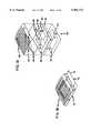
- FIG. 1Ais an exploded view of the wound covering
- FIG. 1Billustrates an assembled view of the wound covering of FIG. 1A
- FIGS. 2A and 2Bis a view of an alternate wound covering
- FIG. 3Ais an exploded view of an alternate wound covering
- FIG. 3Bis an assembly view of the wound covering of FIG. 3A;
- FIG. 4is a side elevation view of a wound covering
- FIG. 5is an enlarged top plan view of a wound covering
- FIG. 6is an enlarged sectional view taken along line A--A of FIG. 5;
- FIG. 7is a bottom view of the wound covering of FIG. 4;
- FIG. 8Ais an exploded view of an alternate wound covering:
- FIG. 8Bis an assembly view showing the air flow through the wound covering
- FIG. 9Ais a perspective view of an alternate wound covering
- FIG. 9Bis a side view of the wound covering of FIG. 9A;
- FIG. 10is a perspective view of an alternate wound covering
- FIG. 11Ais a perspective view of an alternate wound covering
- FIG. 11Bis a side cross-sectional view of the wound covering of FIG. 11A;
- FIG. 11Cis a view of the wound covering of FIG. 11A;
- FIG. 12is a perspective view of an alternate connector apparatus for the wound covering
- FIG. 13Ais an alternate connector arrangement for the wound covering
- FIG. 13Bis a side sectional view of the wound covering of 13A;
- FIG. 14is a view of a rigid connector for engagement with a wound covering
- FIG. 15is an alternate fluid inlet line for the wound covering
- FIG. 16Ais a view of a two ply barrier layer wound covering
- FIG. 16Bis a cross-sectional view of the wound covering of 16A
- FIG. 17is an alternate wound covering
- FIG. 18Ais an alternate wound covering
- FIG. 18Bis a side sectional view of the wound covering of FIG. 18A.
- FIG. 19is a view of an alternate wound covering.
- the present inventionis directed to a non-contact wound covering for controlling the local environment at a wound site on a patient.
- the wound coveringprotects the wound from contamination by materials from the outside environment and also prevents the wound from site from sheading contaminants into the local environment of the patient, i.e. the hospital room.
- the treatment volume formed over the wound sitecan be controlled to create an optimal healing environment.
- woundrefers generically to surgical incisions, ulcers, or other lesions or breaks in the skin.
- Each embodiment of the wound coveringincludes three basic element.
- First a vertical wallis provided to encircle the wound area on the surface of the patient's skin.
- This vertical structureis self supporting and provides an upper surface to support a barrier layer above the level of the wound.
- This structureis referred to throughout as the peripheral sealing ring.
- the next elementis a barrier layer which is attached to the peripheral sealing ring. Together these elements form an enclosure or wound treatment volume over the wound site. The fact the barrier layer does not contact the wound itself promotes healing by minimizing mechanical stresses on the tissues.
- the barrier layerspans the entire wound area and attaches to the peripheral sealing ring.
- the third elementis an adhesive and a complimentary release liner assembly which is attached to the lower surface of the sealing ring to facilitate attachment of the wound covering to the skin of the patient.
- the three basic components of the wound coveringare combined with other elements to provide an optimal healing environment at the wound site.
- the climate within the wound treatment volumemay be controlled. Typically the temperature, humidity, and gas composition is controlled. Also aerosolized medications or compounds can be released into this volume as well.
- the above listis exemplary of the climate controls which may promote healing of the wound, and is not intended to limit the scope of the present invention. It will be understood by those skilled in the art that numerous other climate factors can be controlled within the treatment volume of the present wound covering system without departing from the scope of the invention.
- FIG. 1Aillustrates an exploded view of the wound covering 50.
- the peripheral sealing ring 52is substantially square in outline.
- the peripheral sealing ring 52is intended to be attached to uninjured skin surrounding the wound area 54 using an adhesive 56.
- a layer of adhesive hydrogelis shown as the adhesive 56.
- the peripheral sealing ring 52is preferably constructed of an open cell hydrophilic foam plastic having a sealed outer surface 58 which isolates the wound from the environment.
- the peripheral sealing ringis fabricated from a material which is stiff but which may conform to the curved surface of the patient's body.
- the inner surface 60 of the sealing ring 52is preferably porous or absorbent so that it can form a reservoir to contain and release moisture or water vapor into the air within the treatment volume 62 to create a high humidity environment if desired. Additionally, the hydrophilic absorbent nature of the peripheral sealing ring 52 absorbs fluids and blood weeping from the wound.
- a barrier layer 64is preferably attached to the upper surface 66 of the peripheral sealing ring 52 to seal the treatment volume 62.
- the barrier layer 64is preferably constructed of a clear flexible plastic film, such as polyethylene or polyvinylchloride.
- a wound tracing grid 68also constructed of a clear flexible material, may optionally be attached to the barrier layer 64 so that the physician can draw the wound as an aid to track the healing process of the wound.
- the wound tracing gridpreferably contains a labeling area 70 for identifying the patient, date when the wound was traced, and other patient medical data.
- the volume of the peripheral sealing ring 52will depend on the structural strength of the support material and the amount of fluid absorption desired. Additionally, the total area of the peripheral sealing ring 52 is dependent on the size of the wound. For example, larger wounds and more flexible covers will require a thicker sealing ring so that the center of the cover does not touch the wound.
- the upper surface 66 of the peripheral sealing ring 52is preferably sealed by extending the barrier layer 64 over the entire upper surface 66 as seen in the drawing.
- the adhesive 56 for attaching the peripheral sealing ring 52 to the wound area 54may take any form however the preferred adhesive is a preferably a two-faced hydrogel which attaches to the lower surface 72 of the peripheral sealing ring 52. This adhesive 56 permits the attachment of the peripheral sealing ring 52 to the patient's skin.
- the peripheral sealing ring 52may serve as a reservoir for retaining water or medicaments in the treatment volume 62 in order to maintain a high humidity in the air within the volume. Water may be added to the peripheral sealing ring 52 at any time during treatment.
- peripheral sealing ring 52can be supplied in a variety of shapes and sizes to accommodate various wounds.
- the shapesmay include circles, squares, or rectangles.
- individual segments of peripheral ring materialcould be assembled into any shape necessary to form a perimeter around the wound area.
- the barrier layer 64 and wound tracing grid 68could be provided in large sheets which may be cut to size and then attached to the peripheral sealing ring.
- FIG. 1Bis an assembled view of the wound covering 50 of FIG. 1A.
- a release liner 74is applied to the adhesive 56.
- the release linermay span the entire lower surface of the covering to maintains the sterility of the treatment volume 62.
- the release liner 74preferably has a grip tab 76 to facilitate removal of the liner 74 from the wound covering 50 immediately prior to application of the wound covering 50 to the patient.
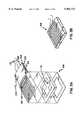
- FIGS. 2A and 2Billustrate an alternate embodiment of the wound covering 80 utilizing passive heating of the treatment volume 62. Because heat is constantly being radiated from the body surface, the insulation properties of the trapped air within the treatment volume 62 will reduce this heat loss. By adding an infrared reflector 82 over the treatment volume 62, the infrared heat from the body can be reflected back to the skin for added passive heating.
- One edge 84 of the wound tracing grid 86is preferably not attached to the barrier layer to form an envelope or pocket 94 between the wound tracing grid 86 and the barrier layer.
- a piece of reflective foil material 88may be inserted into the pocket 94.
- a thin layer of insulating material 90may optionally be attached to the foil layer 88 to enhance heat retention and to provide the foil layer 88 with additional resiliency.
- a tab 92is preferably attached to the infrared reflector 82 to allow easy insertion and removal from the pocket 94 and the wound covering 80.
- FIGS. 3A and 3Billustrate an alternate embodiment of a non-contact wound covering 108 utilizing active heating of the treatment volume 112.
- Small to medium sized woundsmay be safely and easily heated utilizing the foil heater assembly 100.
- the heater assembly 100preferably comprises a pressure-sensitive switch 102, an insulating layer 104, and a foil heater element 106.
- the pressure-sensitive switch 102is preferably laminated to the upper layer of the heater assembly 100.
- the purpose of the switch 102is to shut off power to the heater element 106 in the event that external pressure is applied to the wound covering 108 with sufficient force to cause the heater element 106 to contact the skin or wound below. This is an important feature to prevent the possibility of applying heat and pressure to the skin at the same time.
- the combination of heat and pressureis known to cause burns even at low temperatures (40° C.) because the pressure prevents blood flow in the skin making it susceptible to thermal injury.
- the pressure-sensitive switch 102preferably covers the whole heater assembly 100 so that pressure applied anywhere to the surface of the heater assembly 100 will deactivate the heater element 106.
- force sensing resistorsresemble a membrane switch which changes resistance inversely with applied force.
- Devices of this typeoffer the substantial advantage of being low cost, flexible, and durable. It will be understood by those skilled in the art that a variety of other force sensing switch devices may be utilized as well.
- the heater element 106is preferably a thin film type resistance heater which is commercially available. Such thin film resistance heaters utilize low voltage, minimizing the electrical risk to the patient and allowing for battery-powered mobility.
- the heater element 106is preferably sized for each wound covering 108. In actual use,the foil heater element 106 is preferably provided in large sheets with a pair of electrical leads 110 along one edge.
- the foil heater assembly 100is preferably inserted into a pocket 114 formed between the wound tracing grid 86 and the barrier layer as discussed above.
- a temperature monitoring devicesuch as a liquid crystal temperature monitor, may be applied to an upper surface of the foil heater assembly 100 or within the treatment volume 112 to monitor the temperature within the treatment volume 112.
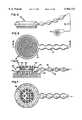
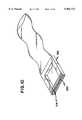
- FIG. 4 and FIG. 5,illustrate an alternate embodiment of the wound covering 10.
- the wound covering 10includes a generally circular head, designated generally at 12, which transitions to an elongated non-kinking, collapsible air supply or hose 14.
- the apparatusas illustrated in FIG. 4, is connected by suitable supply line or tube 16 to a source 18 of thermally controlled air which is schematically illustrated.
- the term air as used hereinis intended to encompass mixtures of gases of controlled composition.
- the apparatusis constructed to apply a continuous stream of thermally controlled air to a wound treatment volume. While the apparatus was conceived and constructed for applying a heated stream of air, it may also be used to apply a cooled stream of air if required.
- FIG. 4 and FIG. 5The overall appearance of the wound covering is best seen in FIG. 4 and FIG. 5. It is preferred to construct the apparatus from top and bottom sheets of thin heat-sealable polymer film which overly one another.
- a top sheet or membrane 20overlies a bottom sheet or membrane 22 and they are heat sealed together along a plurality of seal lines, including a continuous outer seam 24, which extends in a circle around the head 12 and continues in a sinusoidal or convoluted fashion along and forming the air tube portion 14.
- An inner continuous circular seam 26is provided as best seen in FIG. 6 and in FIG. 7. This inner seam secures the sheets together along a continuous circle to form the inner wall of a torus defining a supply volume 28.
- the inner circular portion of the two sheets lying in the plane within the center of the supply volume 28forms a wall 30 separating a lower wound treatment volume 32, from an upper insulation chamber 34.
- the wall 30includes multiple apertures 36 formed by making small circular seals 38 and cutting and removing circular portions within the circular seals 38.
- a wall 30 with a plurality of apertures 36is formed between the wound treatment volume 32 and insulation chamber 34.
- a plurality of apertures 40are formed in the common circular wall surrounding the treatment volume 32 for distributing and conveying heated air or gases from the supply volume 28 into the wound treatment volume 32.
- the heated air flowing into the treatment volume 32bathes and contacts the wound surface of a patient's body 42.
- the aircirculates throughout the wound treatment volume 32, and then passes through the apertures 36 into the upper or insulating chamber 34, where it then passes through a circular filter 44 forming an outer wall of the insulation chamber 34.
- the filter 44filters the air leaving the wound treatment volume to trap contaminants shed from the wound.
- the filter 44may be constructed of a filter paper bonded along its periphery to the outer tangential walls of the housing forming the torus or supply chamber 28.
- the filter paperalso provides an insulating layer which suppresses loss of heat by radiation through the upper wall 30.
- the lower surface of the head 12 as shown in FIG. 6 and FIG. 7,is preferably provided with a peripheral sealing ring 46 made of an absorbent material such as foam and bonded by suitable adhesive to the walls of the housing and the skin of the patient around the wound.
- the foam or cotton peripheral sealing ring 46is provided with a peel-off tape so that it adheres to the wall of the housing and on the other side to the skin of the patient.
- the adhesive or tapeholds the apparatus in place and prevents airflow escape between the device and the skin of the patient.
- the absorbent material of the ringabsorbs weeping blood and fluids and insulates the skin from direct heat in the tube.
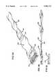
- the supply hose 14is designed to be non-kinking by forming it of symmetrically convoluted flexible material.
- the hose and housingare integrally formed essentially of a unitary structure, such as a thin film membrane.
- the supply hose section 14is inflatable upon the application of heated air through the supply line 16. The indentations in the hose section 14 permit it to bend without kinking and, thus, differentiate from a straight tubular hose which may kink when bent.
- the thermal body treatment apparatus of the invention and the supply hose sectionare formed from two, thin, sealed-together membranes, the hose, and in fact the entire apparatus, is collapsible. This prevents the possibility of applying heat and pressure to the skin as might happen if a disoriented patient rolled over on the device. Instead, the weight of the patient's body would collapse the device, obstructing the flow of air, and preventing the application of heat.
- the film membranemay preferably be transparent to enable viewing the wound without removal. However for cosmetic reasons the barrier layer may be opaque.
- the filter paper 44is attached across the tangential surfaces of the toroidal housing, thus providing a large area of filter for the escaping air.
- the head of the apparatusmaybe about one foot in diameter for most applications. However, it may be made smaller for certain other applications.
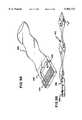
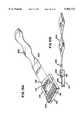
- FIG. 8Aillustrates an exploded view of an alternate embodiment of a non-contact wound covering 120 with climate control within the treatment volume 122.
- An inflatable structure 124is preferably attached to a fluid inlet line 126 at a fluid inlet port 129 on the perimeter of the inflatable structure 124.
- the inflatable structure 124is preferably attached to an absorbent peripheral sealing ring 128, which is in turn attached to the wound area 54 by a suitable adhesive 56.
- the peripheral sealing ring 128preferably has a sealed outer surface and a porous inner surface which performs the same function as the peripheral sealing ring 52 discussed above.
- a barrier layer 130 having an exhaust filter 132is attached to top surface 134 on the inflatable structure 124.
- a gas illustrated by the arrows Ais introduced into the inflatable structure 124 from an external source (not shown) through the inlet line 126.
- the gaspressurizes the inflatable structure 124 in order to maintain the barrier layer 130 and exhaust filter 132 in an elevated position relative to the wound area 54.
- the inner surface 136 of the inflatable structure 124preferably has a plurality of apertures 138 through which the fluid is introduced into the wound treatment volume 122. As the pressure within the treatment chamber increases, excess pressure is relieved through the exhaust filter 132. In this fashion, various fluids or gases can be introduced into the wound treatment volume 122.
- oxygenmay be introduced into the treatment volume 122 through the apertures 138 of the inflatable structure 124.
- the presence of oxygen within the wound treatment volume 122may increase the oxygen available to the superficial layer of growing cells in the wound area 54.
- Nitric oxidemay alternatively be infused into the treatment volume 122.
- Nitric oxide (NO)is a potent vasodilator which in theory may be absorbed across the wound surface and increase localized blood flow. A very small concentration of NO (parts per million) may provide this effect. NO may also be pre-absorbed into the absorbent peripheral sealing ring 128 and then allowed to passively diffuse into the volume once it is applied to the wound.
- gaseous or aerosolized medications or compoundsmay be introduced into the gas flow entering the treatment volume 122.
- FIG. 9A and FIG. 9Billustrate an alternate embodiment of the climate control system discussed above wherein a fluid inlet line 140 may form part of a barrier layer 142
- the barrier layer 142is unitary with the fluid inlet line 140 and is preferably attached to an exhaust filter media 144 to allow excess pressure to be released from the wound treatment volume 146.
- the filter media 144forms part of the barrier 142.
- the arrows "A" in FIG. 9Billustrate the movement of the fluid though the fluid inlet line 140, the treatment volume 146, and the exhaust filter 144.
- FIG. 10illustrates an alternate embodiment wherein an exhaust filter 154 is retained in a recess 150 formed in one side of a peripheral sealing ring 152. This structure allows the excess fluid to be exhausted through the side of the peripheral sealing ring 152, rather than through the top, as illustrated in FIG. 9A and 9B.
- FIG. 11Ais a perspective view of the embodiment illustrated in FIG. 9A wherein a connector 160 on the end of a fluid supply line 162 engages with an opening 164 on the fluid inlet line 140.
- FIG. 11Billustrates a side view of the fluid supply line 162 as it engages with the fluid inlet line 140.
- FIG. 11Cillustrates the embodiment of 11A and 11B where the fluid inlet line 140 is folded over the top of the peripheral sealing ring 152 to seal the treatment volume 146 when the supply line 162 is uncoupled.
- FIG. 12illustrates an alternate embodiment in which a fluid inlet slot 170 engages with a rigid connector 172 on a fluid inlet line 174.
- the fluid inlet slot 170forms an opening in one portion of the peripheral sealing ring 176.
- the openingis in fluid communication with the treatment volume 178. This configuration allows for quick disconnect of the fluid inlet line 174 from the wound covering 180 to provide the patient with additional mobility.
- FIG. 13Ais a perspective view of an alternate non-contact wound covering 190 having a fluid inlet connector 192 attached to a top surface 194 of the peripheral sealing ring 196.
- the fluid inlet connector 192preferably contains an inlet filter media 198.
- a rigid connector 200 on a fluid inlet line 202mates with the fluid inlet connector 192.
- a cover 204extends from the top of the fluid inlet connector 192 across the top of the peripheral sealing ring 196 where it engages with an exhaust filter media 206.
- FIG. 14illustrates the embodiment of FIGS. 13A and 13B utilizing a non-disposable fluid supply line 210.
- FIG. 15illustrates an alternate embodiment which utilizes a manifold structure 220 as part of the fluid inlet line 222 to provide even distribution of the fluid being introduced into the treatment volume 224.
- the fluid inlet line 222preferably has a series of seals 226 along its edge which are interrupted by a plurality of side openings 228 from which the fluid can be transmitted into the treatment volume 224.
- the embodiment disclosed in FIG. 15illustrates an exhaust filter 230 recessed into the side of the peripheral sealing ring 232.
- exhaust filter configurationsare possible with the disclosed manifold structure 220.
- FIGS. 16A and 16Billustrate an alternate wound covering 240 with a top barrier layer 242 and a lower layer 244 having a plurality of holes 246.
- the top coverforms the barrier layer 242 and it extends substantially across the area of the peripheral sealing ring 248.
- the lower layer 244likewise extends across the peripheral sealing ring 248.
- An upper insulating layer 250is formed between the lower layer 244 and the top of the barrier layer 242. Fluid in the fluid inlet line 252 is directed into the upper insulating layer 250.
- the pressurized fluid in the upper insulating layer 250passes through the holes 246 into the treatment volume 254.
- the holes 246 in the lower layer 244provide generally even distribution of the fluid within the wound treatment volume 254.
- An optional seal 258may be formed in the center portion of the barrier layer 242 and the lower layer 244 to provide the layers with additional structural support.
- An exhaust filter medium 256is provided in a recess along one side of the peripheral sealing ring 248 to relieve pressure in the treatment volume 254.
- FIG. 17illustrates an alternate embodiment of a non-contact wound covering 260 utilizing semi-rigid supports 262 to retain the barrier layer 264 above the wound area.
- semi-rigid supports 262may be utilized for this application.
- plastic or resilient rubber materialsmay provide sufficient support to the barrier layer 264 with a minimum risk of injuring the patient.
- FIG. 18A and FIG. 18Billustrate an alternate exhaust filter medium 270 with an enlarged surface area to accommodate larger volumes of air flow through the non-contact wound covering 280.
- the exhaust filteris incorporated into the fluid inlet line 272.
- the fluid inlet line 272also forms a portion of the barrier layer 274, which is in turn attached to the peripheral sealing ring 276.
- fluid illustrated as the arrows "A"is introduced into the fluid inlet line 272, where it is directed into the wound treatment volume 278, past the wound area and out through the exhaust filter medium 270.
- FIG. 19illustrates a bi-directional line 290 with a center divider 292. Fluid is introduced into the fluid inlet line 294 where it proceeds through a fluid inlet port 296 into the treatment volume 298. The fluid then is forced through a fluid outlet port 300 where it is driven away from the treatment volume 298 in a fluid outlet line 302. It will be understood by those skilled in the art that it would be possible to utilize separate fluid inlet and outlet lines to achieve the same result.
Landscapes
- Health & Medical Sciences (AREA)
- Animal Behavior & Ethology (AREA)
- Veterinary Medicine (AREA)
- Engineering & Computer Science (AREA)
- Biomedical Technology (AREA)
- Heart & Thoracic Surgery (AREA)
- Public Health (AREA)
- Life Sciences & Earth Sciences (AREA)
- General Health & Medical Sciences (AREA)
- Vascular Medicine (AREA)
- Thermal Sciences (AREA)
- Physics & Mathematics (AREA)
- Epidemiology (AREA)
- Anesthesiology (AREA)
- Hematology (AREA)
- Media Introduction/Drainage Providing Device (AREA)
Abstract
Description
Claims (9)
Priority Applications (1)
| Application Number | Priority Date | Filing Date | Title |
|---|---|---|---|
| US09/172,570US5964721A (en) | 1995-02-21 | 1998-10-14 | Wound covering |
Applications Claiming Priority (3)
| Application Number | Priority Date | Filing Date | Title |
|---|---|---|---|
| US35632595A | 1995-02-21 | 1995-02-21 | |
| US08/999,353US5947914A (en) | 1995-02-21 | 1997-12-29 | Wound covering |
| US09/172,570US5964721A (en) | 1995-02-21 | 1998-10-14 | Wound covering |
Related Parent Applications (1)
| Application Number | Title | Priority Date | Filing Date |
|---|---|---|---|
| US08/999,353DivisionUS5947914A (en) | 1992-06-19 | 1997-12-29 | Wound covering |
Publications (1)
| Publication Number | Publication Date |
|---|---|
| US5964721Atrue US5964721A (en) | 1999-10-12 |
Family
ID=23401003
Family Applications (4)
| Application Number | Title | Priority Date | Filing Date |
|---|---|---|---|
| US08/999,353Expired - LifetimeUS5947914A (en) | 1992-06-19 | 1997-12-29 | Wound covering |
| US09/172,570Expired - LifetimeUS5964721A (en) | 1995-02-21 | 1998-10-14 | Wound covering |
| US09/272,181Expired - LifetimeUS5961480A (en) | 1992-06-19 | 1999-03-18 | Wound covering |
| US09/411,802Expired - LifetimeUS6241697B1 (en) | 1992-06-19 | 1999-10-04 | Wound covering |
Family Applications Before (1)
| Application Number | Title | Priority Date | Filing Date |
|---|---|---|---|
| US08/999,353Expired - LifetimeUS5947914A (en) | 1992-06-19 | 1997-12-29 | Wound covering |
Family Applications After (2)
| Application Number | Title | Priority Date | Filing Date |
|---|---|---|---|
| US09/272,181Expired - LifetimeUS5961480A (en) | 1992-06-19 | 1999-03-18 | Wound covering |
| US09/411,802Expired - LifetimeUS6241697B1 (en) | 1992-06-19 | 1999-10-04 | Wound covering |
Country Status (1)
| Country | Link |
|---|---|
| US (4) | US5947914A (en) |
Cited By (54)
| Publication number | Priority date | Publication date | Assignee | Title |
|---|---|---|---|---|
| US6095992A (en)* | 1998-04-06 | 2000-08-01 | Augustine Medical, Inc. | Wound treatment apparatus for normothermic treatment of wounds |
| US6458109B1 (en) | 1998-08-07 | 2002-10-01 | Hill-Rom Services, Inc. | Wound treatment apparatus |
| US20020169406A1 (en)* | 2001-05-10 | 2002-11-14 | Donald Stapf | Minimal contact treatment device |
| US6685681B2 (en) | 2000-11-29 | 2004-02-03 | Hill-Rom Services, Inc. | Vacuum therapy and cleansing dressing for wounds |
| US6755807B2 (en) | 1999-11-29 | 2004-06-29 | Hill-Rom Services, Inc. | Wound treatment apparatus |
| US20040260253A1 (en)* | 2003-06-18 | 2004-12-23 | Rosati Coni F. | Method and apparatus for supplying gas to an area |
| US6855135B2 (en) | 2000-11-29 | 2005-02-15 | Hill-Rom Services, Inc. | Vacuum therapy and cleansing dressing for wounds |
| US6920881B2 (en) | 2000-06-27 | 2005-07-26 | Vinod Narula | Wound covering pressure relief pads |
| US7008445B2 (en) | 2002-04-29 | 2006-03-07 | Medcool, Inc. | Method and device for rapidly inducing hypothermia |
| US7022113B2 (en) | 2001-07-12 | 2006-04-04 | Hill-Rom Services, Inc. | Control of vacuum level rate of change |
| US7052509B2 (en) | 2002-04-29 | 2006-05-30 | Medcool, Inc. | Method and device for rapidly inducing and then maintaining hypothermia |
| US20060200100A1 (en)* | 2003-06-18 | 2006-09-07 | Rosati Coni F | Method and apparatus for supplying gas to an area |
| US20060235347A1 (en)* | 2005-04-16 | 2006-10-19 | Adel Aali | Deformable and conformable wound protecting apparatus and its method of application |
| US7195624B2 (en) | 2001-12-26 | 2007-03-27 | Hill-Rom Services, Inc. | Vented vacuum bandage with irrigation for wound healing and method |
| US20070068536A1 (en)* | 2005-09-29 | 2007-03-29 | Rawski Mark V | Surgical incision protection device |
| US20070142761A1 (en)* | 2005-12-15 | 2007-06-21 | Adel Aali | Wound shield |
| US20070142757A1 (en)* | 2005-12-15 | 2007-06-21 | Adel Aali | Wound shield and warming apparatus and method |
| US20070161938A1 (en)* | 2006-01-12 | 2007-07-12 | Adel Aali | Dressing substrate |
| US20070166357A1 (en)* | 2006-01-16 | 2007-07-19 | Shaffer Thomas H | Bandage For Facilitating Transdermal Respiration And Healing |
| US20070191754A1 (en)* | 2006-02-13 | 2007-08-16 | Adel Aali | Wound shield |
| US7338482B2 (en) | 2002-02-28 | 2008-03-04 | Hill-Rom Services, Inc. | External catheter access to vacuum bandage |
| US7534927B2 (en) | 2001-12-26 | 2009-05-19 | Hill-Rom Services, Inc. | Vacuum bandage packing |
| US20090173340A1 (en)* | 2007-05-24 | 2009-07-09 | Embrace Llc | Method and Apparatus to Relieve Menstrual Pain |
| US20090205648A1 (en)* | 2008-02-19 | 2009-08-20 | Portaero, Inc. | Pneumostoma management system with secretion management features for treatment of chronic obstructive pulmonary disease |
| US7678090B2 (en) | 1999-11-29 | 2010-03-16 | Risk Jr James R | Wound treatment apparatus |
| US7723560B2 (en) | 2001-12-26 | 2010-05-25 | Lockwood Jeffrey S | Wound vacuum therapy dressing kit |
| US7726317B1 (en)* | 2007-10-02 | 2010-06-01 | Yvonne Garcia | Apparatus to protect a piercing |
| US7763000B2 (en) | 1999-11-29 | 2010-07-27 | Risk Jr James R | Wound treatment apparatus having a display |
| US7871427B2 (en) | 2005-02-08 | 2011-01-18 | Carewave, Inc. | Apparatus and method for using a portable thermal device to reduce accommodation of nerve receptors |
| US20110015708A1 (en)* | 2007-05-24 | 2011-01-20 | Embrace, Llc | Method and apparatus to relieve menstrual pain |
| US20110041839A1 (en)* | 2007-05-24 | 2011-02-24 | Embrace, Llc | Compression undergarment for relief of menstrual pain and related method of use |
| US7896856B2 (en) | 2002-08-21 | 2011-03-01 | Robert Petrosenko | Wound packing for preventing wound closure |
| US7910791B2 (en) | 2000-05-22 | 2011-03-22 | Coffey Arthur C | Combination SIS and vacuum bandage and method |
| US7927318B2 (en) | 2001-10-11 | 2011-04-19 | Risk Jr James Robert | Waste container for negative pressure therapy |
| US7931651B2 (en) | 2006-11-17 | 2011-04-26 | Wake Lake University Health Sciences | External fixation assembly and method of use |
| US8067662B2 (en) | 2009-04-01 | 2011-11-29 | Aalnex, Inc. | Systems and methods for wound protection and exudate management |
| US8168848B2 (en) | 2002-04-10 | 2012-05-01 | KCI Medical Resources, Inc. | Access openings in vacuum bandage |
| US8252971B2 (en) | 2009-07-16 | 2012-08-28 | Aalnex, Inc. | Systems and methods for protecting incisions |
| US8267960B2 (en) | 2008-01-09 | 2012-09-18 | Wake Forest University Health Sciences | Device and method for treating central nervous system pathology |
| US8377016B2 (en) | 2007-01-10 | 2013-02-19 | Wake Forest University Health Sciences | Apparatus and method for wound treatment employing periodic sub-atmospheric pressure |
| US8415523B2 (en) | 2005-04-16 | 2013-04-09 | Aalnex, Inc. | Secondary wound dressings for securing primary dressings and managing fluid from wounds, and methods of using same |
| US8454671B2 (en) | 2002-12-12 | 2013-06-04 | Medcool, Inc. | Method and apparatus for reducing body temperature of a subject |
| US8529613B2 (en) | 2006-10-18 | 2013-09-10 | Medcool, Inc. | Adjustable thermal cap |
| US8579953B1 (en) | 2007-12-07 | 2013-11-12 | Peter J. Dunbar | Devices and methods for therapeutic heat treatment |
| US8591447B2 (en) | 2010-06-29 | 2013-11-26 | Jennifer DiGrazia | Wound and bandage protection system and method |
| US8834520B2 (en) | 2007-10-10 | 2014-09-16 | Wake Forest University | Devices and methods for treating spinal cord tissue |
| US9107753B2 (en) | 2007-05-24 | 2015-08-18 | Ziivaa Ip, Llc | Method to relieve menstrual pain |
| US9289193B2 (en) | 2008-07-18 | 2016-03-22 | Wake Forest University Health Sciences | Apparatus and method for cardiac tissue modulation by topical application of vacuum to minimize cell death and damage |
| US10351238B2 (en) | 2014-03-13 | 2019-07-16 | Endurant Systems LLC. | UAV configurations and battery augmentation for UAV internal combustion engines, and associated systems and methods |
| US10583228B2 (en) | 2015-07-28 | 2020-03-10 | J&M Shuler Medical, Inc. | Sub-atmospheric wound therapy systems and methods |
| US10596041B2 (en) | 2014-08-28 | 2020-03-24 | Ascension Texas | Apparatuses and methods for minimizing wound dehiscence, scar spread, and/or the like |
| US10603208B2 (en) | 2011-01-21 | 2020-03-31 | Carewave Medical, Inc. | Modular stimulus applicator system and method |
| US11160917B2 (en) | 2020-01-22 | 2021-11-02 | J&M Shuler Medical Inc. | Negative pressure wound therapy barrier |
| US12296129B2 (en) | 2018-03-07 | 2025-05-13 | Soovu Labs, Inc. | Systems and methods for improved pain relief from stimulation of thermal fibers |
Families Citing this family (66)
| Publication number | Priority date | Publication date | Assignee | Title |
|---|---|---|---|---|
| US5947914A (en)* | 1995-02-21 | 1999-09-07 | Augustine Medical, Inc. | Wound covering |
| US5964723A (en)* | 1992-06-19 | 1999-10-12 | Augustine Medical, Inc. | Normothermic tissue heating wound covering |
| US7928281B2 (en) | 1992-06-19 | 2011-04-19 | Arizant Technologies Llc | Wound covering |
| US6465708B1 (en)* | 1992-06-19 | 2002-10-15 | Augustine Medical, Inc. | Covering |
| US6093160A (en)* | 1994-11-21 | 2000-07-25 | Augustine Medical, Inc. | Flexible non-contact wound treatment device |
| US20050143797A1 (en) | 2003-07-18 | 2005-06-30 | Thermotek, Inc. | Compression sequenced thermal therapy system |
| US9119705B2 (en) | 1998-06-08 | 2015-09-01 | Thermotek, Inc. | Method and system for thermal and compression therapy relative to the prevention of deep vein thrombosis |
| US7087807B2 (en)* | 1999-11-10 | 2006-08-08 | Arizant Technologies, Llc | Tissue treatment device for an extremity |
| US6528697B1 (en)* | 2000-01-03 | 2003-03-04 | Augustine Medical, Inc. | Modular bandage |
| US7338515B2 (en)* | 2000-04-10 | 2008-03-04 | Arizant Healthcare Inc. | System, combination and method for controlling airflow in convective treatment |
| US6992233B2 (en)* | 2002-05-31 | 2006-01-31 | Medafor, Inc. | Material delivery system |
| US7201766B2 (en)* | 2002-07-03 | 2007-04-10 | Life Support Technologies, Inc. | Methods and apparatus for light therapy |
| US7001413B2 (en)* | 2002-07-03 | 2006-02-21 | Life Support Technologies, Inc. | Methods and apparatus for light therapy |
| US8346367B2 (en) | 2002-09-11 | 2013-01-01 | Meagan Medical, Inc. | Apparatus and method for stabilizing, improving mobility, and controlling cartilage matrix degradation of weight-bearing articular joints |
| US8060210B1 (en) | 2002-09-11 | 2011-11-15 | International Rehabilitative Sciences, Inc. | Methods for improving mobility and controlling cartilage matrix degradation of weight-bearing articular joints |
| GB2418025B (en)* | 2003-06-06 | 2006-09-20 | James Rosser | Device for the prevention or treatment of ulcers |
| US8251057B2 (en) | 2003-06-30 | 2012-08-28 | Life Support Technologies, Inc. | Hyperbaric chamber control and/or monitoring system and methods for using the same |
| US8128672B2 (en) | 2006-05-09 | 2012-03-06 | Thermotek, Inc. | Wound care method and system with one or both of vacuum-light therapy and thermally augmented oxygenation |
| US8100956B2 (en)* | 2006-05-09 | 2012-01-24 | Thermotek, Inc. | Method of and system for thermally augmented wound care oxygenation |
| US8574278B2 (en) | 2006-05-09 | 2013-11-05 | Thermotek, Inc. | Wound care method and system with one or both of vacuum-light therapy and thermally augmented oxygenation |
| US8778005B2 (en) | 2003-07-18 | 2014-07-15 | Thermotek, Inc. | Method and system for thermal and compression therapy relative to the prevention of deep vein thrombosis |
| US6962600B2 (en)* | 2003-08-04 | 2005-11-08 | Medcool, Inc. | Method and apparatus for reducing body temperature of a subject |
| US7761945B2 (en) | 2004-05-28 | 2010-07-27 | Life Support Technologies, Inc. | Apparatus and methods for preventing pressure ulcers in bedfast patients |
| US10016583B2 (en) | 2013-03-11 | 2018-07-10 | Thermotek, Inc. | Wound care and infusion method and system utilizing a thermally-treated therapeutic agent |
| USD679023S1 (en) | 2004-07-19 | 2013-03-26 | Thermotek, Inc. | Foot wrap |
| US10765785B2 (en) | 2004-07-19 | 2020-09-08 | Thermotek, Inc. | Wound care and infusion method and system utilizing a therapeutic agent |
| US20060034053A1 (en) | 2004-08-12 | 2006-02-16 | Thermotek, Inc. | Thermal control system for rack mounting |
| US20080269852A1 (en)* | 2005-04-07 | 2008-10-30 | Medcool, Inc | Methods and Apparatus for Thermal Regulation of a Body |
| US8197447B2 (en)* | 2005-04-19 | 2012-06-12 | Venetec International, Inc. | Flexible IV site protector |
| US8100862B2 (en)* | 2005-05-18 | 2012-01-24 | Venetec International, Inc. | Insertion site protection device |
| US7988673B2 (en) | 2005-07-14 | 2011-08-02 | Venetec International, Inc. | Protective dressing and methods of use thereof |
| WO2007019569A2 (en)* | 2005-08-09 | 2007-02-15 | International Rehabilitative Sciences, Inc. | An apparatus for surface electrical stimulation and stabilization to treat disorders of the joints |
| DE102005048618B4 (en)* | 2005-10-11 | 2008-08-21 | Heinz Kurz Gmbh Medizintechnik | Auditory ossicle prosthesis with elastic swivel joint |
| AU2012216810B2 (en)* | 2005-12-15 | 2014-04-10 | Adel Aali | Wound shield and wound warming apparatus and method |
| AU2011235999B2 (en)* | 2006-02-13 | 2013-11-21 | Adel Aali | Wound shield |
| US9820888B2 (en) | 2006-09-26 | 2017-11-21 | Smith & Nephew, Inc. | Wound dressing |
| US20080097561A1 (en)* | 2006-10-18 | 2008-04-24 | Medcool, Inc. | Dual cycle thermal system and method of use |
| US10188842B2 (en) | 2006-11-21 | 2019-01-29 | Mark R. Moore | Apparatus and method for deploying a surgical preparation |
| US11511094B2 (en) | 2006-11-21 | 2022-11-29 | Mark R. Moore | Apparatus and method for deploying a surgical preparation |
| US8403898B2 (en)* | 2006-11-21 | 2013-03-26 | Mark R. Moore | Apparatus and method for deploying a surgical preparation |
| US10470842B2 (en) | 2006-11-21 | 2019-11-12 | Mark R. Moore | Apparatus and method for deploying a surgical preparation |
| US8758310B2 (en) | 2006-11-21 | 2014-06-24 | Mark R. Moore | Apparatus and method for deploying a surgical preparation |
| USD662212S1 (en) | 2007-04-10 | 2012-06-19 | Thermotek, Inc. | Butterfly wrap |
| US8758419B1 (en) | 2008-01-31 | 2014-06-24 | Thermotek, Inc. | Contact cooler for skin cooling applications |
| US8298200B2 (en) | 2009-06-01 | 2012-10-30 | Tyco Healthcare Group Lp | System for providing continual drainage in negative pressure wound therapy |
| MX2011002861A (en) | 2008-09-18 | 2011-04-26 | Kci Licensing Inc | Therapy delivery systems and methods. |
| TW201014624A (en)* | 2008-09-18 | 2010-04-16 | Kci Licensing Inc | A system and method for delivering reduced pressure to subcutaneous tissue |
| GB0902368D0 (en) | 2009-02-13 | 2009-04-01 | Smith & Nephew | Wound packing |
| US8758291B2 (en)* | 2009-08-07 | 2014-06-24 | Acute Ideas, Inc. | Wound ventilation system |
| US8791315B2 (en) | 2010-02-26 | 2014-07-29 | Smith & Nephew, Inc. | Systems and methods for using negative pressure wound therapy to manage open abdominal wounds |
| US10512587B2 (en) | 2011-07-27 | 2019-12-24 | Thermotek, Inc. | Method and apparatus for scalp thermal treatment |
| AU2012340381B2 (en)* | 2011-11-15 | 2017-04-06 | Solventum Intellectual Properties Company | Medical dressings, systems, and methods with thermally- enhanced vapor transmission |
| WO2013162728A1 (en) | 2012-04-24 | 2013-10-31 | Thermotek, Inc. | Method and system for therapeutic use of ultra-violet light |
| JP6400570B2 (en) | 2012-05-23 | 2018-10-10 | スミス アンド ネフュー ピーエルシーSmith & Nephew Public Limited Company | Apparatus and method for local negative pressure closure therapy |
| CN108186200B (en) | 2012-08-01 | 2021-08-10 | 史密夫及内修公开有限公司 | Wound dressing |
| WO2014020440A1 (en) | 2012-08-01 | 2014-02-06 | Smith & Nephew Plc | Wound dressing |
| US20150190273A1 (en)* | 2013-01-11 | 2015-07-09 | Louis Causley Causley | Medical Device to Control Environmental Conditions for Surgical and Non-Surgical Wounds |
| US10300180B1 (en) | 2013-03-11 | 2019-05-28 | Thermotek, Inc. | Wound care and infusion method and system utilizing a therapeutic agent |
| CN105407932A (en) | 2013-03-15 | 2016-03-16 | 史密夫及内修公开有限公司 | Wound dressing and method of treatment |
| US9669233B2 (en) | 2013-11-11 | 2017-06-06 | Thermotek, Inc. | Method and system for wound care |
| JP6339746B2 (en)* | 2014-12-23 | 2018-06-06 | スリーエム イノベイティブ プロパティズ カンパニー | Configurable convection device |
| CN107106321A (en)* | 2014-12-23 | 2017-08-29 | 3M创新有限公司 | Flexible duct for convection device |
| US20180289556A1 (en)* | 2017-04-11 | 2018-10-11 | Ipcapital Group, Inc. | Wound covering apparatus |
| EP3644914A1 (en) | 2017-06-30 | 2020-05-06 | T J Smith & Nephew Limited | Negative pressure wound therapy apparatus |
| US11696962B2 (en) | 2019-10-16 | 2023-07-11 | Mark R. Moore | Apparatus and method for deploying a preoperative skin disinfection device with integrated drape |
| US11324638B2 (en) | 2021-05-28 | 2022-05-10 | Peter B Andrews | Bandage which enables examining or treating a wound without removing the adhesive |
Citations (89)
| Publication number | Priority date | Publication date | Assignee | Title |
|---|---|---|---|---|
| US222690A (en)* | 1879-12-16 | Improvement in surgical bandages | ||
| US697637A (en)* | 1901-11-12 | 1902-04-15 | John Ellwood Lee | Shield for vaccinations, &c. |
| GB190203090A (en)* | 1902-02-07 | 1902-06-25 | William Hugh Alexander | Improvements in Shields for Protecting Corns, Bunions, or Vaccination Spots. |
| US720812A (en)* | 1901-01-12 | 1903-02-17 | Robert W Johnson | Vaccination-shield. |
| US1384467A (en)* | 1920-01-27 | 1921-07-12 | Electrothermal Company | Bandage |
| US1399095A (en)* | 1919-12-02 | 1921-12-06 | Sr Jean F Webb | Vacuo-thermic-body-treatment appliance |
| GB288220A (en)* | 1927-04-09 | 1928-08-23 | David Sarason | Dressing-ring |
| US1777982A (en)* | 1928-02-20 | 1930-10-07 | Popp Karl | Hot-air mat |
| US1920808A (en)* | 1929-05-10 | 1933-08-01 | Sander Eugen | Surgical bandaging |
| US1979082A (en)* | 1932-04-21 | 1934-10-30 | Gen Electric | Electric heater |
| US2221758A (en)* | 1937-05-12 | 1940-11-19 | Elmquist Francis | Surgical dressing |
| US2443481A (en)* | 1942-10-19 | 1948-06-15 | Sene Leon Paul | Device for the treatment of wounds and the like lesions |
| CH269938A (en)* | 1944-12-11 | 1950-07-31 | Serra Balaguer Jose | Insulating device for abscesses, vaccines and other skin conditions or lesions. |
| US2573791A (en)* | 1947-04-19 | 1951-11-06 | John N M Howells | Heat applying bandage |
| US2577945A (en)* | 1947-12-06 | 1951-12-11 | Atherton Harold Starr | Plaster or bandage for skin application |
| US2599523A (en)* | 1949-07-27 | 1952-06-03 | Dorr Emma Ashton | Shield for bunions and corns |
| US2601189A (en)* | 1949-08-22 | 1952-06-17 | Theodore Backer | Air comforter bed covering |
| US2632443A (en)* | 1949-04-18 | 1953-03-24 | Eleanor P Lesher | Surgical dressing |
| US2706988A (en)* | 1951-11-19 | 1955-04-26 | Jarolux A G | Human body heat treating apparatus |
| US2769892A (en)* | 1953-05-04 | 1956-11-06 | Donald F Collins | Electrical heating device |
| US3026874A (en)* | 1959-11-06 | 1962-03-27 | Robert C Stevens | Wound shield |
| FR1303238A (en)* | 1961-09-07 | 1962-09-07 | Pad | |
| CH378465A (en)* | 1958-07-30 | 1964-06-15 | Scholl Mfg Co Ltd | Wound dressing plasters |
| FR1489127A (en)* | 1966-06-06 | 1967-07-21 | Anne Marie Janny | Advanced dressing |
| FR1527887A (en)* | 1967-03-14 | 1968-06-07 | Improvements to Protective Dressings and Dressing Protectors | |
| US3528416A (en)* | 1967-11-06 | 1970-09-15 | Lawrence J Chamberlain | Protective bandage |
| US3596657A (en)* | 1969-02-14 | 1971-08-03 | William Eidus | Thermally conductive surgical dressing |
| US3610251A (en)* | 1968-07-25 | 1971-10-05 | Riveril Trading Co Ltd | Appliance for the heat treatment of a human being |
| US3610238A (en)* | 1970-04-28 | 1971-10-05 | Us Health Education & Welfare | Wound infection prevention device |
| US3687143A (en)* | 1969-11-11 | 1972-08-29 | Schneeberger Kork Ag | Pressure bandage and a method for producing the pressure bandage |
| US3691646A (en)* | 1971-01-22 | 1972-09-19 | Hector Michael Ruffolo | Hair dryer |
| US3782377A (en)* | 1971-09-07 | 1974-01-01 | Illinois Tool Works | Sterile plastic shield |
| US3814095A (en)* | 1972-03-24 | 1974-06-04 | H Lubens | Occlusively applied anesthetic patch |
| US3867939A (en)* | 1972-05-18 | 1975-02-25 | Moore Perk Corp | Disposable, sterile temperature control applicator pad for medical application |
| US3881477A (en)* | 1973-08-07 | 1975-05-06 | Nichols Henry E | Fluid discharge appliance for maintaining a sterile enclosure |
| US4080971A (en)* | 1976-07-30 | 1978-03-28 | Rory Ann Leeper | Battery powered foot warming insole |
| US4134399A (en)* | 1977-06-13 | 1979-01-16 | Alfred Halderson | Skin protective device |
| US4172495A (en)* | 1977-08-03 | 1979-10-30 | Energy Systems Corporation | Slurry cooling of helmets |
| US4279255A (en)* | 1980-02-26 | 1981-07-21 | John F. Taylor | Localized body heat applicator device |
| GB2082919A (en)* | 1980-09-04 | 1982-03-17 | Jones Leslie Bernard | Wound dressings |
| US4341209A (en)* | 1981-01-12 | 1982-07-27 | The Kendall Company | Adhesive bandage with foam backing |
| DE3102674A1 (en)* | 1981-01-28 | 1982-09-02 | Walter Dr.-Ing. 5100 Aachen Jürgens | Bandaging material |
| DE3118232A1 (en)* | 1981-05-08 | 1982-11-18 | Hestia Pharma GmbH, 6800 Mannheim | Skin dressing |
| US4382441A (en)* | 1978-12-06 | 1983-05-10 | Svedman Paul | Device for treating tissues, for example skin |
| US4399816A (en)* | 1980-03-17 | 1983-08-23 | Spangler George M | Wound protector with transparent cover |
| FR2544202A1 (en)* | 1983-04-15 | 1984-10-19 | Od Proizv Ob Cholodil Mash | Burns treatment equipment |
| US4484574A (en)* | 1984-01-25 | 1984-11-27 | Keene Corporation | Self-rolled foam tape without release layer and method of making same |
| US4517972A (en)* | 1983-01-11 | 1985-05-21 | Finch Jr Robert E | Method and apparatus for applying a therapeutic article to a body |
| US4540412A (en)* | 1983-07-14 | 1985-09-10 | The Kendall Company | Device for moist heat therapy |
| US4572188A (en)* | 1984-03-05 | 1986-02-25 | Augustine Scott D | Airflow cover for controlling body temperature |
| US4628930A (en)* | 1985-10-24 | 1986-12-16 | Williams Steven N | Soothing comfort girdle |
| US4633863A (en)* | 1985-09-27 | 1987-01-06 | Filips Chester P | Arterial anchor bandage |
| US4641643A (en)* | 1986-04-28 | 1987-02-10 | Greer Leland H | Resealing skin bandage |
| US4641641A (en)* | 1985-09-13 | 1987-02-10 | Strock Alvin E | Protective appliance for the hip joint area |
| DE3539533A1 (en)* | 1985-11-07 | 1987-05-14 | Liedtke Pharmed Gmbh | Plastic plaster |
| US4667666A (en)* | 1986-04-18 | 1987-05-26 | Alice Fryslie | Protective bandaging device |
| GB2199501A (en)* | 1987-01-06 | 1988-07-13 | Ian Ferguson Martin | Wound dressings |
| WO1989004158A1 (en)* | 1987-11-09 | 1989-05-18 | Pietro Checconi | A treatment plaster with an incorporated distancer |
| US4890608A (en)* | 1985-06-20 | 1990-01-02 | E. R. Squibb And Sons, Inc. | Attachment assembly for use on the human skin |
| US4962761A (en)* | 1987-02-24 | 1990-10-16 | Golden Theodore A | Thermal bandage |
| US4969881A (en)* | 1989-11-06 | 1990-11-13 | Connecticut Artcraft Corp. | Disposable hyperbaric oxygen dressing |
| US5003971A (en)* | 1988-09-02 | 1991-04-02 | Buckley John T | Expansion system for a medical and surgical dressing |
| EP0424165A1 (en)* | 1989-10-20 | 1991-04-24 | Ndm Acquisition Corp. | Transparent wound dressing |
| US5025777A (en)* | 1989-11-09 | 1991-06-25 | Karen Worchell | Chemically heated blanket |
| US5060662A (en)* | 1990-07-06 | 1991-10-29 | Farnswoth Iii Kenneth F | Open air bandage |
| US5086763A (en)* | 1990-08-06 | 1992-02-11 | Hathman Johnnie L | Protective reclosable wound dressing |
| US5107832A (en)* | 1991-03-11 | 1992-04-28 | Raul Guibert | Universal thermotherapy applicator |
| EP0485657A1 (en)* | 1990-11-15 | 1992-05-20 | Catalina Biomedical Corporation | Modifiable, semi permeable wound dressing |
| US5135518A (en)* | 1990-08-28 | 1992-08-04 | Barbara Vera | Heat-retentive wet compress |
| US5144113A (en)* | 1988-11-30 | 1992-09-01 | Safeway Products, Inc. | Electrically heated deicer for aircraft blades |
| US5144958A (en)* | 1989-06-28 | 1992-09-08 | Mobil Oil Corporation | Apparatus for conducting mammalian dermatological studies |
| US5170781A (en)* | 1991-11-15 | 1992-12-15 | Loomis Dawn L | Protective bandage having improved impact protection |
| US5190031A (en)* | 1991-03-11 | 1993-03-02 | Raul Guibert | Universal thermotherapy applicator |
| GB2261822A (en)* | 1991-11-27 | 1993-06-02 | Infra Therm Limited | Heat retaining and imparting covers for body parts |
| US5230350A (en)* | 1991-05-29 | 1993-07-27 | Tabex Industries, Inc. | Moisture barrier for indwelling catheters and the like |
| WO1994000090A2 (en)* | 1992-06-19 | 1994-01-06 | Augustine Scott D | Wound covering |
| EP0607472A1 (en)* | 1993-01-09 | 1994-07-27 | Kabushiki Kaisha Advance | Skin attachment type electric thermal treatment device |
| US5356724A (en)* | 1992-01-16 | 1994-10-18 | Sumitomo Metal Industries, Ltd. | Excellent far-infrared radiating material |
| US5419855A (en)* | 1992-08-31 | 1995-05-30 | Fukutani Co., Ltd. | Far-infrared radiator |
| US5431622A (en)* | 1992-08-10 | 1995-07-11 | Okanagan House Inc. | Thermal bandage |
| US5430900A (en)* | 1993-11-04 | 1995-07-11 | Kim; Sung-Jul | Bed emitting the far infrared rays |
| US5451199A (en)* | 1992-10-13 | 1995-09-19 | Kim; Young S. | Portable therapeutic device having a far infrared ray generating composition |
| US5466526A (en)* | 1992-07-16 | 1995-11-14 | Magata; Katsumi | Far infrared radiant composite fiber containing metal |
| WO1996015745A2 (en)* | 1994-11-21 | 1996-05-30 | Augustine Medical, Inc. | Wound treatment device for attachment to skin |
| US5531670A (en)* | 1992-01-17 | 1996-07-02 | Anette Dobloug | Heat conserving bandage |
| US5609619A (en)* | 1990-02-13 | 1997-03-11 | Exergen Corporation | Method and apparatus for heating bodies |
| US5649972A (en)* | 1993-11-22 | 1997-07-22 | Hochstein; Peter A. | Infrared heating apparatus |
| US5662624A (en)* | 1992-03-27 | 1997-09-02 | Coloplast A/S | Heat dressing comprising a heat generating unit and an adhesive layer |
| US5662625A (en)* | 1996-05-06 | 1997-09-02 | Gwr Medical, L.L.P. | Pressure controllable hyperbaric device |
Family Cites Families (6)
| Publication number | Priority date | Publication date | Assignee | Title |
|---|---|---|---|---|
| JPS649280A (en) | 1987-03-31 | 1989-01-12 | Tamehiko Ikeda | Chemical body warmer and heat generating composition therefor |
| US5053024A (en) | 1989-10-23 | 1991-10-01 | Israel Dvoretzky | Application system and method for treating warts |
| GB9201940D0 (en) | 1992-01-28 | 1992-03-18 | S I Ind Limited | Cooling or heating arrangement |
| US5947914A (en)* | 1995-02-21 | 1999-09-07 | Augustine Medical, Inc. | Wound covering |
| EP0638300A1 (en) | 1993-08-14 | 1995-02-15 | KIRIBAI CHEMICAL INDUSTRY Co., Ltd. | Disposable body warmer |
| US5628769A (en) | 1994-09-30 | 1997-05-13 | Saringer Research, Inc. | Method and devices for producing somatosensory stimulation using temperature |
- 1997
- 1997-12-29USUS08/999,353patent/US5947914A/ennot_activeExpired - Lifetime
- 1998
- 1998-10-14USUS09/172,570patent/US5964721A/ennot_activeExpired - Lifetime
- 1999
- 1999-03-18USUS09/272,181patent/US5961480A/ennot_activeExpired - Lifetime
- 1999-10-04USUS09/411,802patent/US6241697B1/ennot_activeExpired - Lifetime
Patent Citations (90)
| Publication number | Priority date | Publication date | Assignee | Title |
|---|---|---|---|---|
| US222690A (en)* | 1879-12-16 | Improvement in surgical bandages | ||
| US720812A (en)* | 1901-01-12 | 1903-02-17 | Robert W Johnson | Vaccination-shield. |
| US697637A (en)* | 1901-11-12 | 1902-04-15 | John Ellwood Lee | Shield for vaccinations, &c. |
| GB190203090A (en)* | 1902-02-07 | 1902-06-25 | William Hugh Alexander | Improvements in Shields for Protecting Corns, Bunions, or Vaccination Spots. |
| US1399095A (en)* | 1919-12-02 | 1921-12-06 | Sr Jean F Webb | Vacuo-thermic-body-treatment appliance |
| US1384467A (en)* | 1920-01-27 | 1921-07-12 | Electrothermal Company | Bandage |
| GB288220A (en)* | 1927-04-09 | 1928-08-23 | David Sarason | Dressing-ring |
| US1777982A (en)* | 1928-02-20 | 1930-10-07 | Popp Karl | Hot-air mat |
| US1920808A (en)* | 1929-05-10 | 1933-08-01 | Sander Eugen | Surgical bandaging |
| US1979082A (en)* | 1932-04-21 | 1934-10-30 | Gen Electric | Electric heater |
| US2221758A (en)* | 1937-05-12 | 1940-11-19 | Elmquist Francis | Surgical dressing |
| US2443481A (en)* | 1942-10-19 | 1948-06-15 | Sene Leon Paul | Device for the treatment of wounds and the like lesions |
| CH269938A (en)* | 1944-12-11 | 1950-07-31 | Serra Balaguer Jose | Insulating device for abscesses, vaccines and other skin conditions or lesions. |
| US2573791A (en)* | 1947-04-19 | 1951-11-06 | John N M Howells | Heat applying bandage |
| US2577945A (en)* | 1947-12-06 | 1951-12-11 | Atherton Harold Starr | Plaster or bandage for skin application |
| US2632443A (en)* | 1949-04-18 | 1953-03-24 | Eleanor P Lesher | Surgical dressing |
| US2599523A (en)* | 1949-07-27 | 1952-06-03 | Dorr Emma Ashton | Shield for bunions and corns |
| US2601189A (en)* | 1949-08-22 | 1952-06-17 | Theodore Backer | Air comforter bed covering |
| US2706988A (en)* | 1951-11-19 | 1955-04-26 | Jarolux A G | Human body heat treating apparatus |
| US2769892A (en)* | 1953-05-04 | 1956-11-06 | Donald F Collins | Electrical heating device |
| CH378465A (en)* | 1958-07-30 | 1964-06-15 | Scholl Mfg Co Ltd | Wound dressing plasters |
| US3026874A (en)* | 1959-11-06 | 1962-03-27 | Robert C Stevens | Wound shield |
| FR1303238A (en)* | 1961-09-07 | 1962-09-07 | Pad | |
| FR1489127A (en)* | 1966-06-06 | 1967-07-21 | Anne Marie Janny | Advanced dressing |
| FR1527887A (en)* | 1967-03-14 | 1968-06-07 | Improvements to Protective Dressings and Dressing Protectors | |
| US3528416A (en)* | 1967-11-06 | 1970-09-15 | Lawrence J Chamberlain | Protective bandage |
| US3610251A (en)* | 1968-07-25 | 1971-10-05 | Riveril Trading Co Ltd | Appliance for the heat treatment of a human being |
| US3596657A (en)* | 1969-02-14 | 1971-08-03 | William Eidus | Thermally conductive surgical dressing |
| US3687143A (en)* | 1969-11-11 | 1972-08-29 | Schneeberger Kork Ag | Pressure bandage and a method for producing the pressure bandage |
| US3610238A (en)* | 1970-04-28 | 1971-10-05 | Us Health Education & Welfare | Wound infection prevention device |
| US3691646A (en)* | 1971-01-22 | 1972-09-19 | Hector Michael Ruffolo | Hair dryer |
| US3782377A (en)* | 1971-09-07 | 1974-01-01 | Illinois Tool Works | Sterile plastic shield |
| US3814095A (en)* | 1972-03-24 | 1974-06-04 | H Lubens | Occlusively applied anesthetic patch |
| US3867939A (en)* | 1972-05-18 | 1975-02-25 | Moore Perk Corp | Disposable, sterile temperature control applicator pad for medical application |
| US3881477A (en)* | 1973-08-07 | 1975-05-06 | Nichols Henry E | Fluid discharge appliance for maintaining a sterile enclosure |
| US4080971A (en)* | 1976-07-30 | 1978-03-28 | Rory Ann Leeper | Battery powered foot warming insole |
| US4134399A (en)* | 1977-06-13 | 1979-01-16 | Alfred Halderson | Skin protective device |
| US4172495A (en)* | 1977-08-03 | 1979-10-30 | Energy Systems Corporation | Slurry cooling of helmets |
| US4382441A (en)* | 1978-12-06 | 1983-05-10 | Svedman Paul | Device for treating tissues, for example skin |
| US4279255A (en)* | 1980-02-26 | 1981-07-21 | John F. Taylor | Localized body heat applicator device |
| US4399816A (en)* | 1980-03-17 | 1983-08-23 | Spangler George M | Wound protector with transparent cover |
| GB2082919A (en)* | 1980-09-04 | 1982-03-17 | Jones Leslie Bernard | Wound dressings |
| US4341209A (en)* | 1981-01-12 | 1982-07-27 | The Kendall Company | Adhesive bandage with foam backing |
| DE3102674A1 (en)* | 1981-01-28 | 1982-09-02 | Walter Dr.-Ing. 5100 Aachen Jürgens | Bandaging material |
| DE3118232A1 (en)* | 1981-05-08 | 1982-11-18 | Hestia Pharma GmbH, 6800 Mannheim | Skin dressing |
| US4517972A (en)* | 1983-01-11 | 1985-05-21 | Finch Jr Robert E | Method and apparatus for applying a therapeutic article to a body |
| FR2544202A1 (en)* | 1983-04-15 | 1984-10-19 | Od Proizv Ob Cholodil Mash | Burns treatment equipment |
| US4540412A (en)* | 1983-07-14 | 1985-09-10 | The Kendall Company | Device for moist heat therapy |
| US4484574A (en)* | 1984-01-25 | 1984-11-27 | Keene Corporation | Self-rolled foam tape without release layer and method of making same |
| US4572188A (en)* | 1984-03-05 | 1986-02-25 | Augustine Scott D | Airflow cover for controlling body temperature |
| US4890608A (en)* | 1985-06-20 | 1990-01-02 | E. R. Squibb And Sons, Inc. | Attachment assembly for use on the human skin |
| US4641641A (en)* | 1985-09-13 | 1987-02-10 | Strock Alvin E | Protective appliance for the hip joint area |
| US4633863A (en)* | 1985-09-27 | 1987-01-06 | Filips Chester P | Arterial anchor bandage |
| US4628930A (en)* | 1985-10-24 | 1986-12-16 | Williams Steven N | Soothing comfort girdle |
| DE3539533A1 (en)* | 1985-11-07 | 1987-05-14 | Liedtke Pharmed Gmbh | Plastic plaster |
| US4667666A (en)* | 1986-04-18 | 1987-05-26 | Alice Fryslie | Protective bandaging device |
| US4641643A (en)* | 1986-04-28 | 1987-02-10 | Greer Leland H | Resealing skin bandage |
| GB2199501A (en)* | 1987-01-06 | 1988-07-13 | Ian Ferguson Martin | Wound dressings |
| US4962761A (en)* | 1987-02-24 | 1990-10-16 | Golden Theodore A | Thermal bandage |
| WO1989004158A1 (en)* | 1987-11-09 | 1989-05-18 | Pietro Checconi | A treatment plaster with an incorporated distancer |
| US5003971A (en)* | 1988-09-02 | 1991-04-02 | Buckley John T | Expansion system for a medical and surgical dressing |
| US5144113A (en)* | 1988-11-30 | 1992-09-01 | Safeway Products, Inc. | Electrically heated deicer for aircraft blades |
| US5144958A (en)* | 1989-06-28 | 1992-09-08 | Mobil Oil Corporation | Apparatus for conducting mammalian dermatological studies |
| EP0424165A1 (en)* | 1989-10-20 | 1991-04-24 | Ndm Acquisition Corp. | Transparent wound dressing |
| US4969881A (en)* | 1989-11-06 | 1990-11-13 | Connecticut Artcraft Corp. | Disposable hyperbaric oxygen dressing |
| US5025777A (en)* | 1989-11-09 | 1991-06-25 | Karen Worchell | Chemically heated blanket |
| US5609619A (en)* | 1990-02-13 | 1997-03-11 | Exergen Corporation | Method and apparatus for heating bodies |
| US5060662A (en)* | 1990-07-06 | 1991-10-29 | Farnswoth Iii Kenneth F | Open air bandage |
| US5086763A (en)* | 1990-08-06 | 1992-02-11 | Hathman Johnnie L | Protective reclosable wound dressing |
| US5135518A (en)* | 1990-08-28 | 1992-08-04 | Barbara Vera | Heat-retentive wet compress |
| EP0485657A1 (en)* | 1990-11-15 | 1992-05-20 | Catalina Biomedical Corporation | Modifiable, semi permeable wound dressing |
| US5190031A (en)* | 1991-03-11 | 1993-03-02 | Raul Guibert | Universal thermotherapy applicator |
| US5107832A (en)* | 1991-03-11 | 1992-04-28 | Raul Guibert | Universal thermotherapy applicator |
| US5230350A (en)* | 1991-05-29 | 1993-07-27 | Tabex Industries, Inc. | Moisture barrier for indwelling catheters and the like |
| US5170781A (en)* | 1991-11-15 | 1992-12-15 | Loomis Dawn L | Protective bandage having improved impact protection |
| GB2261822A (en)* | 1991-11-27 | 1993-06-02 | Infra Therm Limited | Heat retaining and imparting covers for body parts |
| US5356724A (en)* | 1992-01-16 | 1994-10-18 | Sumitomo Metal Industries, Ltd. | Excellent far-infrared radiating material |
| US5531670A (en)* | 1992-01-17 | 1996-07-02 | Anette Dobloug | Heat conserving bandage |
| US5662624A (en)* | 1992-03-27 | 1997-09-02 | Coloplast A/S | Heat dressing comprising a heat generating unit and an adhesive layer |
| WO1994000090A2 (en)* | 1992-06-19 | 1994-01-06 | Augustine Scott D | Wound covering |
| US5466526A (en)* | 1992-07-16 | 1995-11-14 | Magata; Katsumi | Far infrared radiant composite fiber containing metal |
| US5431622A (en)* | 1992-08-10 | 1995-07-11 | Okanagan House Inc. | Thermal bandage |
| US5419855A (en)* | 1992-08-31 | 1995-05-30 | Fukutani Co., Ltd. | Far-infrared radiator |
| US5451199A (en)* | 1992-10-13 | 1995-09-19 | Kim; Young S. | Portable therapeutic device having a far infrared ray generating composition |
| EP0607472A1 (en)* | 1993-01-09 | 1994-07-27 | Kabushiki Kaisha Advance | Skin attachment type electric thermal treatment device |
| US5430900A (en)* | 1993-11-04 | 1995-07-11 | Kim; Sung-Jul | Bed emitting the far infrared rays |
| US5649972A (en)* | 1993-11-22 | 1997-07-22 | Hochstein; Peter A. | Infrared heating apparatus |
| WO1996015745A2 (en)* | 1994-11-21 | 1996-05-30 | Augustine Medical, Inc. | Wound treatment device for attachment to skin |
| US5817145A (en)* | 1994-11-21 | 1998-10-06 | Augustine Medical, Inc. | Wound treatment device |
| US5662625A (en)* | 1996-05-06 | 1997-09-02 | Gwr Medical, L.L.P. | Pressure controllable hyperbaric device |
Non-Patent Citations (2)
| Title |
|---|
| English translation of previously disclosed French Patent 1,527,887, dated Jun. 7, 1968.* |
| English translation of previously disclosed German Patent 35 36 538, dated May 14, 1987.* |
Cited By (104)
| Publication number | Priority date | Publication date | Assignee | Title |
|---|---|---|---|---|
| US6283931B1 (en)* | 1998-04-06 | 2001-09-04 | Augustine Medical, Inc. | Tissue treatment apparatus |
| US6485506B2 (en)* | 1998-04-06 | 2002-11-26 | Augustine Medical, Inc. | Normothermic treatment apparatus |
| US6589270B2 (en)* | 1998-04-06 | 2003-07-08 | Augustine Medical, Inc. | Normothermic treatment apparatus with chemical, phase-change, or hot water means for heating |
| US6095992A (en)* | 1998-04-06 | 2000-08-01 | Augustine Medical, Inc. | Wound treatment apparatus for normothermic treatment of wounds |
| US7794438B2 (en) | 1998-08-07 | 2010-09-14 | Alan Wayne Henley | Wound treatment apparatus |
| US6458109B1 (en) | 1998-08-07 | 2002-10-01 | Hill-Rom Services, Inc. | Wound treatment apparatus |
| US8540687B2 (en) | 1998-08-07 | 2013-09-24 | Kci Licensing, Inc. | Wound treatment apparatus |
| US7276051B1 (en) | 1998-08-07 | 2007-10-02 | Hill-Rom Services, Inc. | Wound treatment apparatus |
| US6755807B2 (en) | 1999-11-29 | 2004-06-29 | Hill-Rom Services, Inc. | Wound treatment apparatus |
| US6800074B2 (en) | 1999-11-29 | 2004-10-05 | Hill-Rom Services, Inc. | Wound treatment apparatus |
| US8021348B2 (en) | 1999-11-29 | 2011-09-20 | Kci Medical Resources | Wound treatment apparatus |
| US7678090B2 (en) | 1999-11-29 | 2010-03-16 | Risk Jr James R | Wound treatment apparatus |
| US7763000B2 (en) | 1999-11-29 | 2010-07-27 | Risk Jr James R | Wound treatment apparatus having a display |
| US8747887B2 (en) | 2000-05-22 | 2014-06-10 | Kci Medical Resources | Combination SIS and vacuum bandage and method |
| US7910791B2 (en) | 2000-05-22 | 2011-03-22 | Coffey Arthur C | Combination SIS and vacuum bandage and method |
| US6920881B2 (en) | 2000-06-27 | 2005-07-26 | Vinod Narula | Wound covering pressure relief pads |
| US7867206B2 (en) | 2000-11-29 | 2011-01-11 | Kci Licensing, Inc. | Vacuum therapy and cleansing dressing for wounds |
| US6752794B2 (en) | 2000-11-29 | 2004-06-22 | Hill-Rom Services, Inc. | Vacuum therapy and cleansing dressing for wounds |
| US6685681B2 (en) | 2000-11-29 | 2004-02-03 | Hill-Rom Services, Inc. | Vacuum therapy and cleansing dressing for wounds |
| US8246592B2 (en) | 2000-11-29 | 2012-08-21 | Kci Medical Resources | Vacuum therapy and cleansing dressing for wounds |
| US7988680B2 (en) | 2000-11-29 | 2011-08-02 | Kci Medical Resources | Vacuum therapy and cleansing dressing for wounds |
| US10357404B2 (en) | 2000-11-29 | 2019-07-23 | Kci Medical Resources Unlimited Company | Vacuum therapy and cleansing dressing for wounds |
| US6855135B2 (en) | 2000-11-29 | 2005-02-15 | Hill-Rom Services, Inc. | Vacuum therapy and cleansing dressing for wounds |
| US20020169406A1 (en)* | 2001-05-10 | 2002-11-14 | Donald Stapf | Minimal contact treatment device |
| US7732656B2 (en) | 2001-05-10 | 2010-06-08 | Arizant Healthcare Inc. | Minimal contact treatment device |
| US7022113B2 (en) | 2001-07-12 | 2006-04-04 | Hill-Rom Services, Inc. | Control of vacuum level rate of change |
| US7927318B2 (en) | 2001-10-11 | 2011-04-19 | Risk Jr James Robert | Waste container for negative pressure therapy |
| US7896864B2 (en) | 2001-12-26 | 2011-03-01 | Lockwood Jeffrey S | Vented vacuum bandage with irrigation for wound healing and method |
| US7195624B2 (en) | 2001-12-26 | 2007-03-27 | Hill-Rom Services, Inc. | Vented vacuum bandage with irrigation for wound healing and method |
| US8350116B2 (en) | 2001-12-26 | 2013-01-08 | Kci Medical Resources | Vacuum bandage packing |
| US7534927B2 (en) | 2001-12-26 | 2009-05-19 | Hill-Rom Services, Inc. | Vacuum bandage packing |
| US7723560B2 (en) | 2001-12-26 | 2010-05-25 | Lockwood Jeffrey S | Wound vacuum therapy dressing kit |
| US7338482B2 (en) | 2002-02-28 | 2008-03-04 | Hill-Rom Services, Inc. | External catheter access to vacuum bandage |
| US8168848B2 (en) | 2002-04-10 | 2012-05-01 | KCI Medical Resources, Inc. | Access openings in vacuum bandage |
| US7008445B2 (en) | 2002-04-29 | 2006-03-07 | Medcool, Inc. | Method and device for rapidly inducing hypothermia |
| US7621945B2 (en) | 2002-04-29 | 2009-11-24 | Medcool, Inc. | Method and apparatus for reducing body temperature of a subject |
| US7052509B2 (en) | 2002-04-29 | 2006-05-30 | Medcool, Inc. | Method and device for rapidly inducing and then maintaining hypothermia |
| US7507250B2 (en) | 2002-04-29 | 2009-03-24 | Medcool, Inc. | Method and device for rapidly inducing hypothermia |
| US7896856B2 (en) | 2002-08-21 | 2011-03-01 | Robert Petrosenko | Wound packing for preventing wound closure |
| US8454671B2 (en) | 2002-12-12 | 2013-06-04 | Medcool, Inc. | Method and apparatus for reducing body temperature of a subject |
| US20060200100A1 (en)* | 2003-06-18 | 2006-09-07 | Rosati Coni F | Method and apparatus for supplying gas to an area |
| US7014630B2 (en)* | 2003-06-18 | 2006-03-21 | Oxyband Technologies, Inc. | Tissue dressing having gas reservoir |
| US20040260253A1 (en)* | 2003-06-18 | 2004-12-23 | Rosati Coni F. | Method and apparatus for supplying gas to an area |
| US7871427B2 (en) | 2005-02-08 | 2011-01-18 | Carewave, Inc. | Apparatus and method for using a portable thermal device to reduce accommodation of nerve receptors |
| US8702775B2 (en) | 2005-02-08 | 2014-04-22 | Carewave, Inc. | Apparatus and method for using a portable thermal device to reduce accommodation of nerve receptors |
| US10188547B2 (en) | 2005-02-08 | 2019-01-29 | Carewave Medical, Inc. | Apparatus and method for using a portable thermal device to reduce accommodation of nerve receptors |
| US8415523B2 (en) | 2005-04-16 | 2013-04-09 | Aalnex, Inc. | Secondary wound dressings for securing primary dressings and managing fluid from wounds, and methods of using same |
| US7745683B2 (en) | 2005-04-16 | 2010-06-29 | Aalnex, Inc. | Deformable and conformable wound protecting apparatus and its method of application |
| US20060235347A1 (en)* | 2005-04-16 | 2006-10-19 | Adel Aali | Deformable and conformable wound protecting apparatus and its method of application |
| US20070068536A1 (en)* | 2005-09-29 | 2007-03-29 | Rawski Mark V | Surgical incision protection device |
| US20070142761A1 (en)* | 2005-12-15 | 2007-06-21 | Adel Aali | Wound shield |
| US8586818B2 (en) | 2005-12-15 | 2013-11-19 | Aalnex, Inc. | Wound shield |
| US20070142757A1 (en)* | 2005-12-15 | 2007-06-21 | Adel Aali | Wound shield and warming apparatus and method |
| US8558050B2 (en) | 2005-12-15 | 2013-10-15 | Aalnex, Inc. | Wound shield with enclosed vacuum space |
| US7601129B2 (en) | 2005-12-15 | 2009-10-13 | Aalnex, Inc. | Wound shield and warming apparatus and method |
| US8362315B2 (en) | 2005-12-15 | 2013-01-29 | Aalnex, Inc. | Dressing substrate |
| US20070161938A1 (en)* | 2006-01-12 | 2007-07-12 | Adel Aali | Dressing substrate |
| US7863495B2 (en) | 2006-01-12 | 2011-01-04 | Aalnex, Inc. | Dressing substrate |
| US9017717B2 (en)* | 2006-01-16 | 2015-04-28 | Peach Technologies Llc | Bandage for facilitating transdermal respiration and healing |
| US20070166357A1 (en)* | 2006-01-16 | 2007-07-19 | Shaffer Thomas H | Bandage For Facilitating Transdermal Respiration And Healing |
| US8669408B2 (en) | 2006-02-13 | 2014-03-11 | Aalnex, Inc. | Wound shield |
| US8227657B2 (en) | 2006-02-13 | 2012-07-24 | Aalnex, Inc. | Wound shield |
| US20070191754A1 (en)* | 2006-02-13 | 2007-08-16 | Adel Aali | Wound shield |
| US7816577B2 (en) | 2006-02-13 | 2010-10-19 | Aalnex, Inc. | Wound shield |
| US8529613B2 (en) | 2006-10-18 | 2013-09-10 | Medcool, Inc. | Adjustable thermal cap |
| US8454603B2 (en) | 2006-11-17 | 2013-06-04 | Wake Forest University Health Sciences | External fixation assembly and method of use |
| US7931651B2 (en) | 2006-11-17 | 2011-04-26 | Wake Lake University Health Sciences | External fixation assembly and method of use |
| US9050136B2 (en) | 2006-11-17 | 2015-06-09 | Wake Forest University Health Sciences | External fixation assembly and method of use |
| US8377016B2 (en) | 2007-01-10 | 2013-02-19 | Wake Forest University Health Sciences | Apparatus and method for wound treatment employing periodic sub-atmospheric pressure |
| US9737455B2 (en) | 2007-01-10 | 2017-08-22 | Wake Forest Univeristy Health Sciences | Apparatus and method for wound treatment employing periodic sub-atmospheric pressure |
| US9107753B2 (en) | 2007-05-24 | 2015-08-18 | Ziivaa Ip, Llc | Method to relieve menstrual pain |
| US10149780B2 (en) | 2007-05-24 | 2018-12-11 | Ziivaa Ip, Llc | Compression undergarment for relief of menstrual pain and related method of use |
| US20110015708A1 (en)* | 2007-05-24 | 2011-01-20 | Embrace, Llc | Method and apparatus to relieve menstrual pain |
| US8191550B2 (en) | 2007-05-24 | 2012-06-05 | Embrace, Llc | Method and apparatus to relieve menstrual pain |
| US20110041839A1 (en)* | 2007-05-24 | 2011-02-24 | Embrace, Llc | Compression undergarment for relief of menstrual pain and related method of use |
| US8156932B2 (en) | 2007-05-24 | 2012-04-17 | Embrace Llc | Method and apparatus to relieve menstrual pain |
| US20090173340A1 (en)* | 2007-05-24 | 2009-07-09 | Embrace Llc | Method and Apparatus to Relieve Menstrual Pain |
| US7726317B1 (en)* | 2007-10-02 | 2010-06-01 | Yvonne Garcia | Apparatus to protect a piercing |
| US8834520B2 (en) | 2007-10-10 | 2014-09-16 | Wake Forest University | Devices and methods for treating spinal cord tissue |
| US8579953B1 (en) | 2007-12-07 | 2013-11-12 | Peter J. Dunbar | Devices and methods for therapeutic heat treatment |
| US9937072B2 (en) | 2007-12-07 | 2018-04-10 | Carewave Medical, Inc. | Devices and methods for therapeutic heat treatment |
| US8267960B2 (en) | 2008-01-09 | 2012-09-18 | Wake Forest University Health Sciences | Device and method for treating central nervous system pathology |
| US8764794B2 (en) | 2008-01-09 | 2014-07-01 | Wake Forest University Health Sciences | Device and method for treating central nervous system pathology |
| US20090205648A1 (en)* | 2008-02-19 | 2009-08-20 | Portaero, Inc. | Pneumostoma management system with secretion management features for treatment of chronic obstructive pulmonary disease |
| US8347880B2 (en)* | 2008-02-19 | 2013-01-08 | Potaero, Inc. | Pneumostoma management system with secretion management features for treatment of chronic obstructive pulmonary disease |
| US10076318B2 (en) | 2008-07-18 | 2018-09-18 | Wake Forest University Health Sciences | Apparatus and method for cardiac tissue modulation by topical application of vacuum to minimize cell death and damage |
| US9289193B2 (en) | 2008-07-18 | 2016-03-22 | Wake Forest University Health Sciences | Apparatus and method for cardiac tissue modulation by topical application of vacuum to minimize cell death and damage |
| US8722960B2 (en) | 2009-04-01 | 2014-05-13 | Aalnex, Inc. | Systems and methods for wound protection and exudate management |
| US8067662B2 (en) | 2009-04-01 | 2011-11-29 | Aalnex, Inc. | Systems and methods for wound protection and exudate management |
| US8252971B2 (en) | 2009-07-16 | 2012-08-28 | Aalnex, Inc. | Systems and methods for protecting incisions |
| US8591447B2 (en) | 2010-06-29 | 2013-11-26 | Jennifer DiGrazia | Wound and bandage protection system and method |
| US10603208B2 (en) | 2011-01-21 | 2020-03-31 | Carewave Medical, Inc. | Modular stimulus applicator system and method |
| US10351238B2 (en) | 2014-03-13 | 2019-07-16 | Endurant Systems LLC. | UAV configurations and battery augmentation for UAV internal combustion engines, and associated systems and methods |
| US10676191B2 (en) | 2014-03-13 | 2020-06-09 | Endurant Systems, Llc | UAV configurations and battery augmentation for UAV internal combustion engines, and associated systems and methods |
| US11142315B2 (en) | 2014-03-13 | 2021-10-12 | Endurant Systems, Llc | UAV configurations and battery augmentation for UAV internal combustion engines, and associated systems and methods |
| US11661191B2 (en) | 2014-03-13 | 2023-05-30 | Endurant Systems, Llc | UAV configurations and battery augmentation for UAV internal combustion engines, and associated systems and methods |
| US12049311B2 (en) | 2014-03-13 | 2024-07-30 | Endurant Systems, Llc | UAV configurations and battery augmentation for UAV internal combustion engines, and associated systems and methods |
| US10596041B2 (en) | 2014-08-28 | 2020-03-24 | Ascension Texas | Apparatuses and methods for minimizing wound dehiscence, scar spread, and/or the like |
| US10583228B2 (en) | 2015-07-28 | 2020-03-10 | J&M Shuler Medical, Inc. | Sub-atmospheric wound therapy systems and methods |
| US12364625B2 (en) | 2015-07-28 | 2025-07-22 | J&M Shuler Medical, Inc. | Sub-atmospheric wound therapy systems and methods |
| US12296129B2 (en) | 2018-03-07 | 2025-05-13 | Soovu Labs, Inc. | Systems and methods for improved pain relief from stimulation of thermal fibers |
| US11160917B2 (en) | 2020-01-22 | 2021-11-02 | J&M Shuler Medical Inc. | Negative pressure wound therapy barrier |
| US11766514B2 (en) | 2020-01-22 | 2023-09-26 | J&M Shuler Medical Inc. | Negative pressure wound therapy barrier |
| US12168090B2 (en) | 2020-01-22 | 2024-12-17 | J&M Shuler Medical Inc. | Barrier to prevent or reduce ingrowth of tissue |
Also Published As
| Publication number | Publication date |
|---|---|
| US5961480A (en) | 1999-10-05 |
| US6241697B1 (en) | 2001-06-05 |
| US5947914A (en) | 1999-09-07 |
Similar Documents
| Publication | Publication Date | Title |
|---|---|---|
| US5964721A (en) | Wound covering | |
| US6465708B1 (en) | Covering | |
| US7928281B2 (en) | Wound covering | |
| EP0645995B1 (en) | Wound covering | |
| US6840915B2 (en) | Normothermic tissue treatment | |
| US6419651B1 (en) | Normothermic heater covering | |
| US6921374B2 (en) | Tissue treatment by normothermic heating | |
| US6407307B1 (en) | Near hyperthermic heater covering | |
| HK1010329A (en) | Wound covering | |
| HK1010331A (en) | Wound covering | |
| HK1010330B (en) | Wound covering |
Legal Events
| Date | Code | Title | Description |
|---|---|---|---|
| STCF | Information on status: patent grant | Free format text:PATENTED CASE | |
| FPAY | Fee payment | Year of fee payment:4 | |
| CC | Certificate of correction | ||
| AS | Assignment | Owner name:ARIZANT TECHNOLOGIES LLC, MINNESOTA Free format text:ASSIGNMENT OF ASSIGNORS INTEREST;ASSIGNOR:AUGUSTINE MEDICAL, INC.;REEL/FRAME:015711/0304 Effective date:20040506 Owner name:ARIZANT TECHNOLOGIES LLC,MINNESOTA Free format text:ASSIGNMENT OF ASSIGNORS INTEREST;ASSIGNOR:AUGUSTINE MEDICAL, INC.;REEL/FRAME:015711/0304 Effective date:20040506 | |
| AS | Assignment | Owner name:MERRILL LYNCH CAPITAL, A DIVISION OF MERRILL LYNCH Free format text:SECURITY INTEREST;ASSIGNOR:ARIZANT TECHNOLOGIES LLC;REEL/FRAME:015661/0166 Effective date:20040730 | |
| FPAY | Fee payment | Year of fee payment:8 | |
| AS | Assignment | Owner name:GENERAL ELECTRIC CAPITAL CORPORATION, AS ADMINISTR Free format text:SECURITY AGREEMENT;ASSIGNOR:ARIZANT TECHNOLOGIES LLC;REEL/FRAME:022813/0141 Effective date:20090611 | |
| AS | Assignment | Owner name:ARIZANT TECHNOLOGIES LLC, MINNESOTA Free format text:RELEASE BY SECURED PARTY;ASSIGNOR:GE BUSINESS FINANCIAL SERVICES INC. (F/K/A MERRILL LYNCH BUSINESS FINANCIAL SERVICES INC.), AS ADMINISTRATIVE AGENT;REEL/FRAME:022813/0393 Effective date:20090611 Owner name:ARIZANT TECHNOLOGIES LLC,MINNESOTA Free format text:RELEASE BY SECURED PARTY;ASSIGNOR:GE BUSINESS FINANCIAL SERVICES INC. (F/K/A MERRILL LYNCH BUSINESS FINANCIAL SERVICES INC.), AS ADMINISTRATIVE AGENT;REEL/FRAME:022813/0393 Effective date:20090611 | |
| AS | Assignment | Owner name:GENERAL ELECTRIC CAPITAL CORPORATION, MARYLAND Free format text:ASSIGNMENT OF ASSIGNORS INTEREST;ASSIGNOR:ARIZANT TECHNOLOGIES LLC;REEL/FRAME:025137/0056 Effective date:20101013 | |
| FEPP | Fee payment procedure | Free format text:PAT HOLDER NO LONGER CLAIMS SMALL ENTITY STATUS, ENTITY STATUS SET TO UNDISCOUNTED (ORIGINAL EVENT CODE: STOL); ENTITY STATUS OF PATENT OWNER: LARGE ENTITY | |
| AS | Assignment | Owner name:ARIZANT TECHNOLOGIES LLC, MINNESOTA Free format text:CORRECTIVE ASSIGNMENT TO CORRECT THE NATURE OF THE CONVEYANCE AS A RELEASE BY SECURED PARTY, AND THE IDENTITY OF THE ASSIGNOR AND ASSIGNEE PREVIOUSLY RECORDED ON REEL 025137 FRAME 0056. ASSIGNOR(S) HEREBY CONFIRMS THE RELEASE OF SECURITY INTEREST IN ALL OF GRANTOR'S RIGHT, TITLE AND INTEREST IN PATENT RIGHTS.;ASSIGNOR:GENERAL ELECTRIC CAPITAL CORPORATION, AS ADMINISTRATIVE AGENT;REEL/FRAME:025444/0913 Effective date:20101013 | |
| FPAY | Fee payment | Year of fee payment:12 |