US5964442A - Vehicle seat adjuster with self compensating cross wire length - Google Patents
Vehicle seat adjuster with self compensating cross wire lengthDownload PDFInfo
- Publication number
- US5964442A US5964442AUS08/816,753US81675397AUS5964442AUS 5964442 AUS5964442 AUS 5964442AUS 81675397 AUS81675397 AUS 81675397AUS 5964442 AUS5964442 AUS 5964442A
- Authority
- US
- United States
- Prior art keywords
- lock bar
- cross wire
- tracks
- slave
- master
- Prior art date
- Legal status (The legal status is an assumption and is not a legal conclusion. Google has not performed a legal analysis and makes no representation as to the accuracy of the status listed.)
- Expired - Fee Related
Links
- 239000007787solidSubstances0.000claimsdescription16
- 230000036316preloadEffects0.000claimsdescription15
- 238000004519manufacturing processMethods0.000claimsdescription6
- 238000000926separation methodMethods0.000description4
- 230000006835compressionEffects0.000description2
- 238000007906compressionMethods0.000description2
Images


Classifications
- B—PERFORMING OPERATIONS; TRANSPORTING
- B60—VEHICLES IN GENERAL
- B60N—SEATS SPECIALLY ADAPTED FOR VEHICLES; VEHICLE PASSENGER ACCOMMODATION NOT OTHERWISE PROVIDED FOR
- B60N2/00—Seats specially adapted for vehicles; Arrangement or mounting of seats in vehicles
- B60N2/02—Seats specially adapted for vehicles; Arrangement or mounting of seats in vehicles the seat or part thereof being movable, e.g. adjustable
- B60N2/04—Seats specially adapted for vehicles; Arrangement or mounting of seats in vehicles the seat or part thereof being movable, e.g. adjustable the whole seat being movable
- B60N2/06—Seats specially adapted for vehicles; Arrangement or mounting of seats in vehicles the seat or part thereof being movable, e.g. adjustable the whole seat being movable slidable
- B60N2/08—Seats specially adapted for vehicles; Arrangement or mounting of seats in vehicles the seat or part thereof being movable, e.g. adjustable the whole seat being movable slidable characterised by the locking device
- B60N2/0812—Location of the latch
- B60N2/0825—Location of the latch outside the rail
- B—PERFORMING OPERATIONS; TRANSPORTING
- B60—VEHICLES IN GENERAL
- B60N—SEATS SPECIALLY ADAPTED FOR VEHICLES; VEHICLE PASSENGER ACCOMMODATION NOT OTHERWISE PROVIDED FOR
- B60N2/00—Seats specially adapted for vehicles; Arrangement or mounting of seats in vehicles
- B60N2/02—Seats specially adapted for vehicles; Arrangement or mounting of seats in vehicles the seat or part thereof being movable, e.g. adjustable
- B60N2/04—Seats specially adapted for vehicles; Arrangement or mounting of seats in vehicles the seat or part thereof being movable, e.g. adjustable the whole seat being movable
- B60N2/06—Seats specially adapted for vehicles; Arrangement or mounting of seats in vehicles the seat or part thereof being movable, e.g. adjustable the whole seat being movable slidable
- B60N2/07—Slide construction
- B60N2/0702—Slide construction characterised by its cross-section
- B60N2/0705—Slide construction characterised by its cross-section omega-shaped
- B—PERFORMING OPERATIONS; TRANSPORTING
- B60—VEHICLES IN GENERAL
- B60N—SEATS SPECIALLY ADAPTED FOR VEHICLES; VEHICLE PASSENGER ACCOMMODATION NOT OTHERWISE PROVIDED FOR
- B60N2/00—Seats specially adapted for vehicles; Arrangement or mounting of seats in vehicles
- B60N2/02—Seats specially adapted for vehicles; Arrangement or mounting of seats in vehicles the seat or part thereof being movable, e.g. adjustable
- B60N2/04—Seats specially adapted for vehicles; Arrangement or mounting of seats in vehicles the seat or part thereof being movable, e.g. adjustable the whole seat being movable
- B60N2/06—Seats specially adapted for vehicles; Arrangement or mounting of seats in vehicles the seat or part thereof being movable, e.g. adjustable the whole seat being movable slidable
- B60N2/07—Slide construction
- B60N2/0702—Slide construction characterised by its cross-section
- B60N2/0715—C or U-shaped
- B—PERFORMING OPERATIONS; TRANSPORTING
- B60—VEHICLES IN GENERAL
- B60N—SEATS SPECIALLY ADAPTED FOR VEHICLES; VEHICLE PASSENGER ACCOMMODATION NOT OTHERWISE PROVIDED FOR
- B60N2/00—Seats specially adapted for vehicles; Arrangement or mounting of seats in vehicles
- B60N2/02—Seats specially adapted for vehicles; Arrangement or mounting of seats in vehicles the seat or part thereof being movable, e.g. adjustable
- B60N2/04—Seats specially adapted for vehicles; Arrangement or mounting of seats in vehicles the seat or part thereof being movable, e.g. adjustable the whole seat being movable
- B60N2/06—Seats specially adapted for vehicles; Arrangement or mounting of seats in vehicles the seat or part thereof being movable, e.g. adjustable the whole seat being movable slidable
- B60N2/08—Seats specially adapted for vehicles; Arrangement or mounting of seats in vehicles the seat or part thereof being movable, e.g. adjustable the whole seat being movable slidable characterised by the locking device
- B60N2/0831—Movement of the latch
- B60N2/0837—Movement of the latch pivoting
- B60N2/0843—Movement of the latch pivoting about a longitudinal axis
- B—PERFORMING OPERATIONS; TRANSPORTING
- B60—VEHICLES IN GENERAL
- B60N—SEATS SPECIALLY ADAPTED FOR VEHICLES; VEHICLE PASSENGER ACCOMMODATION NOT OTHERWISE PROVIDED FOR
- B60N2/00—Seats specially adapted for vehicles; Arrangement or mounting of seats in vehicles
- B60N2/02—Seats specially adapted for vehicles; Arrangement or mounting of seats in vehicles the seat or part thereof being movable, e.g. adjustable
- B60N2/04—Seats specially adapted for vehicles; Arrangement or mounting of seats in vehicles the seat or part thereof being movable, e.g. adjustable the whole seat being movable
- B60N2/06—Seats specially adapted for vehicles; Arrangement or mounting of seats in vehicles the seat or part thereof being movable, e.g. adjustable the whole seat being movable slidable
- B60N2/08—Seats specially adapted for vehicles; Arrangement or mounting of seats in vehicles the seat or part thereof being movable, e.g. adjustable the whole seat being movable slidable characterised by the locking device
- B60N2/0881—Activation of the latches by the control mechanism
- B60N2/0893—Activation of the latches by the control mechanism allowing independent movement of the latches, e.g. to recover tolerance errors
Definitions
- This inventionrelates to vehicle seat adjuster assembly, and specifically to an adjuster assembly in which the cross wire that links the master and slave lock bars of the adjuster mechanism can change its length to compensate for manufacturing tolerance variations in the spacing of the parallel seat tracks.
- Fore and aft seat adjusters for vehicle seatstypically have a pair of parallel, floor mounted tracks that are locked to hold the seat in place, or opened to allow the seat to slide back and forth to a new position.
- the tracksare generally locked by a pair of rotatable lock bars, one associated with each track, which engage with a series of locking teeth under the force of a strong return spring.
- One lock barcalled a master lock bar
- a slave lock baris indirectly operated in tandem with the master lock bar by a cross wire running from the master to the slave lock bar. It is important to normal adjuster operation that both lock bars remain fully closed when the handle is released, and that they both fully open when the handle is twisted.
- the cross wireis instead tailored to the high end of the track spacing tolerance range, that is, made long enough to assure that the slave lock bar is fully closed when the master lock bar is closed, it may be effectively "too long" when the tracks are closer together.
- the slave lock barmight not fully open by the time the handle has rotated far enough to fully open the master lock bar.
- the seat track spacinglike any other dimension, can be carefully controlled or even redone during manufacture, so as to closely match a fixed, given cross wire length. Or, conversely, a range of various cross wire lengths could be kept on hand, and matched at assembly to each individually gauged track spacing. Either approach involves extra time, expense and, potentially, extra part inventory.
- the inventionprovides a novel seat adjuster cross wire with an initially fixed length that is capable of stretching, but only under certain circumstances, so as to tolerate an expected tolerance range of track spacing.
- a pair of parallel seat trackshave a spacing that varies within a predictable high and low tolerance range.
- the tracksare locked and released by a conventional master and slave lock bar.
- the master lock baris directly rotated by a manual twist handle, and returns by a coil spring when the handle is released.
- the slave lock baris similar, with a coil return spring that produces a known return force when it is fully opened.
- the slave lock baris indirectly operated from the master lock bar by a novel cross wire.
- the new cross wirehas solid ends that hook between the two lock bars, but is not a straight wire all the way across. Instead, an integral coil spring sits at the center of the cross wire, twisted tightly down with a preload so that the coils are abutted or "solid", giving it and the whole cross wire a fixed length during normal operation.
- the tight, solid coilallows the cross wire to operate as a straight, conventional cross wire, so long as the tension in the wire does not exceed the preload threshold of the center coil.
- the preload or threshold coil forceis set so as to be substantially equal to, or just less than, the known, fully open return force of the slave lock bar.
- the nominal or unstretched length of the cross wireis set so as to be long enough, when the tracks are at the high end of the track spacing tolerance range, to assure that the slave lock bar is not held open. But the nominal spring length must also be sufficiently short so as to assure that the slave lock bar fully opens as the master lock bar is opened, when the tracks are at the low end of the track spacing tolerance range. As a consequence of these two requirements, the nominal cross wire length will also be short enough that, when the tracks are at the high end of the spacing tolerance range, the slave lock bar will be pulled fully open when the handle has rotated only far enough to open the master lock bar partially. This is the point when a fixed length cross wire could be overstressed, with further handle rotation.
- the preload threshold of the coil springwill be matched and exceeded at this point, allowing the previously solid coil to stretch and thereby allowing the cross wire to effectively lengthen. Then, further rotation of the handle will be able to fully open the master lock bar as the cross wire lengthens, without pulling forcefully on the already fully open slave lock bar, thereby preventing overstressing of the cross wire.
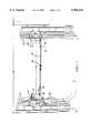
- FIG. 1is a top view of a portion of two conventional seat tracks and opposed master and slave lock bars incorporating a preferred embodiment of the cross wire of the invention
- FIG. 2is a sectional view taken along the line 2--2 of FIG. 1 showing the tracks at any possible spacing within the tolerance range, and showing both lock bars closed with the cross wire in its unstretched condition;
- FIG. 3is a view like FIG. 2, but showing both lock bars fully opened with the track spacing at the low end of the tolerance range;
- FIG. 4is a view like FIG. 3, but showing the tracks more widely separated, at the high end of the tolerance range, and showing the slave lock bar closed and the master lock bar closed;
- FIG. 5is a view like FIG. 4, but showing the cross wire after it has lengthened to allow the adjuster mechanism to rotate farther and fully open the master lock bar.
- a vehicle seat adjuster assemblyincludes a pair of conventional parallel sliding tracks, 10 and 12, to which a standard seat frame would be attached for fore and aft sliding adjustment.
- the tracks 10 and 12have a nominal, least separation indicated at Wn, which can vary with normal manufacturing tolerances up to a greatest separation of Wn plus ⁇ . No particular values need be given, but for any vehicle body, the range of expected tolerance variation would be predictable and known.
- the tracks 10 and 12have fixed lower and slidable upper members that are locked together or released by a pair of standard lock bars, a master lock bar indicated generally at 14, and a slave lock bar indicated generally at 16.
- each lock bar 14 and 16The basic operation of each lock bar 14 and 16 is to engage teeth 18 on the lower part of the tracks 10 and 12 in a closed position, or to disengage from the teeth 18 in an open position. Torsion springs 19 and 21 provide a continual closing or return force to each lock bar 14 and 16, creating a force which is predetermined and fairly consistent. Further structural details of the two lock bars 14 and 16 are described below. Lock bars of this general type are well known, and disclosed in co assigned U.S. Pat. No. 4,852,846 issued Aug. 1, 1989 to Weier. In general, the master lock bar 14 is operated directly by an adjuster mechanism, typically a manual twist handle.
- the slave lock bar 16is indirectly opened and closed by a linking cross wire that runs from the master lock bar 14, operating it passively from, and in tandem with, the directly rotated master lock bar 14.
- a standard, fixed length cross wirecannot be sized so as to allow adequate operation of both lock bars over the entire expected tolerance range of track spacing. If the fixed length cross wire is long enough to allow both lock bars 14 and 16 to fully close under the force of their return springs in a vehicle in which tracks 10 and 12 are widely spaced, it can be too long to allow full opening of the slave lock bar 16 with a narrow track spacing.
- the fixed length cross wireis short enough to allow full opening of the slave lock bar 16 with a narrow track spacing, then it can be too short to allow full opening of the master lock bar 14 at a wider track spacing. In short, one size cannot fit all, and there is no obvious solution to that dilemma. Even if a "too short" cross wire were made continuously stretchable, either inherently or with the addition of a continuously stretchable coil spring, it could simply begin to stretch before the slave lock bar 16 was fully open, which would not be a viable solution.
- the inventionprovides a unique cross wire, a preferred embodiment of which is indicated generally at 20, which stretches only when needed, and not continuously. It has an unstretched fixed length indicated at Ln, which is based on considerations described further below.
- the master lock bar 14has a lock bar lever 22, which engages with the teeth 18 of track 10 in the downwardly rotated, fully closed position shown, or disengages when rotated up and open.
- Lock bar lever 22is directly rotated by a central shaft 24 to which it is keyed, and shaft 24 is rotated by a conventional manually operated twist handle, not illustrated.
- a conventional manually operated twist handlenot illustrated.
- coil spring 19quickly and forcefully returns both lock bar lever 22 and the handle to the down, closed position.
- the master lock bar lever 22may also be operated by a so called “easy entry" mechanism independently of manual twist handle, upon forward pivoting of the seat back.
- slave lock bar 16is indirectly operated by the cross wire 20.
- slave lock bar 16has a lock bar lever 26 that is essentially the mirror image of the opposed master lock bar lever 22, and which engages and disengages with the teeth 18 of track 12 in the same way.
- slave lock bar lever 26freely pivots on a central shaft 28, rather than being keyed thereto.
- Slave lock bar lever 26also has a torsion return spring 21 which, when fully opened, provides a predictable return force, in this case, about 37 Newtons. It requires much less force, of course, only about 7 Newtons, to begin to rotate the slave lock bar lever 26 up from the fully closed position shown.
- Cross wire 20has identical "solid" (but hooked) ends 30 that attach to each lock bar lever 22 and 26, in either direction.
- the center of cross wire 20is not a simple straight wire, however, but an integral, coil spring 32, which is twisted with a preload or pretension that keeps its coils tightly abutted with one another. Therefore, coil spring 32 has a fixed length and is effectively "solid", as is cross wire 20 as a whole, under normal operation.
- the preload in coil spring 32is set to be substantially equal to, or just slightly less than, the fully open spring return force for the slave lock bar 16. This preload, combined with a specifically determined initial length of cross wire 20 (described next), allows the cross wire 20 to operate successfully over the entire spacing tolerance range of the tracks 10 and 12.
- the tracks 10 and 12are illustrated as being spaced apart by any value within the full possible tolerance range, high, low, or in between.
- the cross wire 20 nominal length Lnis long enough to assure that the slave lock bar lever 26 is held fully closed by its return spring, and not held partially open by the cross wire 20, at every possible track separation.
- cross wire 20must in turn be long enough to assure that when the tracks 10 and 12 are spaced apart at or near the high end of the tolerance range, that is, at W plus ⁇ , it is not under enough tension to pull slave lock bar lever 26 partially up.
- cross wire 20in fact may be long enough to be somewhat relaxed when the tracks 10 and 12 are spaced at the low end of the tolerance range, the so called “narrow build” condition (although it is unlikely that it would be so long as to be visibly relaxed or buckled).
- narrow buildthe cross wire 20 must still be short enough to assure that, when the master lock bar lever 22 is rotated fully up and open, the slave lock bar lever 26 follows suit, and does not lag behind. In actual fact, what the designer does to assure successful and complete “narrow build” opening of the slave lock bar 14 is not to assure that the cross wire 20 is "also short enough”.
- the designerassures that the master lock bar lever 22 has enough lever arm and enough "throw” (enough rotation of the twist handle and keyed shaft 24) to open quickly enough and far enough to pull the slave lock bar lever 26 open as the master lock bar 22 opens. Therefore, relatively speaking, the cross wire is "long enough" for wide build closing, and “short enough” for narrow build opening, even though it has only one, fixed or solid length. However, as seen in FIG. 4, what a cross wire having such a fixed length cannot do is assure successful wide build opening. Thus, as seen in FIG. 4, at wide build, a cross wire like 20 with a truly fixed length of Ln can pull the slave lock bar lever 26 fully open before the handle and shaft 24 have rotated enough to fully open the master lock bar lever 22. This is where the dilemma noted above shows up.
- the cross wire 20operates to allow successful wide build opening, by stretching slightly, but only when needed, so as not to jeopardize operation under any other conditions.
- the operator of the seat adjusterwould sense that the seat tracks 10 and 12 were not both fully unlatched, as indicated by an inability to scoot the seat frame back and forth.
- the operatorwould rotate the twist handle and the keyed shaft 24 farther at that point.
- the operatorwould not know or care, of course, that the slave lock bar 16 was already fully open, or that the cross wire 20 had reached the limit of its solid length.
- the return spring of the fully rotated slave lock bar lever 26is applying its full hold open force and tension to the cross wire 20, thereby at least equaling, or even beginning to exceed, the preload threshold of the coil spring 32.
- Thisallows the coil spring 32 to stretch, allowing the cross wire 20 to effectively lengthen as well. Consequently, the additional rotation that the operator will naturally apply to the twist handle and shaft 24 will translate into additional rotation of the master lock bar lever 22, allowing it to disengage from the teeth 18 of track 10, but will not translate into overstressing an already bottomed out, solid cross wire.
- the coil spring 32retracts, cross wire 20 returns to its initial, solid length, and both lock bar levers 22 and 26 rotate fully closed under the force of their respective return springs.
- the cross wire 20 of the inventionoperates like a conventional, fixed length cross wire to allow full closing at any track spacing all the way to the upper end of the tolerance range (FIG. 2). It also allows full opening at the low end of the tolerance range (FIG. 3), but can effectively lengthen at the point, but only at the point, that it becomes necessary (FIG. 4) to allow stress free full opening at wide build (FIG. 5). Variations in the embodiment disclosed could be made. Any central preload means that held the two ends of the cross wire at the fixed length Ln up to the point when the preload threshold was exceeded would work. This could conceivably be a structure other than a tensioned coil spring like 32.
- cross wire 20 with its integral coil spring 32offers the simplest embodiment. Therefore, it will be understood that it is not intended to limit the invention to just the embodiment disclosed.
Landscapes
- Engineering & Computer Science (AREA)
- Aviation & Aerospace Engineering (AREA)
- Transportation (AREA)
- Mechanical Engineering (AREA)
- Seats For Vehicles (AREA)
Abstract
Description
Claims (3)
Priority Applications (1)
| Application Number | Priority Date | Filing Date | Title |
|---|---|---|---|
| US08/816,753US5964442A (en) | 1997-03-03 | 1997-03-03 | Vehicle seat adjuster with self compensating cross wire length |
Applications Claiming Priority (1)
| Application Number | Priority Date | Filing Date | Title |
|---|---|---|---|
| US08/816,753US5964442A (en) | 1997-03-03 | 1997-03-03 | Vehicle seat adjuster with self compensating cross wire length |
Publications (1)
| Publication Number | Publication Date |
|---|---|
| US5964442Atrue US5964442A (en) | 1999-10-12 |
Family
ID=25221522
Family Applications (1)
| Application Number | Title | Priority Date | Filing Date |
|---|---|---|---|
| US08/816,753Expired - Fee RelatedUS5964442A (en) | 1997-03-03 | 1997-03-03 | Vehicle seat adjuster with self compensating cross wire length |
Country Status (1)
| Country | Link |
|---|---|
| US (1) | US5964442A (en) |
Cited By (29)
| Publication number | Priority date | Publication date | Assignee | Title |
|---|---|---|---|---|
| WO2002014102A1 (en)* | 2000-08-16 | 2002-02-21 | Keiper Gmbh & Co. | Longitudinal adjustment device for vehicle seats |
| US6457775B2 (en)* | 2000-01-18 | 2002-10-01 | Faurecia Sieges D'automobile S.A. | Base for a vehicle seat and seat including such a base |
| US20070120407A1 (en)* | 2005-11-29 | 2007-05-31 | Aisin Seiki Kabushiki Kaisha | Vehicle door opening/closing device |
| US7226130B2 (en) | 2002-09-12 | 2007-06-05 | Steelcase Development Corporation | Seating with comfort surface |
| CN103298648A (en)* | 2010-12-30 | 2013-09-11 | C.劳勃.汉默斯坦两合有限公司 | Longitudinal adjustment device for a motor vehicle seat, comprising two pairs of rails |
| US10562414B2 (en) | 2018-05-04 | 2020-02-18 | Lear Corporation | Track assembly |
| US10855037B2 (en) | 2018-12-17 | 2020-12-01 | Lear Corporation | Support assembly with a support member and a track assembly |
| US10882420B2 (en) | 2019-03-08 | 2021-01-05 | Lear Corporation | Track assembly |
| US10906431B2 (en) | 2018-05-04 | 2021-02-02 | Lear Corporation | Track assembly |
| US10926667B2 (en) | 2018-05-04 | 2021-02-23 | Lear Corporation | Track assembly |
| US10950977B2 (en) | 2018-12-18 | 2021-03-16 | Lear Corporation | Track assembly for a vehicle component |
| US11040639B2 (en) | 2018-05-04 | 2021-06-22 | Lear Corporation | Track assembly |
| US11040638B2 (en) | 2018-05-04 | 2021-06-22 | Lear Corporation | Track assembly |
| US11040653B2 (en) | 2019-02-25 | 2021-06-22 | Lear Corporation | Track assembly |
| US11117538B2 (en) | 2018-12-17 | 2021-09-14 | Lear Corporation | Electrical assembly |
| US11225201B2 (en) | 2018-12-10 | 2022-01-18 | Lear Corporation | Track assembly |
| US11299075B2 (en) | 2019-03-06 | 2022-04-12 | Lear Corporation | Electrical assembly |
| US11323114B2 (en) | 2019-10-04 | 2022-05-03 | Lear Corporation | Electrical system |
| US11358497B2 (en) | 2018-05-04 | 2022-06-14 | Lear Corporation | Track system having a rolling member |
| US11440482B2 (en) | 2018-12-10 | 2022-09-13 | Lear Corporation | Track assembly |
| US11463083B2 (en) | 2019-10-04 | 2022-10-04 | Lear Corporation | Electrical system |
| US11506272B2 (en) | 2020-02-21 | 2022-11-22 | Lear Corporation | Track system with a support member |
| US11505141B2 (en) | 2020-10-23 | 2022-11-22 | Lear Corporation | Electrical system with track assembly and support assembly |
| US11613220B2 (en) | 2018-12-17 | 2023-03-28 | Lear Corporation | Electrical assembly |
| US11634101B2 (en) | 2019-10-04 | 2023-04-25 | Lear Corporation | Removable component system |
| US11807142B2 (en) | 2019-03-06 | 2023-11-07 | Lear Corporation | Electrical track assembly |
| US11975665B2 (en) | 2019-02-20 | 2024-05-07 | Lear Corporation | Electrical assembly |
| US12233756B2 (en) | 2018-05-04 | 2025-02-25 | Lear Corporation | Track system with a support member |
| US12253156B2 (en) | 2020-02-21 | 2025-03-18 | Lear Corporation | Track system with a support member |
Citations (9)
| Publication number | Priority date | Publication date | Assignee | Title |
|---|---|---|---|---|
| US3469812A (en)* | 1967-02-09 | 1969-09-30 | Howell Ind Inc | Adjustable vehicle seat mounting |
| US3811726A (en)* | 1971-07-10 | 1974-05-21 | Nissan Motor | Movable seat for a motor vehicle |
| US3940182A (en)* | 1973-08-31 | 1976-02-24 | Nissan Motor Co., Ltd. | Seat position control mechanism having a position memory element |
| US4101169A (en)* | 1976-02-27 | 1978-07-18 | Nissan Motor Company, Limited | Adjustable seat for a motor vehicle |
| US4449752A (en)* | 1979-03-06 | 1984-05-22 | Toyota Jidosha Kogyo Kabushiki Kaisha | Vehicle seat position control mechanism with neutral memory |
| US4629254A (en)* | 1984-04-18 | 1986-12-16 | General Motors Corporation | Motor vehicle seat |
| US4852846A (en)* | 1987-09-04 | 1989-08-01 | General Motors Corporation | Method and apparatus of a conventional fore and aft vehicle seat adjuster convertible into an easy entry seat adjuster slide |
| US4927110A (en)* | 1988-07-25 | 1990-05-22 | Daihatsu Motor Co., Ltd. | Slide locking device for a car seat |
| US4958799A (en)* | 1989-12-18 | 1990-09-25 | Chrysler Corporation | Seat track latch anti-rattle release wire |
- 1997
- 1997-03-03USUS08/816,753patent/US5964442A/ennot_activeExpired - Fee Related
Patent Citations (9)
| Publication number | Priority date | Publication date | Assignee | Title |
|---|---|---|---|---|
| US3469812A (en)* | 1967-02-09 | 1969-09-30 | Howell Ind Inc | Adjustable vehicle seat mounting |
| US3811726A (en)* | 1971-07-10 | 1974-05-21 | Nissan Motor | Movable seat for a motor vehicle |
| US3940182A (en)* | 1973-08-31 | 1976-02-24 | Nissan Motor Co., Ltd. | Seat position control mechanism having a position memory element |
| US4101169A (en)* | 1976-02-27 | 1978-07-18 | Nissan Motor Company, Limited | Adjustable seat for a motor vehicle |
| US4449752A (en)* | 1979-03-06 | 1984-05-22 | Toyota Jidosha Kogyo Kabushiki Kaisha | Vehicle seat position control mechanism with neutral memory |
| US4629254A (en)* | 1984-04-18 | 1986-12-16 | General Motors Corporation | Motor vehicle seat |
| US4852846A (en)* | 1987-09-04 | 1989-08-01 | General Motors Corporation | Method and apparatus of a conventional fore and aft vehicle seat adjuster convertible into an easy entry seat adjuster slide |
| US4927110A (en)* | 1988-07-25 | 1990-05-22 | Daihatsu Motor Co., Ltd. | Slide locking device for a car seat |
| US4958799A (en)* | 1989-12-18 | 1990-09-25 | Chrysler Corporation | Seat track latch anti-rattle release wire |
Cited By (46)
| Publication number | Priority date | Publication date | Assignee | Title |
|---|---|---|---|---|
| US6457775B2 (en)* | 2000-01-18 | 2002-10-01 | Faurecia Sieges D'automobile S.A. | Base for a vehicle seat and seat including such a base |
| WO2002014102A1 (en)* | 2000-08-16 | 2002-02-21 | Keiper Gmbh & Co. | Longitudinal adjustment device for vehicle seats |
| US6695275B2 (en)* | 2000-08-16 | 2004-02-24 | Deiper Gmbh & Co. | Longitudinal adjustment device for vehicle seats |
| US7226130B2 (en) | 2002-09-12 | 2007-06-05 | Steelcase Development Corporation | Seating with comfort surface |
| US7360835B2 (en) | 2002-09-12 | 2008-04-22 | Steelcase Inc. | Seating with comfort surface |
| US20070120407A1 (en)* | 2005-11-29 | 2007-05-31 | Aisin Seiki Kabushiki Kaisha | Vehicle door opening/closing device |
| US7588293B2 (en)* | 2005-11-29 | 2009-09-15 | Aisin Seiki Kabushiki Kaisha | Vehicle walk-in device |
| CN103298648A (en)* | 2010-12-30 | 2013-09-11 | C.劳勃.汉默斯坦两合有限公司 | Longitudinal adjustment device for a motor vehicle seat, comprising two pairs of rails |
| US20130320179A1 (en)* | 2010-12-30 | 2013-12-05 | C. Rob. Hammerstein Gmbh & Co. Kg | Longitudinal adjustment device for a motor vehicle seat, comprising two pairs of rails |
| CN103298648B (en)* | 2010-12-30 | 2016-04-13 | C.劳勃.汉默斯坦两合有限公司 | Be suitable for the longitudinal adjustment apparatus comprising two pairs of guide rails of automobile seat |
| US9676298B2 (en)* | 2010-12-30 | 2017-06-13 | C. Rob. Hammerstein Gmbh & Co. Kg | Longitudinal adjustment device for a motor vehicle seat, comprising two pairs of rails |
| US11040638B2 (en) | 2018-05-04 | 2021-06-22 | Lear Corporation | Track assembly |
| US11040639B2 (en) | 2018-05-04 | 2021-06-22 | Lear Corporation | Track assembly |
| US10850645B2 (en) | 2018-05-04 | 2020-12-01 | Lear Corporation | Track assembly |
| US10850644B2 (en) | 2018-05-04 | 2020-12-01 | Lear Corporation | Support assembly with cam assembly |
| US10562414B2 (en) | 2018-05-04 | 2020-02-18 | Lear Corporation | Track assembly |
| US12233756B2 (en) | 2018-05-04 | 2025-02-25 | Lear Corporation | Track system with a support member |
| US10889208B2 (en) | 2018-05-04 | 2021-01-12 | Lear Corporation | Track assembly |
| US10906431B2 (en) | 2018-05-04 | 2021-02-02 | Lear Corporation | Track assembly |
| US10926667B2 (en) | 2018-05-04 | 2021-02-23 | Lear Corporation | Track assembly |
| US10759308B2 (en) | 2018-05-04 | 2020-09-01 | Lear Corporation | Support assembly |
| US11358497B2 (en) | 2018-05-04 | 2022-06-14 | Lear Corporation | Track system having a rolling member |
| US11225201B2 (en) | 2018-12-10 | 2022-01-18 | Lear Corporation | Track assembly |
| US11440482B2 (en) | 2018-12-10 | 2022-09-13 | Lear Corporation | Track assembly |
| US10855037B2 (en) | 2018-12-17 | 2020-12-01 | Lear Corporation | Support assembly with a support member and a track assembly |
| US11613220B2 (en) | 2018-12-17 | 2023-03-28 | Lear Corporation | Electrical assembly |
| US11117538B2 (en) | 2018-12-17 | 2021-09-14 | Lear Corporation | Electrical assembly |
| US10950977B2 (en) | 2018-12-18 | 2021-03-16 | Lear Corporation | Track assembly for a vehicle component |
| US11975665B2 (en) | 2019-02-20 | 2024-05-07 | Lear Corporation | Electrical assembly |
| US11040653B2 (en) | 2019-02-25 | 2021-06-22 | Lear Corporation | Track assembly |
| US11299075B2 (en) | 2019-03-06 | 2022-04-12 | Lear Corporation | Electrical assembly |
| US12401174B2 (en) | 2019-03-06 | 2025-08-26 | Lear Corporation | Electrical track assembly |
| US11807142B2 (en) | 2019-03-06 | 2023-11-07 | Lear Corporation | Electrical track assembly |
| US10882420B2 (en) | 2019-03-08 | 2021-01-05 | Lear Corporation | Track assembly |
| US11463083B2 (en) | 2019-10-04 | 2022-10-04 | Lear Corporation | Electrical system |
| US11634101B2 (en) | 2019-10-04 | 2023-04-25 | Lear Corporation | Removable component system |
| US11323114B2 (en) | 2019-10-04 | 2022-05-03 | Lear Corporation | Electrical system |
| US12044301B2 (en) | 2020-02-21 | 2024-07-23 | Lear Corporation | Track system with a support member |
| US11906028B2 (en) | 2020-02-21 | 2024-02-20 | Lear Corporation | Track system with a support member |
| US11835119B2 (en) | 2020-02-21 | 2023-12-05 | Lear Corporation | Track system with a support member |
| US12055205B2 (en) | 2020-02-21 | 2024-08-06 | Lear Corporation | Track system with a support member |
| US12181033B2 (en) | 2020-02-21 | 2024-12-31 | Lear Corporation | Track system with a support member |
| US12253156B2 (en) | 2020-02-21 | 2025-03-18 | Lear Corporation | Track system with a support member |
| US11506272B2 (en) | 2020-02-21 | 2022-11-22 | Lear Corporation | Track system with a support member |
| US12012056B2 (en) | 2020-10-23 | 2024-06-18 | Lear Corporation | Electrical system with track assembly and support assembly |
| US11505141B2 (en) | 2020-10-23 | 2022-11-22 | Lear Corporation | Electrical system with track assembly and support assembly |
Similar Documents
| Publication | Publication Date | Title |
|---|---|---|
| US5964442A (en) | Vehicle seat adjuster with self compensating cross wire length | |
| CA2952128C (en) | Quick adjust power adjuster with split nut for automotive seat | |
| US5788325A (en) | Locking mechanism for a vehicle seat, and a seat including such a mechanism | |
| US6631952B1 (en) | Automobile seat | |
| US20030122412A1 (en) | Seat device | |
| CA2165436A1 (en) | Device for adjusting a flexible supporting element of a back-rest | |
| US7021696B2 (en) | Convertible top latch | |
| US10232745B2 (en) | Actuating module for a vehicle seat | |
| EP2352660B1 (en) | Car seat with a clip arrangement | |
| US9944201B2 (en) | Quick adjust power adjuster with tubular lead screw | |
| CA2184803A1 (en) | Simplified linear recliner | |
| WO2006020313A3 (en) | Vehicule seat back recliner and assembly | |
| DE3934171A1 (en) | VEHICLE SEAT WITH BACKREST INCLINATION DEVICE | |
| US6688190B2 (en) | Manual lever drive for adjusting devices on seats, in particular, motor vehicles seats | |
| US7390062B2 (en) | Seat having cushion height and recline adjustment mechanisms | |
| JPH072127B2 (en) | Continuously adjustable hinge | |
| US6761408B2 (en) | Linear recliner having an internal cam spring | |
| US4842234A (en) | Method and apparatus for linear braking and chair with linear brake | |
| DE112005001156T5 (en) | Furniture mechanism with spring rocker | |
| US7300108B2 (en) | Automobile seat with adjustable-height seat pan having a seat belt attachment point | |
| DE102004051873B4 (en) | Automotive seat | |
| EP0904223B1 (en) | Regulator for automatically adjusting the length of an actuating link | |
| CN115303148A (en) | Vehicle Seat Crash Protectors and Vehicle Seats | |
| EP1241366B1 (en) | Device for compensating automatically variations in the length of push-pull cable | |
| US10736428B2 (en) | Vehicle seat |
Legal Events
| Date | Code | Title | Description |
|---|---|---|---|
| AS | Assignment | Owner name:GENERAL MOTORS CORPORATION, MICHIGAN Free format text:ASSIGNMENT OF ASSIGNORS INTEREST;ASSIGNORS:WINGBLAD, GLEN DANIEL;PARKO, GARY PAUL;ADAMS, ROBERT PAUL;REEL/FRAME:008457/0201 Effective date:19970214 | |
| AS | Assignment | Owner name:LEAR CORPORATION, MICHIGAN Free format text:ASSIGNMENT OF ASSIGNORS INTEREST;ASSIGNOR:GENERAL MOTORS CORPORATION;REEL/FRAME:009453/0621 Effective date:19980831 | |
| FEPP | Fee payment procedure | Free format text:PAYOR NUMBER ASSIGNED (ORIGINAL EVENT CODE: ASPN); ENTITY STATUS OF PATENT OWNER: LARGE ENTITY Free format text:PAYER NUMBER DE-ASSIGNED (ORIGINAL EVENT CODE: RMPN); ENTITY STATUS OF PATENT OWNER: LARGE ENTITY | |
| FPAY | Fee payment | Year of fee payment:4 | |
| AS | Assignment | Owner name:JPMORGAN CHASE BANK, N.A., AS GENERAL ADMINISTRATI Free format text:SECURITY AGREEMENT;ASSIGNOR:LEAR CORPORATION;REEL/FRAME:017858/0719 Effective date:20060425 | |
| REMI | Maintenance fee reminder mailed | ||
| LAPS | Lapse for failure to pay maintenance fees | ||
| STCH | Information on status: patent discontinuation | Free format text:PATENT EXPIRED DUE TO NONPAYMENT OF MAINTENANCE FEES UNDER 37 CFR 1.362 | |
| FP | Lapsed due to failure to pay maintenance fee | Effective date:20071012 | |
| AS | Assignment | Owner name:LEAR CORPORATION, MICHIGAN Free format text:RELEASE BY SECURED PARTY;ASSIGNOR:JPMORGAN CHASE BANK, N.A.;REEL/FRAME:032722/0553 Effective date:20100830 | |
| AS | Assignment | Owner name:LEAR CORPORATION, MICHIGAN Free format text:RELEASE BY SECURED PARTY;ASSIGNOR:JPMORGAN CHASE BANK, N.A., AS AGENT;REEL/FRAME:037731/0918 Effective date:20160104 |