US5964252A - Adhesive closure system with an abridged release liner - Google Patents
Adhesive closure system with an abridged release linerDownload PDFInfo
- Publication number
- US5964252A US5964252AUS08/993,587US99358797AUS5964252AUS 5964252 AUS5964252 AUS 5964252AUS 99358797 AUS99358797 AUS 99358797AUS 5964252 AUS5964252 AUS 5964252A
- Authority
- US
- United States
- Prior art keywords
- adhesive layer
- area
- release liner
- insulation sleeve
- pipe insulation
- Prior art date
- Legal status (The legal status is an assumption and is not a legal conclusion. Google has not performed a legal analysis and makes no representation as to the accuracy of the status listed.)
- Expired - Lifetime
Links
- 239000000853adhesiveSubstances0.000titleclaimsabstractdescription54
- 230000001070adhesive effectEffects0.000titleclaimsabstractdescription54
- 238000009413insulationMethods0.000claimsabstractdescription71
- 239000012790adhesive layerSubstances0.000claimsabstractdescription65
- 239000004820Pressure-sensitive adhesiveSubstances0.000claimsdescription22
- 239000010410layerSubstances0.000claimsdescription12
- 238000007789sealingMethods0.000claimsdescription7
- 239000011810insulating materialSubstances0.000claimsdescription6
- 238000000034methodMethods0.000claimsdescription5
- 230000001681protective effectEffects0.000claimsdescription5
- 239000002356single layerSubstances0.000description5
- 238000004519manufacturing processMethods0.000description4
- 238000003860storageMethods0.000description4
- 239000003365glass fiberSubstances0.000description3
- 238000009434installationMethods0.000description3
- 239000000463materialSubstances0.000description3
- 239000007787solidSubstances0.000description2
- -1vinyl nitrileChemical class0.000description2
- 229920002554vinyl polymerPolymers0.000description2
- 229910001018Cast ironInorganic materials0.000description1
- RYGMFSIKBFXOCR-UHFFFAOYSA-NCopperChemical compound[Cu]RYGMFSIKBFXOCR-UHFFFAOYSA-N0.000description1
- 229910052802copperInorganic materials0.000description1
- 239000010949copperSubstances0.000description1
- 238000005520cutting processMethods0.000description1
- 239000006263elastomeric foamSubstances0.000description1
- 239000006260foamSubstances0.000description1
- 239000011888foilSubstances0.000description1
- 238000002955isolationMethods0.000description1
- 239000002655kraft paperSubstances0.000description1
- 239000007788liquidSubstances0.000description1
- 239000000123paperSubstances0.000description1
- 239000011101paper laminateSubstances0.000description1
- 230000000704physical effectEffects0.000description1
- 229920003023plasticPolymers0.000description1
- 229920000642polymerPolymers0.000description1
- 229920001296polysiloxanePolymers0.000description1
- 230000002028prematureEffects0.000description1
- 239000011253protective coatingSubstances0.000description1
- 238000005728strengtheningMethods0.000description1
- 229920001187thermosetting polymerPolymers0.000description1
- 239000011800void materialSubstances0.000description1
Images

Classifications
- F—MECHANICAL ENGINEERING; LIGHTING; HEATING; WEAPONS; BLASTING
- F16—ENGINEERING ELEMENTS AND UNITS; GENERAL MEASURES FOR PRODUCING AND MAINTAINING EFFECTIVE FUNCTIONING OF MACHINES OR INSTALLATIONS; THERMAL INSULATION IN GENERAL
- F16L—PIPES; JOINTS OR FITTINGS FOR PIPES; SUPPORTS FOR PIPES, CABLES OR PROTECTIVE TUBING; MEANS FOR THERMAL INSULATION IN GENERAL
- F16L59/00—Thermal insulation in general
- F16L59/02—Shape or form of insulating materials, with or without coverings integral with the insulating materials
- F16L59/021—Shape or form of insulating materials, with or without coverings integral with the insulating materials comprising a single piece or sleeve, e.g. split sleeves; consisting of two half sleeves; comprising more than two segments
- F16L59/022—Shape or form of insulating materials, with or without coverings integral with the insulating materials comprising a single piece or sleeve, e.g. split sleeves; consisting of two half sleeves; comprising more than two segments with a single slit
- F—MECHANICAL ENGINEERING; LIGHTING; HEATING; WEAPONS; BLASTING
- F16—ENGINEERING ELEMENTS AND UNITS; GENERAL MEASURES FOR PRODUCING AND MAINTAINING EFFECTIVE FUNCTIONING OF MACHINES OR INSTALLATIONS; THERMAL INSULATION IN GENERAL
- F16L—PIPES; JOINTS OR FITTINGS FOR PIPES; SUPPORTS FOR PIPES, CABLES OR PROTECTIVE TUBING; MEANS FOR THERMAL INSULATION IN GENERAL
- F16L59/00—Thermal insulation in general
- F16L59/10—Bandages or covers for the protection of the insulation, e.g. against the influence of the environment or against mechanical damage
- Y—GENERAL TAGGING OF NEW TECHNOLOGICAL DEVELOPMENTS; GENERAL TAGGING OF CROSS-SECTIONAL TECHNOLOGIES SPANNING OVER SEVERAL SECTIONS OF THE IPC; TECHNICAL SUBJECTS COVERED BY FORMER USPC CROSS-REFERENCE ART COLLECTIONS [XRACs] AND DIGESTS
- Y10—TECHNICAL SUBJECTS COVERED BY FORMER USPC
- Y10S—TECHNICAL SUBJECTS COVERED BY FORMER USPC CROSS-REFERENCE ART COLLECTIONS [XRACs] AND DIGESTS
- Y10S138/00—Pipes and tubular conduits
- Y10S138/01—Adhesive
- Y—GENERAL TAGGING OF NEW TECHNOLOGICAL DEVELOPMENTS; GENERAL TAGGING OF CROSS-SECTIONAL TECHNOLOGIES SPANNING OVER SEVERAL SECTIONS OF THE IPC; TECHNICAL SUBJECTS COVERED BY FORMER USPC CROSS-REFERENCE ART COLLECTIONS [XRACs] AND DIGESTS
- Y10—TECHNICAL SUBJECTS COVERED BY FORMER USPC
- Y10T—TECHNICAL SUBJECTS COVERED BY FORMER US CLASSIFICATION
- Y10T428/00—Stock material or miscellaneous articles
- Y10T428/14—Layer or component removable to expose adhesive
Definitions
- the present inventionrelates to an adhesive closure system. More specifically this invention relates to an improved adhesive closure system with an abridged release liner for closing the slit in pipe insulation sleeves.
- pressure sensitive adhesiverefers to an adhesive that is tacky at ambient or room temperatures. Pressure sensitive adhesives are often used as the adhesive means in various closure systems. The pressure sensitive adhesive on a closure system must be covered with a release liner during shipping or a storage to prevent a premature permanent bond from occurring. The release liner completely isolates the intended exposed area of the adhesive. This complete isolation of the adhesive is not always desirable.
- a particular application of this type of temporary to permanent adhesive closure systemis in the area of pipe insulation sleeves.
- Pipes which are used in dwellings and commercial buildingsare often covered with an insulation sleeve or wrap.
- the insulation sleevesare typically installed for improved energy efficiency or safety.
- the pipesmay be made of copper, plastic, cast iron, or other like materials.
- the insulation sleeve or wrapis generally a cylindrically shaped tubular section having a centrally disposed channel along its longitudinal axis to receive the pipe.
- the insulation sleevemay be constructed of a flexible elastomeric foam such as vinyl nitrile, or various other insulating materials such as a glass fiber layer with a protective overcoating.
- Each sectionhas a slit that extends radially from the inside diameter of the tube to its outer surface, and longitudinally along the entire length of the sleeve.
- This slitherein referred to as the access slit, affords an opening, or access for the pipe to enter the sleeve so as to reside within the central channel.
- the insulation sleevewill come in 6 to 8 foot lengths with internal diameters ranging from 1 to 8 inches and external diameters ranging from 2 to 10 inches.
- the tubular insulationis cut to length and installed around the pipe by means of the longitudinal access slit. Once the sleeve is in place, the opposite walls of the access slit are brought together and sealed.
- An alternate method of closurecomprises a longitudinally extending flap, herein referred to as a closure flap, on the outer surface of one side of the access slit, the closure flap incorporates a pressure sensitive adhesive on the inner side of the flap. The flap is pressed into engagement with the outer surface of the other side of the access slit, thereby forming the adhesive bond.
- Adhesiveis typically applied during manufacture of the insulation sleeve and a solid release liner is applied to the adhesive. It is known to use a solid release liner that completely covers and isolates the exposed side of the adhesive to allow the insulation sleeve to be shipped and installed before a permanent bond is achieved. Alternately, the adhesive can be applied during the installation of the insulation sleeve, by the installer. Both of these methods require the insulation sleeve to be shipped with the access slit in an unbonded or open position. An insulation sleeve shipped with the access slit in this open position, is less rigid than if the access slit were bonded in the closed position.
- the open or unbonded insulation sleeveis less rigid than a closed or unified sleeve, the open sleeve may permanently deform from its own weight and the weight of the sleeves stored above it. This deformation causes numerous problems including sleeves that do not fit in the intended pipe, and internal stresses that occur when the deformed sleeve is placed on the pipe, causing the adhesive joint to prematurely fail.
- the present inventiondiscloses an improved adhesive closure system.
- a preferred embodiment of the inventiondiscloses an improved adhesive closure system for pipe insulating sleeves which employs an area or elongated strip or segment of a single layer of pressure sensitive adhesive with an abridged release liner partially covering the adhesive surface.
- "Abridged” as used hereinmeans a release liner which is shortened in length or width, or otherwise abbreviated by cutting away sections thereof, or by perforating or boring holes therethrough.
- the preferred embodimentemploys a release liner that is abridged by means of perforations or holes disposed therein.
- the single layer of pressure sensitive adhesive and the perforated release linerextend the length of the insulating sleeve, along its longitudinal axis.
- One side of the pressure sensitive adhesive stripis affixed to the inner surface of a longitudinally extending closure flap.
- the perforated release lineris removable affixed to the exposed side of the pressure sensitive adhesive on the inner side of the closure flap.
- This closure flapmay be integral with, or affixed to, the outer surface of the pipe insulation sleeve, adjacent and longitudinally parallel to the access slit.
- the amount of percentage of pressure sensitive adhesive exposed by the bridged release liner through apertures or perforationsis sufficient to form a first or temporary bond when the closure flap is pressed into engagement with the outer surface of the pipe insulation sleeve on the opposite side of the access slit.
- the inventorshave identified several instances where an initial temporary bond may be desired during shipping or storage, followed by a permanent bond upon final disposition of the closure system.
- Temporary bondas used herein defines a level of adhesion sufficient to releasably affix the intended elements.
- the amount of adhesive exposed to form the temporary bondmay be any predetermined percentage necessary for the particular application.
- the initial bondmust have the strength to temporarily adhere the surfaces together, but when desired, have the ability to be separated so as to enable the removal of the release liner, thereby exposing the adhesive surface in its entirety, in order that a second, permanent bond can be achieved.
- Permanent bondas used herein defines a level of adhesion at least equal to the temporary bond and sufficient to affix the intended elements in final placement.
- the first, temporary bondunitizes the insulation sleeve, thereby strengthening the sleeve so as to reduce damage and deformation during shipping.
- the closure flapcan be pulled away from the outer surface of the opposite side of the access slit, thereby severing the temporary adhesive bond, thus enabling the insulation sleeve to be installed around a pipe by means of the access slit.
- the perforated release lineris pulled away from the pressure sensitive adhesive strip, thereby exposing the remainder of the adhesive surface. The area of exposed adhesive is then sufficient to achieve a second, permanent bond when the closure flap is pressed into engagement with the outer surface of the insulation sleeve on the opposite side of the access slit.
- first, temporary closurewhen desired a second, permanent closure, using only a single layer of a single adhesive.
- Theseinclude but are not limited to large document envelopes that are often handled, transported and the contents added to or viewed by numerous people in an office environment prior to final mailing. It would be desirable to have a temporary closure system to secure the contents of the envelopes prior to mailing, and upon removal of the abridged release liner, have a permanent adhesive closure suitable for mailing.
- Another applicationcould involve bags or boxes that are being filled with parts on an assembly line.
- a temporary closure to secure the contents between stations on an assembly line, then upon removal of the release linerpermanently close the bag or box for shipping.
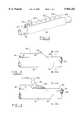
- FIG. 1is a perspective view of a pipe covered with an insulation sleeve that incorporates the present invention as the closure system.
- FIG. 2is a front elevational view showing a partial segment of a pipe insulation sleeve that incorporates a preferred embodiment of the present invention as the closure system.
- FIG. 3is a front elevational view showing a partial segment of a pipe, covered with a partial segment of pipe insulation sleeve that incorporates the preferred embodiment of the present invention as the closure system.
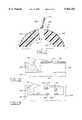
- FIG. 4is an enlarged fragmentary cross sectional view along section line B--B of FIG. 2, showing a cross section of a preferred embodiment of the present invention in place on the closure flap of a pipe insulating sleeve utilizing a first or temporary bond.
- FIG. 5is an enlarged fragmentary cross sectional view along section line C--C of FIG. 3, showing a cross section of a preferred embodiment of the present invention in place on the closure flap of a pipe insulating sleeve, which is installed on a pipe, illustrating the second or permanent bond.
- FIG. 6is an enlarged fragmentary cross sectional view of the present invention in place on a pipe insulation sleeve according to a second embodiment.
- FIG. 7is an enlarged fragmentary cross sectional view of the present invention in place on a pipe insulation sleeve according to a third embodiment.
- FIG. 8is a fragmentary view of an alternate embodiment of the present invention in place on the closure flap of a pipe insulation sleeve.
- FIG. 9is a fragmentary view of an alternate embodiment of the present invention in place on the closure flap of a box, bag or envelope, showing some of the many possible shapes, sizes and locations of perforations in the release liner.
- FIG. 1illustrates a first preferred embodiment of the present invention used as the closure system for a pipe insulation sleeve.
- Insulation sleeve 10known in prior art to be a longitudinally extending cylindrical tube, with a radial access slit 12, which extends from the inner surface of the sleeve to the outer surface, and longitudinally along the entire length of the sleeve.
- Sleeve 10may be constructed of a flexible foam elastomeric such as vinyl nitrile or various other insulating materials known in the art such as a glass fiber layer wrapped in a protective coating. Access slit 12, allows insulation sleeve 10, to be installed around pipe 8.
- Closure flap 20is integral with or affixed to the outer surface of insulation sleeve 10, adjacent and longitudinally parallel to access slit 12.
- the preferred adhesive system of the present inventionis installed on closure flap 20, of pipe insulation sleeve 10.
- the present inventioncomprises a single layer or strip of pressure sensitive adhesive 40, one side of which is affixed to the inner surface of closure flap 20.
- the adhesive layer or stripcan be applied as a liquid or a film during the manufacture of the insulating sleeve and closure flap.
- adhesive layer 40extends substantially the entire length of closure flap 20, along its longitudinal axis.
- the exposed side of adhesive layer 40is covered by a release liner 30.
- Release liner 30is a strip or segment of paper or paper laminate coated with a non-stick film such as silicone, or a polymer strip or segment with non-stick properties or similarly coated, which is removably attached to adhesive layer 40, in a manner well understood by one skilled in the art.
- Release liner 30,has perforations 50, spaced at intervals along its length.
- perforationmeans a hole, slit, cut out section or aperture with a closed perimeter or with a perimeter that intersects the perimeter of the material in which the perforation is made.
- the preferred embodimentincorporates a release liner 30, that preferably has the same perimeter shape as the adhesive layer, and its perimeter length is equal to or greater than the perimeter length of the adhesive. The later would afford a pull tab for ease of removal.
- the adhesiveis completely covered by the release liner except for areas exposed by perforations 50.
- the percentage of initially exposed adhesiveshould be in the range of 0% ⁇ >50%, but preferably in the range of 5% ⁇ >35%.
- An alternate embodimentemploys the size, shape and contour of the perimeter of release liner 30 to expose the desired percentage of adhesive layer 40. Perforations 50, allow a predetermined amount or percentage of adhesive layer 40, to be exposed there through.
- perforations 50are shown circular in shape, but may be any other conic section or portion thereof or polygonal and of a size that will allow the desired percentage of adhesive layer 40, to be exposed.
- Perforations 50may be one or more in quantity, and be spaced at any interval and located at any position along release liner 30, without departing from the spirit of the invention.
- the pipe insulating sleeve 10employs the preferred embodiment of the present invention on closure flap 20.
- release liner 30, removable attached to pressure sensitive adhesive layer 40the free edge 22, of closure flap 20, has been folded across access slit 12, and the inner surface of closure flap 20, has been pressed into engagement with, and is temporarily bonded to the outer surface of insulating sleeve 10, adjacent to slit 12, at end 16.
- This temporary bondis achieved by a portion of pressure sensitive adhesive layer 40, which is exposed through release liner 30, by means of the void or hole created in release liner 30, by perforation 50.
- FIG. 4shows an enlarged fragmentary cross sectional view of the temporary bond created in FIG. 2, at end 16, of sleeve 10, across section line B--B.
- Free edge 22 of closure flap 20is temporarily bonded to insulating sleeve 10 by means of an area of pressure sensitive adhesive layer 40, being exposed through the perforations in release liner 30.
- a temporary bond as describedwould be employed during shipping and storage of the pipe insulation sleeve, prior to installation on as pipe.
- FIG. 4also shows edge 24, of non-integral closure flap 20, affixed to insulating sleeve 10.
- Joint 60is created during the manufacture of sleeve 10, and is used to locate sleeve closure flap 20 on sleeve 10.
- Joint 60may be an adhesive, a thermal bond or any other essentially permanent method of attachment known in the art, and is intended to permanently anchor the closure system in correct orientation relative to slit 12.
- release liner 30has been removed from pressure sensitive adhesive layer 40, on the inside surface of closure flap 20, at end 16, of sleeve 10. Free edge 22 of closure flap 20, is folded over access slit 12, and the full surface area of pressure sensitive adhesive 40, is engaged with the outer surface of sleeve 10 adjacent to access slit 12. By engaging the full exposed surface area of pressure sensitive adhesive layer 40, a permanent bond is achieved.
- FIG. 5shows an enlarged fragmentary cross sectional view of the permanent bond created in FIG. 3, at end 16, of sleeve 10, across section line C--C.
- Pressure sensitive adhesive layer 40is in full contact with closure flap 20 and sleeve 10, thereby creating a permanent bond between them.
- a permanent bond as describedwould be employed when the pipe insulation sleeve is in a final position, installed around a pipe.
- FIG. 5also shows edge 24 of closure flap 20, affixed to insulation sleeve 10.
- Bond 60may be an adhesive, a thermal bond or any other permanent bond known in the art.
- FIG. 6discloses another embodiment wherein one side of the adhesive layer 40, is affixed to one of the opposed terminal edges of the longitudinal extending radial access slit 12, of insulation sleeve 10.
- Perforated release liner 30is removably affixed to the exposed side of adhesive layer 40.
- a percentage of adhesive layer 40is exposed through release liner 30, through the apertures or holes of perforations 50.
- FIG. 7discloses still another embodiment wherein pipe insulation sleeve 100 is constructed of a glass fiber or other material known in the art to have acceptable physical properties to serve as an insulation.
- a protective covering 110such as a reflective foil or kraft paper is engaged with and covers the exterior surface of insulation sleeve 100.
- a closure flap 120integral with the protective covering 110, extends from the insulation sleeve 100, adjacent to access slit 12.
- One side of adhesive layer 40is affixed to the inner surface of closure flap 120.
- Perforated release liner 30is removably affixed to the exposed side of pressure sensitive adhesive 40. A percentage of adhesive layer 40, is exposed through release liner 30, through the apertures or holes of perforations 50.
- closure flap 120When closure flap 120, is folded across access slit 12, and pressed into sealing engagement with protective cover 110, and adhesive bond if formed.
- the bondmay be temporary if release liner 30 is included in the engagement, or a permanent bond may be achieved if release liner 30 is removed.
- FIG. 8discloses still another embodiment of the present invention.
- One side of adhesive layer 40is affixed to closure flap 20.
- Abridged release liner 30,is removably affixed to the other side of adhesive layer 40.
- the size, shape and placement of abridged release liner 30, in relation to the size and shape of adhesive layer 40,allow a percentage of adhesive layer 40, to be exposed near edge 22, of closure flap 20.
- the percentage of adhesive exposed when abridged release liner 30, is removably affixed to adhesive layer 40is sufficient to achieve a temporary bond between closure flap 20 and the pipe insulating sleeve on which it is affixed.
- a portion of abridged release liner 30,has been peeled away from adhesive layer 40, at end 14, or closure flap 20.
- the amount of adhesive layer 40, exposed when abridged release liner 30 is removedis sufficient to achieve a permanent bond.
- FIG. 9discloses still another embodiment of the present invention that could be used as the closure flap for numerous applications including a bag, box, or envelope.
- One side of adhesive layer 40is affixed to closure flap 20.
- Abridged release liner 30,is removably affixed to the other side of adhesive layer 40.
- a percentage of adhesive layer 40is exposed through release liner 30, through the apertures or holes of perforations 50. Perforations 50 are shown in some of the many possible locations and shapes in which they may occur.
- the percentage of adhesive exposed when abridged release liner 30, is removably affixed to adhesive layer 40is sufficient to achieve a temporary bond between closure flap 20 and the surface on which it is to be affixed.
- a portion of abridged release liner 30,has been peeled away from adhesive layer 40, at end 14, of closure flap 20.
- the amount of adhesive layer 40, exposed when abridged release liner 30 is removedis sufficient to achieve a permanent bond.
Landscapes
- Engineering & Computer Science (AREA)
- General Engineering & Computer Science (AREA)
- Mechanical Engineering (AREA)
- Thermal Insulation (AREA)
- Adhesives Or Adhesive Processes (AREA)
- Lining Or Joining Of Plastics Or The Like (AREA)
- Non-Disconnectible Joints And Screw-Threaded Joints (AREA)
Abstract
Description
Claims (26)
Priority Applications (2)
| Application Number | Priority Date | Filing Date | Title |
|---|---|---|---|
| US08/993,587US5964252A (en) | 1997-12-18 | 1997-12-18 | Adhesive closure system with an abridged release liner |
| CA002256057ACA2256057C (en) | 1997-12-18 | 1998-12-15 | Adhesive closure system with an abridged release liner |
Applications Claiming Priority (1)
| Application Number | Priority Date | Filing Date | Title |
|---|---|---|---|
| US08/993,587US5964252A (en) | 1997-12-18 | 1997-12-18 | Adhesive closure system with an abridged release liner |
Publications (1)
| Publication Number | Publication Date |
|---|---|
| US5964252Atrue US5964252A (en) | 1999-10-12 |
Family
ID=25539729
Family Applications (1)
| Application Number | Title | Priority Date | Filing Date |
|---|---|---|---|
| US08/993,587Expired - LifetimeUS5964252A (en) | 1997-12-18 | 1997-12-18 | Adhesive closure system with an abridged release liner |
Country Status (2)
| Country | Link |
|---|---|
| US (1) | US5964252A (en) |
| CA (1) | CA2256057C (en) |
Cited By (50)
| Publication number | Priority date | Publication date | Assignee | Title |
|---|---|---|---|---|
| USD437723S1 (en) | 1999-01-20 | 2001-02-20 | Lees Tony R | Protective covering for furniture legs |
| US6196272B1 (en)* | 1999-02-12 | 2001-03-06 | Mary Maureen Davis | Modular insulated pipe |
| US6216742B1 (en)* | 1999-02-22 | 2001-04-17 | Totaku Industries, Inc. | Heat insulating hose |
| US6315759B1 (en)* | 1999-12-21 | 2001-11-13 | Travis Peterson | Protective cover for intravenous lines and other elongated members |
| US6341626B1 (en)* | 1998-04-18 | 2002-01-29 | Federal-Mogul Technology Limited | Flexible protective sleeve |
| US6428651B1 (en) | 2000-04-27 | 2002-08-06 | Plastic Technology, Inc. | Method and apparatus for applying adhesives to the edges of a slit tube |
| US20040022983A1 (en)* | 2002-08-01 | 2004-02-05 | Francois Bayzelon | Method and apparatus for manufacturing pressure sensitive adhesive label stocks with printing under adhesive and product produced thereby |
| US20040079431A1 (en)* | 2002-09-04 | 2004-04-29 | Kissell Ronald E. | Pipe blanket to fit a variety of pipe diameters |
| US20040154833A1 (en)* | 2003-02-07 | 2004-08-12 | Ziolkowski Christopher J. | Long range data transmitter for horizontal directional drilling |
| US6783830B2 (en) | 2003-01-23 | 2004-08-31 | Venture Tape Corp | Adhesive tape structure for use with insulation jackets |
| US6843279B1 (en)* | 2003-12-17 | 2005-01-18 | Johns Manville International, Inc. | Jacketed pipe insulation with integral ruler |
| US20050031821A1 (en)* | 2003-08-05 | 2005-02-10 | Clark Kim Marie | Adhesive cord cover |
| US20050115625A1 (en)* | 2003-09-17 | 2005-06-02 | Thermo-Tec | Heat shield |
| US6935379B1 (en)* | 2002-05-08 | 2005-08-30 | Marvin C. Buchanan, Sr. | Prefabricated insulation for HVAC ductwork and other fluid conduits |
| EP1482235A3 (en)* | 2003-05-30 | 2006-04-26 | Johns Manville International, Inc. | Coated fibrous pipe insulation system |
| US20060227585A1 (en)* | 2005-03-24 | 2006-10-12 | Masanori Tomoda | Computer system, disk apparatus and data update control method |
| US20060240209A1 (en)* | 2003-04-25 | 2006-10-26 | Nitto Denko Corporation | Pressure-sensitive adhesive tape or sheet, and method for producing it |
| US20070211966A1 (en)* | 2006-03-08 | 2007-09-13 | Heien Troy A | Multi-compartment trash or recycling bag |
| US20070248817A1 (en)* | 2004-10-26 | 2007-10-25 | Uzin Tyro Ag | Self-Adhesive Film with Air Channels and/or Air Chambers |
| US20070256365A1 (en)* | 2006-04-13 | 2007-11-08 | Petty Charles J | Temporary closure for insulation facing or vapor retarder and method of producing the temporary closure |
| US20100143711A1 (en)* | 2008-12-04 | 2010-06-10 | Nitto Denko Corporation | Double-faced pressure-sensitive adhesive tape |
| EP2226370A1 (en)* | 2009-03-06 | 2010-09-08 | Nitto Denko Corporation | Double-sided pressure-sensitive adhesive tape and method for attaching the same, and release liner |
| US20130122233A1 (en)* | 2000-10-03 | 2013-05-16 | Hideyuki Nojiri | Double eyelid forming tape or string and method of manufacturing the same |
| US20130291464A1 (en)* | 2012-05-04 | 2013-11-07 | Garland Industries, Inc. | Non-welded coping caps and transitions |
| US20140305534A1 (en)* | 2013-04-11 | 2014-10-16 | Aeroflex Usa | Insulation Jacket |
| US20140330227A1 (en) | 2010-03-16 | 2014-11-06 | Kci Licensing, Inc. | Delivery-and-fluid-storage bridges for use with reduced-pressure systems |
| US20150119831A1 (en) | 2013-10-30 | 2015-04-30 | Kci Licensing, Inc. | Condensate absorbing and dissipating system |
| US20150119833A1 (en)* | 2013-10-30 | 2015-04-30 | Kci Licensing, Inc. | Dressing with differentially sized perforations |
| US20150119832A1 (en)* | 2013-10-30 | 2015-04-30 | Kci Licensing, Inc. | Dressing with sealing and retention interface |
| US20150260329A1 (en)* | 2014-03-11 | 2015-09-17 | Christian Bond | Removable and Reusable Insulation Wrap for Pipe, Hoses, and Fixtures |
| US20160072263A1 (en)* | 2011-12-01 | 2016-03-10 | Rockbestos Surprenant Cable Corp. | Perforation Apparatus for Cable Jackets and Related Systems and Methods |
| US9925092B2 (en) | 2013-10-30 | 2018-03-27 | Kci Licensing, Inc. | Absorbent conduit and system |
| US10010656B2 (en) | 2008-03-05 | 2018-07-03 | Kci Licensing, Inc. | Dressing and method for applying reduced pressure to and collecting and storing fluid from a tissue site |
| CN108431481A (en)* | 2015-11-12 | 2018-08-21 | 欧文斯科宁知识产权资产有限公司 | Pipeline insulation assembly |
| US10231547B2 (en)* | 2016-07-29 | 2019-03-19 | Anyplace Concepts Co., Ltd. | Connector for sofa chair frame and sofa chair frame having same |
| US10299605B2 (en) | 2015-10-16 | 2019-05-28 | Anyplace Concepts Co., Ltd. | Sofa chair |
| US10398604B2 (en) | 2014-12-17 | 2019-09-03 | Kci Licensing, Inc. | Dressing with offloading capability |
| US10406266B2 (en) | 2014-05-02 | 2019-09-10 | Kci Licensing, Inc. | Fluid storage devices, systems, and methods |
| US10561534B2 (en) | 2014-06-05 | 2020-02-18 | Kci Licensing, Inc. | Dressing with fluid acquisition and distribution characteristics |
| US10632020B2 (en) | 2014-02-28 | 2020-04-28 | Kci Licensing, Inc. | Hybrid drape having a gel-coated perforated mesh |
| US10842707B2 (en) | 2012-11-16 | 2020-11-24 | Kci Licensing, Inc. | Medical drape with pattern adhesive layers and method of manufacturing same |
| US10940047B2 (en) | 2011-12-16 | 2021-03-09 | Kci Licensing, Inc. | Sealing systems and methods employing a hybrid switchable drape |
| US10946124B2 (en) | 2013-10-28 | 2021-03-16 | Kci Licensing, Inc. | Hybrid sealing tape |
| US10945889B2 (en) | 2011-12-16 | 2021-03-16 | Kci Licensing, Inc. | Releasable medical drapes |
| US10973694B2 (en) | 2015-09-17 | 2021-04-13 | Kci Licensing, Inc. | Hybrid silicone and acrylic adhesive cover for use with wound treatment |
| US11026844B2 (en) | 2014-03-03 | 2021-06-08 | Kci Licensing, Inc. | Low profile flexible pressure transmission conduit |
| US11096830B2 (en) | 2015-09-01 | 2021-08-24 | Kci Licensing, Inc. | Dressing with increased apposition force |
| US11246975B2 (en) | 2015-05-08 | 2022-02-15 | Kci Licensing, Inc. | Low acuity dressing with integral pump |
| US20220057042A1 (en)* | 2019-04-03 | 2022-02-24 | Anping Zhao | Graphene-heating and heat-preserving sleeve for an oilfield petroleum gathering pipeline |
| US20220323671A1 (en)* | 2021-03-30 | 2022-10-13 | Carefusion 303, Inc. | Infusion line harness |
Citations (23)
| Publication number | Priority date | Publication date | Assignee | Title |
|---|---|---|---|---|
| US2800215A (en)* | 1955-04-13 | 1957-07-23 | Converse Products Inc | Method and means for cleaning type |
| US2860081A (en)* | 1954-11-22 | 1958-11-11 | Bert M Eiken | Trouser cuff tack |
| US3334805A (en)* | 1965-10-22 | 1967-08-08 | Robert W Halbach | Plastic bag closure |
| US3504475A (en)* | 1964-08-25 | 1970-04-07 | Avery Products Corp | Packaging method |
| US3900642A (en)* | 1971-12-17 | 1975-08-19 | Marcel Michel | Binding strip for book leaves |
| US3921847A (en)* | 1972-11-07 | 1975-11-25 | American Can Co | Cemented lap seam container |
| US4022248A (en)* | 1975-09-24 | 1977-05-10 | Owens-Corning Fiberglas Corporation | Pipe having insulating material and cover and having two strips of self-sealing adhesive material |
| US4157410A (en)* | 1977-09-29 | 1979-06-05 | Morgan Adhesives Company | Composite pressure sensitive adhesive construction |
| US4182789A (en)* | 1978-08-03 | 1980-01-08 | T.M. Invention Associates | Multi-layer graphic arts tape system |
| US4197880A (en)* | 1976-11-05 | 1980-04-15 | N.V. Raychem S.A. | Sealing and insulating article and method |
| US4584201A (en)* | 1984-02-17 | 1986-04-22 | Borden, Inc. | Resealable package, method of making and use |
| US4584217A (en)* | 1977-09-29 | 1986-04-22 | Morgan Adhesives Company | Composite pressure sensitive adhesive construction |
| US4606957A (en)* | 1985-01-04 | 1986-08-19 | Venture Tape Corp. | Pipe insulation with flap for extreme weather applications |
| US4702788A (en)* | 1983-02-28 | 1987-10-27 | Uzo Tomii | Method of receiving small-sized electronic parts |
| US4857371A (en)* | 1987-03-20 | 1989-08-15 | Morgan Adhesives Company | Method of making an adhesive construction for articles and said articles |
| US4987019A (en)* | 1985-05-28 | 1991-01-22 | Jones Carolyn S | Gift wrap design |
| US4996088A (en)* | 1988-09-26 | 1991-02-26 | Morgan Adhesives Co. | Storage stable adhesive and its laminates |
| US5040903A (en)* | 1989-09-28 | 1991-08-20 | Morgan Adhesives Company | Reclosable flexible container and method of reclosing |
| US5044776A (en)* | 1990-04-27 | 1991-09-03 | Morgan Adhesives Company | Resealable closure system |
| US5104701A (en)* | 1987-09-15 | 1992-04-14 | Venture Tape Corp. | Insulation with tape adhering surface and tape therefor |
| US5130185A (en)* | 1990-08-24 | 1992-07-14 | Ness Irving S | Doubled sided pressure sensitive adhesive |
| US5421371A (en)* | 1993-04-19 | 1995-06-06 | Nmc Of North America, Inc. | Multi-layered bonded closure system for foam tubes or profiles |
| US5458938A (en)* | 1993-08-03 | 1995-10-17 | Minnesota Mining And Manufacturing Company | Mounting laminate having recessed adhesive areas |
- 1997
- 1997-12-18USUS08/993,587patent/US5964252A/ennot_activeExpired - Lifetime
- 1998
- 1998-12-15CACA002256057Apatent/CA2256057C/ennot_activeExpired - Lifetime
Patent Citations (23)
| Publication number | Priority date | Publication date | Assignee | Title |
|---|---|---|---|---|
| US2860081A (en)* | 1954-11-22 | 1958-11-11 | Bert M Eiken | Trouser cuff tack |
| US2800215A (en)* | 1955-04-13 | 1957-07-23 | Converse Products Inc | Method and means for cleaning type |
| US3504475A (en)* | 1964-08-25 | 1970-04-07 | Avery Products Corp | Packaging method |
| US3334805A (en)* | 1965-10-22 | 1967-08-08 | Robert W Halbach | Plastic bag closure |
| US3900642A (en)* | 1971-12-17 | 1975-08-19 | Marcel Michel | Binding strip for book leaves |
| US3921847A (en)* | 1972-11-07 | 1975-11-25 | American Can Co | Cemented lap seam container |
| US4022248A (en)* | 1975-09-24 | 1977-05-10 | Owens-Corning Fiberglas Corporation | Pipe having insulating material and cover and having two strips of self-sealing adhesive material |
| US4197880A (en)* | 1976-11-05 | 1980-04-15 | N.V. Raychem S.A. | Sealing and insulating article and method |
| US4157410A (en)* | 1977-09-29 | 1979-06-05 | Morgan Adhesives Company | Composite pressure sensitive adhesive construction |
| US4584217A (en)* | 1977-09-29 | 1986-04-22 | Morgan Adhesives Company | Composite pressure sensitive adhesive construction |
| US4182789A (en)* | 1978-08-03 | 1980-01-08 | T.M. Invention Associates | Multi-layer graphic arts tape system |
| US4702788A (en)* | 1983-02-28 | 1987-10-27 | Uzo Tomii | Method of receiving small-sized electronic parts |
| US4584201A (en)* | 1984-02-17 | 1986-04-22 | Borden, Inc. | Resealable package, method of making and use |
| US4606957A (en)* | 1985-01-04 | 1986-08-19 | Venture Tape Corp. | Pipe insulation with flap for extreme weather applications |
| US4987019A (en)* | 1985-05-28 | 1991-01-22 | Jones Carolyn S | Gift wrap design |
| US4857371A (en)* | 1987-03-20 | 1989-08-15 | Morgan Adhesives Company | Method of making an adhesive construction for articles and said articles |
| US5104701A (en)* | 1987-09-15 | 1992-04-14 | Venture Tape Corp. | Insulation with tape adhering surface and tape therefor |
| US4996088A (en)* | 1988-09-26 | 1991-02-26 | Morgan Adhesives Co. | Storage stable adhesive and its laminates |
| US5040903A (en)* | 1989-09-28 | 1991-08-20 | Morgan Adhesives Company | Reclosable flexible container and method of reclosing |
| US5044776A (en)* | 1990-04-27 | 1991-09-03 | Morgan Adhesives Company | Resealable closure system |
| US5130185A (en)* | 1990-08-24 | 1992-07-14 | Ness Irving S | Doubled sided pressure sensitive adhesive |
| US5421371A (en)* | 1993-04-19 | 1995-06-06 | Nmc Of North America, Inc. | Multi-layered bonded closure system for foam tubes or profiles |
| US5458938A (en)* | 1993-08-03 | 1995-10-17 | Minnesota Mining And Manufacturing Company | Mounting laminate having recessed adhesive areas |
Cited By (104)
| Publication number | Priority date | Publication date | Assignee | Title |
|---|---|---|---|---|
| US6341626B1 (en)* | 1998-04-18 | 2002-01-29 | Federal-Mogul Technology Limited | Flexible protective sleeve |
| USD437723S1 (en) | 1999-01-20 | 2001-02-20 | Lees Tony R | Protective covering for furniture legs |
| US6196272B1 (en)* | 1999-02-12 | 2001-03-06 | Mary Maureen Davis | Modular insulated pipe |
| US6216742B1 (en)* | 1999-02-22 | 2001-04-17 | Totaku Industries, Inc. | Heat insulating hose |
| MY120600A (en)* | 1999-02-22 | 2005-11-30 | Totaku Ind | Heat insulating hose |
| US6315759B1 (en)* | 1999-12-21 | 2001-11-13 | Travis Peterson | Protective cover for intravenous lines and other elongated members |
| US6428651B1 (en) | 2000-04-27 | 2002-08-06 | Plastic Technology, Inc. | Method and apparatus for applying adhesives to the edges of a slit tube |
| US20130122233A1 (en)* | 2000-10-03 | 2013-05-16 | Hideyuki Nojiri | Double eyelid forming tape or string and method of manufacturing the same |
| US6935379B1 (en)* | 2002-05-08 | 2005-08-30 | Marvin C. Buchanan, Sr. | Prefabricated insulation for HVAC ductwork and other fluid conduits |
| US6852191B2 (en) | 2002-08-01 | 2005-02-08 | Equipements De Transformation Imac | Method and apparatus for manufacturing pressure sensitive adhesive label stocks with printing under adhesive and product produced thereby |
| US20050089662A1 (en)* | 2002-08-01 | 2005-04-28 | Francois Bayzelon | Method and apparatus for manufacturing pressure sensitive adhesive label stocks with printing under adhesive and product produced thereby |
| US20040022983A1 (en)* | 2002-08-01 | 2004-02-05 | Francois Bayzelon | Method and apparatus for manufacturing pressure sensitive adhesive label stocks with printing under adhesive and product produced thereby |
| US7159620B2 (en)* | 2002-09-04 | 2007-01-09 | Knauf Insulation Gmbh | Pipe blanket to fit a variety of pipe diameters |
| US20040079431A1 (en)* | 2002-09-04 | 2004-04-29 | Kissell Ronald E. | Pipe blanket to fit a variety of pipe diameters |
| US20040265530A1 (en)* | 2003-01-23 | 2004-12-30 | Venture Tape Corp. | Adhesive tape structure for use with insulation jackets |
| US6783830B2 (en) | 2003-01-23 | 2004-08-31 | Venture Tape Corp | Adhesive tape structure for use with insulation jackets |
| US20040154833A1 (en)* | 2003-02-07 | 2004-08-12 | Ziolkowski Christopher J. | Long range data transmitter for horizontal directional drilling |
| US20080113141A1 (en)* | 2003-04-25 | 2008-05-15 | Masanori Sano | Pressure-sensitive adhesive tape or sheet, and method for producing it |
| US20060240209A1 (en)* | 2003-04-25 | 2006-10-26 | Nitto Denko Corporation | Pressure-sensitive adhesive tape or sheet, and method for producing it |
| CN101016441B (en)* | 2003-04-25 | 2011-04-20 | 日东电工株式会社 | Pressure-sensitive adhesive tape or sheet, and method for producing the same |
| EP1482235A3 (en)* | 2003-05-30 | 2006-04-26 | Johns Manville International, Inc. | Coated fibrous pipe insulation system |
| US20050031821A1 (en)* | 2003-08-05 | 2005-02-10 | Clark Kim Marie | Adhesive cord cover |
| US20090044903A1 (en)* | 2003-08-05 | 2009-02-19 | Kim Marie Clark | Adhesive cord cover |
| US7438964B2 (en)* | 2003-08-05 | 2008-10-21 | Kim Marie Clark | Adhesive cord cover |
| US20050115625A1 (en)* | 2003-09-17 | 2005-06-02 | Thermo-Tec | Heat shield |
| US7152633B2 (en)* | 2003-09-17 | 2006-12-26 | Thermo-Tec | Heat shield |
| US6843279B1 (en)* | 2003-12-17 | 2005-01-18 | Johns Manville International, Inc. | Jacketed pipe insulation with integral ruler |
| US20070248817A1 (en)* | 2004-10-26 | 2007-10-25 | Uzin Tyro Ag | Self-Adhesive Film with Air Channels and/or Air Chambers |
| US20060227585A1 (en)* | 2005-03-24 | 2006-10-12 | Masanori Tomoda | Computer system, disk apparatus and data update control method |
| US7699185B2 (en)* | 2006-03-08 | 2010-04-20 | Heien Troy A | Multi-compartment trash or recycling bag |
| US20070211966A1 (en)* | 2006-03-08 | 2007-09-13 | Heien Troy A | Multi-compartment trash or recycling bag |
| US20070256365A1 (en)* | 2006-04-13 | 2007-11-08 | Petty Charles J | Temporary closure for insulation facing or vapor retarder and method of producing the temporary closure |
| US10010656B2 (en) | 2008-03-05 | 2018-07-03 | Kci Licensing, Inc. | Dressing and method for applying reduced pressure to and collecting and storing fluid from a tissue site |
| US11020516B2 (en) | 2008-03-05 | 2021-06-01 | Kci Licensing, Inc. | Dressing and method for applying reduced pressure to and collecting and storing fluid from a tissue site |
| US12097094B2 (en) | 2008-03-05 | 2024-09-24 | Solventum Intellectual Properties Company | Dressing and method for applying reduced pressure to and collecting and storing fluid from a tissue site |
| US20100143711A1 (en)* | 2008-12-04 | 2010-06-10 | Nitto Denko Corporation | Double-faced pressure-sensitive adhesive tape |
| EP2341115A1 (en)* | 2009-03-06 | 2011-07-06 | Nitto Denko Corporation | Double-sided pressure-sensitive adhesive tape and release liner |
| EP2508582A1 (en)* | 2009-03-06 | 2012-10-10 | Nitto Denko Corporation | Method for attaching a double-sided pressure-sensitive adhesive tape comprising a release liner with a notch and/or slit |
| CN101838507A (en)* | 2009-03-06 | 2010-09-22 | 日东电工株式会社 | Double-sided adhesive tape, method for sticking same, release liner |
| US20100224312A1 (en)* | 2009-03-06 | 2010-09-09 | Nitto Denko Corporation | Double-sided pressure-sensitive adhesive tape and method for attaching the same, and release liner |
| EP2226370A1 (en)* | 2009-03-06 | 2010-09-08 | Nitto Denko Corporation | Double-sided pressure-sensitive adhesive tape and method for attaching the same, and release liner |
| US11400204B2 (en) | 2010-03-16 | 2022-08-02 | Kci Licensing, Inc. | Delivery-and-fluid-storage bridges for use with reduced-pressure systems |
| US10279088B2 (en) | 2010-03-16 | 2019-05-07 | Kci Licensing, Inc. | Delivery-and-fluid-storage bridges for use with reduced-pressure systems |
| US20140330227A1 (en) | 2010-03-16 | 2014-11-06 | Kci Licensing, Inc. | Delivery-and-fluid-storage bridges for use with reduced-pressure systems |
| US10008839B2 (en)* | 2011-12-01 | 2018-06-26 | Rockbestos Surprenant Cable Corp. | Perforation apparatus for cable jackets and related systems and methods |
| US20160072263A1 (en)* | 2011-12-01 | 2016-03-10 | Rockbestos Surprenant Cable Corp. | Perforation Apparatus for Cable Jackets and Related Systems and Methods |
| US9979168B2 (en) | 2011-12-01 | 2018-05-22 | Rockbestos Surprenant Cable Corp. | Perforation apparatus for cable jackets and related systems and methods |
| US11969318B2 (en) | 2011-12-16 | 2024-04-30 | Solventum Intellectual Properties Company | Releasable medical drapes |
| US12279932B2 (en) | 2011-12-16 | 2025-04-22 | Solventum Intellectual Properties Company | Releasable medical drapes |
| US10940047B2 (en) | 2011-12-16 | 2021-03-09 | Kci Licensing, Inc. | Sealing systems and methods employing a hybrid switchable drape |
| US10945889B2 (en) | 2011-12-16 | 2021-03-16 | Kci Licensing, Inc. | Releasable medical drapes |
| US11944520B2 (en) | 2011-12-16 | 2024-04-02 | 3M Innovative Properties Company | Sealing systems and methods employing a hybrid switchable drape |
| US8850775B2 (en)* | 2012-05-04 | 2014-10-07 | Garland Industries, Inc. | Non-welded coping caps and transitions |
| US20130291464A1 (en)* | 2012-05-04 | 2013-11-07 | Garland Industries, Inc. | Non-welded coping caps and transitions |
| US20140245680A1 (en)* | 2012-05-04 | 2014-09-04 | Garland Industries, Inc. | Non-welded coping caps and transitions |
| US9145684B2 (en)* | 2012-05-04 | 2015-09-29 | Garland Industries, Inc. | Non-welded coping caps and transitions |
| US11839529B2 (en) | 2012-11-16 | 2023-12-12 | Kci Licensing, Inc. | Medical drape with pattern adhesive layers and method of manufacturing same |
| US11395785B2 (en) | 2012-11-16 | 2022-07-26 | Kci Licensing, Inc. | Medical drape with pattern adhesive layers and method of manufacturing same |
| US10842707B2 (en) | 2012-11-16 | 2020-11-24 | Kci Licensing, Inc. | Medical drape with pattern adhesive layers and method of manufacturing same |
| US12156786B2 (en) | 2012-11-16 | 2024-12-03 | Solventum Intellectual Properties Company | Medical drape with pattern adhesive layers and method of manufacturing same |
| US20140305534A1 (en)* | 2013-04-11 | 2014-10-16 | Aeroflex Usa | Insulation Jacket |
| US10946124B2 (en) | 2013-10-28 | 2021-03-16 | Kci Licensing, Inc. | Hybrid sealing tape |
| US10967109B2 (en) | 2013-10-30 | 2021-04-06 | Kci Licensing, Inc. | Dressing with differentially sized perforations |
| US10016544B2 (en)* | 2013-10-30 | 2018-07-10 | Kci Licensing, Inc. | Dressing with differentially sized perforations |
| US12324725B2 (en) | 2013-10-30 | 2025-06-10 | Solventum Intellectual Properties Company | Dressing with sealing and retention interface |
| US9925092B2 (en) | 2013-10-30 | 2018-03-27 | Kci Licensing, Inc. | Absorbent conduit and system |
| US9956120B2 (en)* | 2013-10-30 | 2018-05-01 | Kci Licensing, Inc. | Dressing with sealing and retention interface |
| US11964095B2 (en) | 2013-10-30 | 2024-04-23 | Solventum Intellectual Properties Company | Condensate absorbing and dissipating system |
| US10849792B2 (en) | 2013-10-30 | 2020-12-01 | Kci Licensing, Inc. | Absorbent conduit and system |
| US10940046B2 (en) | 2013-10-30 | 2021-03-09 | Kci Licensing, Inc. | Dressing with sealing and retention interface |
| US20150119833A1 (en)* | 2013-10-30 | 2015-04-30 | Kci Licensing, Inc. | Dressing with differentially sized perforations |
| US10398814B2 (en) | 2013-10-30 | 2019-09-03 | Kci Licensing, Inc. | Condensate absorbing and dissipating system |
| US20150119831A1 (en) | 2013-10-30 | 2015-04-30 | Kci Licensing, Inc. | Condensate absorbing and dissipating system |
| US20150119832A1 (en)* | 2013-10-30 | 2015-04-30 | Kci Licensing, Inc. | Dressing with sealing and retention interface |
| US11793923B2 (en) | 2013-10-30 | 2023-10-24 | Kci Licensing, Inc. | Dressing with differentially sized perforations |
| US11744740B2 (en) | 2013-10-30 | 2023-09-05 | Kci Licensing, Inc. | Dressing with sealing and retention interface |
| US11154650B2 (en) | 2013-10-30 | 2021-10-26 | Kci Licensing, Inc. | Condensate absorbing and dissipating system |
| US10632020B2 (en) | 2014-02-28 | 2020-04-28 | Kci Licensing, Inc. | Hybrid drape having a gel-coated perforated mesh |
| US11026844B2 (en) | 2014-03-03 | 2021-06-08 | Kci Licensing, Inc. | Low profile flexible pressure transmission conduit |
| US12127917B2 (en) | 2014-03-03 | 2024-10-29 | Solventum Intellectual Properties Company | Low profile flexible pressure transmission conduit |
| US10598308B1 (en) | 2014-03-11 | 2020-03-24 | Neo Ip Holdings, Llc | Removable and reusable insulation wrap for pipe, hoses, and fixtures |
| US20150260329A1 (en)* | 2014-03-11 | 2015-09-17 | Christian Bond | Removable and Reusable Insulation Wrap for Pipe, Hoses, and Fixtures |
| US9995425B2 (en)* | 2014-03-11 | 2018-06-12 | Justin Mecklenburg | Removable and reusable insulation wrap for pipe, hoses, and fixtures |
| US10406266B2 (en) | 2014-05-02 | 2019-09-10 | Kci Licensing, Inc. | Fluid storage devices, systems, and methods |
| US10561534B2 (en) | 2014-06-05 | 2020-02-18 | Kci Licensing, Inc. | Dressing with fluid acquisition and distribution characteristics |
| US11957546B2 (en) | 2014-06-05 | 2024-04-16 | 3M Innovative Properties Company | Dressing with fluid acquisition and distribution characteristics |
| US10398604B2 (en) | 2014-12-17 | 2019-09-03 | Kci Licensing, Inc. | Dressing with offloading capability |
| US12226289B2 (en) | 2014-12-17 | 2025-02-18 | Solventum Intellectual Properties Company | Dressing with offloading capability |
| US11246975B2 (en) | 2015-05-08 | 2022-02-15 | Kci Licensing, Inc. | Low acuity dressing with integral pump |
| US12220302B2 (en) | 2015-09-01 | 2025-02-11 | Solventum Intellectual Properties Company | Dressing with increased apposition force |
| US11950984B2 (en) | 2015-09-01 | 2024-04-09 | Solventum Intellectual Properties Company | Dressing with increased apposition force |
| US11096830B2 (en) | 2015-09-01 | 2021-08-24 | Kci Licensing, Inc. | Dressing with increased apposition force |
| US12396894B2 (en) | 2015-09-17 | 2025-08-26 | Solventum Intellectual Properties Company | Hybrid silicone and acrylic adhesive cover for use with wound treatment |
| US10973694B2 (en) | 2015-09-17 | 2021-04-13 | Kci Licensing, Inc. | Hybrid silicone and acrylic adhesive cover for use with wound treatment |
| US10299605B2 (en) | 2015-10-16 | 2019-05-28 | Anyplace Concepts Co., Ltd. | Sofa chair |
| CN113053596A (en)* | 2015-11-12 | 2021-06-29 | 欧文斯科宁知识产权资产有限公司 | Pipeline insulation assembly |
| CN108431481A (en)* | 2015-11-12 | 2018-08-21 | 欧文斯科宁知识产权资产有限公司 | Pipeline insulation assembly |
| US10830385B2 (en)* | 2015-11-12 | 2020-11-10 | Owens Corning Intellectual Capital, Llc | Pipe insulation assembly |
| CN113053596B (en)* | 2015-11-12 | 2022-10-11 | 欧文斯科宁知识产权资产有限公司 | Pipeline insulation assembly |
| US10231547B2 (en)* | 2016-07-29 | 2019-03-19 | Anyplace Concepts Co., Ltd. | Connector for sofa chair frame and sofa chair frame having same |
| US20220057042A1 (en)* | 2019-04-03 | 2022-02-24 | Anping Zhao | Graphene-heating and heat-preserving sleeve for an oilfield petroleum gathering pipeline |
| US12203586B2 (en)* | 2019-04-03 | 2025-01-21 | Anping Zhao | Graphene-heating and heat-preserving sleeve for an oilfield petroleum gathering pipeline |
| US12233234B2 (en)* | 2021-03-30 | 2025-02-25 | Carefusion 303, Inc. | Infusion line harness |
| US20220323671A1 (en)* | 2021-03-30 | 2022-10-13 | Carefusion 303, Inc. | Infusion line harness |
Also Published As
| Publication number | Publication date |
|---|---|
| CA2256057A1 (en) | 1999-06-18 |
| CA2256057C (en) | 2007-02-20 |
Similar Documents
| Publication | Publication Date | Title |
|---|---|---|
| US5964252A (en) | Adhesive closure system with an abridged release liner | |
| JP4156515B2 (en) | Self-adhesive sealing tape for sealing structural unit passages through plastic foil lining roofs | |
| US5123453A (en) | Pipe insulation | |
| US8764024B2 (en) | Precompressed sealing tape | |
| US4022248A (en) | Pipe having insulating material and cover and having two strips of self-sealing adhesive material | |
| US6643445B2 (en) | Fiber optic spools and methods of making the same | |
| US6016846A (en) | Pipe insulation sleeve | |
| US6221484B1 (en) | Venting tape | |
| US5564756A (en) | Duct coupling pad for joining flexible ducts | |
| EP0758994A1 (en) | Opening device for flexible containers, container provided with such a device and application method thereof | |
| EP2331285B1 (en) | Purge dam for retaining purge gas around a weld zone | |
| CA2008293A1 (en) | Reclosable flexible container and method of reclosing | |
| CA2141527C (en) | Butt strip tape for insulation application | |
| US4885194A (en) | Re-enterable closure assembly | |
| EP0057582B1 (en) | Re-enterable closure assembly | |
| JP2004123105A (en) | Paper container | |
| US20050211755A1 (en) | Container with adhesive seal tapes | |
| JP4514966B2 (en) | New flame arresters and their use | |
| US20040028863A1 (en) | Bonding system for pipe insulation | |
| JP2001173881A (en) | Corrosion protection cap at pipe end | |
| US20070256365A1 (en) | Temporary closure for insulation facing or vapor retarder and method of producing the temporary closure | |
| JPH0522741Y2 (en) | ||
| JPS608988Y2 (en) | heat recovery tube | |
| GB2292556A (en) | Sealing envelopes and packages | |
| JP3069943U (en) | Synthetic resin bag |
Legal Events
| Date | Code | Title | Description |
|---|---|---|---|
| AS | Assignment | Owner name:MORGAN ADHESIVES COMPANY, OHIO Free format text:ASSIGNMENT OF ASSIGNORS INTEREST;ASSIGNORS:SIMMONS, GEORGE R.;KNITTEL, GERALD H.;ROTH, JUDITH A.;REEL/FRAME:008930/0824 Effective date:19971209 | |
| STCF | Information on status: patent grant | Free format text:PATENTED CASE | |
| FPAY | Fee payment | Year of fee payment:4 | |
| FPAY | Fee payment | Year of fee payment:8 | |
| FPAY | Fee payment | Year of fee payment:12 | |
| AS | Assignment | Owner name:MORGAN ADHESIVES COMPANY, LLC, OHIO Free format text:CHANGE OF NAME;ASSIGNOR:MORGAN ADHESIVES COMPANY;REEL/FRAME:034392/0928 Effective date:20141103 | |
| AS | Assignment | Owner name:MORGAN ADHESIVES COMPANY, LLC, OHIO Free format text:ENTITY CONVERSION FROM DELAWARE TO OHIO LLC;ASSIGNOR:MORGAN ADHESIVES COMPANY, LLC;REEL/FRAME:034323/0565 Effective date:20141103 | |
| AS | Assignment | Owner name:BANK OF AMERICA, N.A., AS COLLATERAL AGENT, ILLINO Free format text:SECURITY AGREEMENT;ASSIGNOR:MORGAN ADHESIVES COMPANY;REEL/FRAME:034471/0063 Effective date:20141107 | |
| AS | Assignment | Owner name:EVERGREEN HOLDINGS I, LLC, AS COLLATERAL AGENT, CA Free format text:GRANT OF SECURITY INTEREST IN UNITED STATES PATENTS;ASSIGNOR:MORGAN ADHESIVES COMPANY, LLC;REEL/FRAME:034496/0740 Effective date:20141107 | |
| AS | Assignment | Owner name:MORGAN ADHESIVES COMPANY, LLC, OHIO Free format text:CORRECTIVE ASSIGNMENT TO CORRECT THE ENTITY CONVERSION FROM OHIO TO DELAWARE LLC PREVIOUSLY RECORDED AT REEL: 034323 FRAME: 0565. ASSIGNOR(S) HEREBY CONFIRMS THE CHANGE OF NAME;ASSIGNOR:MORGAN ADHESIVES COMPANY, LLC;REEL/FRAME:035454/0437 Effective date:20141103 | |
| AS | Assignment | Owner name:BANK OF AMERICA, N.A., AS AGENT, NEW YORK Free format text:NOTICE OF GRANT OF SECURITY INTEREST IN PATENTS;ASSIGNOR:MORGAN ADHESIVES COMPANY, LLC;REEL/FRAME:037189/0971 Effective date:20151202 | |
| AS | Assignment | Owner name:MORGAN ADHESIVES COMPANY, LLC, OHIO Free format text:TERMINATION AND RELEASE OF SECURITY INTEREST IN PATENTS (RECORDED 11/25/14 AT REEL/FRAME 034471/0063);ASSIGNOR:BANK OF AMERICA, N.A., AS COLLATERAL AGENT;REEL/FRAME:037199/0951 Effective date:20151202 Owner name:MORGAN ADHESIVES COMPANY, LLC, OHIO Free format text:TERMINATION AND RELEASE OF SECURITY INTEREST IN PATENTS AT REEL/FRAME NO. 034496/0740;ASSIGNOR:EVERGREEN HOLDINGS I, LLC, AS COLLATERAL AGENT;REEL/FRAME:037199/0963 Effective date:20151202 | |
| AS | Assignment | Owner name:MORGAN ADHESIVES COMPANY, LLC, OHIO Free format text:TERMINATION AND RELEASE OF SECURITY INTEREST IN PATENTS (PREVIOUSLY RECORDED DECEMBER 2, 2015, REEL/FRAME 037189/0971);ASSIGNOR:BANK OF AMERICA, N.A., AS AGENT;REEL/FRAME:040797/0327 Effective date:20161201 |