US5963999A - Multi-purpose folding tool - Google Patents
Multi-purpose folding toolDownload PDFInfo
- Publication number
- US5963999A US5963999AUS09/099,367US9936798AUS5963999AUS 5963999 AUS5963999 AUS 5963999AUS 9936798 AUS9936798 AUS 9936798AUS 5963999 AUS5963999 AUS 5963999A
- Authority
- US
- United States
- Prior art keywords
- tool
- handles
- pair
- handle
- jaws
- Prior art date
- Legal status (The legal status is an assumption and is not a legal conclusion. Google has not performed a legal analysis and makes no representation as to the accuracy of the status listed.)
- Expired - Lifetime
Links
Images


Classifications
- B—PERFORMING OPERATIONS; TRANSPORTING
- B25—HAND TOOLS; PORTABLE POWER-DRIVEN TOOLS; MANIPULATORS
- B25F—COMBINATION OR MULTI-PURPOSE TOOLS NOT OTHERWISE PROVIDED FOR; DETAILS OR COMPONENTS OF PORTABLE POWER-DRIVEN TOOLS NOT PARTICULARLY RELATED TO THE OPERATIONS PERFORMED AND NOT OTHERWISE PROVIDED FOR
- B25F1/00—Combination or multi-purpose hand tools
- B25F1/003—Combination or multi-purpose hand tools of pliers'-, scissors'- or wrench-type with at least one movable jaw
- B—PERFORMING OPERATIONS; TRANSPORTING
- B25—HAND TOOLS; PORTABLE POWER-DRIVEN TOOLS; MANIPULATORS
- B25F—COMBINATION OR MULTI-PURPOSE TOOLS NOT OTHERWISE PROVIDED FOR; DETAILS OR COMPONENTS OF PORTABLE POWER-DRIVEN TOOLS NOT PARTICULARLY RELATED TO THE OPERATIONS PERFORMED AND NOT OTHERWISE PROVIDED FOR
- B25F1/00—Combination or multi-purpose hand tools
- B25F1/02—Combination or multi-purpose hand tools with interchangeable or adjustable tool elements
- B25F1/04—Combination or multi-purpose hand tools with interchangeable or adjustable tool elements wherein the elements are brought into working positions by a pivoting or sliding movement
- B—PERFORMING OPERATIONS; TRANSPORTING
- B25—HAND TOOLS; PORTABLE POWER-DRIVEN TOOLS; MANIPULATORS
- B25G—HANDLES FOR HAND IMPLEMENTS
- B25G1/00—Handle constructions
- B25G1/08—Handle constructions with provision for storing tool elements
- Y—GENERAL TAGGING OF NEW TECHNOLOGICAL DEVELOPMENTS; GENERAL TAGGING OF CROSS-SECTIONAL TECHNOLOGIES SPANNING OVER SEVERAL SECTIONS OF THE IPC; TECHNICAL SUBJECTS COVERED BY FORMER USPC CROSS-REFERENCE ART COLLECTIONS [XRACs] AND DIGESTS
- Y10—TECHNICAL SUBJECTS COVERED BY FORMER USPC
- Y10S—TECHNICAL SUBJECTS COVERED BY FORMER USPC CROSS-REFERENCE ART COLLECTIONS [XRACs] AND DIGESTS
- Y10S76/00—Metal tools and implements, making
- Y10S76/06—Laminated
Definitions
- This inventionrelates to a multi-purpose folding tool, commonly referred to as a compound or combination tool, since it includes a plurality of independently used tools, or as a survival tool, since it has rapidly become the tool of choice of outdoorsmen.
- a typical compound toolmay incorporate pliers, flat-head and Phillips-head screwdrivers, knife blades, an awl, a pick, a fish cleaning serrated blade, a ruler, a wire insulation trimmer, and a bottle/can opener.
- Each of these independently used toolsare typically housed in a single tool capable of folding into an easily carried, compact unit.
- Compound tools of this typeare especially useful to those who need to maximize the utility of what they carry while minimizing the size and weight thereof, e.g. back-packers, bikers, campers, electricians, fishermen, hikers, and hunters.
- Combination toolsi.e., those in which several different types of tools, e.g., a knife blade, an awl, or an assortment of screwdrivers and wrenches, are individually rotatable into and out of a housing for storage and use, respectively, have been the subject of U.S. patents for some time; see, for example, Barnard & Brace, U.S. Pat. No. 97,154, issued Nov. 23, 1869, and Pierce, U.S. Pat. No. 234,378, issued Nov. 8, 1880.
- Combination toolswhich include a pair of scissors or pliers, in which the crossed jaws fold into or adjacent to their handles, were developed around the turn of the twentieth century; see, respectively, Klever, Kaiserliches Patentamt, Patentschrift No. 30,788, issued Mar. 12, 1885, and Klever, U.S. Pat. No. 858,003, issued Jun. 25, 1907.
- the latterallows other tools, e.g., a knife blade, to be joined therewith, although the other tools are stored separately from the folded tool by inserting their base into a notch formed by the closed handles.
- Pliers having handles pivotally connected to the tangs of the pliers jaws, such that the handles fold adjacent the pliers jaws,are also known (e.g., Garrison, U.S. Pat. No. 1,461,270).
- the folding toolsinclude straight handles.
- the jaws of the pliersare stored within the confines of the handles.
- the handlesweakened by removing portions of the walls of the handles to receive the pliers, the space inside the handles is diminished, thereby decreasing the room available for the supplemental tools, which must perforce be made smaller and weaker.
- the handles of Leatherman, Collins et al., Sessions et al., and Frazerare channel-shaped, open along their entire length, which may make them more susceptible to bending under heavy strains, particularly near the pivotal connection of the handles with the plier jaws' tangs, depending upon the thickness of the material.
- the channel openings of Leatherman and Frazer(Design Patent No. 368,634) open outwardly along the outer edge of the handles, i.e., outwardly in the plane of the handles.
- the open channels and supplemental tools thereinpresent rough surfaces and raw edges to the hands.
- Prior art survival toolslatch or lock the supplemental tools in their stored and extended positions by means of either (1) a leaf spring coacting with a flat on the periphery of the supplemental tools (e.g., Leatherman, Collins et al., Sessions et al., and Frazer), or by providing a projection at the end of the leaf spring to mate with a recess or notch in the periphery of the supplemental tools (Leatherman).
- a leaf spring coacting with a flat on the periphery of the supplemental toolse.g., Leatherman, Collins et al., Sessions et al., and Frazer
- Leathermana leaf spring coacting with a flat on the periphery of the supplemental tools
- a projection on a separate lever or spring, or a flange on a resilient portion of the housingfits into a notch on the supplemental tool to lock the tool in place.
- a projection on the toolmates with a seat or notch on the housing. Either way, a projection is designed to mate with a notch. Projections or flanges are difficult and costly to manufacture, and notching a tool to receive the projection usually results in lost material, and thereby lost strength, in the mounting end of the tool.
- supplemental toolsmay lock in extended position to some degree, many tools have little or no provision for a completely positive lock.
- One reasonis the resulting problem of providing an unlocking means that is safe, convenient and cost effective. With supplemental tools locking in a less than completely sure manner in the extended position, safe use can be questionable.
- the jaws of pliers, wrenches, etc.have in the past occasionally been of a laminated construction, i.e., a plurality of sheets bound together by some means, often by rivets; see, e.g., Bernard, 526,480, McLeran, 831,676, Chen et al., 4,660,241, and Warheit, 4,662,252.
- the laminationsreinforce each other against forces acting transversely to the jaws, but they provide little to no resistance to shearing forces along the planar surfaces between the laminates.
- the present inventionovercomes the difficulties described above by:
- Another object of the present inventionis to reinforce the handles by providing a box-beam construction adjacent the pivotal connections with the folding pliers.
- a further object of the present inventionis to provide smooth, comfortable handle surfaces for contact with the user's hands when the tool is in use.
- a still additional object of the present inventionis to provide a stock on a flange-less leaf spring to mate with a small notch on the mounting end of the tool to lock the tool in place.
- Another object of the inventionis to provide a stronger jaw structure for a gripping tool, e.g., a pair of pliers, by including complementary, mating countersinks and daps in the laminates, thereby constraining the laminates against lateral shifting.
- a gripping toole.g., a pair of pliers
- a multi-purpose folding toolwhich comprises a pliers having a pair of crossed jaws.
- Each of the jawsincludes a gripping end with a tip, a pivot bearing, and a tang.
- the jawsare rotatably connected to each other by a jaw pivot pin extending through each of the pivot bearings.
- the folding toolfurther includes a pair of handles each having a secured end and a free end.
- a pivot bearingis located at the secured end of each handle and is rotatably connected to one of the tangs by a pivot pin.
- the axes of the jaw pivot pin and the tang pivot pinsare substantially parallel to one another.
- the handleseach further include a pair of upstanding sidewalls integrally connected by a web, the sidewalls and the web forming a U-shaped channel open outwardly from the plane of the handles.
- the pair of sidewallscomprise an outboard sidewall facing away from the opposite handle and an inboard sidewall facing toward the opposite handle, each of the outboard sidewalls of the handles including an inwardly tapered portion to define a recess adjacent to a respective one of the pivot bearings.
- the handlesalso include a channel pivot pin journaled in the sidewalls transverse of the channel adjacent the free end of the handle.
- the axis of the channel pivot pinis substantially orthogonal to the axes of the jaw and tang pivot pins.
- a plurality of supplemental toolsare pivotally mounted on the channel pivot pin.
- Each of the supplemental toolsis individually rotatable between a closed position within the channel and an open position extending from the channel.
- the inwardly tapered portions of the outboard sidewallsare configured such that when the folding tool is folded by pivoting the handles about the tang pivot pins, the inwardly tapered portions of the outboard sidewalls cam the tips of the jaws towards one another to assist in the folding of the multi-purpose folding tool.
- the outboard sidewallsenclose the jaws between the recesses.
- the inboard sidewallsmay include a second tapered portion to provide a separation between the free ends of the handles, while the outboard sidewalls preferably include protrusions or nubs formed thereon to improve the grip of a user's thumb and fingers on the folding tool.
- the webincludes a flat, resilient leaf spring located at one end of the channel, and a slot through the free end of the leaf spring.
- the slotis bordered across the free end by a transverse, flat, flange-free stock.
- Each of the supplemental toolscomprises a body and a mounting end, the body being shaped as appropriate for the function of the supplemental tool.
- the mounting endis pivotally mounted on the channel pivot pin.
- At least one of the supplemental toolsincludes a mounting end having a peripheral notch positioned to snugly receive the stock therein, when such supplemental tool is extended, to positively lock same.
- release meansare provided for unlocking such supplemental tool from its extended, locked position.
- the release meanspreferably comprises an outwardly directed bulge positioned on another of the supplemental tools on the body thereof.
- the bulgeprotrudes above the longitudinal edges of the sidewalls when its supplemental tool is closed.
- the mounting end of such supplemental toolis configured such that depression of the bulge causes the mounting end to deflect the leaf spring, lifting the stock out of the notch.
- the mounting end of such supplemental toolincludes a peripheral flat which coacts with the leaf spring to bias such supplemental tool closed. Such flat has a corner which contacts and deflects the leaf spring when the bulge is depressed.
- Another of the supplemental toolsincludes a mounting end having first and second peripheral flats.
- the first flatcoacts with the flat leaf spring to bias such supplemental tool into its closed position
- the second flatcoacts with the leaf spring to bias such supplemental tool into its open position, thereby retaining such supplemental tool in its closed and open positions, respectively.
- each of the pair of jawspreferably comprises at least three laminated sheets.
- Each pair of adjacent sheetsis preferably reinforced with at least one mating countersink and dap.
- Binding meanspreferably in the form of a rivet, passes through the laminated sheets to secure them together.
- the laminated sheetspreferably comprise a central body and a pair of outer strips.
- the countersinksare preferably formed in the central body while the daps are preferably formed in the outer strips.
- the handlesfurther include a fourth wall folded over a portion of the outward opening of the U-shaped channel so as to form a box-beam construction.
- One of the walls of the box-beam constructionfurther may include an aperture therethrough which is adapted to receive a lanyard.
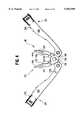
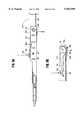
- FIG. 1is a top perspective view which shows the preferred embodiment of the present invention as it appears when opened with the plier jaws closed;
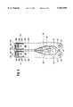
- FIG. 2is a bottom perspective view of the opened inventive tool with the plier jaws closed;
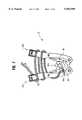
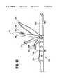
- FIG. 3is a top view of the open compound tool with the plier jaws open;
- FIG. 4is a top view of the compound tool partially closed
- FIG. 5is a top view of the compound tool almost closed
- FIG. 6is a top view of the closed compound tool
- FIG. 7illustrates a use of the present invention clamping a cable
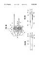
- FIG. 8Ais a sectional top view of the ends of the handles of the compound tool with two supplemental tools extended, showing the latching and locking mechanism in operation;
- FIGS. 8B and 8Cshow side views of two supplemental tools
- FIG. 9Ais a side view of the compound tool illustrating the release of the latching mechanism
- FIG. 9Bis a cross-sectional side view of one of the supplemental tools releasing the locking mechanism
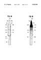
- FIG. 10is a sectional side view of one of the handles of the compound tool with the supplemental tools stored therein in varying degrees of extension;
- FIG. 11is a reversed sectional side view of the other of the handles of the compound tool with the supplemental tools stored therein in varying degrees of extension;
- FIGS. 12 and 13show side views of the two plier jaws separated and facing one another
- FIG. 14is a side view of one of the jaws of the pliers from the outside as seen along the lines 14--14 in FIG. 12;
- FIG. 15is a side view of the jaw of FIG. 14 from the inside as seen along the lines 15--15 in FIG. 12;
- FIG. 16is a front end view of the jaw of FIG. 14 as seen along the lines 16--16 in FIG. 12;
- FIG. 17is a sectional, cross-sectional view of the laminated structure of the plier jaws as seen along the lines 17--17 in FIG. 12;
- FIG. 18is an enlarged side view of a preferred embodiment of a rivet used with the plier jaws of the present invention.
- a preferred embodiment of a multi-purpose folding tool, combination tool, or compound tool of the present inventionis indicated generally by reference numeral 10 and is seen in its opened or unfoled state in FIG. 1 and its closed or folded state in FIG. 6. When opened, it has the overall form of a pair of pliers. When closed, tool 10 is box-shaped and occupies a relatively small amount of space with relatively smooth external surfaces.
- FIGS. 1-6For the sake of clarity in the drawings, the reference numerals in FIGS. 1-6 have been placed on a figure only if a particular feature is most clearly shown in that figure. In other words, including reference numerals for all of the features shown in each figure has been avoided in the interest of clarity.
- compound tool 10is shown in the form of a cross-jawed pliers 12 comprising a gripping end 14 and a handle end 16.
- Gripping end 14includes a pair of plier jaws 18 and 20; handle end 16 includes a pair of handles 22 and 24.
- Pliers 12are cross-jawed pliers inasmuch as jaw 18 is connected across a pivot pin 26 to handle 24 and jaw 20 is connected across pivot pin 26 to handle 22.
- Pliers 12preferably comprise needlenose pliers, and, while this is the preferred embodiment, any other plier shape could be substituted.
- jaw 18is functionally divided into a nose 28, a bearing 30, and a tang 32.
- jaw 20is preferably although not necessarily a mirror image of jaw 18 and also comprises a nose 34, a bearing 36, and a tang 38.
- jaw 18 and jaw 20are rotationally joined together by aligning apertures 40 and 42 in bearings 30 and 36, respectively, and extending pivot pin 26 therethrough (FIGS. 1 and 4).
- Jaws 18 and 20present opposing, generally flat surfaces 44 and 46 for gripping flat objects, arcuate surfaces 48 and 50 for gripping round, square, or hexagonally shaped objects, and cutting surfaces 52 and 54 for cutting materials such as wire, all as is well known in the art. Surfaces 44-50 may be serrated as desired to improve their gripping abilities. The remaining features of jaws 18 and 20 will be introduced as they arise in the following description of the invention.
- handle 22is pivotally attached to tang 38 of jaw 20 by a pivot pin 56, while handle 24 is pivotally attached to tang 32 of jaw 18 by a pivot pin 58.
- Pins 56 and 58extend through a pair of apertures 60 and 62, respectively, formed in tangs 38 and 32 (FIGS. 12-13).
- Pivot pins 26, 56, and 58are parallel and extend generally outwardly from the plane of the drawings, providing rotational movement thereabout in the plane of the drawings. This is an important feature for it provides the pliers 12 of the present invention with more structural stability than prior art compound tools in which the plier jaws fold into the handles along axes perpendicular to the plier's pivot, such as found in Collins et al., U.S. Pat. No. 5,062,173, and Frazer, U.S. Pat. No 5,267,366.
- handles 22 and 24are best seen in the perspective views of FIGS. 1 and 2 to which attention is now directed. Common features in each handle will be given the same reference numeral for simplicity and clarity of description.
- Handles 22 and 24are channel shaped with each handle being formed by a pair of upstanding sidewalls, namely by an interior sidewall 64 and an exterior sidewall or outboard wall 66, which are connected by a web 68.
- interior sidewall 64 and an exterior sidewall or outboard wall 66are connected by a web 68.
- exteriorare relative terms and are used here with reference to the views in FIGS. 1-3, where compound tool 10 is shown in its opened state. In the closed state of FIGS. 4-6, the relationship between “exterior” and “interior” obviously reverses.
- Sidewalls 64 and 66 and web 68define an internal channel 70 partially open toward the bottom of tool 10, as seen in FIG. 2.
- a partial web 72(FIG.
- Prior art compound toolswhich also include channel-shaped handles for housing supplemental tools, such as Leatherman, (U.S. Pat. Nos. 4,238,862, 4,744,272, and 4,888,869), European Patent Application 513,937, Collins et al. (U.S. Pat. Nos. Des. 368,634 and 5,062,173), Sessions et al. (U.S. Pat. Nos. 5,142,721 and 5,212,844), and Frazer (U.S. Pat. Nos. Des. 368,634 and 5,267,366), show U-shaped channels throughout the length of their handles. Since the foregoing do not have the enclosed, box beam construction of the handles of the present invention, they lack the torsional resistance required when twisting pliers 12 against a heavy load.
- Channel 70houses a plurality of supplemental tools 76 (FIG. 2) which may be stored therein and retrieved therefrom. More particularly, sidewalls 64 and 66 and webs 68 and 72 leave an opening to channel 70 through which supplemental tools 76 may be rotated about a pair of pivot pins 78 (that extend between the ends of sidewalls 64 and 66) from their stored positions shown in FIG. 2 to their extended positions, some of which are shown, for example, in FIGS. 8A and 9-11.
- channel 70opens toward the bottom of tool 10, in contrast to the side tool openings shown in so many of the prior art compound tools mentioned above, so supplemental tools 76 of the present invention are facing away from the palm of the hand when pliers 12 are being used.
- Sidewalls 64 and 66 and webs 68 of handles 22 and 24are solid sheets, so that there are no rough surfaces or standing handle edges to cause discomfort to one's hand when squeezing handle end 16 of the present invention.
- a plurality of raised, rounded nubs 80 or various other configurationsmay be added to exterior sidewalls 66 to improve the user's grip on handles 22 and 24 without adding potentially painful sharp edges.
- handles 22 and 24provide important functional results which distinguishes the present invention from the prior art. More particularly, as seen in FIG. 3, webs 68 of handles 22 and 24 include a tapered portion 82 positioned between two portions having substantially constant widths, namely, a wider end portion 84 adjacent end 86 and a narrower waist portion 88 adjacent pivot bearing 90, to delineate a pair of recesses or jaw recess portions 92 positioned on exterior sidewalls 66.
- recesses 92afford a very comfortable nesting area for the thumb and fingers to grip pliers 12.
- recesses 92combine to provide an area for storing plier jaws 18 and 20 when compound tool 10 is fully closed, as seen in FIG. 6.
- Tapered portions 82are dimensioned and located so as to complement the shape of a pair of tapered portions 94 formed on plier jaws 18 and 20 (FIGS. 3 and 12-13); the smaller, constant width waist portion 88 mates with a pair of flat sides 96 of plier jaws 18 and 20; and the curved portion 89 between waist portion 88 and annular bearing 90 snugly fits around annular bearings 30 and 36.
- external recesses 92store gripping end 14 of the pliers 12 externally of the handles' walls, leaving more interior room in the handles for supplemental tools 76.
- storing the gripping end 14 externally of compound tool 10allows pliers 12 to be used to clamp items, hands-free, for an extended period of time, as will be seen in FIG. 7 to be discussed in greater detail below.
- FIGS. 3-6illustrate the manner in which pliers 12 fold into the closed state of compound tool 10.
- Handles 22 and 24are pulled apart, as in FIG. 3, until a pair of outer shoulders 98 (FIGS. 3 and 12-13) come into contact with vertical portions of shoulders 104, at which time jaws 18 and 20 cease to diverge.
- Further outward pressure on handles 22 and 24overcomes the inherent friction between handles 22 and 24 and tangs 32 and 38, and the plier's handles 22 and 24 begin to converge, as seen in FIG. 4.
- a pair of tip portions 100 of jaws 18 and 20are substantially separated from each other in their fully open position, as shown for example in FIGS. 4 and 5. Further movement of handles 22 and 24 towards one another results in the orientation of handles and jaws as shown in FIG. 5.
- tips 100 of jaws 18 and 20contact tapered surfaces or contact portions 82 of exterior (now interior) sidewalls 66 which cam the jaws 18 and 20 together, also forcing tangs 32 and 38 and handle bearings 90 towards one another.
- Continued pressurebrings compound tool 10 finally to the fully closed position shown in FIG. 6. In the latter position, tip portions 100 touch each other.
- edges 102 at the pivot end of interior sidewalls 64 adjacent bearings 90are in contact with shoulders 104 of tangs 32 and 38 (FIGS. 12-13).
- the forces generated by squeezing handles 22 and 24are directed from edges 102 through shoulders 104, which, being offset from their pivot pins 26, 56, and 58, applies a force rotating jaws 18 and 20 of pliers 12 together.
- Each of the interior sidewalls 64is a relatively planar, solid sheet which is integrally connected with web 68 and sidewall 66. With the force vectors essentially lying within the plane of sidewalls 64, a very stable structure is provided which can withstand high clamping pressures.
- FIG. 7A multi-strand cable 106 is clamped in jaws 18 and 20 with tool 10 in a semi-closed state.
- An aperture 108is preferably formed through web 68 of handle 24 and is adapted to receive, when desired, a lanyard 110.
- Lanyard 110provides a convenient way to carry tool 10 on a belt or back-pack. It also allows tool 10 to clamp cable 106, or other desired item, by closing tool 10 with cable 106 between the jaws 18 and 20 of pliers 12, and by wrapping lanyard 110 tightly around handles 22 and 24. Tool 10 will continue to clamp cable 106 without the necessity of gripping the pliers in one's hands. As noted above, this advantage is due to the storing of gripping end 14 externally of the handles when tool 10 is closed.
- Supplemental tools 76 and their relationship to tool 10will now be described with reference to FIGS. 8-11.
- supplemental toolsto include in any particular model of tool 10 is discretionary with the manufacturer of tool 10, depending on its intended audience.
- a fisherman's toolmight include supplemental tools useful for fishing, e.g., a serrated blade for cleaning fish, a whetstone for sharpening fish hooks, scissors for cutting line, and an assortment of knife blades
- an electrician's toolmight include an assortment of screwdrivers, a wire insulation cutter and stripper, a saw, a file, and a ruler.
- the supplemental tools included in this preferred embodimentare therefore only exemplary of the possibilities.
- FIG. 10a side view of a section of handle 22 is shown with five supplemental tools 76: a bottle/can opener 112, a Phillips head screwdriver 114, a scribe 116, a clip blade 118, and a file 120.
- FIG. 11shows the other handle 24 with five additional tools: a small screwdriver 122, a combination large screwdriver/wire stripper 124, a scraper 126, a sheepfoot blade 128, and a ruler 142.
- the supplemental tools 76have been rotated to varying degrees of extension to illustrate them better; they would not normally be used as shown. Normally, only one supplemental tool 76 would be extended at any given time.
- Tool 10should be closed, as in FIG. 8A (note the location of nubs 80), to provide a hefty handle for the screwdriver.
- FIG. 8Ais a partial top view of the ends of handles 22 and 24 intended to illustrate, along with FIGS. 8B, 8C, 9A and 9B, the operation of the latching and locking mechanism of the present invention. It should be understood that in FIG. 8A, both screwdriver 114 and ruler 142 are shown extended from their respective s handles 22 and 24; however, during actual use, only one such tool will be extended at any given time.
- webs 68 of handles 22 and 24each include a resilient tongue 132 integral with and cantilevered from web 68.
- Tongue 132is separated from sidewalls 64 and 66 by slits 133, and, being free from contact with handles 22 and 24 except where joined to web 68, tongue 132 comprises a leaf spring which is free to flex when deflected.
- a pair of recesses 134inwardly and oppositely extend at the side junction between tongue 132 and web 68 to aid in the flexibility of tongue 132.
- a rectangular aperture or slot 136is formed adjacent the free end 137 of tongue 132 and is bordered by two side strips 138 and a transverse stock 140.
- Stock 140has an outer edge 158 defining the outer edge surface of free end 137, and an interior edge surface 157 defining the locking edge surface of slot 136.
- Flat tongue 132, flat stock 140, and flat web 68are essentially coplanar when tongue 132 is in its at-rest, unflexed state. Compare FIGS. 10-11 where tongue 132 is at rest with FIGS. 9A-9B where tongue 132 has been deflected into its flexed state.
- Ruler 142(FIGS. 8A and 8B) is typical of a supplemental tool 76 mounted on pivot pin 78 outboard of the other tools in handle 24 and, therefore, in alignment with one of the side strips 138.
- File 120is another such outboard mounted supplemental tool which is, however, located in the other handle 22.
- Ruler 142(FIG. 8B) includes a tool body 144 and a mounting end 146.
- Tool body 144is unique to the type of tool 76 included in compound tool 10 and includes whatever working surfaces are important to that particular tool.
- Mounting end 146is constructed substantially the same as the mounting end of other outboard-mounted supplementary tools, such as file 120.
- Mounting end 146includes an aperture 148 for receiving pivot pin 78 and a camming surface 150 having a first flat 152 formed adjacent a stop 154 and a second flat 156 positioned diametrically opposite to first flat 152.
- the radial width of camming surface 150is slightly more than the distance between pivot pin 78 and tongue 132, whereas the radial width of flats 152 and 156 are substantially equal to that distance.
- ruler 142In operation, when ruler 142 is in its fully extended position in longitudinal alignment with handle 24 (as shown in FIG. 8A, or when file 120 is in its fully extended position as shown in FIG. 9A), flat 152 is flush with the unflexed tongue 132, and stop 154 is in contact with outer edge 158 of stock 140. Stop 154 and edge 158 prevent ruler 142 (and any other similar supplemental tool such as file 120) from rotating beyond its alignment with handle 24.
- the flex-resisting force of tongue 132urges stock 140 against flat 152 and thus biases ruler 142 and file 120 toward their fully extended positions, not preventing closure thereof but requiring an additional force be applied to overcome the bias. As such, ruler 142 and file 120 will be latched, as opposed to being positively locked (as some of the interior tools can be which will be described in greater detail shortly).
- file 120When in its closed position, housed within channel 70 of handle 22, file 120 is biased to its closed position by resilient tongue 132 pressing on flat 156, effectively holding file 120 in place.
- camming surface 150flexes tongue 132 (arrow B in FIG. 9A) slightly outwardly from the plane of web 68. If flats 152 and 156 were not of slightly less radial distance from pivot pin 78 than the remainder of camming surface 150, file 120 would not be held in its closed and extended positions, but rather would flop about uncontrollably.
- File 120 and ruler 142are merely illustrative of outboard mounted tools, or possibly an inboard mounted tool, which do not need to be positively locked in their open, extended positions.
- Clip blade 118(FIG. 8C) is illustrative of an inboard mounted supplementary tool which needs for safety reasons to be positively locked in its open, extended position.
- Clip blade 118is shown having a body 144 appropriate to its function. Included in body 144 of clip blade 118 is a nail nick 159 to facilitate opening of clip blade 118. Some outboard tools, such as file 120 and ruler 142, have a notch 160 on their top edge when they are closed, to allow access to interior tools having nail nicks 159, such as bottle/can opener 112, scribe 116, clip blade 118, large screwdriver/wire stripper 124, and scraper 126. Handles 22 and 24 likewise include notches 162 (FIGS. 1, 9A and 10) for the same reason.
- the mounting end 146 of clip blade 118includes a pivot pin aperture 148, a camming surface 150, and a flat 156, all provided for the same purposes as described in connection with ruler 142.
- Mounting end 146 of clip blade 118differs, however, from those of non-positively locked outboard tools in that in place of flat 152 and stop 154, mounting end 146 of clip blade 118 has a U-shaped locking transverse notch 164 located to mate with stock 140 of tongue 132.
- clip blade 118is biased toward its closed position by tongue 132 acting upon flat 156.
- tongue 132flexes (arrow B), because it is riding on the radially enlarged camming surface 150, until stock 140 snaps into U-shaped notch 164 of clip blade 118.
- aperture 136(the smaller of its rectangular dimensions) must be large enough to enclose the portion of camming surface 150 that is located to the right of notch 164 as viewed in FIG. 8C in order to prevent the camming of stock 140 out of notch 164 by camming surface 150. Other than that, the dimensions of aperture 136 are not significant except for structural considerations.
- the width of stock 140(the smaller of its rectangular dimensions) is critical, however. It must be such that stock 140 fits snugly in notch 164. Stock 140 will remain in notch 164 until positively, forcibly removed. Before that occurs, therefore, clip blade 118 is positively locked in place.
- the upstanding edge surfaces 165 and 167(FIGS. 8A and 8C) of U-shaped notch 164 abut edge surfaces 158 and 157, respectively, of stock 140.
- the coaction of edge surfaces 158 and 167prevents rotation of tool 144 in one direction, thereby preventing tool 144 from opening beyond the desired extended position.
- the coaction of edge surfaces 157 and 165prevents rotation of tool 144 in the other direction, thereby preventing tool 144 from unintentionally closing, i.e., leaving the desired extending position.
- the locking mechanism described hereinis a radical departure from prior art locking mechanisms, and has profound benefits associated therewith; as such it is an important feature of the present invention.
- Bassett(U.S. Pat. No. 2,798,290) is representative of prior art patents which utilize a transverse slot or a leaf spring, but not both together, in the handle of a compound tool as part of a locking mechanism for tools.
- Bassett's knifeblade 41has a detent lobe 28 on the peripheral surface of its mounting end. Locking of blade 41 is effected by a radially projecting, smoothly arcuate lobe 28 either "engaging slot 42 with detent action (FIGS. 6-7, and column 3, line 72 of Bassett) or being allowed to flex leaf spring 29 "to assume a position on spring 29 past dead center” (FIGS. 1-3, column 3, lines 30-31 of Bassett).
- lobe 28includes an arcuate camming surface which bends the edges of slot 42 in fixed base 43, when lobe 28 is being placed therein or removed therefrom; there is no leaf spring involved. In the latter, there is no notch for lobe 28 to enter; leaf spring 29 merely provides a bias for an over-dead-center latch.
- a projection on mounting end 146is not equivalent to a notch 164 being formed therein. Provision of a radial projection on the mounting end requires a reduction in the radial width of the annular ring surrounding the pivot pin which provides the structural support for the blade; a notch does not remove any material except to form the relatively small notch.
- Prior art locking mechanismswhich include a locking aperture in the housing inevitably include a projection on the blade to enter the locking aperture.
- Those members of the prior art which utilize a notch in the bladealso traditionally provide a projection which fits in the notch to lock the blade, e.g., an L-shaped flange on the end of a separate element.
- Representative of this time-honored class, which are legion,are Barnard & Brace, U.S. Pat. No. 97,154, issued in November of 1869, and Evrell, U.S. Pat. No. 4,669,188.
- the addition of the extra locking elementdecreases the number of supplemental tools which can be housed in the tool while increasing the number of elements required for a functional tool and concomitantly the manufacturing costs.
- FIGS. 9A-9Bthe release means for the locking mechanism is illustrated in FIGS. 9A-9B.
- At least two of the supplemental tools 76, one in each handle, shown as scribe 116 in FIGS. 9A, 9B, and 10, and scraper 126 in FIG. 11,have a bulge 166 on their upper surfaces which protrudes above the open side edges 170 of sidewalls 64 and 66 when tools 76 are closed.
- Manual depression (arrows C, FIGS. 9A-9B) of bulge 166rotates scribe 116 counter-clockwise (as viewed in FIGS.
- FIGS. 14-17An important feature of the present invention is the laminated construction of the plier jaws, illustrated in detail in FIGS. 14-17, where the same reference numerals used in FIGS. 12-13 identify the same features.
- jaw 18is shown as comprising a central body 172 laminated with two outer strips 174 and 176.
- FIG. 17is a sectional view of jaw 18 (taken along lines 17--17 of FIG. 12), wherein central body 172 and outer strips 174 and 176 are not shown to scale; in practice, central body 172 is much thicker than outer strips 174, 176, closer to the illustrations of FIGS. 14 and 15.
- central body 172being the heftier of the pieces, includes countersinks 178 which mate with daps 180 formed in outer strips 174 and 176.
- Countersinks 178 and daps 180are preferably circular, but any convenient shape will do so long as they mate snugly.
- the countersink/dap combinationprevents lateral sliding of the two outer strips relative to the central body and maintains the pieces in their relative orientations.
- Central body 172 and outer strips 174 and 176can be secured together by any known means which is not detrimental to the use of pliers 12.
- a preferred method of securing the laminatesutilizes rivets 182, countersunk at 184 (FIG. 18), to provide added strength and to positively prevent separation of the laminates.
- the laminated central body 172 and outer strips 174 and 176are shaped as plier jaws as shown in FIGS. 14-16, jaw 20 being a mirror image of jaw 18, though some other shape, if advantageous, could be desirable.
- Central body 172extends the full length of jaw 18 from tip 100 through bearing 32.
- Outer strip 176extends similarly except that its forwardmost portion 187 does not extend as far as tip 100.
- Outer strip 174terminates at its lower end at recess 186 adjacent bearing 30 which receives bearing 36 from jaw 20, when the two jaws are rotatably joined by pivot pin 26.
- the upper end of outer strip 174terminates in a tip 187 that is the same as the uppermost tip of outer strip 176.
- Tip 100 of central body 172is tapered on both sides thereof as at 188.
- tips 187 of outer strips 174 and 176are each tapered on both sides thereof as at 189.
- jaws 18 and 20comprise a pair of needlenose pliers. This needlenose effect is enhanced by having the tips 187 of outer strips 174 and 176 terminate rearwardly of tip 100, as previously described.
- plier jaws 12as shown and described above is believed to be significantly stronger than non-laminated plier jaws.
Landscapes
- Engineering & Computer Science (AREA)
- Mechanical Engineering (AREA)
- Knives (AREA)
- Gripping Jigs, Holding Jigs, And Positioning Jigs (AREA)
Abstract
Description
Claims (54)
Priority Applications (2)
| Application Number | Priority Date | Filing Date | Title |
|---|---|---|---|
| US09/099,367US5963999A (en) | 1996-10-07 | 1998-06-18 | Multi-purpose folding tool |
| US09/373,911US6219870B1 (en) | 1996-10-07 | 1999-08-13 | Lock release mechanism for a folding combination tool or the like |
Applications Claiming Priority (2)
| Application Number | Priority Date | Filing Date | Title |
|---|---|---|---|
| US08/724,963US5791002A (en) | 1996-10-07 | 1996-10-07 | Multi-purpose folding tool |
| US09/099,367US5963999A (en) | 1996-10-07 | 1998-06-18 | Multi-purpose folding tool |
Related Parent Applications (1)
| Application Number | Title | Priority Date | Filing Date |
|---|---|---|---|
| US08/724,963ContinuationUS5791002A (en) | 1996-10-07 | 1996-10-07 | Multi-purpose folding tool |
Related Child Applications (1)
| Application Number | Title | Priority Date | Filing Date |
|---|---|---|---|
| US09/373,911DivisionUS6219870B1 (en) | 1996-10-07 | 1999-08-13 | Lock release mechanism for a folding combination tool or the like |
Publications (1)
| Publication Number | Publication Date |
|---|---|
| US5963999Atrue US5963999A (en) | 1999-10-12 |
Family
ID=24912585
Family Applications (3)
| Application Number | Title | Priority Date | Filing Date |
|---|---|---|---|
| US08/724,963Expired - LifetimeUS5791002A (en) | 1996-10-07 | 1996-10-07 | Multi-purpose folding tool |
| US09/099,367Expired - LifetimeUS5963999A (en) | 1996-10-07 | 1998-06-18 | Multi-purpose folding tool |
| US09/373,911Expired - LifetimeUS6219870B1 (en) | 1996-10-07 | 1999-08-13 | Lock release mechanism for a folding combination tool or the like |
Family Applications Before (1)
| Application Number | Title | Priority Date | Filing Date |
|---|---|---|---|
| US08/724,963Expired - LifetimeUS5791002A (en) | 1996-10-07 | 1996-10-07 | Multi-purpose folding tool |
Family Applications After (1)
| Application Number | Title | Priority Date | Filing Date |
|---|---|---|---|
| US09/373,911Expired - LifetimeUS6219870B1 (en) | 1996-10-07 | 1999-08-13 | Lock release mechanism for a folding combination tool or the like |
Country Status (1)
| Country | Link |
|---|---|
| US (3) | US5791002A (en) |
Cited By (34)
| Publication number | Priority date | Publication date | Assignee | Title |
|---|---|---|---|---|
| USD424900S (en)* | 1999-07-26 | 2000-05-16 | Allied International, Inc. | Double jawed pliers |
| USD426446S (en)* | 1999-09-15 | 2000-06-13 | Alltrade Inc. | Multi-function tool |
| USD426447S (en)* | 1999-09-15 | 2000-06-13 | Alltrade Inc. | Multifunction tool |
| US6161291A (en)* | 1998-12-16 | 2000-12-19 | Gilmour, Inc. | Lopping apparatus having handle compartments for stowing blades during periods of non-use and associated method |
| USD458822S1 (en) | 2001-07-13 | 2002-06-18 | American Tool Companies, Inc. | Locking pliers with toolset pocket |
| USD458821S1 (en) | 2001-07-13 | 2002-06-18 | American Tool Companies, Inc. | Locking pliers with toolset pocket |
| USD472438S1 (en) | 2001-10-29 | 2003-04-01 | American Tool Companies, Inc. | Locking pliers with toolset pocket |
| US20040016058A1 (en)* | 2000-12-26 | 2004-01-29 | Gardiner Walter A. | Multi-purpose equipment |
| US20050278865A1 (en)* | 2004-06-15 | 2005-12-22 | Michael West | Fishing tool |
| US7039973B1 (en)* | 2004-03-17 | 2006-05-09 | Lehmann Roger W | Fishing pliers with hook sharpening file |
| US20070131069A1 (en)* | 2004-01-13 | 2007-06-14 | Leatherman Tool Group, Inc. | Multipurpose folding tool with tool bit holder and blade lock |
| USD568710S1 (en) | 2007-01-10 | 2008-05-13 | Leatherman Tool Group, Inc. | Folding multipurpose hand tool |
| USD571181S1 (en) | 2007-01-10 | 2008-06-17 | Leatherman Tool Group, Inc. | Folding multipurpose hand tool with carabiner |
| USD573009S1 (en) | 2007-01-10 | 2008-07-15 | Leatherman Tool Group, Inc. | Portion of a carabiner |
| USD573437S1 (en) | 2007-01-10 | 2008-07-22 | Leatherman Tool Group, Inc. | Portion of a handle piece for a folding multipurpose hand tool |
| USD573865S1 (en) | 2007-01-10 | 2008-07-29 | Leatherman Tool Group, Inc. | Folding hand tool with visible pliers |
| WO2008150497A1 (en)* | 2007-05-31 | 2008-12-11 | Padden Stephen J | Plier tool combination |
| USD592931S1 (en) | 2007-01-10 | 2009-05-26 | Leatherman Tool Group, Inc. | Accessory retainer and housing of a folding multipurpose hand tool |
| US7684017B2 (en) | 2006-10-26 | 2010-03-23 | Callaway Golf Company | Laser range finder for use on a golf course |
| US20100122420A1 (en)* | 2008-11-20 | 2010-05-20 | Fiskars Brands, Inc. | Multi-function tool with locking pliers |
| USD620771S1 (en) | 2009-10-23 | 2010-08-03 | Gilmour, Inc. | Lopper |
| USD621234S1 (en) | 2009-10-23 | 2010-08-10 | Gilmour, Inc. | Lopper |
| USD623038S1 (en) | 2009-08-07 | 2010-09-07 | Fiskars Brands, Inc. | Handle for a multi-function tool |
| USD623039S1 (en) | 2009-08-07 | 2010-09-07 | Fiskars Brands, Inc. | Handle for a multi-function tool |
| USD626810S1 (en) | 2009-11-06 | 2010-11-09 | Leatherman Tool Group, Inc. | Hand tool |
| USD630080S1 (en) | 2010-05-27 | 2011-01-04 | Fiskars Brands, Inc. | Handle for a multi-function tool |
| USD632539S1 (en) | 2009-04-13 | 2011-02-15 | Taylor Brands, Llc | Knife handle |
| USD635002S1 (en) | 2009-12-18 | 2011-03-29 | Leatherman Tool Group, Inc. | Hand tool |
| USD639627S1 (en) | 2010-05-27 | 2011-06-14 | Fiskars Brands, Inc. | Communication tool |
| US20110154577A1 (en)* | 2009-12-31 | 2011-06-30 | Cormac Eubanks | Integrated tire repair multi tool with folding pliers |
| US20110162213A1 (en)* | 2010-01-07 | 2011-07-07 | Gilmour, Inc. | Lopping Shears |
| US20130180054A1 (en)* | 2012-01-14 | 2013-07-18 | Leatherman Tool Group, Inc. | Hand tool |
| US9701004B2 (en) | 2011-10-25 | 2017-07-11 | Fiskars Brands, Inc. | Multi-purpose tool having removable handle for use as a hand tool |
| USD961349S1 (en)* | 2021-01-15 | 2022-08-23 | James White | Bottle opener |
Families Citing this family (34)
| Publication number | Priority date | Publication date | Assignee | Title |
|---|---|---|---|---|
| US5960498A (en)* | 1997-07-18 | 1999-10-05 | The Coleman Company, Inc. | Foldable tool with removable tool cartridges |
| US6014787A (en) | 1997-10-30 | 2000-01-18 | Leatherman Tool Group, Inc. | Multipurpose folding tool with easily accessible outer blades |
| US6038735A (en)* | 1998-03-02 | 2000-03-21 | Chang; Chung-Min | Handle for a compact tool |
| US6282996B1 (en) | 1999-01-29 | 2001-09-04 | Leatherman Tool Group, Inc. | Multipurpose locking pliers |
| US6276241B1 (en) | 1999-02-18 | 2001-08-21 | Snap-On Technologies, Inc. | Laminated adjustable wrench |
| CA2328592C (en)* | 2000-01-12 | 2006-03-28 | Benjamin C. Rivera | Folding multipurpose tool including blade lock release mechanism |
| US6510767B1 (en) | 2000-01-12 | 2003-01-28 | Leatherman Tool Goup, Inc. | Folding multipurpose tool including blade lock release mechanism |
| US6324712B1 (en) | 2000-05-16 | 2001-12-04 | Victorinox Ag | Plier jaws having a wire cutting structure |
| USD454044S1 (en) | 2000-06-19 | 2002-03-05 | Alterra Holdings Corporation | Tool handle |
| USD445326S1 (en) | 2000-06-19 | 2001-07-24 | Alterra Holdings Corporation | Tool handle with pad |
| US6725748B1 (en)* | 2002-10-30 | 2004-04-27 | Awi Acquisition Company | Collapsible pliers |
| US7062856B2 (en)* | 2003-06-30 | 2006-06-20 | United Cutlery Corporation | Folding tool |
| US20050072004A1 (en)* | 2003-10-03 | 2005-04-07 | Carter Fred J. | Opening assist mechanism for a folding knife |
| US7347128B2 (en)* | 2004-01-13 | 2008-03-25 | Leatherman Tool Group, Inc. | Multipurpose folding tool with tool bit holder and blade lock |
| USD499621S1 (en) | 2004-02-25 | 2004-12-14 | Leatherman Tool Group, Inc. | Hub portion of a pair of jaws for a tool |
| US7017448B2 (en)* | 2004-04-23 | 2006-03-28 | Ideal Industries, Inc. | Precision hand-held wire stripper |
| US20050278866A1 (en)* | 2004-06-17 | 2005-12-22 | Isaac Madarieta | Multi-function tool for surfers |
| US7249390B2 (en)* | 2005-01-07 | 2007-07-31 | Leatherman Tool Group, Inc. | Multipurpose tool including holder for replaceable tool blades |
| JP4717450B2 (en)* | 2005-01-28 | 2011-07-06 | 株式会社基陽 | Clipper |
| US7082856B1 (en)* | 2005-06-14 | 2006-08-01 | E5 Products, Inc. | Wire stripper system |
| US7353736B2 (en) | 2005-07-27 | 2008-04-08 | Leatherman Tool Group, Inc. | Enhanced multi-function hand tool |
| US7793570B2 (en)* | 2007-04-17 | 2010-09-14 | Brigham Young University | Tension locking tool |
| US9120236B2 (en)* | 2011-05-10 | 2015-09-01 | Julio Cesar Herrera Cardenas | Combination folding tool and method of handle deployment |
| US9289891B1 (en)* | 2013-02-14 | 2016-03-22 | Gary Dean Ragner | Folding multitools |
| US9770820B1 (en)* | 2013-04-29 | 2017-09-26 | Gary Dean Ragner | Folding pliers with full wrench set |
| US9555533B2 (en)* | 2013-08-15 | 2017-01-31 | Lincoln Global, Inc. | Welding pliers multi-tool |
| US20150266177A1 (en)* | 2014-03-21 | 2015-09-24 | Richard Conklin | Multi-purpose locking pliers |
| USD764885S1 (en)* | 2014-05-09 | 2016-08-30 | Jpj Investment Holding Corp. | Tube cutter |
| US20160052120A1 (en)* | 2014-08-22 | 2016-02-25 | Hobart Brothers Company | Multifunctional welding apparatus |
| US10919558B2 (en)* | 2017-12-19 | 2021-02-16 | Mando Corporation | Steering apparatus for vehicle |
| EP3946817B1 (en) | 2019-03-26 | 2025-04-23 | Fiskars Brands, Inc. | Multi-function tool with laminated plier jaws |
| US11364612B1 (en)* | 2020-08-17 | 2022-06-21 | James R. Campbell | Multi-functional chainsaw field maintenance tool |
| US20240173824A1 (en)* | 2022-11-30 | 2024-05-30 | Chukwuma Marcellus Eleodimuo | chuma-pliers |
| USD1062421S1 (en)* | 2024-06-30 | 2025-02-18 | Ouyang Yu | Multi-tool carabiner |
Citations (38)
| Publication number | Priority date | Publication date | Assignee | Title |
|---|---|---|---|---|
| DE30788C (en)* | F. W. KLEVER F. SOHN in Solingen | Innovation in scissors knives | ||
| US97154A (en)* | 1869-11-23 | Improvement in pocket-knife | ||
| US234378A (en)* | 1880-11-09 | Geoege h | ||
| US288397A (en)* | 1883-11-13 | Combination-tool | ||
| US526480A (en)* | 1894-09-25 | William a | ||
| US649334A (en)* | 1900-01-30 | 1900-05-08 | Iver P Meloos | Key-wrench. |
| US831676A (en)* | 1905-10-27 | 1906-09-25 | Alvord M Mcleran | Combination wire-working tool. |
| US858003A (en)* | 1906-08-09 | 1907-06-25 | Friedrich Wilhelm Klever | Pocket-tool scissors. |
| US1174132A (en)* | 1916-01-05 | 1916-03-07 | John Dragun | Convertible tongs or pliers. |
| US1334425A (en)* | 1919-01-22 | 1920-03-23 | Henry G Wernimont | Combination-tool |
| US1461270A (en)* | 1922-04-05 | 1923-07-10 | Garrison Frank | Tool |
| US1467661A (en)* | 1922-09-21 | 1923-09-11 | Valley Forge Cutlery Company | Tool |
| US1474592A (en)* | 1922-07-29 | 1923-11-20 | George Browning | Pliers |
| US1524694A (en)* | 1923-07-21 | 1925-02-03 | Maio Louis Di | Folding scissors |
| US2575652A (en)* | 1947-08-19 | 1951-11-20 | Ransom Y Bovee | Pocket tweezer article |
| US2720799A (en)* | 1954-07-26 | 1955-10-18 | Pfost Leland | Process for molding a wrench and hard-metal insert used therein |
| US2753741A (en)* | 1954-04-01 | 1956-07-10 | Riley Specialty Inc | Fisherman's shot pliers |
| US3044081A (en)* | 1959-10-26 | 1962-07-17 | Jr Jewell Robinson | Pliers |
| US4238862A (en)* | 1978-07-13 | 1980-12-16 | Leatherman Timothy S | Pocket multiple tool |
| US4502220A (en)* | 1981-12-10 | 1985-03-05 | Takaaki Aoki | Hand-held type opening and closing action tool |
| US4512051A (en)* | 1981-10-27 | 1985-04-23 | Magan Arthur S C | Handtool |
| US4648145A (en)* | 1983-03-28 | 1987-03-10 | Miceli Philip V | Folding pocket tool and knife |
| US4660241A (en)* | 1985-10-10 | 1987-04-28 | Chen Ching Win | Multipurpose pliers |
| US4662252A (en)* | 1985-09-18 | 1987-05-05 | Warheit William A | Auto-grip pliers |
| US4744272A (en)* | 1986-04-17 | 1988-05-17 | Leatherman Tool Group, Inc. | Foldable tool |
| US4888869A (en)* | 1986-04-17 | 1989-12-26 | Leatherman Tool Group, Inc. | Lock-bar foldable tool |
| US5062173A (en)* | 1989-11-02 | 1991-11-05 | Collins Michael C | Multifunction tool |
| US5142721A (en)* | 1991-03-08 | 1992-09-01 | Fiskars Oy Ab | Pocket tool with retractable jaws |
| US5212844A (en)* | 1991-03-08 | 1993-05-25 | Fiskars Oy Ab | Pocket tool with retractable jaws |
| US5267366A (en)* | 1992-05-27 | 1993-12-07 | Spencer Frazer | Combination hand tool with retractable pliers jaws |
| US5351584A (en)* | 1991-12-11 | 1994-10-04 | Warheit William A | Plier tool assembly |
| US5491856A (en)* | 1994-06-29 | 1996-02-20 | Legg; Larry K. | Foldable multiple function tool |
| USD368634S (en) | 1995-03-23 | 1996-04-09 | Spencer Frazer | Combination hand tool |
| US5526571A (en)* | 1992-11-30 | 1996-06-18 | Fiskars Oy Ab | Pivoted tool with foldable handles |
| USD371498S (en) | 1995-05-22 | 1996-07-09 | Combination hand tool | |
| USD382182S (en) | 1996-01-11 | 1997-08-12 | Buck Knives, Inc. | Combination tool |
| USD384872S (en) | 1996-09-04 | 1997-10-14 | Shih-Yuan Yeh | Pair of pliers |
| USD401133S (en) | 1996-07-31 | 1998-11-17 | Imperial Schrade Corp. | Multi-purpose folding pliers |
Family Cites Families (13)
| Publication number | Priority date | Publication date | Assignee | Title |
|---|---|---|---|---|
| US1015026A (en) | 1909-11-30 | 1912-01-16 | Wayne Jackson | Combination-tool. |
| US988068A (en) | 1910-02-23 | 1911-03-28 | John W Beardsley | Knife. |
| US1373993A (en) | 1920-02-26 | 1921-04-05 | Edwin A Halseth | Knife |
| US1486725A (en) | 1923-02-03 | 1924-03-11 | Wallace R Brown | Knife |
| US1561993A (en) | 1923-05-29 | 1925-11-17 | Nielsen Frederik | Combination tool |
| US1556788A (en) | 1924-07-07 | 1925-10-13 | Hallvarson Peter William | Combination tool |
| US2851704A (en) | 1956-04-03 | 1958-09-16 | Hugo E Zoeller | Sheath with latch for folding tools |
| US2798290A (en) | 1956-10-10 | 1957-07-09 | William E Bassett | Combined tool |
| US4268960A (en) | 1979-08-01 | 1981-05-26 | Cole Consumer Products, Inc. | Knife with blade locking mechanism |
| DE3037588A1 (en) | 1980-10-04 | 1982-05-13 | Heinr. Böker GmbH & Co Baumwerk, 5650 Solingen | FOLDING KNIFE WITH LOCKABLE BLADE |
| US4347665A (en) | 1981-05-11 | 1982-09-07 | Glesser Louis S | Pocket knife |
| EP0100377B1 (en) | 1982-07-30 | 1987-09-30 | Bram Jan Voslamber | A pocket-tool, pocket-knife or similarly retractable tools |
| US4703560A (en) | 1986-03-07 | 1987-11-03 | Hawks Edge, Inc. | Locking knife apparatus |
- 1996
- 1996-10-07USUS08/724,963patent/US5791002A/ennot_activeExpired - Lifetime
- 1998
- 1998-06-18USUS09/099,367patent/US5963999A/ennot_activeExpired - Lifetime
- 1999
- 1999-08-13USUS09/373,911patent/US6219870B1/ennot_activeExpired - Lifetime
Patent Citations (39)
| Publication number | Priority date | Publication date | Assignee | Title |
|---|---|---|---|---|
| DE30788C (en)* | F. W. KLEVER F. SOHN in Solingen | Innovation in scissors knives | ||
| US97154A (en)* | 1869-11-23 | Improvement in pocket-knife | ||
| US234378A (en)* | 1880-11-09 | Geoege h | ||
| US288397A (en)* | 1883-11-13 | Combination-tool | ||
| US526480A (en)* | 1894-09-25 | William a | ||
| US649334A (en)* | 1900-01-30 | 1900-05-08 | Iver P Meloos | Key-wrench. |
| US831676A (en)* | 1905-10-27 | 1906-09-25 | Alvord M Mcleran | Combination wire-working tool. |
| US858003A (en)* | 1906-08-09 | 1907-06-25 | Friedrich Wilhelm Klever | Pocket-tool scissors. |
| US1174132A (en)* | 1916-01-05 | 1916-03-07 | John Dragun | Convertible tongs or pliers. |
| US1334425A (en)* | 1919-01-22 | 1920-03-23 | Henry G Wernimont | Combination-tool |
| US1461270A (en)* | 1922-04-05 | 1923-07-10 | Garrison Frank | Tool |
| US1474592A (en)* | 1922-07-29 | 1923-11-20 | George Browning | Pliers |
| US1467661A (en)* | 1922-09-21 | 1923-09-11 | Valley Forge Cutlery Company | Tool |
| US1524694A (en)* | 1923-07-21 | 1925-02-03 | Maio Louis Di | Folding scissors |
| US2575652A (en)* | 1947-08-19 | 1951-11-20 | Ransom Y Bovee | Pocket tweezer article |
| US2753741A (en)* | 1954-04-01 | 1956-07-10 | Riley Specialty Inc | Fisherman's shot pliers |
| US2720799A (en)* | 1954-07-26 | 1955-10-18 | Pfost Leland | Process for molding a wrench and hard-metal insert used therein |
| US3044081A (en)* | 1959-10-26 | 1962-07-17 | Jr Jewell Robinson | Pliers |
| US4238862A (en)* | 1978-07-13 | 1980-12-16 | Leatherman Timothy S | Pocket multiple tool |
| US4512051A (en)* | 1981-10-27 | 1985-04-23 | Magan Arthur S C | Handtool |
| US4502220A (en)* | 1981-12-10 | 1985-03-05 | Takaaki Aoki | Hand-held type opening and closing action tool |
| US4648145A (en)* | 1983-03-28 | 1987-03-10 | Miceli Philip V | Folding pocket tool and knife |
| US4662252A (en)* | 1985-09-18 | 1987-05-05 | Warheit William A | Auto-grip pliers |
| US4660241A (en)* | 1985-10-10 | 1987-04-28 | Chen Ching Win | Multipurpose pliers |
| EP0513937A2 (en)* | 1986-04-17 | 1992-11-19 | Leatherman Tool Group, Inc. | Foldable tool |
| US4744272A (en)* | 1986-04-17 | 1988-05-17 | Leatherman Tool Group, Inc. | Foldable tool |
| US4888869A (en)* | 1986-04-17 | 1989-12-26 | Leatherman Tool Group, Inc. | Lock-bar foldable tool |
| US5062173A (en)* | 1989-11-02 | 1991-11-05 | Collins Michael C | Multifunction tool |
| US5212844A (en)* | 1991-03-08 | 1993-05-25 | Fiskars Oy Ab | Pocket tool with retractable jaws |
| US5142721A (en)* | 1991-03-08 | 1992-09-01 | Fiskars Oy Ab | Pocket tool with retractable jaws |
| US5351584A (en)* | 1991-12-11 | 1994-10-04 | Warheit William A | Plier tool assembly |
| US5267366A (en)* | 1992-05-27 | 1993-12-07 | Spencer Frazer | Combination hand tool with retractable pliers jaws |
| US5526571A (en)* | 1992-11-30 | 1996-06-18 | Fiskars Oy Ab | Pivoted tool with foldable handles |
| US5491856A (en)* | 1994-06-29 | 1996-02-20 | Legg; Larry K. | Foldable multiple function tool |
| USD368634S (en) | 1995-03-23 | 1996-04-09 | Spencer Frazer | Combination hand tool |
| USD371498S (en) | 1995-05-22 | 1996-07-09 | Combination hand tool | |
| USD382182S (en) | 1996-01-11 | 1997-08-12 | Buck Knives, Inc. | Combination tool |
| USD401133S (en) | 1996-07-31 | 1998-11-17 | Imperial Schrade Corp. | Multi-purpose folding pliers |
| USD384872S (en) | 1996-09-04 | 1997-10-14 | Shih-Yuan Yeh | Pair of pliers |
Non-Patent Citations (20)
| Title |
|---|
| "BuckTool, Blitz and Big Nut Bust Out!", story about "BuckTool", Blade, Jul. '96, pp. 52, 54. |
| American Camper Tool, in public use before Oct. 7, 1996.* |
| Bear MGC Cutlery Bear Jaws Product Description, issued before Oct. 7, 1996.* |
| Buck Knives BuckTool advertisement, published before Oct. 7, 1996.* |
| BuckTool, Blitz and Big Nut Bust Out , story about BuckTool , Blade , Jul. 96, pp. 52, 54.* |
| Coast Pliers + Plus™ Product Description, Item No. C201000, issued before Oct. 7, 1996. |
| Coast Pliers Plus Product Description, Item No. C201000, issued before Oct. 7, 1996.* |
| Generic Multi Function Pocket Tool Product Description, issued before Oct. 7, 1996.* |
| Gerber Military Provisional Tool (MPT) Product Description, Item Nos. 55511 and 55721, issued before Oct. 7, 1996.* |
| Gerber Multi Plier Tool (MPT) Product Description, Item Nos. 55800, 55850, 55860, 55890, 50002, 50003, 50004, 55782, and 55200, issued before Oct. 7, 1996.* |
| Gerber Multi-Plier™ Tool (MPT) Product Description, Item Nos. 55800, 55850, 55860, 55890, 50002, 50003, 50004, 55782, and 55200, issued before Oct. 7, 1996. |
| Gerber Tool, in public use before Oct. 7, 1996.* |
| Leatherman Pocket Crimper Survival Tool Product Description, issued before Oct. 7, 1996.* |
| Leatherman Pocket Survival Tool II (PST II ) Product Description, issued before Oct. 7, 1996.* |
| Leatherman Pocket Survival Tool II (PST II™) Product Description, issued before Oct. 7, 1996. |
| Leatherman Pocket Survival Tool Product Description, issued before Oct. 7, 1996.* |
| Leatherman Pocket Survival Tool™ Product Description, issued before Oct. 7, 1996. |
| Leatherman Super Tool Product Description, issued before Oct. 7, 1996.* |
| Leatherman Tool (the original) Product Description, issued before Oct. 7, 1996.* |
| Yorkcraft Road Warrior Tool Product Description, issued before Oct. 7, 1996.* |
Cited By (44)
| Publication number | Priority date | Publication date | Assignee | Title |
|---|---|---|---|---|
| US6161291A (en)* | 1998-12-16 | 2000-12-19 | Gilmour, Inc. | Lopping apparatus having handle compartments for stowing blades during periods of non-use and associated method |
| US6434834B2 (en) | 1998-12-16 | 2002-08-20 | Gilmour, Inc. | Lopping apparatus having stowable blades and associated method |
| USD424900S (en)* | 1999-07-26 | 2000-05-16 | Allied International, Inc. | Double jawed pliers |
| USD426446S (en)* | 1999-09-15 | 2000-06-13 | Alltrade Inc. | Multi-function tool |
| USD426447S (en)* | 1999-09-15 | 2000-06-13 | Alltrade Inc. | Multifunction tool |
| US20040016058A1 (en)* | 2000-12-26 | 2004-01-29 | Gardiner Walter A. | Multi-purpose equipment |
| US7125145B2 (en) | 2000-12-26 | 2006-10-24 | Taylor Cutlery Llc | Multi-purpose equipment |
| USD458822S1 (en) | 2001-07-13 | 2002-06-18 | American Tool Companies, Inc. | Locking pliers with toolset pocket |
| USD458821S1 (en) | 2001-07-13 | 2002-06-18 | American Tool Companies, Inc. | Locking pliers with toolset pocket |
| USD472438S1 (en) | 2001-10-29 | 2003-04-01 | American Tool Companies, Inc. | Locking pliers with toolset pocket |
| US20070131069A1 (en)* | 2004-01-13 | 2007-06-14 | Leatherman Tool Group, Inc. | Multipurpose folding tool with tool bit holder and blade lock |
| US7634956B2 (en)* | 2004-01-13 | 2009-12-22 | Leatherman Tool Group, Inc. | Multipurpose folding tool with tool bit holder and blade lock |
| US7039973B1 (en)* | 2004-03-17 | 2006-05-09 | Lehmann Roger W | Fishing pliers with hook sharpening file |
| US20050278865A1 (en)* | 2004-06-15 | 2005-12-22 | Michael West | Fishing tool |
| US8279417B2 (en) | 2006-10-26 | 2012-10-02 | Callaway Golf Company | Laser range finder for use on a golf course |
| US7684017B2 (en) | 2006-10-26 | 2010-03-23 | Callaway Golf Company | Laser range finder for use on a golf course |
| USD568710S1 (en) | 2007-01-10 | 2008-05-13 | Leatherman Tool Group, Inc. | Folding multipurpose hand tool |
| USD571181S1 (en) | 2007-01-10 | 2008-06-17 | Leatherman Tool Group, Inc. | Folding multipurpose hand tool with carabiner |
| USD573009S1 (en) | 2007-01-10 | 2008-07-15 | Leatherman Tool Group, Inc. | Portion of a carabiner |
| USD573437S1 (en) | 2007-01-10 | 2008-07-22 | Leatherman Tool Group, Inc. | Portion of a handle piece for a folding multipurpose hand tool |
| USD573865S1 (en) | 2007-01-10 | 2008-07-29 | Leatherman Tool Group, Inc. | Folding hand tool with visible pliers |
| USD592931S1 (en) | 2007-01-10 | 2009-05-26 | Leatherman Tool Group, Inc. | Accessory retainer and housing of a folding multipurpose hand tool |
| WO2008150497A1 (en)* | 2007-05-31 | 2008-12-11 | Padden Stephen J | Plier tool combination |
| US20100122420A1 (en)* | 2008-11-20 | 2010-05-20 | Fiskars Brands, Inc. | Multi-function tool with locking pliers |
| US7908944B2 (en) | 2008-11-20 | 2011-03-22 | Fiskars Brands, Inc. | Multi-function tool with locking pliers |
| USD632539S1 (en) | 2009-04-13 | 2011-02-15 | Taylor Brands, Llc | Knife handle |
| USD623038S1 (en) | 2009-08-07 | 2010-09-07 | Fiskars Brands, Inc. | Handle for a multi-function tool |
| USD623039S1 (en) | 2009-08-07 | 2010-09-07 | Fiskars Brands, Inc. | Handle for a multi-function tool |
| USD621234S1 (en) | 2009-10-23 | 2010-08-10 | Gilmour, Inc. | Lopper |
| USD620771S1 (en) | 2009-10-23 | 2010-08-03 | Gilmour, Inc. | Lopper |
| USD626810S1 (en) | 2009-11-06 | 2010-11-09 | Leatherman Tool Group, Inc. | Hand tool |
| USD635002S1 (en) | 2009-12-18 | 2011-03-29 | Leatherman Tool Group, Inc. | Hand tool |
| USD635004S1 (en) | 2009-12-18 | 2011-03-29 | Leatherman Tool Group, Inc. | Hand tool |
| US20110154577A1 (en)* | 2009-12-31 | 2011-06-30 | Cormac Eubanks | Integrated tire repair multi tool with folding pliers |
| US20110162213A1 (en)* | 2010-01-07 | 2011-07-07 | Gilmour, Inc. | Lopping Shears |
| US8826545B2 (en) | 2010-01-07 | 2014-09-09 | Robert Bosch Gmbh | Lopping shears |
| USD639627S1 (en) | 2010-05-27 | 2011-06-14 | Fiskars Brands, Inc. | Communication tool |
| USD630080S1 (en) | 2010-05-27 | 2011-01-04 | Fiskars Brands, Inc. | Handle for a multi-function tool |
| US9701004B2 (en) | 2011-10-25 | 2017-07-11 | Fiskars Brands, Inc. | Multi-purpose tool having removable handle for use as a hand tool |
| US10464199B2 (en) | 2011-10-25 | 2019-11-05 | Fiskars Brands, Inc. | Multi-purpose tool having removable handle for use as a hand tool |
| US20130180054A1 (en)* | 2012-01-14 | 2013-07-18 | Leatherman Tool Group, Inc. | Hand tool |
| US8857299B2 (en)* | 2012-01-14 | 2014-10-14 | Leatherman Tool Group, Inc. | Hand tool |
| US9656373B2 (en) | 2012-01-14 | 2017-05-23 | Leatherman Tool Group, Inc. | Hand tool |
| USD961349S1 (en)* | 2021-01-15 | 2022-08-23 | James White | Bottle opener |
Also Published As
| Publication number | Publication date |
|---|---|
| US5791002A (en) | 1998-08-11 |
| US6219870B1 (en) | 2001-04-24 |
Similar Documents
| Publication | Publication Date | Title |
|---|---|---|
| US5963999A (en) | Multi-purpose folding tool | |
| US5781950A (en) | Locking mechanism for a folding combination tool | |
| US6006385A (en) | Multi-tool | |
| US6341423B1 (en) | Multiple purpose automobile tool | |
| US5697114A (en) | Folding multi-tool | |
| US5916277A (en) | Multi-function tool with removable head | |
| US6625832B2 (en) | Multi-function tool with cartridge | |
| US6088861A (en) | Tool with locking fold-out implements | |
| US6523203B2 (en) | Multifunction tool with replaceable implements | |
| CA2617478C (en) | Multipurpose tool | |
| US6038723A (en) | Foldable tool with removable tool cartridged mechanism for securing tool cartridge | |
| US4648145A (en) | Folding pocket tool and knife | |
| US10265841B2 (en) | Multi-function tool | |
| CA2328592A1 (en) | Folding multipurpose tool including blade lock release mechanism | |
| US6721984B1 (en) | Multifunction tool with replaceable implements | |
| US6098225A (en) | Folding hand shears | |
| CA2217117C (en) | Multi-purpose folding tool and locking mechanism therefor | |
| US6550142B1 (en) | Hand tool with retractable implement | |
| AU715004B2 (en) | Gripping tool and a jaw | |
| AU735037B2 (en) | Multi-purpose folding tool | |
| CA2321365A1 (en) | Locking and release mechanism for a folding combination tool | |
| US20060200913A1 (en) | Plier handle | |
| KR200273963Y1 (en) | combinaion pliers |
Legal Events
| Date | Code | Title | Description |
|---|---|---|---|
| STCF | Information on status: patent grant | Free format text:PATENTED CASE | |
| AS | Assignment | Owner name:FIRST UNION NATIONAL BANK, PENNSYLVANIA Free format text:SECURITY AGREEMENT;ASSIGNOR:IMPERIAL SCHRADE CORP.;REEL/FRAME:011667/0980 Effective date:20010315 | |
| FPAY | Fee payment | Year of fee payment:4 | |
| AS | Assignment | Owner name:TAYLOR CUTLERY, LLC, TENNESSEE Free format text:ASSIGNMENT OF ASSIGNORS INTEREST;ASSIGNOR:IMPERIAL SCHRADE CORP.;REEL/FRAME:015320/0445 Effective date:20041028 | |
| AS | Assignment | Owner name:TAYLOR BRANDS LLC, TENNESSEE Free format text:CHANGE OF NAME;ASSIGNOR:TAYLOR CUTLERY LLC;REEL/FRAME:018420/0288 Effective date:20041222 Owner name:TAYLOR BRANDS LLC, TENNESSEE Free format text:CHANGE OF NAME;ASSIGNOR:TAYLOR CUTLERY LLC;REEL/FRAME:018420/0135 Effective date:20041222 | |
| FEPP | Fee payment procedure | Free format text:PAT HOLDER CLAIMS SMALL ENTITY STATUS, ENTITY STATUS SET TO SMALL (ORIGINAL EVENT CODE: LTOS); ENTITY STATUS OF PATENT OWNER: SMALL ENTITY | |
| FPAY | Fee payment | Year of fee payment:8 | |
| FPAY | Fee payment | Year of fee payment:12 | |
| AS | Assignment | Owner name:BTI TOOLS, LLC, MASSACHUSETTS Free format text:ASSIGNMENT OF ASSIGNORS INTEREST;ASSIGNOR:TAYLOR BRANDS, LLC;REEL/FRAME:039666/0799 Effective date:20160801 | |
| AS | Assignment | Owner name:BTI TOOLS, LLC, MASSACHUSETTS Free format text:ASSIGNMENT OF ASSIGNORS INTEREST;ASSIGNOR:TAYLOR BRANDS, LLC;REEL/FRAME:039474/0091 Effective date:20160801 | |
| AS | Assignment | Owner name:BATTENFELD TECHNOLOGIES, INC., MISSOURI Free format text:ASSIGNMENT OF ASSIGNORS INTEREST;ASSIGNOR:BTI TOOLS, LLC;REEL/FRAME:039610/0783 Effective date:20160804 |