US5963770A - Printing system - Google Patents
Printing systemDownload PDFInfo
- Publication number
- US5963770A US5963770AUS09/166,403US16640398AUS5963770AUS 5963770 AUS5963770 AUS 5963770AUS 16640398 AUS16640398 AUS 16640398AUS 5963770 AUS5963770 AUS 5963770A
- Authority
- US
- United States
- Prior art keywords
- print engine
- sheet
- operational
- printing system
- Prior art date
- Legal status (The legal status is an assumption and is not a legal conclusion. Google has not performed a legal analysis and makes no representation as to the accuracy of the status listed.)
- Expired - Lifetime
Links
- 230000004044responseEffects0.000claimsdescription12
- 238000004891communicationMethods0.000claimsdescription3
- 230000001105regulatory effectEffects0.000claims2
- 230000007257malfunctionEffects0.000abstractdescription4
- 238000012423maintenanceMethods0.000abstract1
- 239000000843powderSubstances0.000description8
- 238000012546transferMethods0.000description6
- 239000002245particleSubstances0.000description4
- 239000000463materialSubstances0.000description3
- 238000012986modificationMethods0.000description3
- 230000004048modificationEffects0.000description3
- 238000013459approachMethods0.000description2
- 238000013461designMethods0.000description2
- 238000003384imaging methodMethods0.000description2
- 238000010924continuous productionMethods0.000description1
- 239000008187granular materialSubstances0.000description1
- 150000002500ionsChemical class0.000description1
- 239000007788liquidSubstances0.000description1
- 230000007246mechanismEffects0.000description1
- 239000007921spraySubstances0.000description1
Images
Classifications
- G—PHYSICS
- G03—PHOTOGRAPHY; CINEMATOGRAPHY; ANALOGOUS TECHNIQUES USING WAVES OTHER THAN OPTICAL WAVES; ELECTROGRAPHY; HOLOGRAPHY
- G03G—ELECTROGRAPHY; ELECTROPHOTOGRAPHY; MAGNETOGRAPHY
- G03G15/00—Apparatus for electrographic processes using a charge pattern
- G03G15/22—Apparatus for electrographic processes using a charge pattern involving the combination of more than one step according to groups G03G13/02 - G03G13/20
- G03G15/23—Apparatus for electrographic processes using a charge pattern involving the combination of more than one step according to groups G03G13/02 - G03G13/20 specially adapted for copying both sides of an original or for copying on both sides of a recording or image-receiving material
- G03G15/231—Arrangements for copying on both sides of a recording or image-receiving material
- G—PHYSICS
- G03—PHOTOGRAPHY; CINEMATOGRAPHY; ANALOGOUS TECHNIQUES USING WAVES OTHER THAN OPTICAL WAVES; ELECTROGRAPHY; HOLOGRAPHY
- G03G—ELECTROGRAPHY; ELECTROPHOTOGRAPHY; MAGNETOGRAPHY
- G03G2215/00—Apparatus for electrophotographic processes
- G03G2215/00016—Special arrangement of entire apparatus
- G03G2215/00021—Plural substantially independent image forming units in cooperation, e.g. for duplex, colour or high-speed simplex
Definitions
- This inventionrelates to a printing system, and more particularly, concerns a plurality of print engines adapted to form duplex prints with one print engine being redundant and non-operable while the remaining print engines are operative.
- a typical printing systems adapted for use in high speed printingemploys two print engines arranged in tandem. Each print engine prints on one side of the sheet. In this way, duplex prints are formed rapidly and at a high productivity.
- Each print enginemay be an electrophotographic print engine. These print engines are identical to one another and have a photoconductive member that is charged to a substantial uniform potential so as to sensitize the surface thereof. The charged portion of the photoconductive member is exposed to a light image of a document being printed. Exposure of the charged photoconductive member effectively dissipates the charge thereon in the irradiated areas to record an electrostatic latent image on the photoconductive member corresponding to the informational areas desired to be printed.
- the latent imageis developed by bringing a developer material into contact therewith.
- the electrostatic latent imageis developed with dry developer material comprising carrier granules having toner particles adhering triboelectrically thereto.
- a liquid developer materialmay be used as well.
- the toner particlesare attracted to the latent image, forming a visible powder image on the photoconductive surface.
- the toner powder imageis transferred to a sheet. Thereafter, the toner powder image is heated to permanently fuse it to the sheet. After the toner powder image has been formed on one side of the sheet, the sheet is advanced to the next print engine to have information printed on the other side thereof.
- the sheetmay be inverted or the print engine may be oriented so as to print on the opposed side of the sheet.
- both print enginesare substantially identical to one another and produce a sheet having information on opposite sides thereof, i.e., a duplex sheet. This is duplex printing.
- electrophotographic print enginesmay be utilized, one skilled in the art will appreciate that any other type of print engines may also be used.
- ink jet print engines, or lithographic print enginesmay be used.
- these print enginesmay be mixed and matched.
- the printing systemdoes not necessarily require only electrophotographic print engines or only ink jet print engines or only lithographic print engines, but rather may have an electrophotographic print engine and an ink jet print engine, or any such combination.
- U.S. Pat. No. 5,568,246; U.S. Pat. No. 5,598,257; and U.S. Pat. No. 5,730,535,disclose a printing system including two print engines arranged in tandem. Each print engine includes an inverter. The print engines are electrophotographic printing machines. As stated in U.S. Pat. No. 5,568,246; if one of the print engines fails, the other print engine can still be utilized. In this case, the normal single engine duplexing operation is used.
- a printing systemincluding a first print engine adapted to print information on either side of a sheet.
- a second print engineis adapted to print information on either side of the sheet as well.
- a third print engineis adapted to print information on either side of the sheet.
- the third print engineis non-operative in response to the first print engine and the second print engine being operative to print information on opposed sides of the sheet.
- the third print engineis operative, in response to either the first print engine or the second print engine being non-operative.
- the third print engineis adapted to print information on the side of the sheet opposed to the side of the sheet having information printed thereon by either the first print engine or the second print engine.
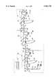
- the printing systemincludes print engine 10, print engine 12, and print engine 14. At any one time, only two print engines are operational. The print engines are identical to one another. Thus, the sheet having information printed thereon passes through two of the three print engines and bypasses the third non-operational print engine. In response to one of the operational print engines becoming non-operational, the previously non-operational print engine becomes operational. In this way, two print engines are always operational. The redundant print engine becomes operational when one of the operating print engines becomes non-operational due to a malfunction. It is thus clear that the printing system of the present invention employs two print engines in an operational mode and one print engine in a non-operational or back-up mode. This significantly improves reliability. Furthermore, each print engine is identical to each other, and engine commonality is maintained. This results in significant reliability improvements.
- a sheetis supplied from feed trays 16 or 18 (or optional sheet input 20).
- the sheet from feed tray 16 or 18is advanced in the direction of arrow 22 by transport 24.
- a gate 26directs the sheet either to transport 28 or to bypass transport 30.
- gate 26directs a sheet onto transport 28.
- Transport 28moves the sheet in the direction of arrow 32 to transfer station 34.
- Transport 28moves the sheet in a times relationship with respect to photoconductive belt 36 so that the toner image developed thereon advances in registration with the sheet at transfer station 34.
- Transfer station 34includes corona generators which spray ions onto the back side of the sheet to transfer the toner powder image from photoconductive belt 36 to the sheet.
- transport 38moves the sheet, in the direction of arrow 40, to fusing station 42.
- the toner powder image adhering to the sheetis permanently fixed or fused to the sheet.
- photoconductive belt 36is charged to a substantial uniform potential and then exposed to a light image of the document to be printed. This records an electrostatic latent image on photoconductive belt 36 which is developed with toner particles to form a toner powder image thereon. This toner powder image is transferred to the sheet at transfer station 34.
- the electrostatic latent imageis formed by using a raster output scanner (ROS) which includes a laser imaging system. A laser imaging system is modulated by digital information received thereto.
- ROSraster output scanner
- gate 44deflects the sheet into inverter 46.
- the inverted sheetis then advanced from inverter 46, in the direction of arrow 48, to gate 50 which deflects the sheet along output path 52 to print engine 12.
- Print engine 12operating in the same manner as print engine 10, prints the next set of information on the opposed side of the sheet forming a duplex print.
- the duplexed sheetexits print engine 12 at output path 54 and enters print engine 14.
- gate 26 of print engine 14is positioned so as to deflect the sheet along the bypass transport 30.
- the duplexed sheetexits print engine 14 along output path 56 and moves to a finisher, compiler, or a stacker.
- print engine 12 and print engine 14are operational.
- the sheetis deflected along bypass transport 30 of print engine 10 and enters print engine 12 to have information printed on one side thereof.
- the sheethaving information printed on one side thereof, outputs print engine 12 along path 54 and enters print engine 14.
- gate 26 of print engine 14deflects the sheet away from bypass transport 30 so as to have information printed on the opposed side thereof at transfer station 34 of print engine 14.
- the sheetis advanced to fusing station 42 of print engine 14 and, subsequently, to output path 56.
- print engine 12may be non-operational and print engines 10 and 14 operational.
- the sheethas information printed on the first side thereof by print engine 10 and then enters print engine 12.
- Gate 26 of print engine 12deflects the sheet along bypass transport 30 of print engine 12 to output path 54 where the sheet enters print engine 14.
- print engine 14prints information on the opposed side of the sheet resulting in a duplex print being exited along output path 56.
- Controller 55is in communication with print engines 10, 12, and 14. The controller transmits signals to each one of these print engines to actuate various electrical solenoids, sheet deflectors, motors and/or clutches in selected steps or sequences as programmed. Sheet path sensors or switches are connected to the controller and are coordinated therewith for sensing timing and controlling the positions of the sheet in each of the printing engines. In this way, the position of the sheet is kept track of and the operation of the respective print engine controlled. In operation, controller 55 may also determine a malfunction in one of the print engines and shut that print engine down automatically.
- controller 55In response to one of the print engines being shut down by controller 55, controller 55 actuates the non-operational print engine and adjusts the parameters within the other print engines to ensure that the sheet moves along the appropriate paths in the appropriately timed sequence.
- controller 55may display on a graphic user interface an alert to an operator that one of the print engines is malfunctioning and being shut down. The operator would then actuate the other print engine manually.
- controller 55may merely display a warning to the operator that one of the print engines is malfunctioning and the operator may then shut down that print engine and actuate the redundant or non-operational print engine.
- the printing system architecture using three print enginesalso permits continuous production while one print engine is being serviced.
- This architecturepermits all of the print engines of the same design, eliminating unique design requirements for the non-operating print engine.
- the present inventionis directed to a printing system employing three print engines arranged in tandem with one of the print engines being non-operational while the other two print engines are operational.
- the redundant or non-operational print enginemay be actuated in response to one of the operational print engines developing a malfunction. This significantly increases reliability and ensures that high productivity is maintained on a continuous basis.
Landscapes
- Physics & Mathematics (AREA)
- General Physics & Mathematics (AREA)
- Counters In Electrophotography And Two-Sided Copying (AREA)
- Printers Characterized By Their Purpose (AREA)
- Dot-Matrix Printers And Others (AREA)
- Separation, Sorting, Adjustment, Or Bending Of Sheets To Be Conveyed (AREA)
- Accessory Devices And Overall Control Thereof (AREA)
Abstract
Description
Claims (11)
Priority Applications (2)
| Application Number | Priority Date | Filing Date | Title |
|---|---|---|---|
| US09/166,403US5963770A (en) | 1998-10-05 | 1998-10-05 | Printing system |
| JP27196599AJP4384304B2 (en) | 1998-10-05 | 1999-09-27 | Printing system |
Applications Claiming Priority (1)
| Application Number | Priority Date | Filing Date | Title |
|---|---|---|---|
| US09/166,403US5963770A (en) | 1998-10-05 | 1998-10-05 | Printing system |
Publications (1)
| Publication Number | Publication Date |
|---|---|
| US5963770Atrue US5963770A (en) | 1999-10-05 |
Family
ID=22603167
Family Applications (1)
| Application Number | Title | Priority Date | Filing Date |
|---|---|---|---|
| US09/166,403Expired - LifetimeUS5963770A (en) | 1998-10-05 | 1998-10-05 | Printing system |
Country Status (2)
| Country | Link |
|---|---|
| US (1) | US5963770A (en) |
| JP (1) | JP4384304B2 (en) |
Cited By (38)
| Publication number | Priority date | Publication date | Assignee | Title |
|---|---|---|---|---|
| US6337958B1 (en) | 2000-09-05 | 2002-01-08 | International Business Machines Corporation | Matching the printing characteristics between two engines of a duplex print system |
| US6381440B1 (en)* | 2000-10-26 | 2002-04-30 | OCé PRINTING SYSTEMS GMBH | Printing system having at least three printer devices as well as method for the operation of such a printing system |
| US6567621B2 (en)* | 2001-08-03 | 2003-05-20 | Fuji Xerox Co., Ltd. | Tandem printers system |
| US6608988B2 (en)* | 2001-10-18 | 2003-08-19 | Xerox Corporation | Constant inverter speed timing method and apparatus for duplex sheets in a tandem printer |
| US6786149B1 (en)* | 2003-04-01 | 2004-09-07 | Xerox Corporation | High speed continuous feed printing system |
| US6823786B1 (en)* | 1999-11-07 | 2004-11-30 | Hewlett-Packard Indigo B.V. | Tandem printing system with fine paper-position correction |
| US6851672B1 (en) | 2000-04-18 | 2005-02-08 | Hewlett-Packard Indigo B.V. | Sheet transport position and jam monitor |
| US6912952B1 (en) | 1998-05-24 | 2005-07-05 | Hewlett-Packard Indigo B.V. | Duplex printing system |
| US20050169677A1 (en)* | 2003-12-26 | 2005-08-04 | Chiemi Kaneko | Image formation method and image formation apparatus for same |
| US20060039727A1 (en)* | 2004-08-23 | 2006-02-23 | Xerox Corporation | Printing system with horizontal highway and single pass duplex |
| US20060039728A1 (en)* | 2004-08-23 | 2006-02-23 | Xerox Corporation | Printing system with inverter disposed for media velocity buffering and registration |
| US20060056862A1 (en)* | 2004-09-16 | 2006-03-16 | Sharp Kabushiki Kaisha | Image forming apparatus |
| US20070070430A1 (en)* | 2005-09-12 | 2007-03-29 | Canon Kabushiki Kaisha | Image forming apparatus |
| US7206532B2 (en) | 2004-08-13 | 2007-04-17 | Xerox Corporation | Multiple object sources controlled and/or selected based on a common sensor |
| US20070159670A1 (en)* | 2005-12-23 | 2007-07-12 | Xerox Corporation | Printing system |
| US7305198B2 (en) | 2005-03-31 | 2007-12-04 | Xerox Corporation | Printing system |
| US7310108B2 (en) | 2004-11-30 | 2007-12-18 | Xerox Corporation | Printing system |
| US20080174802A1 (en)* | 2007-01-23 | 2008-07-24 | Xerox Corporation | Preemptive redirection in printing systems |
| US20090091596A1 (en)* | 2007-10-03 | 2009-04-09 | Askeland Ronald A | System and method for print head maintenance during continuous printing |
| US20090102909A1 (en)* | 1999-05-25 | 2009-04-23 | Silverbrook Research Pty Ltd | Wall mounted printer |
| US20090123211A1 (en)* | 2000-09-15 | 2009-05-14 | Silverbrook Research Pty Ltd | Lockable printer |
| US20090153884A1 (en)* | 2007-12-14 | 2009-06-18 | Xerox Corporation | Printing system and method |
| US20090290896A1 (en)* | 2008-05-23 | 2009-11-26 | Young Timothy J | Print engine synchronization system and apparatus |
| US20090290895A1 (en)* | 2008-05-23 | 2009-11-26 | Young Timothy J | Method for print engine synchronization |
| US20090297240A1 (en)* | 2008-05-29 | 2009-12-03 | Dobbertin Michael T | Print engine productivity module inverter |
| US20100067965A1 (en)* | 2008-09-17 | 2010-03-18 | Xerox Corporation | Pass through inverter |
| US7904015B2 (en) | 2006-12-15 | 2011-03-08 | Xerox Corporation | Cut sheet media handling transport |
| US8113650B2 (en) | 2000-09-15 | 2012-02-14 | Silverbrook Resesarch Pty Ltd | Printer having arcuate printhead |
| US9862193B2 (en) | 2015-08-12 | 2018-01-09 | Xerox Corporation | System and method to maintain printheads operational in a continuously printing system |
| US20190167361A1 (en)* | 2013-03-15 | 2019-06-06 | Auris Health, Inc. | User interface for active drive apparatus with finite range of motion |
| US10688283B2 (en) | 2013-03-13 | 2020-06-23 | Auris Health, Inc. | Integrated catheter and guide wire controller |
| US10835153B2 (en) | 2017-12-08 | 2020-11-17 | Auris Health, Inc. | System and method for medical instrument navigation and targeting |
| US10849702B2 (en) | 2013-03-15 | 2020-12-01 | Auris Health, Inc. | User input devices for controlling manipulation of guidewires and catheters |
| US10912924B2 (en) | 2014-03-24 | 2021-02-09 | Auris Health, Inc. | Systems and devices for catheter driving instinctiveness |
| US11020016B2 (en) | 2013-05-30 | 2021-06-01 | Auris Health, Inc. | System and method for displaying anatomy and devices on a movable display |
| US11037464B2 (en) | 2016-07-21 | 2021-06-15 | Auris Health, Inc. | System with emulator movement tracking for controlling medical devices |
| US11179213B2 (en) | 2018-05-18 | 2021-11-23 | Auris Health, Inc. | Controllers for robotically-enabled teleoperated systems |
| US11872007B2 (en) | 2019-06-28 | 2024-01-16 | Auris Health, Inc. | Console overlay and methods of using same |
Families Citing this family (5)
| Publication number | Priority date | Publication date | Assignee | Title |
|---|---|---|---|---|
| US7444108B2 (en)* | 2005-03-31 | 2008-10-28 | Xerox Corporation | Parallel printing architecture with parallel horizontal printing modules |
| JP4877723B2 (en)* | 2005-12-06 | 2012-02-15 | 株式会社リコー | Image forming apparatus |
| JP5383527B2 (en)* | 2010-01-18 | 2014-01-08 | キヤノン株式会社 | Image forming system, control method thereof, control program, and recording medium |
| JP5371800B2 (en)* | 2010-01-18 | 2013-12-18 | キヤノン株式会社 | Image forming system and control method thereof |
| JP5983247B2 (en)* | 2012-09-28 | 2016-08-31 | コニカミノルタ株式会社 | Image forming system |
Citations (7)
| Publication number | Priority date | Publication date | Assignee | Title |
|---|---|---|---|---|
| US4591884A (en)* | 1983-03-10 | 1986-05-27 | Canon Kabushiki Kaisha | Multi-function image recording apparatus |
| US4958187A (en)* | 1987-02-13 | 1990-09-18 | Canon Kabushiki Kaisha | Image forming apparatus for scanning both sides of an original and producing a duplex copy |
| US4972236A (en)* | 1987-04-01 | 1990-11-20 | Minolta Camera Kabushiki Kaisha | Compact image forming apparatus for double-sided and composite copying |
| US5150167A (en)* | 1990-09-10 | 1992-09-22 | Minolta Camera Kabushiki Kaisha | Image forming apparatus |
| US5357329A (en)* | 1991-08-26 | 1994-10-18 | Minolta Camera Kabushiki Kaisha | Image forming apparatus having two image forming units |
| US5568246A (en)* | 1995-09-29 | 1996-10-22 | Xerox Corporation | High productivity dual engine simplex and duplex printing system using a reversible duplex path |
| US5598257A (en)* | 1995-09-29 | 1997-01-28 | Xerox Corporation | Simplex and duplex printing system using a reversible duplex path |
- 1998
- 1998-10-05USUS09/166,403patent/US5963770A/ennot_activeExpired - Lifetime
- 1999
- 1999-09-27JPJP27196599Apatent/JP4384304B2/ennot_activeExpired - Fee Related
Patent Citations (8)
| Publication number | Priority date | Publication date | Assignee | Title |
|---|---|---|---|---|
| US4591884A (en)* | 1983-03-10 | 1986-05-27 | Canon Kabushiki Kaisha | Multi-function image recording apparatus |
| US4958187A (en)* | 1987-02-13 | 1990-09-18 | Canon Kabushiki Kaisha | Image forming apparatus for scanning both sides of an original and producing a duplex copy |
| US4972236A (en)* | 1987-04-01 | 1990-11-20 | Minolta Camera Kabushiki Kaisha | Compact image forming apparatus for double-sided and composite copying |
| US5150167A (en)* | 1990-09-10 | 1992-09-22 | Minolta Camera Kabushiki Kaisha | Image forming apparatus |
| US5357329A (en)* | 1991-08-26 | 1994-10-18 | Minolta Camera Kabushiki Kaisha | Image forming apparatus having two image forming units |
| US5568246A (en)* | 1995-09-29 | 1996-10-22 | Xerox Corporation | High productivity dual engine simplex and duplex printing system using a reversible duplex path |
| US5598257A (en)* | 1995-09-29 | 1997-01-28 | Xerox Corporation | Simplex and duplex printing system using a reversible duplex path |
| US5730535A (en)* | 1995-09-29 | 1998-03-24 | Xerox Corporation | Simplex and duplex printing system using a reversible duplex path |
Cited By (71)
| Publication number | Priority date | Publication date | Assignee | Title |
|---|---|---|---|---|
| US6912952B1 (en) | 1998-05-24 | 2005-07-05 | Hewlett-Packard Indigo B.V. | Duplex printing system |
| US20090102909A1 (en)* | 1999-05-25 | 2009-04-23 | Silverbrook Research Pty Ltd | Wall mounted printer |
| US6823786B1 (en)* | 1999-11-07 | 2004-11-30 | Hewlett-Packard Indigo B.V. | Tandem printing system with fine paper-position correction |
| US6851672B1 (en) | 2000-04-18 | 2005-02-08 | Hewlett-Packard Indigo B.V. | Sheet transport position and jam monitor |
| US6337958B1 (en) | 2000-09-05 | 2002-01-08 | International Business Machines Corporation | Matching the printing characteristics between two engines of a duplex print system |
| US8113650B2 (en) | 2000-09-15 | 2012-02-14 | Silverbrook Resesarch Pty Ltd | Printer having arcuate printhead |
| US7857536B2 (en)* | 2000-09-15 | 2010-12-28 | Silverbrook Research Pty Ltd | Lockable printer |
| US20090123211A1 (en)* | 2000-09-15 | 2009-05-14 | Silverbrook Research Pty Ltd | Lockable printer |
| EP1202134A3 (en)* | 2000-10-26 | 2004-04-07 | Océ Printing Systems GmbH | Printing system with at least three printing devices and method for operating such a printing system |
| US6381440B1 (en)* | 2000-10-26 | 2002-04-30 | OCé PRINTING SYSTEMS GMBH | Printing system having at least three printer devices as well as method for the operation of such a printing system |
| US6567621B2 (en)* | 2001-08-03 | 2003-05-20 | Fuji Xerox Co., Ltd. | Tandem printers system |
| US6608988B2 (en)* | 2001-10-18 | 2003-08-19 | Xerox Corporation | Constant inverter speed timing method and apparatus for duplex sheets in a tandem printer |
| EP1464506A3 (en)* | 2003-04-01 | 2005-04-27 | Xerox Corporation | High speed continuous feed printing system |
| US6786149B1 (en)* | 2003-04-01 | 2004-09-07 | Xerox Corporation | High speed continuous feed printing system |
| US20050169677A1 (en)* | 2003-12-26 | 2005-08-04 | Chiemi Kaneko | Image formation method and image formation apparatus for same |
| US7082282B2 (en)* | 2003-12-26 | 2006-07-25 | Ricoh Company, Ltd. | Image formation method and image formation apparatus for same |
| US7206532B2 (en) | 2004-08-13 | 2007-04-17 | Xerox Corporation | Multiple object sources controlled and/or selected based on a common sensor |
| US7024152B2 (en)* | 2004-08-23 | 2006-04-04 | Xerox Corporation | Printing system with horizontal highway and single pass duplex |
| US20070031170A1 (en)* | 2004-08-23 | 2007-02-08 | Dejong Joannes N | Printing system with inverter disposed for media velocity buffering and registration |
| US7123873B2 (en)* | 2004-08-23 | 2006-10-17 | Xerox Corporation | Printing system with inverter disposed for media velocity buffering and registration |
| US20060039728A1 (en)* | 2004-08-23 | 2006-02-23 | Xerox Corporation | Printing system with inverter disposed for media velocity buffering and registration |
| US7421241B2 (en)* | 2004-08-23 | 2008-09-02 | Xerox Corporation | Printing system with inverter disposed for media velocity buffering and registration |
| US20060039727A1 (en)* | 2004-08-23 | 2006-02-23 | Xerox Corporation | Printing system with horizontal highway and single pass duplex |
| US20060056862A1 (en)* | 2004-09-16 | 2006-03-16 | Sharp Kabushiki Kaisha | Image forming apparatus |
| US7376364B2 (en)* | 2004-09-16 | 2008-05-20 | Sharp Kabushiki Kaisha | Image forming apparatus |
| CN100435036C (en)* | 2004-09-16 | 2008-11-19 | 夏普株式会社 | image forming device |
| US7310108B2 (en) | 2004-11-30 | 2007-12-18 | Xerox Corporation | Printing system |
| US7305198B2 (en) | 2005-03-31 | 2007-12-04 | Xerox Corporation | Printing system |
| US20070070430A1 (en)* | 2005-09-12 | 2007-03-29 | Canon Kabushiki Kaisha | Image forming apparatus |
| US7761029B2 (en)* | 2005-09-12 | 2010-07-20 | Canon Kabushiki Kaisha | Image forming apparatus |
| US20070159670A1 (en)* | 2005-12-23 | 2007-07-12 | Xerox Corporation | Printing system |
| US7746524B2 (en)* | 2005-12-23 | 2010-06-29 | Xerox Corporation | Bi-directional inverter printing apparatus and method |
| US8195081B2 (en) | 2006-12-15 | 2012-06-05 | Xerox Corporation | Cut sheet media handling transport |
| US20110109035A1 (en)* | 2006-12-15 | 2011-05-12 | Spence James J | Cut Sheet Media Handling Transport |
| US7904015B2 (en) | 2006-12-15 | 2011-03-08 | Xerox Corporation | Cut sheet media handling transport |
| US8693021B2 (en)* | 2007-01-23 | 2014-04-08 | Xerox Corporation | Preemptive redirection in printing systems |
| US20080174802A1 (en)* | 2007-01-23 | 2008-07-24 | Xerox Corporation | Preemptive redirection in printing systems |
| US8231198B1 (en) | 2007-10-03 | 2012-07-31 | Hewlett-Packard Development Company, L.P. | Method for print head service during continuous printing |
| US8172359B2 (en) | 2007-10-03 | 2012-05-08 | Hewlett-Packard Development Company, L.P. | System and method for print head maintenance during continuous printing |
| US20090091596A1 (en)* | 2007-10-03 | 2009-04-09 | Askeland Ronald A | System and method for print head maintenance during continuous printing |
| US20090153884A1 (en)* | 2007-12-14 | 2009-06-18 | Xerox Corporation | Printing system and method |
| US8068252B2 (en)* | 2007-12-14 | 2011-11-29 | Xerox Corporation | Printing system and method including active and inactive image marking engines |
| US20090290896A1 (en)* | 2008-05-23 | 2009-11-26 | Young Timothy J | Print engine synchronization system and apparatus |
| US8099009B2 (en) | 2008-05-23 | 2012-01-17 | Eastman Kodak Company | Method for print engine synchronization |
| US20090290895A1 (en)* | 2008-05-23 | 2009-11-26 | Young Timothy J | Method for print engine synchronization |
| US8180242B2 (en) | 2008-05-23 | 2012-05-15 | Eastman Kodak Company | Print engine synchronization system and apparatus |
| US20110164894A1 (en)* | 2008-05-29 | 2011-07-07 | Dobbertin Michael T | Increasing printer productivity in duplex printer |
| US8000645B2 (en) | 2008-05-29 | 2011-08-16 | Eastman Kodak Company | Print engine productivity module inverter |
| US8224226B2 (en) | 2008-05-29 | 2012-07-17 | Eastman Kodak Company | Method for increasing duplex reproduction apparatus productivity by adjusting sheet travel time difference |
| US20090297240A1 (en)* | 2008-05-29 | 2009-12-03 | Dobbertin Michael T | Print engine productivity module inverter |
| EP2166416A3 (en)* | 2008-09-17 | 2012-06-13 | Xerox Corporation | Pass Through Inverter |
| US8320816B2 (en) | 2008-09-17 | 2012-11-27 | Xerox Corporation | Pass through inverter |
| US20100067965A1 (en)* | 2008-09-17 | 2010-03-18 | Xerox Corporation | Pass through inverter |
| US10688283B2 (en) | 2013-03-13 | 2020-06-23 | Auris Health, Inc. | Integrated catheter and guide wire controller |
| US11992626B2 (en) | 2013-03-13 | 2024-05-28 | Auris Health, Inc. | Integrated catheter and guide wire controller |
| US20190167361A1 (en)* | 2013-03-15 | 2019-06-06 | Auris Health, Inc. | User interface for active drive apparatus with finite range of motion |
| US12089912B2 (en) | 2013-03-15 | 2024-09-17 | Auris Health, Inc. | User input devices for controlling manipulation of guidewires and catheters |
| US10849702B2 (en) | 2013-03-15 | 2020-12-01 | Auris Health, Inc. | User input devices for controlling manipulation of guidewires and catheters |
| US11007021B2 (en) | 2013-03-15 | 2021-05-18 | Auris Health, Inc. | User interface for active drive apparatus with finite range of motion |
| US10675101B2 (en)* | 2013-03-15 | 2020-06-09 | Auris Health, Inc. | User interface for active drive apparatus with finite range of motion |
| US11020016B2 (en) | 2013-05-30 | 2021-06-01 | Auris Health, Inc. | System and method for displaying anatomy and devices on a movable display |
| US10912924B2 (en) | 2014-03-24 | 2021-02-09 | Auris Health, Inc. | Systems and devices for catheter driving instinctiveness |
| US9862193B2 (en) | 2015-08-12 | 2018-01-09 | Xerox Corporation | System and method to maintain printheads operational in a continuously printing system |
| US11037464B2 (en) | 2016-07-21 | 2021-06-15 | Auris Health, Inc. | System with emulator movement tracking for controlling medical devices |
| US11676511B2 (en) | 2016-07-21 | 2023-06-13 | Auris Health, Inc. | System with emulator movement tracking for controlling medical devices |
| US11957446B2 (en) | 2017-12-08 | 2024-04-16 | Auris Health, Inc. | System and method for medical instrument navigation and targeting |
| US10835153B2 (en) | 2017-12-08 | 2020-11-17 | Auris Health, Inc. | System and method for medical instrument navigation and targeting |
| US11918316B2 (en) | 2018-05-18 | 2024-03-05 | Auris Health, Inc. | Controllers for robotically enabled teleoperated systems |
| US11179213B2 (en) | 2018-05-18 | 2021-11-23 | Auris Health, Inc. | Controllers for robotically-enabled teleoperated systems |
| US11872007B2 (en) | 2019-06-28 | 2024-01-16 | Auris Health, Inc. | Console overlay and methods of using same |
| US12329485B2 (en) | 2019-06-28 | 2025-06-17 | Auris Health, Inc. | Console overlay and methods of using same |
Also Published As
| Publication number | Publication date |
|---|---|
| JP2000108421A (en) | 2000-04-18 |
| JP4384304B2 (en) | 2009-12-16 |
Similar Documents
| Publication | Publication Date | Title |
|---|---|---|
| US5963770A (en) | Printing system | |
| US6608988B2 (en) | Constant inverter speed timing method and apparatus for duplex sheets in a tandem printer | |
| US7206536B2 (en) | Printing system with custom marking module and method of printing | |
| CA2282846C (en) | Printer and copier for performance-adjusted monochrome and/or chromatic, single-sided or both-sided printing of a recording medium | |
| JP3332464B2 (en) | Method of forming composite color image and printing device | |
| CA1129480A (en) | Printer with duplex printed sheet output | |
| US8224226B2 (en) | Method for increasing duplex reproduction apparatus productivity by adjusting sheet travel time difference | |
| US7811017B2 (en) | Media path crossover for printing system | |
| US20090267285A1 (en) | Media path crossover clearance for printing system | |
| JPH11170637A (en) | Printing system capable of selecting printing medium | |
| US6259871B1 (en) | Paper cooling system | |
| CN102428411A (en) | Dual engine synchronization | |
| CN104298091A (en) | Maximizing speed tolerance during dual engine synchronization | |
| US20110305490A1 (en) | Dual position pre-transfer assembly | |
| US7088948B2 (en) | Adjustment of skew registration of media to a developed image in a printing machine | |
| JPH09507716A (en) | Document printing device | |
| US5420662A (en) | Printer or copier with an arrangement for printing both sides of a recording medium | |
| US5227852A (en) | Transfer blade in an electronic reprographic printing system | |
| US20030228181A1 (en) | Common polarity toner duplexing electrostatographic reproduction machine | |
| JP4447700B2 (en) | Image forming apparatus | |
| US7551875B2 (en) | Wide latitude printing system | |
| JP3762165B2 (en) | Multicolor image forming apparatus | |
| US7636534B2 (en) | Method and device for printing individual sheets with first and second printing groups and an inverter device | |
| US8478173B2 (en) | Limited ozone generator transfer device | |
| US20090035039A1 (en) | Tightly integrated serial hybrid printing system |
Legal Events
| Date | Code | Title | Description |
|---|---|---|---|
| AS | Assignment | Owner name:XEROX CORPORATION, CONNECTICUT Free format text:ASSIGNMENT OF ASSIGNORS INTEREST;ASSIGNOR:EAKIN, PAUL W.;REEL/FRAME:009518/0186 Effective date:19980930 | |
| STCF | Information on status: patent grant | Free format text:PATENTED CASE | |
| AS | Assignment | Owner name:BANK ONE, NA, AS ADMINISTRATIVE AGENT, ILLINOIS Free format text:SECURITY INTEREST;ASSIGNOR:XEROX CORPORATION;REEL/FRAME:013153/0001 Effective date:20020621 | |
| FPAY | Fee payment | Year of fee payment:4 | |
| AS | Assignment | Owner name:JPMORGAN CHASE BANK, AS COLLATERAL AGENT, TEXAS Free format text:SECURITY AGREEMENT;ASSIGNOR:XEROX CORPORATION;REEL/FRAME:015134/0476 Effective date:20030625 Owner name:JPMORGAN CHASE BANK, AS COLLATERAL AGENT,TEXAS Free format text:SECURITY AGREEMENT;ASSIGNOR:XEROX CORPORATION;REEL/FRAME:015134/0476 Effective date:20030625 | |
| REMI | Maintenance fee reminder mailed | ||
| FPAY | Fee payment | Year of fee payment:8 | |
| SULP | Surcharge for late payment | Year of fee payment:7 | |
| FPAY | Fee payment | Year of fee payment:12 | |
| AS | Assignment | Owner name:XEROX CORPORATION, CONNECTICUT Free format text:RELEASE BY SECURED PARTY;ASSIGNOR:JPMORGAN CHASE BANK, N.A. AS SUCCESSOR-IN-INTEREST ADMINISTRATIVE AGENT AND COLLATERAL AGENT TO JPMORGAN CHASE BANK;REEL/FRAME:066728/0193 Effective date:20220822 |