US5963319A - Low noise Raman analyzer system - Google Patents
Low noise Raman analyzer systemDownload PDFInfo
- Publication number
- US5963319A US5963319AUS09/038,438US3843898AUS5963319AUS 5963319 AUS5963319 AUS 5963319AUS 3843898 AUS3843898 AUS 3843898AUS 5963319 AUS5963319 AUS 5963319A
- Authority
- US
- United States
- Prior art keywords
- fiber
- optical fiber
- probe
- filter
- fibers
- Prior art date
- Legal status (The legal status is an assumption and is not a legal conclusion. Google has not performed a legal analysis and makes no representation as to the accuracy of the status listed.)
- Expired - Fee Related
Links
Images


Classifications
- G—PHYSICS
- G01—MEASURING; TESTING
- G01N—INVESTIGATING OR ANALYSING MATERIALS BY DETERMINING THEIR CHEMICAL OR PHYSICAL PROPERTIES
- G01N21/00—Investigating or analysing materials by the use of optical means, i.e. using sub-millimetre waves, infrared, visible or ultraviolet light
- G01N21/84—Systems specially adapted for particular applications
- G01N21/85—Investigating moving fluids or granular solids
- G01N21/8507—Probe photometers, i.e. with optical measuring part dipped into fluid sample
- G—PHYSICS
- G01—MEASURING; TESTING
- G01J—MEASUREMENT OF INTENSITY, VELOCITY, SPECTRAL CONTENT, POLARISATION, PHASE OR PULSE CHARACTERISTICS OF INFRARED, VISIBLE OR ULTRAVIOLET LIGHT; COLORIMETRY; RADIATION PYROMETRY
- G01J3/00—Spectrometry; Spectrophotometry; Monochromators; Measuring colours
- G01J3/02—Details
- G01J3/0205—Optical elements not provided otherwise, e.g. optical manifolds, diffusers, windows
- G01J3/0218—Optical elements not provided otherwise, e.g. optical manifolds, diffusers, windows using optical fibers
- G—PHYSICS
- G01—MEASURING; TESTING
- G01J—MEASUREMENT OF INTENSITY, VELOCITY, SPECTRAL CONTENT, POLARISATION, PHASE OR PULSE CHARACTERISTICS OF INFRARED, VISIBLE OR ULTRAVIOLET LIGHT; COLORIMETRY; RADIATION PYROMETRY
- G01J3/00—Spectrometry; Spectrophotometry; Monochromators; Measuring colours
- G01J3/28—Investigating the spectrum
- G01J3/44—Raman spectrometry; Scattering spectrometry ; Fluorescence spectrometry
- G—PHYSICS
- G01—MEASURING; TESTING
- G01N—INVESTIGATING OR ANALYSING MATERIALS BY DETERMINING THEIR CHEMICAL OR PHYSICAL PROPERTIES
- G01N21/00—Investigating or analysing materials by the use of optical means, i.e. using sub-millimetre waves, infrared, visible or ultraviolet light
- G01N21/62—Systems in which the material investigated is excited whereby it emits light or causes a change in wavelength of the incident light
- G01N21/63—Systems in which the material investigated is excited whereby it emits light or causes a change in wavelength of the incident light optically excited
- G01N21/65—Raman scattering
- G01N2021/653—Coherent methods [CARS]
- G01N2021/656—Raman microprobe
Definitions
- the present inventionrelates to instruments that analyze chemical properties of a specimen using optical means. More particularly, the invention relates to those instruments having an analyzer unit detecting Raman-scattered light from a specimen using a remote probe.
- One aspect of the inventionrelates to improvements to a Raman analyzer system that incorporates one or more optical filters to reduce "noise" (optical interference) originating from e.g. fluorescence or Raman scattering inside the optical fibers themselves.
- a Raman analyzermay include an in situ probe carrying an emitting optical fiber having a metal buffer layer, and a receiving optical fiber. Also included is laser source having a source wavelength, and a first fiber channel carrying light from the laser source to the emitting optical fiber. A second fiber channel carries light from the receiving optical fiber to a spectral detector. A first optical filter such as a bandpass filter that transmits the source wavelength is disposed between the first fiber channel and the emitting optical fiber.
- the improvementincludes placing the first optical filter in a filter module spaced apart from the probe and coupled thereto by a linking fiber.
- the filter moduleprovides an improved environment for the filter, and preferably the linking fiber has a metal buffer layer to further decrease noise.
- a second optical filteris included in the filter module, and another linking fiber is provided between the filter module and the probe.
- both linking fibersare less than 1 meter in length and have a metal fuffer layer for decreased noise.
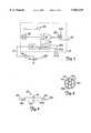
- FIG. 1shows a system diagram of a preferred chemical analyzer in accordance with an aspect of the invention
- FIG. 2depicts chief components of a preferred optical filter used in the analyzer of FIG. 1;
- FIG. 3is an enlarged end view of optical fibers in the probe shown in FIGS. 1 and 5;
- FIG. 4is a perspective end view of a male fiber connector showing an arrangement of optical fibers at the connector end as used in the analyzer of FIG. 1;
- FIG. 5is a partially sectional view of a preferred optical probe useable with the analyzer of FIG. 1;
- FIG. 6is a sectional view of a distal end of the probe of FIG. 5 during probe fabrication
- FIG. 7is a block schematic of a preferred signal conditioning circuit useable with the analyzer of FIG. 1;
- FIG. 8is a schematic of a comparator/asymmetric discriminator circuit depicted as a block in FIG. 7;
- FIG. 9is a timeline showing signals at different points in the signal conditioning circuit of FIG. 7.
- opticalrefers to electromagnetic radiation, whether or not visible to the human eye.
- FIG. 1shows a preferred analyzer 10 that evaluates a specimen of interest 12 and provides on a computer 14 or other suitable output medium an analyzer output indicative of the presence or amount of one or more chemical constituents of the specimen.
- the analyzer 10illuminates the specimen 12 with narrow-band light, collects backscattered light from the specimen, optically isolates a Raman scattering component from the backscattered light, and evaluates the Raman scattering component to calculate the analyzer output. Simultaneously, the analyzer isolates a Rayleigh scattering component from the backscattered light. If the Rayleigh scattering component falls below a threshold level, which may result for example from disconnecting a fiber connector or withdrawing the probe from the specimen, the narrow-band light illumination is shut off. This shut off technique is most effective in specimens such as liquids that have significantly higher Rayleigh scattering levels than that of gasses such as air.
- a diode laser 16launches essentially monochromatic, narrow-band light into a fiber 18a of a 2-by-2 beamsplitter 20.
- a wavelength of about 810 nanometers (nm) for the narrow-band lighthas been found satisfactory. Shorter wavelengths increase the amount of Raman scattering, but may also produce unwanted fluorescence in some specimens; longer wavelengths are less likely to produce fluorescence but yield a lower Raman signal.
- a diode laser having a wavelength between about 750 and 850 nmis preferred. The selected wavelength should not however coincide with an absorption line of the specimen 12, if maximum Raman scattering levels are desired.
- the lasercan have a multimode output and be capable of emitting 700 mW to 1.2 W of optical power during analyzer operation.
- Laser 16also includes a driver circuit with a control input at line 24, and a temperature control circuit if the laser source is a diode laser. The control input of laser 16 controls the amount or intensity of narrow band light injected into fiber 18a.
- Beamsplitter 20divides the laser light launched into fiber 18a between fibers 18b, 22a, preferably in equal amounts although other ratios are also contemplated.
- the narrow band lightpasses from fiber 18b to a fiber 18c via a connector pair 26.
- Connector pair 26includes a male connector end holding each fiber end, the connector ends facing each other inside an alignment bushing. SMA-type connector pairs are preferred for robustness and ease of modification to nonstandard bore sizes, but other known styles such as ST or FC are also contemplated.
- Fiber 18cconnects to a bandpass filter 28 in a fiber termination/filter module 30. Laser light passes through filter 28 to a fiber 18d, which carries the light to a probe 32 adapted to contact the specimen 12. Fibers 18c, 18d are preferably part of armored cable assemblies 34,36 respectively.
- the analyzer 10is preferably arranged as a main analyzer unit 38 situated in a control room (or other suitable location that can provide the necessary electrical power), a probe 32 located at the specimen, and the termination/filter module 30 located near the probe.
- Main analyzer unit 38is preferably housed in an intrinsically safe enclosure, configured with an industry standard Z-purge capability at a port 38a that maintains a positive air pressure inside unit 38 relative to its surroundings.
- Armored fiber cable assemblies 34,36connect unit 38 to module 30, and module 30 to probe 32, respectively. Cable assembly 34 can be tens or hundreds of meters long.
- Optical fibercan itself generate Raman scattering and/or fluorescence (hereinafter, "spurious light signals") from laser light passing through it, which if detected can be confused with Raman scattering from the specimen.
- the spurious light signalsare a function of the fiber properties (most importantly its length, but also including core material, cladding material, and buffer layer material), and generally have wavelengths longer than the laser wavelength. Therefore, bandpass filter 28 is provided in the termination/filter module 30, and module 30 is located as close to the probe as possible to minimize fiber 18d length and thus minimize any spurious light signals generated in fiber 18d.
- the cable assembly 36(including fiber 18d) can be eliminated and the filter 28 and the other filter (74, discussed below) can be mounted directly on the proximal end of the probe 32.
- the temperature or change in temperature encountered even at the proximal end of the probecan have adverse effects on filter performance.
- module 30 mounted away from probe 30provides a more stable temperature environment for the filters 28,74.
- Bandpass filter 28blocks the spurious light signals originating in fibers 18a, 18b, 18c, from reaching fiber 18d, but passes narrow band light from laser 16.
- Spurious light signalscan be further reduced by using silica-based fiber having an inert metal buffer layer such as gold. Such fibers have significantly lower spurious light signals than similar fibers having a polymer-based buffer layer such as polyimide
- the relatively high cost of the metal-coated fibershowever can make it impractical to use them exclusively in analyzer 10, depending on the distances involved.
- the use of filters 28,74permits lower cost, polymer-based fibers to be used between the main analyzer unit 38 and the filters, and the preferred gold-coated fibers to be used in probe 32 and between probe 32 and the filters.
- FIG. 2A preferred embodiment of filter 28 is depicted in FIG. 2.
- Male fiber connectors 39a,39bhold the ends of fibers 18c,18d against 0.25-pitch gradient index (GRIN) lenses 40a,40b respectively.
- a filter 42 sandwiched between lenses 40a,40bprovides the desired spectral filtering characteristics.
- Filter 42preferably comprises an interference-type filter.
- fiber 18dreleasably connects to probe 32 by a connector pair 44 located at a proximal end 32a of probe 32 and passes narrow band light to a fiber 18e that extends from connector pair 44 to a distal end 32b of probe 32.
- a fiber 46a and a group of five fibers 48ahoused in probe 32 are housed in probe 32.
- the line representing fibers 48a, and some other lines in FIG. 1,are shown thickened to indicate multiple optical fibers in the preferred embodiment.
- Fiber 46aconnects to a connector pair 50 at proximal end 32a, and at distal end 32b is brazed or otherwise held in position together with fibers 18e and 48a.
- the fibersare polished to a mirror finish and arranged as shown in FIG. 3.
- a braze material 52holds the fiber ends in place and hermetically seals the probe at end 32b.
- the preferred analyzer 10uses the multiple fibers 48a to boost the detected Raman component and the single fiber 46a to sense the Rayleigh component for continuity.
- Backscattered light traveling down fiber 46ais directed to a detector 56 via fibers 46b-e, connector pairs 58,60, and a bandpass filter 62.
- Filter 62passes the narrow band light wavelength and is substantially identical to previously described filter 28. The purpose of filter 62 is to prevent sunlight, room light, or any other extraneous light collected by fiber 46a from being mistaken for Rayleigh backscattered light. Filter 62 also has the effect of preventing the weaker Raman component, if present, from reaching detector 56.
- An amplifier 64couples to detector 56 to provide an amplified detector output on line 66.
- the detector 56 outputis fed back through a signal conditioning circuit 68 to the laser control input at line 24.
- Circuit 68compares the detector output on line 66 with a predefined threshold. If the detector output is above the threshold, indicating that the analyzer optical system is intact, circuit 68 provides an output on line 24 that maintains laser 16 at its normal, relatively high, output level. If on the other hand the detector output is below the threshold, indicating a fiber disconnection or break, or removal of the probe from the specimen, circuit 68 provides an output on line 24 that shuts off laser 16 or at least controls it to a lower intensity level.
- This lower intensity levelcan be set such that the light intensity emitted from probe fiber 18e, and preferably from fiber 18b, is within BSI/EN 60825-1 class 1 operation (i.e., nonhazardous direct viewing).
- analyzer 10can operate with high laser light levels during normal operation and automatically shut down if a discontinuity is sensed by detector 56, thereby avoiding hazardous viewing by an operator.
- signal conditioning circuit 68Several enhancements to the basic shut-down technique are also provided by signal conditioning circuit 68.
- One enhancementis the ability to discriminate between transient losses in the Rayleigh scattering component, such as may be caused by small bubbles 69 of air or other gas passing through the detection zone 54, and longer lived losses in the signal which may result from fiber disconnection or break, or a withdrawal of probe 32 from the specimen.
- the circuit 68continues driving laser 16 at its high operational intensity level in the presence of the truly transient losses, but shuts the laser down to the lower intensity level for the longer-lived losses. This discrimination function prevents unnecessary and annoying shutdowns during operation of analyzer 10.
- Another enhancementinvolves periodically interrogating the laser 16 after a shutdown has occurred, or at startup, so that if system integrity is restored the analyzer 10 will automatically return to normal operation (i.e., high laser intensity level).
- fibers 48aare unsupported in probe 32 except at distal end 32b, where they are arranged around the emitting fiber as shown in FIG. 3, and at the proximal end 32a, where they are bundled together at a connector pair 70.
- One of the male connector ends 70a of pair 70holds the five fibers 48a as shown in the perspective end view of FIG. 4.
- the other male connector end of pair 70holds a single fiber 48b in alignment with the fibers 48a, where fiber 48b has a diameter sufficiently large to capture light emitted from all of the fibers 48a. For example, if fibers 48 are 100 ⁇ m (core diameter), fiber 48b can be about 300 ⁇ m (core dia.).
- This arrangementgreatly simplifies analyzer 10 interconnections: rather than five separate fibers, connector pairs, and filters connecting the Raman pickup fiber channel from the probe 32 to the main analyzer unit 38, only one-fifth of those components are required by using a large fiber to collect light from fibers 48.
- Backscattered lightis carried by fiber 48b to the entrance slit of an optical spectrograph 72 via a long pass filter 74, fibers 48c-e, and connector pairs 76,78.
- Long pass filter 74has the same construction as the bandpass filter shown in FIG. 2 except that the filter element 42 is fabricated to block the narrow band light of laser 16 and pass longer wavelengths.
- the spectral transmission of filter 74is less than 10 -6 at the laser wavelength 810 nm and rises to half of its peak transmittance (70% typ. peak trans.) at about 833 nm.
- fiber termination/filter module 30is mounted close to probe 32 to keep fiber 48b short (generally no more than a few, and preferably ⁇ 1 meter), so that no spurious light signals can be produced by Rayleigh backscattered light in fiber 48b.
- Filter 74blocks any Rayleigh backscattered light from reaching fibers 48c-e.
- Fiber 48bpreferably has a metal (gold)-buffer layer.
- Fibers 18a-e, 46a, 48a, 48e, and 22a-dare preferably relatively small diameter (e.g. 100 ⁇ m core) fibers, while fibers 48b-d are preferably relatively large diameter (e.g. 300 ⁇ m core) fibers.
- Fibers 46b-ecan be either small or large diameter, but preferably are no smaller than fiber 46a. All can be graded-index or, preferably, step-index for increased light levels.
- Fibers 48eare held at connector pair 78 in a substantially circular pattern (similar to FIG. 4) for optimal coupling to fiber 48d, while at the entrance slit to spectrograph 72 they are held in a linear array.
- Fibers 18d, 18e, 46a, 48a, and 48ball have inert metal buffer layers, preferably gold.
- a diamond reference 80is provided in main analyzer unit 38.
- Fibers 18a, 22a,22bcarry narrow band light from laser 16 to the surface of diamond 80.
- Bandpass filter 82substantially identical to filters 28 and 62, blocks fiber-generated Raman scattering.
- Six fibers 22csurround fiber 22b at the diamond surface (similar to FIG. 3) to capture backscattered light from diamond 80.
- a longpass filter 84substantially identical to filter 74, blocks Rayleigh scattered light from fibers 22d. Fibers 22d, six in number, are arranged circularly at filter 84 and linearly at the spectrograph 72 entrance slit.
- the linear arrays of fibers 22d and 48eare arranged colinearly, one abutting the other, at the entrance slit to spectrograph 72.
- Spectrograph 72is preferably equivalent to model SP-150 available from Acton Research Corp., and has a ruled grating with 400 grooves/mm and blazed at 750 nm.
- a detector array 74preferably 750 pixels wide by 240 pixels high, intercepts and simultaneously monitors the spatially separated Raman scattered light spectra from the specimen 12 and from the diamond reference 80.
- the output from detector array 74is fed to computer 14 over a line 75.
- Signal processing software residing in computer 14is used to produce a standardized Raman spectrum of the specimen (U.S. Pat. No.
- Pattern recognition softwarealso residing in computer 14 calculates the chemical composition of specimen 12 from the standardized Raman spectrum of the specimen and calibration training data. Such pattern recognition software is available from Galactic Industries, Boston, Mass.
- main analyzer unit 38is preferably intrinsically safe. Although computers having intrinsically safe keyboards and monitors are commercially available, there are significant difficulties in providing a convenient and aesthetic user interface using these components. Therefore, computer 14 is preferably equipped with a transceiver 86 such as an antenna or an infrared transmitter/receiver. A user can send instructions to and receive information from computer 14 using a second device such as a laptop computer 88 equipped with a similar transceiver 90. Such communication preferably occurs over a wireless, fiberless free space path 91, allowing the user to freely move from place to place with computer 88 and permitting greater flexibility and choice in a mounting location for main analyzer unit 38.
- a transceiver 86such as an antenna or an infrared transmitter/receiver.
- a usercan send instructions to and receive information from computer 14 using a second device such as a laptop computer 88 equipped with a similar transceiver 90.
- Such communicationpreferably occurs over a wireless, fiberless free space path 91, allowing the
- Preferred transceivers 86,90are commercially available radio LAN cards for desktop or laptop computers, for example the WAVELAN card available from AT&T Lucent Technologies, designed to interface to a standard PC/MCIA slot or Industry Standard Architecture (ISA) bus slot.
- Transceiver 86is depicted in FIG. 1 as such an antenna device, that partially extends out of the housing of unit 38 and connects to computer 14 by a coax line 86a.
- the transceivercan also be an infrared emitter/receiver disposed inside the housing of unit 38 behind a window.
- Computer 88has a keyboard and a mouse that are used to send queries and commands to computer 14.
- Computer 88also has a display to graph or otherwise show the analyzer output data transmitted from computer 14. With this arrangement, computer 14 is preferably equipped with neither a display screen, a keyboard, nor a mouse, to satisfy intrinsic safety requirements as well as to reduce the size, weight, and electrical requirements of main analyzer unit 38.
- Probe 32is described in more detail in connection with FIGS. 5 and 6, together with previously discussed FIGS. 1, 3, and 4.
- Probe 32preferably has a probe body with three main components: a terminus 32c, a shank 32d, and a connector housing 32e, all made of 316 stainless steel or other suitable inert materials capable of withstanding several hundred degree C. temperatures, such as Hastelloy C.
- Terminus 32c, shank 32d, and housing 32eare rotationally symmetric about a probe axis 32f, and are connected by braze joints 92,94 as shown.
- the outer diameter of terminus 32c, braze joint 92, and shank 32dis polished to a smooth finish (0.25 in. dia.) to permit sealing with a ferrule inside the bore of a standard pipe fitting, such as those available from Swagelok Corp., or the bore of some other container that holds specimen 12.
- Fibers 18e, 46a, and 48aextend from their respective male connector ends 44a, 50a, and 70a at proximal probe end 32a to distal end 32b.
- Each of the fibersare step-index, with silica or doped silica core/cladding, and have a thin outer buffer layer of gold, nickel, or other inert metal along their entire length.
- Male connector ends 50a, 44a, and 70aare fixed to connector housing 32e to permit probe 32 to be conveniently disconnected and reconnected to cable assembly 36 for ease of installation and servicing.
- Also affixed to housing 32eis a connector 96 for a temperature sensor 98 included in probe 32.
- Temperature sensor 98is preferably disposed proximate distal end 32b for diagnostic purposes to ensure that probe 32 does not exceed its rated temperature. Alternately, the output of sensor 98 can be used as a rough indication of the specimen temperature, whereupon probe 32 takes on a dual role as a fiber optic chemical analysis probe and a specimen thermometer. Although known fiber optic temperature sensors can be used for sensor 98, electrical sensors are preferable for their simplicity, and most preferable is a thermocouple (e.g. type K) for its low-cost and reliability. The output of sensor 98 can be monitored with a portable, hand-held device coupled directly to connector 96, or with computer 14, in which case an additional channel such as a twisted wire pair can be included in cable assemblies 36,34.
- a portable, hand-held devicecoupled directly to connector 96, or with computer 14, in which case an additional channel such as a twisted wire pair can be included in cable assemblies 36,34.
- terminus 32cis plated with gold 100 or other metal matching the metal buffer layer of the fibers.
- the gold platingextends inside a bore 104 and in the vicinity thereof, but preferably is removed from or not provided on the remaining surfaces of terminus 32c. This is to keep molten braze material in the vicinity of bore 104 during fabrication, preventing it from spreading over the entire terminus 32c.
- An anti-wicking agent or stop-flow substancepreferably a suspension of magnesium hydroxide in water, is applied to each of the fibers in a zone indicated generally at 106 prior to brazing.
- Zone 106approaches but does not touch the distal portion of the fibers that extend into bore 104.
- the anti-wicking agentinhibits the flow of molten braze material along the fibers substantially beyond bore 104.
- the assemblyWith the fibers and terminus 32c so prepared, the assembly is positioned in a vacuum oven 108 as shown in FIG. 6, with a small ring or loop of solid braze material 110 resting on top of terminus 32c at or near bore 104.
- Preferred braze materials for platings 100 made of goldare cadmium-free varieties; widely available braze type (AWS) BAg-8, a binary alloy composed of about 72% silver and 28% copper, is most preferable.
- the vacuum oven 108is then heated to a temperature sufficient to melt braze material 110.
- the molten braze materialdoes not run out of but rather tends to stay in and around the vicinity of bore 104, wicking between the fibers and filling the spaces between them.
- the braze materialforms a solid hermetic seal within bore 104, uniformly filling the inter-fibral spaces inside bore 104 with few or no voids (see FIG. 3).
- a sleeve 112 of terminus 32cis brazed to shank 32d using localized heating, and shank 32d is then brazed to connector housing 32e also using localized heating.
- the sleeve 112partially isolates the brazed fibers in bore 104 from heat generated during brazing of terminus 32c to shank 32d.
- Braze material BAg-8is used for all braze joints.
- the fiber endsare polished to a flat, mirror-smooth finish at distal end 32b.
- the other fiber endsare potted into the male connector ends, which connector ends are also brazed to connector housing 32e at proximal end 32a.
- FIG. 7depicts in block schematic form a preferred signal conditioning circuit 68.
- Circuit 68receives on line 66 the amplified detector output, representative of the Rayleigh scattering component from specimen 12, and provides on line 24 an output that controls a light output level of laser 16.
- a comparator/asymmetric discriminator circuit 114compares the amplified detector output to an adjustable internal threshold.
- the thresholdis adjusted according to the desired laser operational output level, fiber attenuation losses, filter and connector pair losses, and specimen scattering characteristics, to a level less than an output level on line 66 for a fully intact system with the probe contacting the specimen, and greater than a lower output level corresponding to the amount of Rayleigh scattered light received when the probe is withdrawn from the specimen and pointed into the air, or when one of the fiber connector pairs is uncoupled.
- the output of circuit 114feeds into an OR gate 116 and a latch 118 as shown.
- OR gate 116in turn drives a FET transistor 120 which connects directly or through one or more buffer amplifiers if desired to line 24.
- Circuit 114also preferably performs a discrimination function against transient losses of the detected Rayleigh scattering component. This function is described in connection with FIG. 8.
- the latch 118is provided so that computer 14 can monitor the activity of circuit 114.
- An output line 118aconveys the status of the latch to the computer, and a reset line 118b permits the computer to reset the latch.
- circuit 68also includes a low duty cycle pulse generator 122 that also feeds into OR gate 116.
- a pulse having a 5 millisecond (ms) durationis generated at a 1 Hz repetition rate.
- each pulse from generator 122causes the laser to momentarily (for the duration of the pulse) provide the higher output intensity.
- the pulsesare kept short enough, and the duty cycle small enough, to keep the light emitted from probe 32 or even from connector pair 22 below the safety limits for the human eye and for explosive atmosphere environments.
- the Rayleigh backscatter signalwill return to line 66 during one of the pulses, causing circuit 114 to turn "ON", thereby establishing normal analyzer operation.
- OR gate 116Still another input to OR gate 116 is a manual override pushbutton 124. When activated, pushbutton 124 forces laser 16 to the high output intensity. This capability is provided for troubleshooting purposes.
- the amplifier 64is shown in more detail as a first stage transimpedance amplifier and a second stage amplifier with gain.
- the circuit 114is shown as three circuits 114a, 114b, 114c connected in series. Circuit 114a, configured as shown, performs the comparator function described previously. Adjustment of potentiometer 126 adjusts the electric potential at the noninverting input of operational amplifier 128, which electric potential functions as the threshold referred to previously, against which the amplified detector output on line 66 is compared. Since operational amplifier 128 is wired as a comparator, it has essentially a digital output.
- Circuit 114bdiscriminates between positive-going and negative-going transitions.
- the output of op amp 128is LO
- the potential at node 134is LO
- capacitor C1is not charged
- transistor 132is off. If the Rayleigh scattering component suddenly drops below the threshold level, the output of op amp 128 immediately goes HI.
- Diode D1is reverse biased (nonconducting), and the combination of resistors R1, R2, and capacitor C1 delay the turn-on of transistor 132.
- the delay (“ ⁇ ")is proportional to (R1+R2)*C1.
- R1is much greater than R2.
- Preferred delay times ⁇are in the range of about 0 to 44 ms, and are preferably programmable by computer 14 (e.g. by a computer-controlled switch and one or more resistors in circuit 114b that changes the effective resistance in parallel with diode D1).
- circuit 114bdiscriminates between a transitory loss in the detected Rayleigh scattering component and a transitory appearance of such component.
- FIG. 9depicts the output of pulse generator 122, the amplified detector output on line 66, and the output of circuit 114 as waveforms 136, 138, 140 respectively.
- Broken line 142represents the threshold level set in circuit 114.
- the analyzeris powered up, the laser is off, and the probe is withdrawn from the specimen.
- the pulse generatorpulses the laser on, but only a very low Rayleigh scattering component is detected since the probe is not contacting the specimen. Waveform 140 therefore remains off.
- waveform 138By the time t 6 , the large bubble has passed zone 54 and the pulse of waveform 136 brings back the Rayleigh scattering component in waveform 138 and the output of circuit 114. A transitory increase in waveform 138 between t 6 and t 7 has no effect on waveform 140, since waveform 138 stays above threshold 142 during that time. Between time t 7 and t 8 , an interruption such as a fiber break, fiber disconnection, or probe withdrawal occurs. Waveform 138 responds immediately to the interruption, while waveform 140 responds after the delay time ⁇ .
Landscapes
- Physics & Mathematics (AREA)
- Spectroscopy & Molecular Physics (AREA)
- General Physics & Mathematics (AREA)
- Health & Medical Sciences (AREA)
- Life Sciences & Earth Sciences (AREA)
- Chemical & Material Sciences (AREA)
- Analytical Chemistry (AREA)
- Biochemistry (AREA)
- General Health & Medical Sciences (AREA)
- Immunology (AREA)
- Pathology (AREA)
- Nuclear Medicine, Radiotherapy & Molecular Imaging (AREA)
- Investigating, Analyzing Materials By Fluorescence Or Luminescence (AREA)
Abstract
Description
Claims (7)
Priority Applications (1)
| Application Number | Priority Date | Filing Date | Title |
|---|---|---|---|
| US09/038,438US5963319A (en) | 1997-03-14 | 1998-03-11 | Low noise Raman analyzer system |
Applications Claiming Priority (2)
| Application Number | Priority Date | Filing Date | Title |
|---|---|---|---|
| US4109897P | 1997-03-14 | 1997-03-14 | |
| US09/038,438US5963319A (en) | 1997-03-14 | 1998-03-11 | Low noise Raman analyzer system |
Publications (1)
| Publication Number | Publication Date |
|---|---|
| US5963319Atrue US5963319A (en) | 1999-10-05 |
Family
ID=21914732
Family Applications (1)
| Application Number | Title | Priority Date | Filing Date |
|---|---|---|---|
| US09/038,438Expired - Fee RelatedUS5963319A (en) | 1997-03-14 | 1998-03-11 | Low noise Raman analyzer system |
Country Status (4)
| Country | Link |
|---|---|
| US (1) | US5963319A (en) |
| EP (1) | EP0966670A1 (en) |
| JP (1) | JP2001515596A (en) |
| WO (1) | WO1998041848A1 (en) |
Cited By (50)
| Publication number | Priority date | Publication date | Assignee | Title |
|---|---|---|---|---|
| US6244753B1 (en)* | 1997-03-14 | 2001-06-12 | Rosemount Analytical, Inc. | Chemical analyzer optical probe and method of manufacturing same |
| US6310686B1 (en) | 1997-07-02 | 2001-10-30 | Spectracode, Inc. | Raman probe with spatial filter and semi-confocal lens |
| US6313423B1 (en)* | 1996-11-04 | 2001-11-06 | National Recovery Technologies, Inc. | Application of Raman spectroscopy to identification and sorting of post-consumer plastics for recycling |
| US6574490B2 (en) | 2001-04-11 | 2003-06-03 | Rio Grande Medical Technologies, Inc. | System for non-invasive measurement of glucose in humans |
| US6718189B2 (en) | 1995-08-09 | 2004-04-06 | Rio Grande Medical Technologies, Inc. | Method and apparatus for non-invasive blood analyte measurement with fluid compartment equilibration |
| US6816605B2 (en) | 1999-10-08 | 2004-11-09 | Lumidigm, Inc. | Methods and systems for biometric identification of individuals using linear optical spectroscopy |
| US6862091B2 (en) | 2001-04-11 | 2005-03-01 | Inlight Solutions, Inc. | Illumination device and method for spectroscopic analysis |
| US6865408B1 (en) | 2001-04-11 | 2005-03-08 | Inlight Solutions, Inc. | System for non-invasive measurement of glucose in humans |
| US20050162646A1 (en)* | 2004-01-23 | 2005-07-28 | Tedesco James M. | Multi-channel, self-calibrating fiber-coupled raman spectrometers including diagnostic and safety features |
| US20050275832A1 (en)* | 2004-06-10 | 2005-12-15 | The University Of Chicago | Optical apparatus for laser scattering by objects having complex shapes |
| US6983176B2 (en) | 2001-04-11 | 2006-01-03 | Rio Grande Medical Technologies, Inc. | Optically similar reference samples and related methods for multivariate calibration models used in optical spectroscopy |
| US7027848B2 (en) | 2002-04-04 | 2006-04-11 | Inlight Solutions, Inc. | Apparatus and method for non-invasive spectroscopic measurement of analytes in tissue using a matched reference analyte |
| US7126682B2 (en) | 2001-04-11 | 2006-10-24 | Rio Grande Medical Technologies, Inc. | Encoded variable filter spectrometer |
| US7147153B2 (en) | 2003-04-04 | 2006-12-12 | Lumidigm, Inc. | Multispectral biometric sensor |
| US20060278897A1 (en)* | 2005-06-10 | 2006-12-14 | Heller Donald F | Multispectral Energy/Power Meter For Laser Sources |
| US7203345B2 (en) | 1999-10-08 | 2007-04-10 | Lumidigm, Inc. | Apparatus and method for identification of individuals by near-infrared spectrum |
| US7263213B2 (en) | 2003-12-11 | 2007-08-28 | Lumidigm, Inc. | Methods and systems for estimation of personal characteristics from biometric measurements |
| US20070205379A1 (en)* | 2006-03-02 | 2007-09-06 | Chemimage Corporation | System and method for structured illumination and collection for improved optical confocality of raman fiber array spectral translator imaging and interactive raman probing |
| US20070206185A1 (en)* | 2006-03-03 | 2007-09-06 | Chemimage Corporation | System and method for fiber array spectral translator based polymorph screening |
| US7347365B2 (en) | 2003-04-04 | 2008-03-25 | Lumidigm, Inc. | Combined total-internal-reflectance and tissue imaging systems and methods |
| US7394919B2 (en) | 2004-06-01 | 2008-07-01 | Lumidigm, Inc. | Multispectral biometric imaging |
| US20080180661A1 (en)* | 2007-01-29 | 2008-07-31 | Brown Gordon C | Chemical analyzer for industrial process control |
| US7460696B2 (en) | 2004-06-01 | 2008-12-02 | Lumidigm, Inc. | Multispectral imaging biometrics |
| US7471386B2 (en) | 2006-02-27 | 2008-12-30 | Chemimage Corporation | System and method for spectral unmixing in a fiber array spectral translator based polymorph screening system |
| US7508965B2 (en) | 2004-06-01 | 2009-03-24 | Lumidigm, Inc. | System and method for robust fingerprint acquisition |
| US7539330B2 (en) | 2004-06-01 | 2009-05-26 | Lumidigm, Inc. | Multispectral liveness determination |
| US7545963B2 (en) | 2003-04-04 | 2009-06-09 | Lumidigm, Inc. | Texture-biometrics sensor |
| US7613504B2 (en) | 2001-06-05 | 2009-11-03 | Lumidigm, Inc. | Spectroscopic cross-channel method and apparatus for improved optical measurements of tissue |
| US7620212B1 (en) | 2002-08-13 | 2009-11-17 | Lumidigm, Inc. | Electro-optical sensor |
| US7627151B2 (en) | 2003-04-04 | 2009-12-01 | Lumidigm, Inc. | Systems and methods for improved biometric feature definition |
| US7668350B2 (en) | 2003-04-04 | 2010-02-23 | Lumidigm, Inc. | Comparative texture analysis of tissue for biometric spoof detection |
| US7751594B2 (en) | 2003-04-04 | 2010-07-06 | Lumidigm, Inc. | White-light spectral biometric sensors |
| US7801338B2 (en) | 2005-04-27 | 2010-09-21 | Lumidigm, Inc. | Multispectral biometric sensors |
| US7801339B2 (en) | 2006-07-31 | 2010-09-21 | Lumidigm, Inc. | Biometrics with spatiospectral spoof detection |
| US7804984B2 (en) | 2006-07-31 | 2010-09-28 | Lumidigm, Inc. | Spatial-spectral fingerprint spoof detection |
| CN1981189B (en)* | 2004-07-02 | 2010-10-06 | 皇家飞利浦电子股份有限公司 | Spectroscopic system with multiple probes |
| US7899217B2 (en) | 2006-07-19 | 2011-03-01 | Lumidign, Inc. | Multibiometric multispectral imager |
| US7995808B2 (en) | 2006-07-19 | 2011-08-09 | Lumidigm, Inc. | Contactless multispectral biometric capture |
| US8158957B2 (en) | 2006-03-02 | 2012-04-17 | Chemimage Corporation | System and method for structured illumination and collection for improved optical confocality of raman fiber array spectral translator imaging and interactive raman probing |
| US8175346B2 (en) | 2006-07-19 | 2012-05-08 | Lumidigm, Inc. | Whole-hand multispectral biometric imaging |
| US8229185B2 (en) | 2004-06-01 | 2012-07-24 | Lumidigm, Inc. | Hygienic biometric sensors |
| US8285010B2 (en) | 2007-03-21 | 2012-10-09 | Lumidigm, Inc. | Biometrics based on locally consistent features |
| US8355545B2 (en) | 2007-04-10 | 2013-01-15 | Lumidigm, Inc. | Biometric detection using spatial, temporal, and/or spectral techniques |
| US8570149B2 (en) | 2010-03-16 | 2013-10-29 | Lumidigm, Inc. | Biometric imaging using an optical adaptive interface |
| US8731250B2 (en) | 2009-08-26 | 2014-05-20 | Lumidigm, Inc. | Multiplexed biometric imaging |
| US8787630B2 (en) | 2004-08-11 | 2014-07-22 | Lumidigm, Inc. | Multispectral barcode imaging |
| US20150313471A1 (en)* | 2013-01-24 | 2015-11-05 | University Court Of The University Of St Andrews | Optical apparatus for use with a medical imager |
| US20180095027A1 (en)* | 2016-09-30 | 2018-04-05 | Rosemount Analytical Inc. | Colorimetric analyzer with reagent diagnostics |
| WO2019144195A1 (en)* | 2018-01-25 | 2019-08-01 | Swinburne University Of Technology | Optical fibre based microprobe |
| WO2019157266A1 (en)* | 2018-02-09 | 2019-08-15 | Corning Incorporated | Spectral filtering for raman spectroscopy |
Families Citing this family (1)
| Publication number | Priority date | Publication date | Assignee | Title |
|---|---|---|---|---|
| CN109964111B (en)* | 2016-08-26 | 2021-10-08 | 公共型股份公司艾尔罗萨 | Apparatus for authenticating diamonds |
Citations (9)
| Publication number | Priority date | Publication date | Assignee | Title |
|---|---|---|---|---|
| US4127329A (en)* | 1976-12-21 | 1978-11-28 | Northeast Utilities Service Company | Raman scattering system and method for aerosol monitoring |
| US4648714A (en)* | 1985-09-11 | 1987-03-10 | University Of Utah | Molecular gas analysis by Raman scattering in intracavity laser configuration |
| US4953976A (en)* | 1989-03-20 | 1990-09-04 | Spectral Sciences, Inc. | Gas species monitor system |
| EP0405752A2 (en)* | 1989-05-26 | 1991-01-02 | Imperial Chemical Industries Plc | Sensing apparatus and method |
| US5112127A (en)* | 1989-11-28 | 1992-05-12 | Eic Laboratories, Inc. | Apparatus for measuring Raman spectra over optical fibers |
| US5455673A (en)* | 1994-05-27 | 1995-10-03 | Eastman Chemical Company | Apparatus and method for measuring and applying a convolution function to produce a standard Raman spectrum |
| US5534997A (en)* | 1994-07-15 | 1996-07-09 | Bruker Analytische Messtechnik Gmbh | Raman spectrometer using a remote probe with enhanced efficiency |
| US5678751A (en)* | 1995-05-25 | 1997-10-21 | Eastman Chemical Company | Robust spectroscoptic optical probe |
| US5710626A (en)* | 1996-11-15 | 1998-01-20 | Westinghouse Savannah River Company | Rugged fiber optic probe for raman measurement |
- 1998
- 1998-03-06WOPCT/US1998/004839patent/WO1998041848A1/ennot_activeApplication Discontinuation
- 1998-03-06JPJP54061698Apatent/JP2001515596A/enactivePending
- 1998-03-06EPEP98910334Apatent/EP0966670A1/ennot_activeWithdrawn
- 1998-03-11USUS09/038,438patent/US5963319A/ennot_activeExpired - Fee Related
Patent Citations (9)
| Publication number | Priority date | Publication date | Assignee | Title |
|---|---|---|---|---|
| US4127329A (en)* | 1976-12-21 | 1978-11-28 | Northeast Utilities Service Company | Raman scattering system and method for aerosol monitoring |
| US4648714A (en)* | 1985-09-11 | 1987-03-10 | University Of Utah | Molecular gas analysis by Raman scattering in intracavity laser configuration |
| US4953976A (en)* | 1989-03-20 | 1990-09-04 | Spectral Sciences, Inc. | Gas species monitor system |
| EP0405752A2 (en)* | 1989-05-26 | 1991-01-02 | Imperial Chemical Industries Plc | Sensing apparatus and method |
| US5112127A (en)* | 1989-11-28 | 1992-05-12 | Eic Laboratories, Inc. | Apparatus for measuring Raman spectra over optical fibers |
| US5455673A (en)* | 1994-05-27 | 1995-10-03 | Eastman Chemical Company | Apparatus and method for measuring and applying a convolution function to produce a standard Raman spectrum |
| US5534997A (en)* | 1994-07-15 | 1996-07-09 | Bruker Analytische Messtechnik Gmbh | Raman spectrometer using a remote probe with enhanced efficiency |
| US5678751A (en)* | 1995-05-25 | 1997-10-21 | Eastman Chemical Company | Robust spectroscoptic optical probe |
| US5710626A (en)* | 1996-11-15 | 1998-01-20 | Westinghouse Savannah River Company | Rugged fiber optic probe for raman measurement |
Non-Patent Citations (2)
| Title |
|---|
| "Riber Raman background study and its application in setting up optical fiber Raman probes", by Jiaying Ma and Ying-Sing Li, Applied Optics, May 20, 1996, vol. 35, No. 15, pp. 2527-2533. |
| Riber Raman background study and its application in setting up optical fiber Raman probes , by Jiaying Ma and Ying Sing Li, Applied Optics, May 20, 1996, vol. 35, No. 15, pp. 2527 2533.* |
Cited By (75)
| Publication number | Priority date | Publication date | Assignee | Title |
|---|---|---|---|---|
| US6718189B2 (en) | 1995-08-09 | 2004-04-06 | Rio Grande Medical Technologies, Inc. | Method and apparatus for non-invasive blood analyte measurement with fluid compartment equilibration |
| US6313423B1 (en)* | 1996-11-04 | 2001-11-06 | National Recovery Technologies, Inc. | Application of Raman spectroscopy to identification and sorting of post-consumer plastics for recycling |
| US6244753B1 (en)* | 1997-03-14 | 2001-06-12 | Rosemount Analytical, Inc. | Chemical analyzer optical probe and method of manufacturing same |
| US9487398B2 (en) | 1997-06-09 | 2016-11-08 | Hid Global Corporation | Apparatus and method of biometric determination using specialized optical spectroscopy systems |
| US6483581B1 (en) | 1997-07-02 | 2002-11-19 | Spectra Code, Inc. | Raman system for rapid sample indentification |
| US6310686B1 (en) | 1997-07-02 | 2001-10-30 | Spectracode, Inc. | Raman probe with spatial filter and semi-confocal lens |
| US6816605B2 (en) | 1999-10-08 | 2004-11-09 | Lumidigm, Inc. | Methods and systems for biometric identification of individuals using linear optical spectroscopy |
| US7203345B2 (en) | 1999-10-08 | 2007-04-10 | Lumidigm, Inc. | Apparatus and method for identification of individuals by near-infrared spectrum |
| US6574490B2 (en) | 2001-04-11 | 2003-06-03 | Rio Grande Medical Technologies, Inc. | System for non-invasive measurement of glucose in humans |
| US6862091B2 (en) | 2001-04-11 | 2005-03-01 | Inlight Solutions, Inc. | Illumination device and method for spectroscopic analysis |
| US6865408B1 (en) | 2001-04-11 | 2005-03-08 | Inlight Solutions, Inc. | System for non-invasive measurement of glucose in humans |
| US7126682B2 (en) | 2001-04-11 | 2006-10-24 | Rio Grande Medical Technologies, Inc. | Encoded variable filter spectrometer |
| US6983176B2 (en) | 2001-04-11 | 2006-01-03 | Rio Grande Medical Technologies, Inc. | Optically similar reference samples and related methods for multivariate calibration models used in optical spectroscopy |
| US7890158B2 (en) | 2001-06-05 | 2011-02-15 | Lumidigm, Inc. | Apparatus and method of biometric determination using specialized optical spectroscopy systems |
| US7613504B2 (en) | 2001-06-05 | 2009-11-03 | Lumidigm, Inc. | Spectroscopic cross-channel method and apparatus for improved optical measurements of tissue |
| US7027848B2 (en) | 2002-04-04 | 2006-04-11 | Inlight Solutions, Inc. | Apparatus and method for non-invasive spectroscopic measurement of analytes in tissue using a matched reference analyte |
| US7620212B1 (en) | 2002-08-13 | 2009-11-17 | Lumidigm, Inc. | Electro-optical sensor |
| US7735729B2 (en) | 2003-04-04 | 2010-06-15 | Lumidigm, Inc. | Biometric sensor |
| US7751594B2 (en) | 2003-04-04 | 2010-07-06 | Lumidigm, Inc. | White-light spectral biometric sensors |
| US8184873B2 (en) | 2003-04-04 | 2012-05-22 | Lumidigm, Inc. | White-light spectral biometric sensors |
| US7545963B2 (en) | 2003-04-04 | 2009-06-09 | Lumidigm, Inc. | Texture-biometrics sensor |
| US7668350B2 (en) | 2003-04-04 | 2010-02-23 | Lumidigm, Inc. | Comparative texture analysis of tissue for biometric spoof detection |
| US7347365B2 (en) | 2003-04-04 | 2008-03-25 | Lumidigm, Inc. | Combined total-internal-reflectance and tissue imaging systems and methods |
| US7386152B2 (en) | 2003-04-04 | 2008-06-10 | Lumidigm, Inc. | Noninvasive alcohol sensor |
| US7627151B2 (en) | 2003-04-04 | 2009-12-01 | Lumidigm, Inc. | Systems and methods for improved biometric feature definition |
| US7819311B2 (en) | 2003-04-04 | 2010-10-26 | Lumidigm, Inc. | Multispectral biometric sensor |
| US7147153B2 (en) | 2003-04-04 | 2006-12-12 | Lumidigm, Inc. | Multispectral biometric sensor |
| US7440597B2 (en) | 2003-04-04 | 2008-10-21 | Rowe Robert K | Liveness sensor |
| US7263213B2 (en) | 2003-12-11 | 2007-08-28 | Lumidigm, Inc. | Methods and systems for estimation of personal characteristics from biometric measurements |
| US7158225B2 (en)* | 2004-01-23 | 2007-01-02 | Kaiser Optical Systems | Multi-channel, self-calibrating fiber-coupled raman spectrometers including diagnostic and safety features |
| US20050162646A1 (en)* | 2004-01-23 | 2005-07-28 | Tedesco James M. | Multi-channel, self-calibrating fiber-coupled raman spectrometers including diagnostic and safety features |
| US8229185B2 (en) | 2004-06-01 | 2012-07-24 | Lumidigm, Inc. | Hygienic biometric sensors |
| US7539330B2 (en) | 2004-06-01 | 2009-05-26 | Lumidigm, Inc. | Multispectral liveness determination |
| US7460696B2 (en) | 2004-06-01 | 2008-12-02 | Lumidigm, Inc. | Multispectral imaging biometrics |
| US8913800B2 (en) | 2004-06-01 | 2014-12-16 | Lumidigm, Inc. | Optical biometrics imaging with films |
| US7394919B2 (en) | 2004-06-01 | 2008-07-01 | Lumidigm, Inc. | Multispectral biometric imaging |
| US8165357B2 (en) | 2004-06-01 | 2012-04-24 | Lumidigm, Inc. | Two camera biometric imaging |
| US7508965B2 (en) | 2004-06-01 | 2009-03-24 | Lumidigm, Inc. | System and method for robust fingerprint acquisition |
| US7835554B2 (en) | 2004-06-01 | 2010-11-16 | Lumidigm, Inc. | Multispectral imaging biometrics |
| US7831072B2 (en) | 2004-06-01 | 2010-11-09 | Lumidigm, Inc. | Multispectral imaging biometrics |
| US20050275832A1 (en)* | 2004-06-10 | 2005-12-15 | The University Of Chicago | Optical apparatus for laser scattering by objects having complex shapes |
| US7136158B2 (en)* | 2004-06-10 | 2006-11-14 | Uchicago Argonne Llc | Optical apparatus for laser scattering by objects having complex shapes |
| CN1981189B (en)* | 2004-07-02 | 2010-10-06 | 皇家飞利浦电子股份有限公司 | Spectroscopic system with multiple probes |
| US8787630B2 (en) | 2004-08-11 | 2014-07-22 | Lumidigm, Inc. | Multispectral barcode imaging |
| US7801338B2 (en) | 2005-04-27 | 2010-09-21 | Lumidigm, Inc. | Multispectral biometric sensors |
| US20060278897A1 (en)* | 2005-06-10 | 2006-12-14 | Heller Donald F | Multispectral Energy/Power Meter For Laser Sources |
| US7471386B2 (en) | 2006-02-27 | 2008-12-30 | Chemimage Corporation | System and method for spectral unmixing in a fiber array spectral translator based polymorph screening system |
| US8158957B2 (en) | 2006-03-02 | 2012-04-17 | Chemimage Corporation | System and method for structured illumination and collection for improved optical confocality of raman fiber array spectral translator imaging and interactive raman probing |
| US20070205379A1 (en)* | 2006-03-02 | 2007-09-06 | Chemimage Corporation | System and method for structured illumination and collection for improved optical confocality of raman fiber array spectral translator imaging and interactive raman probing |
| US7629591B2 (en) | 2006-03-02 | 2009-12-08 | Chemimage Corporation | System and method for structured illumination and collection for improved optical confocality of raman fiber array spectral translator imaging and interactive raman probing |
| US20070206185A1 (en)* | 2006-03-03 | 2007-09-06 | Chemimage Corporation | System and method for fiber array spectral translator based polymorph screening |
| US7471389B2 (en) | 2006-03-03 | 2008-12-30 | Chemimage Corporation | System and method for fiber array spectral translator based polymorph screening |
| US7995808B2 (en) | 2006-07-19 | 2011-08-09 | Lumidigm, Inc. | Contactless multispectral biometric capture |
| US8781181B2 (en) | 2006-07-19 | 2014-07-15 | Lumidigm, Inc. | Contactless multispectral biometric capture |
| US8175346B2 (en) | 2006-07-19 | 2012-05-08 | Lumidigm, Inc. | Whole-hand multispectral biometric imaging |
| US7899217B2 (en) | 2006-07-19 | 2011-03-01 | Lumidign, Inc. | Multibiometric multispectral imager |
| US8831297B2 (en) | 2006-07-19 | 2014-09-09 | Lumidigm, Inc. | Contactless multispectral biometric capture |
| US7804984B2 (en) | 2006-07-31 | 2010-09-28 | Lumidigm, Inc. | Spatial-spectral fingerprint spoof detection |
| US7801339B2 (en) | 2006-07-31 | 2010-09-21 | Lumidigm, Inc. | Biometrics with spatiospectral spoof detection |
| WO2008097700A2 (en) | 2007-01-29 | 2008-08-14 | Cambrius, Inc. | Chemical analyzer for industrial process control |
| US8077309B2 (en)* | 2007-01-29 | 2011-12-13 | Applied Instrument Technologies, Inc. | Chemical analyzer for industrial process control |
| US20080180661A1 (en)* | 2007-01-29 | 2008-07-31 | Brown Gordon C | Chemical analyzer for industrial process control |
| US8285010B2 (en) | 2007-03-21 | 2012-10-09 | Lumidigm, Inc. | Biometrics based on locally consistent features |
| US8355545B2 (en) | 2007-04-10 | 2013-01-15 | Lumidigm, Inc. | Biometric detection using spatial, temporal, and/or spectral techniques |
| US8872908B2 (en) | 2009-08-26 | 2014-10-28 | Lumidigm, Inc | Dual-imager biometric sensor |
| US8731250B2 (en) | 2009-08-26 | 2014-05-20 | Lumidigm, Inc. | Multiplexed biometric imaging |
| US8570149B2 (en) | 2010-03-16 | 2013-10-29 | Lumidigm, Inc. | Biometric imaging using an optical adaptive interface |
| US20150313471A1 (en)* | 2013-01-24 | 2015-11-05 | University Court Of The University Of St Andrews | Optical apparatus for use with a medical imager |
| US10588513B2 (en)* | 2013-01-24 | 2020-03-17 | University Court Of The University Of St Andrews | Optical apparatus for use with a medical imager |
| US20180095027A1 (en)* | 2016-09-30 | 2018-04-05 | Rosemount Analytical Inc. | Colorimetric analyzer with reagent diagnostics |
| US10677717B2 (en)* | 2016-09-30 | 2020-06-09 | Rosemount Inc. | Colorimetric analyzer with reagent diagnostics |
| WO2019144195A1 (en)* | 2018-01-25 | 2019-08-01 | Swinburne University Of Technology | Optical fibre based microprobe |
| US11156555B2 (en) | 2018-01-25 | 2021-10-26 | Swinburne University Of Technology | Optical fibre based microprobe |
| WO2019157266A1 (en)* | 2018-02-09 | 2019-08-15 | Corning Incorporated | Spectral filtering for raman spectroscopy |
| US11118973B2 (en) | 2018-02-09 | 2021-09-14 | Corning Incorporated | Spectral filtering for Raman spectroscopy |
Also Published As
| Publication number | Publication date |
|---|---|
| JP2001515596A (en) | 2001-09-18 |
| EP0966670A1 (en) | 1999-12-29 |
| WO1998041848A1 (en) | 1998-09-24 |
Similar Documents
| Publication | Publication Date | Title |
|---|---|---|
| US5963319A (en) | Low noise Raman analyzer system | |
| CA1172058A (en) | Analytical optical instruments | |
| US6244753B1 (en) | Chemical analyzer optical probe and method of manufacturing same | |
| US4953976A (en) | Gas species monitor system | |
| US5710626A (en) | Rugged fiber optic probe for raman measurement | |
| US7158225B2 (en) | Multi-channel, self-calibrating fiber-coupled raman spectrometers including diagnostic and safety features | |
| US6018389A (en) | Cone penetrometer fiber optic raman spectroscopy probe assembly | |
| US6351306B1 (en) | Optical measurement probe calibration configurations | |
| KR970703112A (en) | How to Monitor Your Organization (TISSUE MONITOR) | |
| EP0939895A1 (en) | Multifunctional photometer apparatus | |
| US5986755A (en) | Elastic radiation scatter-detecting safety device analyzer apparatus provided with safety device and method for controlling a laser excitation source | |
| US6008488A (en) | Rayleigh backscatter control apparatus and method | |
| US4799756A (en) | Remote multi-position information gathering system and method | |
| CA2271793A1 (en) | Multifunctional photometer apparatus | |
| EP0447931A2 (en) | Infrared laser fibre optics gas detection device | |
| US4626693A (en) | Remote multi-position information gathering system and method | |
| WO1998041847A1 (en) | Chemical analyzer with free space communication link | |
| WO1998041824B1 (en) | Elastic radiation scatter-detecting safety device, analyzer apparatus provided with safety device, and method for controlling a laser excitation source | |
| WO1987006011A1 (en) | Monitoring the presence of materials | |
| Vickers et al. | Time-resolved fluorescence with an optical-fiber probe | |
| EP1161659A4 (en) | Analytical quantification and process control | |
| MXPA99009385A (en) | Elastic radiation scatter-detecting safety device, analyzer apparatus provided with safety device, and method for controlling a laser excitation source | |
| Kronfeldt et al. | Technical elements and potential application of spectroscopy for ocean monitoring | |
| CN206526051U (en) | A kind of laser non-invasive blood sugar instrument | |
| Mulrooney et al. | Toward a mid-infrared optical fibre sensor for exhaust gas emissions |
Legal Events
| Date | Code | Title | Description |
|---|---|---|---|
| AS | Assignment | Owner name:ROSEMOUNT ANALYTICAL INC., CALIFORNIA Free format text:ASSIGNMENT OF ASSIGNORS INTEREST;ASSIGNORS:O'CONNOR, EAMON;O'DONNELL, JOHN J.;REEL/FRAME:009076/0961;SIGNING DATES FROM 19980303 TO 19980304 Owner name:ROSEMOUNT ANALYTICAL INC., CALIFORNIA Free format text:ASSIGNMENT OF ASSIGNORS INTEREST;ASSIGNOR:JARVIS, JOHN M.;REEL/FRAME:009076/0972 Effective date:19980311 | |
| FPAY | Fee payment | Year of fee payment:4 | |
| REMI | Maintenance fee reminder mailed | ||
| LAPS | Lapse for failure to pay maintenance fees | ||
| STCH | Information on status: patent discontinuation | Free format text:PATENT EXPIRED DUE TO NONPAYMENT OF MAINTENANCE FEES UNDER 37 CFR 1.362 | |
| FP | Lapsed due to failure to pay maintenance fee | Effective date:20071005 | |
| AS | Assignment | Owner name:LG DISPLAY CO., LTD., KOREA, REPUBLIC OF Free format text:CHANGE OF NAME;ASSIGNOR:LG.PHILIPS LCD CO., LTD.;REEL/FRAME:021754/0045 Effective date:20080304 Owner name:LG DISPLAY CO., LTD.,KOREA, REPUBLIC OF Free format text:CHANGE OF NAME;ASSIGNOR:LG.PHILIPS LCD CO., LTD.;REEL/FRAME:021754/0045 Effective date:20080304 |