US5963173A - Antenna and transmitter arrangement for EAS system - Google Patents
Antenna and transmitter arrangement for EAS systemDownload PDFInfo
- Publication number
- US5963173A US5963173AUS08/985,941US98594197AUS5963173AUS 5963173 AUS5963173 AUS 5963173AUS 98594197 AUS98594197 AUS 98594197AUS 5963173 AUS5963173 AUS 5963173A
- Authority
- US
- United States
- Prior art keywords
- transmitting
- modes
- transmitting loops
- loops
- compensation coil
- Prior art date
- Legal status (The legal status is an assumption and is not a legal conclusion. Google has not performed a legal analysis and makes no representation as to the accuracy of the status listed.)
- Expired - Lifetime
Links
- 238000010168coupling processMethods0.000claimsdescription20
- 238000005859coupling reactionMethods0.000claimsdescription20
- 238000000034methodMethods0.000claimsdescription19
- 230000008878couplingEffects0.000description13
- 239000003550markerSubstances0.000description11
- 239000003990capacitorSubstances0.000description7
- 230000009977dual effectEffects0.000description4
- 230000000694effectsEffects0.000description3
- 239000000463materialSubstances0.000description3
- 238000001514detection methodMethods0.000description2
- 230000000712assemblyEffects0.000description1
- 238000000429assemblyMethods0.000description1
- 230000005540biological transmissionEffects0.000description1
- 239000000696magnetic materialSubstances0.000description1
- 238000004519manufacturing processMethods0.000description1
- 230000001681protective effectEffects0.000description1
Images


Classifications
- G—PHYSICS
- G08—SIGNALLING
- G08B—SIGNALLING OR CALLING SYSTEMS; ORDER TELEGRAPHS; ALARM SYSTEMS
- G08B13/00—Burglar, theft or intruder alarms
- G08B13/22—Electrical actuation
- G08B13/24—Electrical actuation by interference with electromagnetic field distribution
- G08B13/2402—Electronic Article Surveillance [EAS], i.e. systems using tags for detecting removal of a tagged item from a secure area, e.g. tags for detecting shoplifting
- G08B13/2465—Aspects related to the EAS system, e.g. system components other than tags
- G08B13/2468—Antenna in system and the related signal processing
- G08B13/2477—Antenna or antenna activator circuit
- G—PHYSICS
- G08—SIGNALLING
- G08B—SIGNALLING OR CALLING SYSTEMS; ORDER TELEGRAPHS; ALARM SYSTEMS
- G08B13/00—Burglar, theft or intruder alarms
- G08B13/22—Electrical actuation
- G08B13/24—Electrical actuation by interference with electromagnetic field distribution
- G08B13/2402—Electronic Article Surveillance [EAS], i.e. systems using tags for detecting removal of a tagged item from a secure area, e.g. tags for detecting shoplifting
- G08B13/2465—Aspects related to the EAS system, e.g. system components other than tags
- G08B13/2468—Antenna in system and the related signal processing
- G08B13/2471—Antenna signal processing by receiver or emitter
- G—PHYSICS
- G08—SIGNALLING
- G08B—SIGNALLING OR CALLING SYSTEMS; ORDER TELEGRAPHS; ALARM SYSTEMS
- G08B13/00—Burglar, theft or intruder alarms
- G08B13/22—Electrical actuation
- G08B13/24—Electrical actuation by interference with electromagnetic field distribution
- G08B13/2402—Electronic Article Surveillance [EAS], i.e. systems using tags for detecting removal of a tagged item from a secure area, e.g. tags for detecting shoplifting
- G08B13/2465—Aspects related to the EAS system, e.g. system components other than tags
- G08B13/2468—Antenna in system and the related signal processing
- G08B13/2474—Antenna or antenna activator geometry, arrangement or layout
- H—ELECTRICITY
- H01—ELECTRIC ELEMENTS
- H01Q—ANTENNAS, i.e. RADIO AERIALS
- H01Q11/00—Electrically-long antennas having dimensions more than twice the shortest operating wavelength and consisting of conductive active radiating elements
- H01Q11/12—Resonant antennas
- H01Q11/14—Resonant antennas with parts bent, folded, shaped or screened or with phasing impedances, to obtain desired phase relation of radiation from selected sections of the antenna or to obtain desired polarisation effect
- H—ELECTRICITY
- H01—ELECTRIC ELEMENTS
- H01Q—ANTENNAS, i.e. RADIO AERIALS
- H01Q7/00—Loop antennas with a substantially uniform current distribution around the loop and having a directional radiation pattern in a plane perpendicular to the plane of the loop
- H01Q7/005—Loop antennas with a substantially uniform current distribution around the loop and having a directional radiation pattern in a plane perpendicular to the plane of the loop with variable reactance for tuning the antenna
- H—ELECTRICITY
- H01—ELECTRIC ELEMENTS
- H01Q—ANTENNAS, i.e. RADIO AERIALS
- H01Q7/00—Loop antennas with a substantially uniform current distribution around the loop and having a directional radiation pattern in a plane perpendicular to the plane of the loop
- H01Q7/04—Screened antennas
Definitions
- This inventionrelates to the field of electronic article surveillance systems, and in particular, to optimizing transmitter to antenna coupling for interlaced transmitter phases.
- EAS systemsemploy magnetic markers, also referred to as tags, which are placed on articles or products which are monitored to prevent unauthorized removal from a restricted space, for example a retail store or a library. Egress from the space is restricted to a lane or path into which a radio frequency interrogating signal is transmitted. This area is referred to as the interrogation zone. If the marker or tag is present in or on the article, and the marker or tag has not been deactivated, the marker or tag acts as a transponder and generates a return signal which can be identified by a receiver. The receiver can initiate an audible alarm, for example, or trigger other protective measures.
- the transmitting and receiving antennasare mounted in floors, walls, ceilings or free standing pylons. These are necessarily fixed mounting positions.
- the articleson the other hand, may be carried through the field of the interrogating signal in any orientation, and accordingly, so may the tags or markers.
- the two most common antenna configurationsare a rectangular loop and a "figure-8". These are implemented by using two adjacent rectangular loops, as shown in FIGS. 5(a) and 5(b).
- a pylon structure Phas an upstanding portion on which two rectangular transmitting loops A and B are mounted with adjacent legs at height h above the floor.
- the loopsare driven by current flowing in the same direction, for example clockwise as indicated by arrows I A and I B in FIG. 5(a)
- the current D in the bottom leg of loop A and the current E in the top leg of loop Bflow in opposite directions. Accordingly, the respective fields generated by currents D and E mostly cancel out one another.
- the overall effectis that of a single, large rectangular loop.
- a single rectangular loop transmitter, the in-phase configuration,will provide substantial horizontal magnetic field, but a significantly lower or even zero valued vertical component, especially at the central height h of the interrogation zone.
- the vertical magnetic fieldbecomes stronger but the horizontal component becomes weaker or even zero valued. Therefore it is desirable to interlace the transmitter phases, that is, alternate transmissions from the two antenna configurations, to maximize the system performance for all orientations of markers in the interrogation zone.
- An ULTRA MAX® marker or tagis the kind of tag having two components.
- One componentis an amorphous material which responds to an interrogating signal at a resonant frequency, for example 58 KHz, in the presence of a magnetic bias.
- the other componentis a magnetic material which provides the magnetic bias making possible the resonant response of the amorphous material.
- the marker frequencyalso varies with magnetic field.
- the resonant frequency of a linear ULTRA MAX® markercan shift up or down by about three to four hundred Hz in the vertical orientation due to the earth's magnetic field.
- the term ULTRA MAX®is a registered trademark of Sensormatic Electronics Corporation. Therefore, it is also desirable to transmit two frequencies, instead of one frequency, to increase the effective peak performance of the marker.
- the additional frequencies chosenare typically about two to three hundred Hz from the center operating frequency. Consequently, the transmitter of such a dual frequency system can not be optimized.
- An interlaced, dual frequency EAS systemwhich can be optimized for peak performance and reliability in accordance with the inventive arrangements satisfies this long felt need.
- a novel transmitter antenna designallows for maximum coverage of an interlaced, dual frequency EAS system for all marker orientations.
- a single loop with capacitoris added to the outer perimeter of the transmitter pair.
- such an added loopdoes not influence the transmitter, due to a net zero coupling between the added loop and the "figure 8" transmitter configuration.
- the added loophas a significant coupling with the transmitter pair.
- the tuning frequencies of the two modescan be independently set.
- the frequenciesare advantageous to be set by about two to three hundred Hz from the center operational frequency.
- the EAS system performanceis not subject to fluctuation due to production variation and like factors.
- An EAS systemcan be driven in either an in-phase or "figure-8" mode with proper tuning for maximum transmitter current. As a result, the system pick performance can be enhanced significantly.
- An antenna system for an electronic article surveillance systemcomprises: a first, tunable transmitting loop; a second, tunable transmitting loop, the first and second transmitting loops being arranged for first and second modes of operation, the transmitting loops being field-coupled to one another such that tuning the antenna system for one of the modes of operation detunes the antenna system for the other mode of operation; and, a tunable compensation coil field-coupled to each of the first and second transmitting loops, the tunable compensation coil enabling the antenna system to be tuned for operation in one of the modes at a first resonant frequency, and despite the detuning, enabling the antenna system to be tuned for operation in the other of the modes at a second resonant frequency independently of the tuning for the first mode of operation.
- One of the first and second modes of operationis as an in-phase rectangular loop and the other of the first and second modes of operation is as a "figure-8".
- the compensation coilencircles the first and second transmitting loops.
- the systemcan further comprise means for supplying respective signals for energizing the first and second transmitting loops at said first and second resonant frequencies and in an interlaced manner.
- a method for tuning an antenna system for an electronic article surveillance system in accordance with another inventive arrangementcomprises the steps of: field-coupling a compensation coil to each of the first and second transmitting loops; tuning the first and second transmitting loops for a first mode of operation at a first resonant frequency; and, tuning the compensation coil for operation at a second resonant frequency which can be the same as or different from the first resonant frequency.
- the methodcan further comprise the step of encircling the first and second transmitting loops with the compensation loop.
- the methodcomprises the steps of: transmitting from a "figure-8" antenna configuration in one of the first and second modes of operation; and, transmitting from a rectangular loop antenna configuration in the other of the first and second modes of operation.
- the methodfurther comprises the steps of: firstly tuning the transmitting loops for operation is the "figure-8" antenna configuration; and, secondly tuning the compensation coil for operation in the rectangular loop antenna configuration.
- the methodfurther comprises the step of supplying respective signals for energizing the first and second transmitting loops at the first and second resonant frequencies in an interlaced manner.
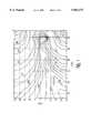
- FIG. 1is a plot useful for explaining the null characteristics of an in-phase transmitter loop.
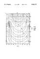
- FIG. 2is a plot useful for explaining the null characteristics of a "figure-8" transmitter loop.
- FIG. 3is a circuit schematic showing a transmitter-antenna system according to the inventive arrangements.
- FIGS. 5(a) and 5(b)are front perspective views of a transmitter loop arrangement, as mounted in a pylon, for in-phase and "figure-8" modes of operation.
- FIG. 1is a plot of vertical component field strength illustrating the coupling for the in-phase mode.
- FIG. 2is a plot of vertical component field strength illustrating the coupling for the "figure-8" mode. The vertical coupling is maximum at the center height, while two weak spots exist at heights about 20 inches lower and higher than the central line, which is well covered by the in-phase components.
- the transmittermust be tuned to provide sufficient current for proper operation. However, it has thus far been impossible to have the transmitter pair be in-tune for both in-phase and "figure-8" modes, due to existing mutual coupling of the two transmitter coils.
- the difference in resonant frequencies of the two transmitter phasestypically ranges between 3 kHz to 4 kHz. Therefore, maximum transmitter efficiency could not be achieved for both phases.
- the first stepis to tune the "figure-8" mode to resonate at the designated operating frequency, for example 58 kHz.
- the resonant frequency of the in-phase modeshifts upwardly to 61.3 kHz.
- a compensation coil or loop 16having one, two or a few turns can advantageously be wrapped around the outer perimeter of the pair of transmitter loops 12 and 14 and terminated with a capacitor. With a properly chosen capacitor value, the in-phase resonance can be adjusted back down to 58 kHz, due to the significant coupling between the compensation coil and the in-phase coil assemblies.
- the addition of the compensation loopdoes not affect the tuning of the "figure-8" mode because their mutual coupling is essentially zero. As a result, the modified coil assembly is tuned for both modes for maximum system detection.
- FIG. 3An exemplary transmitter-antenna circuit 10 in accordance with the inventive arrangements is shown in FIG. 3.
- Inductors L 1 and L 2represent the inductance of the two transmitter coils 12 and 14.
- Resistors R 1 and R 2represent the respective series resistances of the transmitter coils 12 and 14.
- the capacitors C 1 and C 2are used to tune the "figure-8" resonant frequency to the operating system frequency, for example 58 kHz.
- V S1 and R S1represent the output voltage and internal source resistance for one of the antenna drivers.
- V S2 and R S2represent the output voltage and internal source resistance for the other of the antenna drivers.
- the compensation loop or coil 16 needed for in-phase tuningis represented by inductor L c , resistor R c and capacitor C c .
- the coupling between the transmitter coils 12 and 14is represented by k 12 .
- the coupling between the compensation coil 16 and each of the transmitter coils 12 and 14is represented by k 1C and k 2C
Landscapes
- Engineering & Computer Science (AREA)
- Physics & Mathematics (AREA)
- Signal Processing (AREA)
- Automation & Control Theory (AREA)
- Computer Security & Cryptography (AREA)
- Electromagnetism (AREA)
- General Physics & Mathematics (AREA)
- Burglar Alarm Systems (AREA)
- Variable-Direction Aerials And Aerial Arrays (AREA)
- Near-Field Transmission Systems (AREA)
- Transmitters (AREA)
- Radar Systems Or Details Thereof (AREA)
Abstract
Description
TABLE 1______________________________________Transmitter LoopsR.sub.s1 L.sub.1 C.sub.1 R.sub.1 k.sub.12______________________________________1 Ω 350 μH 20 nF 2.96 Ω -0.053______________________________________
TABLE 2______________________________________Compensation CoilL.sub.c C.sub.c R.sub.c k.sub.1c,k2c______________________________________5.24 μH 390 nF 0.25 Ω 0.39______________________________________
TABLE 3______________________________________ Turns Ratio I.sub.1 (A) I.sub.2 (A) I.sub.c (A) (L.sub.1,2 /L.sub.c)______________________________________With compensation loop 8 8 18 15:1Without compensation loop 3.14 3.14 N/A 15:0______________________________________
Claims (19)
Priority Applications (8)
| Application Number | Priority Date | Filing Date | Title |
|---|---|---|---|
| US08/985,941US5963173A (en) | 1997-12-05 | 1997-12-05 | Antenna and transmitter arrangement for EAS system |
| BR9813377-2ABR9813377A (en) | 1997-12-05 | 1998-11-25 | Antenna and transmitter arrangement for eas system |
| CA002312929ACA2312929C (en) | 1997-12-05 | 1998-11-25 | Antenna and transmitter arrangement for eas system |
| PCT/US1998/025249WO1999030384A1 (en) | 1997-12-05 | 1998-11-25 | Antenna and transmitter arrangement for eas system |
| DE69841329TDE69841329D1 (en) | 1997-12-05 | 1998-11-25 | ANTENNA AND TRANSMITTER ARRANGEMENT FOR ELECTRONIC GOODS MONITORING SYSTEM |
| EP98965376AEP1036424B1 (en) | 1997-12-05 | 1998-11-25 | Antenna and transmitter arrangement for eas system |
| JP2000524837AJP4619532B2 (en) | 1997-12-05 | 1998-11-25 | Antenna and transmitter placement for EAM systems |
| AU20854/99AAU747534B2 (en) | 1997-12-05 | 1998-11-25 | Antenna and transmitter arrangement for EAS system |
Applications Claiming Priority (1)
| Application Number | Priority Date | Filing Date | Title |
|---|---|---|---|
| US08/985,941US5963173A (en) | 1997-12-05 | 1997-12-05 | Antenna and transmitter arrangement for EAS system |
Publications (1)
| Publication Number | Publication Date |
|---|---|
| US5963173Atrue US5963173A (en) | 1999-10-05 |
Family
ID=25531931
Family Applications (1)
| Application Number | Title | Priority Date | Filing Date |
|---|---|---|---|
| US08/985,941Expired - LifetimeUS5963173A (en) | 1997-12-05 | 1997-12-05 | Antenna and transmitter arrangement for EAS system |
Country Status (8)
| Country | Link |
|---|---|
| US (1) | US5963173A (en) |
| EP (1) | EP1036424B1 (en) |
| JP (1) | JP4619532B2 (en) |
| AU (1) | AU747534B2 (en) |
| BR (1) | BR9813377A (en) |
| CA (1) | CA2312929C (en) |
| DE (1) | DE69841329D1 (en) |
| WO (1) | WO1999030384A1 (en) |
Cited By (83)
| Publication number | Priority date | Publication date | Assignee | Title |
|---|---|---|---|---|
| WO2000026991A1 (en)* | 1998-11-04 | 2000-05-11 | Checkpoint Systems, Inc. | Rotating field antenna with a magnetically coupled quadrature loop |
| US6118378A (en)* | 1997-11-28 | 2000-09-12 | Sensormatic Electronics Corporation | Pulsed magnetic EAS system incorporating single antenna with independent phasing |
| US20020017336A1 (en)* | 2000-08-14 | 2002-02-14 | Gass Stephen F. | Apparatus and method for detecting dangerous conditions in power equipment |
| US20020017176A1 (en)* | 2000-08-14 | 2002-02-14 | Gass Stephen F. | Detection system for power equipment |
| US20020020265A1 (en)* | 2000-08-14 | 2002-02-21 | Gass Stephen F. | Translation stop for use in power equipment |
| US6388628B1 (en)* | 1998-05-18 | 2002-05-14 | Db Tag, Inc. | Systems and methods for wirelessly projecting power using in-phase current loops |
| US20020069734A1 (en)* | 2000-09-29 | 2002-06-13 | Gass Stephen F. | Contact detection system for power equipment |
| WO2003003323A1 (en)* | 2001-06-29 | 2003-01-09 | Sensormatic Electronics Corporation | Electronic article surveillance antenna for attachment to a vertical structure |
| US6567050B1 (en)* | 2001-12-17 | 2003-05-20 | Briggs James B | Loop antenna compensator |
| US6570541B2 (en) | 1998-05-18 | 2003-05-27 | Db Tag, Inc. | Systems and methods for wirelessly projecting power using multiple in-phase current loops |
| US20030112193A1 (en)* | 2001-12-17 | 2003-06-19 | Briggs James B. | Double loop antenna |
| US20030174099A1 (en)* | 2002-01-09 | 2003-09-18 | Westvaco Corporation | Intelligent station using multiple RF antennae and inventory control system and method incorporating same |
| US20030197652A1 (en)* | 2002-04-22 | 2003-10-23 | Wg Security Products, Inc. | Method and arrangement of antenna system of EAS |
| US20030216969A1 (en)* | 2002-01-23 | 2003-11-20 | Bauer Donald G. | Inventory management system |
| US6674365B2 (en)* | 2000-01-20 | 2004-01-06 | Skidata Ag | Communication terminal |
| US6680709B2 (en)* | 2001-02-09 | 2004-01-20 | Omron Corporation | Antenna apparatus |
| WO2003077364A3 (en)* | 2002-03-13 | 2004-03-11 | Gantle Trading & Services Lda | Antenna system for a transponder radio-frequency reading device |
| US6752837B2 (en) | 2002-06-28 | 2004-06-22 | Hewlett-Packard Development Company, L.P. | Security tags with a reversible optical indicator |
| US20040183742A1 (en)* | 2003-02-10 | 2004-09-23 | Goff Edward D. | Multi-loop antenna for radio frequency identification (RFID) communication |
| US6813983B2 (en) | 2000-09-29 | 2004-11-09 | Sd3, Llc | Power saw with improved safety system |
| US6826988B2 (en) | 2000-09-29 | 2004-12-07 | Sd3, Llc | Miter saw with improved safety system |
| US6857345B2 (en) | 2000-08-14 | 2005-02-22 | Sd3, Llc | Brake positioning system |
| EP1511121A1 (en)* | 2003-08-29 | 2005-03-02 | Seiko Epson Corporation | Loop antenna device |
| US6877410B2 (en) | 2000-09-29 | 2005-04-12 | Sd3, Llc | Miter saw with improved safety system |
| US6880440B2 (en) | 2000-09-29 | 2005-04-19 | Sd3, Llc | Miter saw with improved safety system |
| WO2005057725A1 (en)* | 2003-12-06 | 2005-06-23 | Telegesis (Uk) Ltd | Radio frequency antennae |
| US6920814B2 (en) | 2000-08-14 | 2005-07-26 | Sd3, Llc | Cutting tool safety system |
| US6945148B2 (en) | 2000-09-29 | 2005-09-20 | Sd3, Llc | Miter saw with improved safety system |
| US6945149B2 (en) | 2001-07-25 | 2005-09-20 | Sd3, Llc | Actuators for use in fast-acting safety systems |
| EP1596346A1 (en)* | 2004-05-11 | 2005-11-16 | Sensormatic Electronics Corporation | Closed loop transmitter control for power amplifier in an eas system |
| US6994004B2 (en) | 2000-09-29 | 2006-02-07 | Sd3, Llc | Table saw with improved safety system |
| US6997090B2 (en) | 2001-08-13 | 2006-02-14 | Sd3, Llc | Safety systems for power equipment |
| US7000514B2 (en) | 2001-07-27 | 2006-02-21 | Sd3, Llc | Safety systems for band saws |
| US7024975B2 (en) | 2000-08-14 | 2006-04-11 | Sd3, Llc | Brake mechanism for power equipment |
| US7055417B1 (en) | 1999-10-01 | 2006-06-06 | Sd3, Llc | Safety system for power equipment |
| US7077039B2 (en) | 2001-11-13 | 2006-07-18 | Sd3, Llc | Detection system for power equipment |
| EP1693778A1 (en)* | 2005-02-18 | 2006-08-23 | N.V. Nederlandsche Apparatenfabriek NEDAP | Shelf system having a label detecting system for reading out RFID labels |
| US7100483B2 (en) | 2000-08-14 | 2006-09-05 | Sd3, Llc | Firing subsystem for use in a fast-acting safety system |
| US20060202033A1 (en)* | 2005-03-03 | 2006-09-14 | Campero Richard J | Apparatus for and method of using an intelligent network and RFID signal router |
| US7137326B2 (en) | 2000-08-14 | 2006-11-21 | Sd3, Llc | Translation stop for use in power equipment |
| US7171879B2 (en) | 2001-07-02 | 2007-02-06 | Sd3, Llc | Discrete proximity detection system |
| US7197969B2 (en) | 2001-09-24 | 2007-04-03 | Sd3, Llc | Logic control with test mode for fast-acting safety system |
| US7225712B2 (en) | 2000-08-14 | 2007-06-05 | Sd3, Llc | Motion detecting system for use in a safety system for power equipment |
| US7231856B2 (en) | 2001-06-13 | 2007-06-19 | Sd3, Llc | Apparatus and method for detecting dangerous conditions in power equipment |
| US20070164845A1 (en)* | 2004-12-21 | 2007-07-19 | Checkpoint Systems, Inc. | System and method for monitoring security systems |
| US20070198720A1 (en)* | 2006-02-17 | 2007-08-23 | Neteffect, Inc. | Method and apparatus for a interfacing device drivers to a single multi-function adapter |
| US7290472B2 (en) | 2002-01-14 | 2007-11-06 | Sd3, Llc | Miter saw with improved safety system |
| US7308843B2 (en) | 2000-08-14 | 2007-12-18 | Sd3, Llc | Spring-biased brake mechanism for power equipment |
| US20070296548A1 (en)* | 2006-06-27 | 2007-12-27 | Hall Stewart E | Resonant circuit tuning system using magnetic field coupled reactive elements |
| US20070296593A1 (en)* | 2006-06-27 | 2007-12-27 | Hall Stewart E | Resonant circuit tuning system with dynamic impedance matching |
| US20080036590A1 (en)* | 2006-08-08 | 2008-02-14 | Ford Global Technologies, Llc | Sensor arrangement and method for using same |
| US7347851B1 (en) | 2004-03-09 | 2008-03-25 | Leo B Kriksunov | Needleless hypodermic jet injector apparatus and method |
| US7350445B2 (en) | 2003-08-20 | 2008-04-01 | Sd3, Llc | Brake cartridge for power equipment |
| US7350444B2 (en) | 2000-08-14 | 2008-04-01 | Sd3, Llc | Table saw with improved safety system |
| US7353737B2 (en) | 2001-08-13 | 2008-04-08 | Sd3, Llc | Miter saw with improved safety system |
| US7357056B2 (en) | 2000-09-29 | 2008-04-15 | Sd3, Llc | Cutting tool safety system |
| US7359174B2 (en) | 2000-08-14 | 2008-04-15 | Sd3, Llc | Motion detecting system for use in a safety system for power equipment |
| US7472634B2 (en) | 2003-08-20 | 2009-01-06 | Sd3, Llc | Woodworking machines with overmolded arbors |
| US7481140B2 (en) | 2005-04-15 | 2009-01-27 | Sd3, Llc | Detection systems for power equipment |
| US7536238B2 (en) | 2003-12-31 | 2009-05-19 | Sd3, Llc | Detection systems for power equipment |
| US7600455B2 (en) | 2000-08-14 | 2009-10-13 | Sd3, Llc | Logic control for fast-acting safety system |
| US7610836B2 (en) | 2000-08-14 | 2009-11-03 | Sd3, Llc | Replaceable brake mechanism for power equipment |
| US7621205B2 (en) | 1999-10-01 | 2009-11-24 | Sd3, Llc | Band saw with safety system |
| US7707920B2 (en) | 2003-12-31 | 2010-05-04 | Sd3, Llc | Table saws with safety systems |
| US7712403B2 (en) | 2001-07-03 | 2010-05-11 | Sd3, Llc | Actuators for use in fast-acting safety systems |
| US7784507B2 (en) | 2000-09-29 | 2010-08-31 | Sd3, Llc | Router with improved safety system |
| US7827890B2 (en) | 2004-01-29 | 2010-11-09 | Sd3, Llc | Table saws with safety systems and systems to mount and index attachments |
| US7836804B2 (en) | 2003-08-20 | 2010-11-23 | Sd3, Llc | Woodworking machines with overmolded arbors |
| US20110148588A1 (en)* | 2009-12-21 | 2011-06-23 | Comm. A L'ener. Atom. Et Aux Energies Alt. | Device for the secure contactless data exchange between a reader and a card |
| US20110205026A1 (en)* | 2009-10-09 | 2011-08-25 | Leigh Bateman | Radio frequency identification reader antenna having a dynamically adjustable q-factor |
| US20110210823A1 (en)* | 2009-10-09 | 2011-09-01 | Leigh Bateman | Hdx demodulator |
| US20110210824A1 (en)* | 2009-11-04 | 2011-09-01 | Allflex Usa, Inc. | Signal cancelling transmit/receive multi-loop antenna for a radio frequency identification reader |
| US20110269398A1 (en)* | 2009-06-16 | 2011-11-03 | B & Plus K.K. | Bidirectional transmission coil and bidirectional transmission system using the same |
| US8065943B2 (en) | 2000-09-18 | 2011-11-29 | Sd3, Llc | Translation stop for use in power equipment |
| US8100039B2 (en) | 2000-08-14 | 2012-01-24 | Sd3, Llc | Miter saw with safety system |
| US20120127035A1 (en)* | 2010-11-18 | 2012-05-24 | Wisconsin Alumni Research Foundation | Electrically small, source direction resolving antennas |
| US8459157B2 (en) | 2003-12-31 | 2013-06-11 | Sd3, Llc | Brake cartridges and mounting systems for brake cartridges |
| US8730044B2 (en) | 2002-01-09 | 2014-05-20 | Tyco Fire & Security Gmbh | Method of assigning and deducing the location of articles detected by multiple RFID antennae |
| US8849229B2 (en) | 2012-06-01 | 2014-09-30 | Wisconsin Alumni Research Foundation | Electrically small, super directive antennas |
| US20150090789A1 (en)* | 2012-01-05 | 2015-04-02 | Hid Global Gmbh | Calculated compensated magnetic antennas for different frequencies |
| US9424724B2 (en) | 2013-08-02 | 2016-08-23 | Bibliotheca Rfid Library Systems Ag | Single turn magnetic drive loop for electronic article surveillance |
| US9646239B2 (en) | 2008-09-04 | 2017-05-09 | Allflex Usa, Inc. | Combination full-duplex and half-duplex electronic identification tag |
| US9724840B2 (en) | 1999-10-01 | 2017-08-08 | Sd3, Llc | Safety systems for power equipment |
Families Citing this family (7)
| Publication number | Priority date | Publication date | Assignee | Title |
|---|---|---|---|---|
| GB9915595D0 (en)* | 1999-07-02 | 1999-09-01 | Sadler Robin W | Identification apparatus for reading moving tags in passageways |
| DE102007018059A1 (en)* | 2007-04-17 | 2008-10-23 | Kathrein-Werke Kg | RFID antenna system |
| DE102007018058A1 (en)* | 2007-04-17 | 2008-10-23 | Kathrein-Werke Kg | RFID antenna system |
| US7460073B2 (en) | 2007-04-18 | 2008-12-02 | Kathrein-Werke Kg | RFID antenna system |
| US7852268B2 (en) | 2007-04-18 | 2010-12-14 | Kathrein-Werke Kg | RFID antenna system |
| GB2461126B (en)* | 2008-06-25 | 2010-09-29 | Shearwell Data Ltd | Antenna system |
| US20120139730A1 (en)* | 2010-12-03 | 2012-06-07 | Metrologic Instruments, Inc. | Electronic article surveillance system |
Citations (12)
| Publication number | Priority date | Publication date | Assignee | Title |
|---|---|---|---|---|
| US3588905A (en)* | 1967-10-05 | 1971-06-28 | John H Dunlavy Jr | Wide range tunable transmitting loop antenna |
| US3683389A (en)* | 1971-01-20 | 1972-08-08 | Corning Glass Works | Omnidirectional loop antenna array |
| US4243980A (en)* | 1978-02-17 | 1981-01-06 | Lichtblau G J | Antenna system for electronic security installations |
| US4260990A (en)* | 1979-11-08 | 1981-04-07 | Lichtblau G J | Asymmetrical antennas for use in electronic security systems |
| US4658241A (en)* | 1985-09-17 | 1987-04-14 | Allied Corporation | Surveillance system including transmitter and receiver synchronized by power line zero crossings |
| US4675658A (en)* | 1985-09-17 | 1987-06-23 | Allied Corporation | System including tuned AC magnetic field transmit antenna and untuned AC magnetic field receive antenna |
| US4679046A (en)* | 1984-12-21 | 1987-07-07 | Senelco Limited | Transponder systems |
| US5023600A (en)* | 1990-04-10 | 1991-06-11 | Sensormatic Electronics Corporation | Electronic article surveillance system with adaptiveness for synchronization with companion systems |
| US5103234A (en)* | 1987-08-28 | 1992-04-07 | Sensormatic Electronics Corporation | Electronic article surveillance system |
| US5103235A (en)* | 1988-12-30 | 1992-04-07 | Checkpoint Systems, Inc. | Antenna structure for an electronic article surveillance system |
| US5353011A (en)* | 1993-01-04 | 1994-10-04 | Checkpoint Systems, Inc. | Electronic article security system with digital signal processing and increased detection range |
| US5663738A (en)* | 1993-07-13 | 1997-09-02 | Actron Entwicklungs Ag | Antenna device |
Family Cites Families (2)
| Publication number | Priority date | Publication date | Assignee | Title |
|---|---|---|---|---|
| US4647931A (en) | 1984-11-29 | 1987-03-03 | Rca Corporation | Dual frequency identification system |
| US5602556A (en)* | 1995-06-07 | 1997-02-11 | Check Point Systems, Inc. | Transmit and receive loop antenna |
- 1997
- 1997-12-05USUS08/985,941patent/US5963173A/ennot_activeExpired - Lifetime
- 1998
- 1998-11-25JPJP2000524837Apatent/JP4619532B2/ennot_activeExpired - Lifetime
- 1998-11-25CACA002312929Apatent/CA2312929C/ennot_activeExpired - Lifetime
- 1998-11-25DEDE69841329Tpatent/DE69841329D1/ennot_activeExpired - Lifetime
- 1998-11-25EPEP98965376Apatent/EP1036424B1/ennot_activeExpired - Lifetime
- 1998-11-25AUAU20854/99Apatent/AU747534B2/ennot_activeExpired
- 1998-11-25WOPCT/US1998/025249patent/WO1999030384A1/enactiveIP Right Grant
- 1998-11-25BRBR9813377-2Apatent/BR9813377A/ennot_activeIP Right Cessation
Patent Citations (12)
| Publication number | Priority date | Publication date | Assignee | Title |
|---|---|---|---|---|
| US3588905A (en)* | 1967-10-05 | 1971-06-28 | John H Dunlavy Jr | Wide range tunable transmitting loop antenna |
| US3683389A (en)* | 1971-01-20 | 1972-08-08 | Corning Glass Works | Omnidirectional loop antenna array |
| US4243980A (en)* | 1978-02-17 | 1981-01-06 | Lichtblau G J | Antenna system for electronic security installations |
| US4260990A (en)* | 1979-11-08 | 1981-04-07 | Lichtblau G J | Asymmetrical antennas for use in electronic security systems |
| US4679046A (en)* | 1984-12-21 | 1987-07-07 | Senelco Limited | Transponder systems |
| US4658241A (en)* | 1985-09-17 | 1987-04-14 | Allied Corporation | Surveillance system including transmitter and receiver synchronized by power line zero crossings |
| US4675658A (en)* | 1985-09-17 | 1987-06-23 | Allied Corporation | System including tuned AC magnetic field transmit antenna and untuned AC magnetic field receive antenna |
| US5103234A (en)* | 1987-08-28 | 1992-04-07 | Sensormatic Electronics Corporation | Electronic article surveillance system |
| US5103235A (en)* | 1988-12-30 | 1992-04-07 | Checkpoint Systems, Inc. | Antenna structure for an electronic article surveillance system |
| US5023600A (en)* | 1990-04-10 | 1991-06-11 | Sensormatic Electronics Corporation | Electronic article surveillance system with adaptiveness for synchronization with companion systems |
| US5353011A (en)* | 1993-01-04 | 1994-10-04 | Checkpoint Systems, Inc. | Electronic article security system with digital signal processing and increased detection range |
| US5663738A (en)* | 1993-07-13 | 1997-09-02 | Actron Entwicklungs Ag | Antenna device |
Cited By (155)
| Publication number | Priority date | Publication date | Assignee | Title |
|---|---|---|---|---|
| US6118378A (en)* | 1997-11-28 | 2000-09-12 | Sensormatic Electronics Corporation | Pulsed magnetic EAS system incorporating single antenna with independent phasing |
| US6388628B1 (en)* | 1998-05-18 | 2002-05-14 | Db Tag, Inc. | Systems and methods for wirelessly projecting power using in-phase current loops |
| US6570541B2 (en) | 1998-05-18 | 2003-05-27 | Db Tag, Inc. | Systems and methods for wirelessly projecting power using multiple in-phase current loops |
| US6166706A (en)* | 1998-11-04 | 2000-12-26 | Checkpoint Systems, Inc. | Rotating field antenna with a magnetically coupled quadrature loop |
| AU756531B2 (en)* | 1998-11-04 | 2003-01-16 | Checkpoint Systems, Inc. | Rotating field antenna with a magnetically coupled quadrature loop |
| WO2000026991A1 (en)* | 1998-11-04 | 2000-05-11 | Checkpoint Systems, Inc. | Rotating field antenna with a magnetically coupled quadrature loop |
| US9925683B2 (en) | 1999-10-01 | 2018-03-27 | Sawstop Holding Llc | Table saws |
| US9522476B2 (en) | 1999-10-01 | 2016-12-20 | Sd3, Llc | Power equipment with detection and reaction systems |
| US9969014B2 (en) | 1999-10-01 | 2018-05-15 | Sawstop Holding Llc | Power equipment with detection and reaction systems |
| US7347131B2 (en) | 1999-10-01 | 2008-03-25 | Sd3, Llc | Miter saw with improved safety system |
| US7895927B2 (en) | 1999-10-01 | 2011-03-01 | Sd3, Llc | Power equipment with detection and reaction systems |
| US7055417B1 (en) | 1999-10-01 | 2006-06-06 | Sd3, Llc | Safety system for power equipment |
| US9724840B2 (en) | 1999-10-01 | 2017-08-08 | Sd3, Llc | Safety systems for power equipment |
| US10335972B2 (en) | 1999-10-01 | 2019-07-02 | Sawstop Holding Llc | Table Saws |
| US7525055B2 (en) | 1999-10-01 | 2009-04-28 | Sd3, Llc | Switch box for power tools with safety systems |
| US7621205B2 (en) | 1999-10-01 | 2009-11-24 | Sd3, Llc | Band saw with safety system |
| US8408106B2 (en) | 1999-10-01 | 2013-04-02 | Sd3, Llc | Method of operating power equipment with detection and reaction systems |
| US7788999B2 (en) | 1999-10-01 | 2010-09-07 | Sd3, Llc | Brake mechanism for power equipment |
| US8196499B2 (en) | 1999-10-01 | 2012-06-12 | Sd3, Llc | Power equipment with detection and reaction systems |
| US6674365B2 (en)* | 2000-01-20 | 2004-01-06 | Skidata Ag | Communication terminal |
| US7359174B2 (en) | 2000-08-14 | 2008-04-15 | Sd3, Llc | Motion detecting system for use in a safety system for power equipment |
| US7100483B2 (en) | 2000-08-14 | 2006-09-05 | Sd3, Llc | Firing subsystem for use in a fast-acting safety system |
| US7137326B2 (en) | 2000-08-14 | 2006-11-21 | Sd3, Llc | Translation stop for use in power equipment |
| US7921754B2 (en) | 2000-08-14 | 2011-04-12 | Sd3, Llc | Logic control for fast-acting safety system |
| US8151675B2 (en) | 2000-08-14 | 2012-04-10 | Sd3, Llc | Logic control for fast-acting safety system |
| US7832314B2 (en) | 2000-08-14 | 2010-11-16 | Sd3, Llc | Brake positioning system |
| US8191450B2 (en) | 2000-08-14 | 2012-06-05 | Sd3, Llc | Power equipment with detection and reaction systems |
| US7681479B2 (en) | 2000-08-14 | 2010-03-23 | Sd3, Llc | Motion detecting system for use in a safety system for power equipment |
| US6857345B2 (en) | 2000-08-14 | 2005-02-22 | Sd3, Llc | Brake positioning system |
| US8522655B2 (en) | 2000-08-14 | 2013-09-03 | Sd3, Llc | Logic control for fast-acting safety system |
| US7610836B2 (en) | 2000-08-14 | 2009-11-03 | Sd3, Llc | Replaceable brake mechanism for power equipment |
| US7600455B2 (en) | 2000-08-14 | 2009-10-13 | Sd3, Llc | Logic control for fast-acting safety system |
| US9038515B2 (en) | 2000-08-14 | 2015-05-26 | Sd3, Llc | Logic control for fast-acting safety system |
| US8100039B2 (en) | 2000-08-14 | 2012-01-24 | Sd3, Llc | Miter saw with safety system |
| US6920814B2 (en) | 2000-08-14 | 2005-07-26 | Sd3, Llc | Cutting tool safety system |
| US20020020265A1 (en)* | 2000-08-14 | 2002-02-21 | Gass Stephen F. | Translation stop for use in power equipment |
| US7350444B2 (en) | 2000-08-14 | 2008-04-01 | Sd3, Llc | Table saw with improved safety system |
| US6957601B2 (en) | 2000-08-14 | 2005-10-25 | Sd3, Llc | Translation stop for use in power equipment |
| US20020017176A1 (en)* | 2000-08-14 | 2002-02-14 | Gass Stephen F. | Detection system for power equipment |
| US7308843B2 (en) | 2000-08-14 | 2007-12-18 | Sd3, Llc | Spring-biased brake mechanism for power equipment |
| US7284467B2 (en) | 2000-08-14 | 2007-10-23 | Sd3, Llc | Apparatus and method for detecting dangerous conditions in power equipment |
| US7228772B2 (en) | 2000-08-14 | 2007-06-12 | Sd3, Llc | Brake positioning system |
| US7024975B2 (en) | 2000-08-14 | 2006-04-11 | Sd3, Llc | Brake mechanism for power equipment |
| US20020017336A1 (en)* | 2000-08-14 | 2002-02-14 | Gass Stephen F. | Apparatus and method for detecting dangerous conditions in power equipment |
| US7225712B2 (en) | 2000-08-14 | 2007-06-05 | Sd3, Llc | Motion detecting system for use in a safety system for power equipment |
| US7210383B2 (en) | 2000-08-14 | 2007-05-01 | Sd3, Llc | Detection system for power equipment |
| US8065943B2 (en) | 2000-09-18 | 2011-11-29 | Sd3, Llc | Translation stop for use in power equipment |
| US7357056B2 (en) | 2000-09-29 | 2008-04-15 | Sd3, Llc | Cutting tool safety system |
| US6826988B2 (en) | 2000-09-29 | 2004-12-07 | Sd3, Llc | Miter saw with improved safety system |
| US20020069734A1 (en)* | 2000-09-29 | 2002-06-13 | Gass Stephen F. | Contact detection system for power equipment |
| US8186255B2 (en) | 2000-09-29 | 2012-05-29 | Sd3, Llc | Contact detection system for power equipment |
| US6880440B2 (en) | 2000-09-29 | 2005-04-19 | Sd3, Llc | Miter saw with improved safety system |
| US7784507B2 (en) | 2000-09-29 | 2010-08-31 | Sd3, Llc | Router with improved safety system |
| US6877410B2 (en) | 2000-09-29 | 2005-04-12 | Sd3, Llc | Miter saw with improved safety system |
| US6813983B2 (en) | 2000-09-29 | 2004-11-09 | Sd3, Llc | Power saw with improved safety system |
| US6994004B2 (en) | 2000-09-29 | 2006-02-07 | Sd3, Llc | Table saw with improved safety system |
| US7377199B2 (en) | 2000-09-29 | 2008-05-27 | Sd3, Llc | Contact detection system for power equipment |
| US6945148B2 (en) | 2000-09-29 | 2005-09-20 | Sd3, Llc | Miter saw with improved safety system |
| US8061245B2 (en) | 2000-09-29 | 2011-11-22 | Sd3, Llc | Safety methods for use in power equipment |
| US6680709B2 (en)* | 2001-02-09 | 2004-01-20 | Omron Corporation | Antenna apparatus |
| US9927796B2 (en) | 2001-05-17 | 2018-03-27 | Sawstop Holding Llc | Band saw with improved safety system |
| US7231856B2 (en) | 2001-06-13 | 2007-06-19 | Sd3, Llc | Apparatus and method for detecting dangerous conditions in power equipment |
| WO2003003323A1 (en)* | 2001-06-29 | 2003-01-09 | Sensormatic Electronics Corporation | Electronic article surveillance antenna for attachment to a vertical structure |
| US7171879B2 (en) | 2001-07-02 | 2007-02-06 | Sd3, Llc | Discrete proximity detection system |
| US7591210B2 (en) | 2001-07-02 | 2009-09-22 | Sd3, Llc | Discrete proximity detection system |
| US7712403B2 (en) | 2001-07-03 | 2010-05-11 | Sd3, Llc | Actuators for use in fast-acting safety systems |
| US6945149B2 (en) | 2001-07-25 | 2005-09-20 | Sd3, Llc | Actuators for use in fast-acting safety systems |
| US7000514B2 (en) | 2001-07-27 | 2006-02-21 | Sd3, Llc | Safety systems for band saws |
| US6997090B2 (en) | 2001-08-13 | 2006-02-14 | Sd3, Llc | Safety systems for power equipment |
| US7353737B2 (en) | 2001-08-13 | 2008-04-08 | Sd3, Llc | Miter saw with improved safety system |
| US7197969B2 (en) | 2001-09-24 | 2007-04-03 | Sd3, Llc | Logic control with test mode for fast-acting safety system |
| US7421315B2 (en) | 2001-11-13 | 2008-09-02 | Sd3, Llc | Detection system for power equipment |
| US7077039B2 (en) | 2001-11-13 | 2006-07-18 | Sd3, Llc | Detection system for power equipment |
| US6590542B1 (en)* | 2001-12-17 | 2003-07-08 | James B. Briggs | Double loop antenna |
| US6567050B1 (en)* | 2001-12-17 | 2003-05-20 | Briggs James B | Loop antenna compensator |
| US20030112193A1 (en)* | 2001-12-17 | 2003-06-19 | Briggs James B. | Double loop antenna |
| CN1639913B (en)* | 2002-01-09 | 2010-05-26 | Vue科技公司 | Intelligent station using multiple radio frequency antennas, inventory control system including the same, and inventory control method |
| US20030174099A1 (en)* | 2002-01-09 | 2003-09-18 | Westvaco Corporation | Intelligent station using multiple RF antennae and inventory control system and method incorporating same |
| US8730044B2 (en) | 2002-01-09 | 2014-05-20 | Tyco Fire & Security Gmbh | Method of assigning and deducing the location of articles detected by multiple RFID antennae |
| US20060238307A1 (en)* | 2002-01-09 | 2006-10-26 | Bauer Donald G | Intelligent station using multiple RF antennae and inventory control system and method incorporating same |
| WO2003061060A3 (en)* | 2002-01-09 | 2004-01-22 | Meadwestvaco Corp | Intelligent station using multiple rf antennae and inventory control system and method incorporating same |
| US20060232382A1 (en)* | 2002-01-09 | 2006-10-19 | Bauer Donald G | Intelligent station using multiple RF antennae and inventory control system and method incorporating same |
| WO2003061366A3 (en)* | 2002-01-09 | 2004-03-18 | Meadwestvaco Corp | Inventory management system |
| US7084769B2 (en) | 2002-01-09 | 2006-08-01 | Vue Technology, Inc. | Intelligent station using multiple RF antennae and inventory control system and method incorporating same |
| US7290472B2 (en) | 2002-01-14 | 2007-11-06 | Sd3, Llc | Miter saw with improved safety system |
| US20030216969A1 (en)* | 2002-01-23 | 2003-11-20 | Bauer Donald G. | Inventory management system |
| US8321302B2 (en) | 2002-01-23 | 2012-11-27 | Sensormatic Electronics, LLC | Inventory management system |
| WO2003077364A3 (en)* | 2002-03-13 | 2004-03-11 | Gantle Trading & Services Lda | Antenna system for a transponder radio-frequency reading device |
| WO2003090310A3 (en)* | 2002-04-22 | 2004-01-29 | Xiaohui Yang | Method and arrangement of antenna of eas |
| US20030197652A1 (en)* | 2002-04-22 | 2003-10-23 | Wg Security Products, Inc. | Method and arrangement of antenna system of EAS |
| US6753821B2 (en) | 2002-04-22 | 2004-06-22 | Wg Security Products, Inc. | Method and arrangement of antenna system of EAS |
| US6752837B2 (en) | 2002-06-28 | 2004-06-22 | Hewlett-Packard Development Company, L.P. | Security tags with a reversible optical indicator |
| US20040183742A1 (en)* | 2003-02-10 | 2004-09-23 | Goff Edward D. | Multi-loop antenna for radio frequency identification (RFID) communication |
| US7472634B2 (en) | 2003-08-20 | 2009-01-06 | Sd3, Llc | Woodworking machines with overmolded arbors |
| US7836804B2 (en) | 2003-08-20 | 2010-11-23 | Sd3, Llc | Woodworking machines with overmolded arbors |
| US7350445B2 (en) | 2003-08-20 | 2008-04-01 | Sd3, Llc | Brake cartridge for power equipment |
| EP1511121A1 (en)* | 2003-08-29 | 2005-03-02 | Seiko Epson Corporation | Loop antenna device |
| US7142163B2 (en) | 2003-08-29 | 2006-11-28 | Seiko Epson Corporation | Loop antenna device |
| US20050134519A1 (en)* | 2003-08-29 | 2005-06-23 | Seiko Epson Corporation | Loop antenna device |
| WO2005057725A1 (en)* | 2003-12-06 | 2005-06-23 | Telegesis (Uk) Ltd | Radio frequency antennae |
| US8122807B2 (en) | 2003-12-31 | 2012-02-28 | Sd3, Llc | Table saws with safety systems |
| US8087438B2 (en) | 2003-12-31 | 2012-01-03 | Sd3, Llc | Detection systems for power equipment |
| US7827893B2 (en) | 2003-12-31 | 2010-11-09 | Sd3, Llc | Elevation mechanism for table saws |
| US9623498B2 (en) | 2003-12-31 | 2017-04-18 | Sd3, Llc | Table saws |
| US8498732B2 (en) | 2003-12-31 | 2013-07-30 | Sd3, Llc | Detection systems for power equipment |
| US7866239B2 (en) | 2003-12-31 | 2011-01-11 | Sd3, Llc | Elevation mechanism for table saws |
| US20170312837A1 (en)* | 2003-12-31 | 2017-11-02 | Sd3, Llc | Table saws |
| US7707920B2 (en) | 2003-12-31 | 2010-05-04 | Sd3, Llc | Table saws with safety systems |
| US8489223B2 (en) | 2003-12-31 | 2013-07-16 | Sd3, Llc | Detection systems for power equipment |
| US8459157B2 (en) | 2003-12-31 | 2013-06-11 | Sd3, Llc | Brake cartridges and mounting systems for brake cartridges |
| US7991503B2 (en) | 2003-12-31 | 2011-08-02 | Sd3, Llc | Detection systems for power equipment |
| US10442108B2 (en)* | 2003-12-31 | 2019-10-15 | Sawstop Holding Llc | Table saws |
| US7536238B2 (en) | 2003-12-31 | 2009-05-19 | Sd3, Llc | Detection systems for power equipment |
| US7827890B2 (en) | 2004-01-29 | 2010-11-09 | Sd3, Llc | Table saws with safety systems and systems to mount and index attachments |
| US10882207B2 (en) | 2004-01-29 | 2021-01-05 | Sawstop Holding Llc | Table saws with safety systems and systems to mount and index attachments |
| US10052786B2 (en) | 2004-01-29 | 2018-08-21 | Sawstop Holding Llc | Table saws with safety systems and systems to mount and index attachments |
| US8505424B2 (en) | 2004-01-29 | 2013-08-13 | Sd3, Llc | Table saws with safety systems and systems to mount and index attachments |
| US7417599B2 (en)* | 2004-02-20 | 2008-08-26 | 3M Innovative Properties Company | Multi-loop antenna for radio frequency identification (RFID) communication |
| US7347851B1 (en) | 2004-03-09 | 2008-03-25 | Leo B Kriksunov | Needleless hypodermic jet injector apparatus and method |
| EP1596346A1 (en)* | 2004-05-11 | 2005-11-16 | Sensormatic Electronics Corporation | Closed loop transmitter control for power amplifier in an eas system |
| US20070164845A1 (en)* | 2004-12-21 | 2007-07-19 | Checkpoint Systems, Inc. | System and method for monitoring security systems |
| EP1693778A1 (en)* | 2005-02-18 | 2006-08-23 | N.V. Nederlandsche Apparatenfabriek NEDAP | Shelf system having a label detecting system for reading out RFID labels |
| US20060220875A1 (en)* | 2005-03-03 | 2006-10-05 | Campero Richard J | Apparatus for and method of using an intelligent network and RFID signal router |
| US20060220873A1 (en)* | 2005-03-03 | 2006-10-05 | Campero Richard J | Apparatus for and method of using an intelligent network and RFID signal router |
| US20060220876A1 (en)* | 2005-03-03 | 2006-10-05 | Campero Richard J | Apparatus for and method of using an intelligent network and RFID signal router |
| US7656858B2 (en) | 2005-03-03 | 2010-02-02 | Sensormatic Electronics, Llc. | Apparatus for and method of using an intelligent network and RFID signal router |
| US20060220874A1 (en)* | 2005-03-03 | 2006-10-05 | Campero Richard J | Apparatus for and method of using an intelligent network and RFID signal router |
| US20060202033A1 (en)* | 2005-03-03 | 2006-09-14 | Campero Richard J | Apparatus for and method of using an intelligent network and RFID signal router |
| US20060220862A1 (en)* | 2005-03-03 | 2006-10-05 | Campero Richard J | Apparatus for and method of using an intelligent network and RFID signal router |
| US7750812B2 (en) | 2005-03-03 | 2010-07-06 | Sensormatic Electronics, Llc. | Apparatus for and method of using an intelligent network and RFID signal router |
| US7481140B2 (en) | 2005-04-15 | 2009-01-27 | Sd3, Llc | Detection systems for power equipment |
| US20070198720A1 (en)* | 2006-02-17 | 2007-08-23 | Neteffect, Inc. | Method and apparatus for a interfacing device drivers to a single multi-function adapter |
| US20070296548A1 (en)* | 2006-06-27 | 2007-12-27 | Hall Stewart E | Resonant circuit tuning system using magnetic field coupled reactive elements |
| US20070296593A1 (en)* | 2006-06-27 | 2007-12-27 | Hall Stewart E | Resonant circuit tuning system with dynamic impedance matching |
| US7570220B2 (en) | 2006-06-27 | 2009-08-04 | Sensormatic Electronics Corporation | Resonant circuit tuning system with dynamic impedance matching |
| US7954995B2 (en) | 2006-08-08 | 2011-06-07 | Ford Global Technologies, Llc | Sensor arrangement and method for using same |
| US7651267B2 (en) | 2006-08-08 | 2010-01-26 | Ford Global Technologies, Llc | Sensor arrangement and method for using same |
| US20100080263A1 (en)* | 2006-08-08 | 2010-04-01 | Ford Global Technologies, Llc | Sensor Arrangement And Method For Using Same |
| US20080036590A1 (en)* | 2006-08-08 | 2008-02-14 | Ford Global Technologies, Llc | Sensor arrangement and method for using same |
| US9646239B2 (en) | 2008-09-04 | 2017-05-09 | Allflex Usa, Inc. | Combination full-duplex and half-duplex electronic identification tag |
| US8422973B2 (en)* | 2009-06-16 | 2013-04-16 | B & Plus K.K. | Bidirectional transmission coil and bidirectional transmission system using the same |
| US20110269398A1 (en)* | 2009-06-16 | 2011-11-03 | B & Plus K.K. | Bidirectional transmission coil and bidirectional transmission system using the same |
| US8493185B2 (en) | 2009-10-09 | 2013-07-23 | Aleis Pty Ltd | Radio frequency identification reader antenna having a dynamically adjustable Q-factor |
| US8811542B2 (en) | 2009-10-09 | 2014-08-19 | Aleis Pty Ltd. | HDX demodulator |
| US20110210823A1 (en)* | 2009-10-09 | 2011-09-01 | Leigh Bateman | Hdx demodulator |
| US20110205026A1 (en)* | 2009-10-09 | 2011-08-25 | Leigh Bateman | Radio frequency identification reader antenna having a dynamically adjustable q-factor |
| US8854188B2 (en) | 2009-11-04 | 2014-10-07 | Allflex Usa, Inc. | Signal cancelling transmit/receive multi-loop antenna for a radio frequency identification reader |
| US20110210824A1 (en)* | 2009-11-04 | 2011-09-01 | Allflex Usa, Inc. | Signal cancelling transmit/receive multi-loop antenna for a radio frequency identification reader |
| US8773241B2 (en)* | 2009-12-21 | 2014-07-08 | Commissariat à l'énergie atomique et aux énergies alternatives | Device for the secure contactless data exchange between a reader and a card |
| US20110148588A1 (en)* | 2009-12-21 | 2011-06-23 | Comm. A L'ener. Atom. Et Aux Energies Alt. | Device for the secure contactless data exchange between a reader and a card |
| US8362956B2 (en)* | 2010-11-18 | 2013-01-29 | Nader Behdad | Electrically small, source direction resolving antennas |
| US20120127035A1 (en)* | 2010-11-18 | 2012-05-24 | Wisconsin Alumni Research Foundation | Electrically small, source direction resolving antennas |
| US20150090789A1 (en)* | 2012-01-05 | 2015-04-02 | Hid Global Gmbh | Calculated compensated magnetic antennas for different frequencies |
| US8849229B2 (en) | 2012-06-01 | 2014-09-30 | Wisconsin Alumni Research Foundation | Electrically small, super directive antennas |
| US9424724B2 (en) | 2013-08-02 | 2016-08-23 | Bibliotheca Rfid Library Systems Ag | Single turn magnetic drive loop for electronic article surveillance |
Also Published As
| Publication number | Publication date |
|---|---|
| AU2085499A (en) | 1999-06-28 |
| DE69841329D1 (en) | 2010-01-07 |
| JP2001526480A (en) | 2001-12-18 |
| BR9813377A (en) | 2000-10-10 |
| EP1036424A1 (en) | 2000-09-20 |
| AU747534B2 (en) | 2002-05-16 |
| CA2312929A1 (en) | 1999-06-17 |
| EP1036424B1 (en) | 2009-11-25 |
| WO1999030384A1 (en) | 1999-06-17 |
| CA2312929C (en) | 2006-07-11 |
| EP1036424A4 (en) | 2001-01-24 |
| JP4619532B2 (en) | 2011-01-26 |
Similar Documents
| Publication | Publication Date | Title |
|---|---|---|
| US5963173A (en) | Antenna and transmitter arrangement for EAS system | |
| CA2470428C (en) | Antenna system including simultaneous phase aiding and phase canceling elements | |
| US5373301A (en) | Transmit and receive antenna having angled crossover elements | |
| US6166706A (en) | Rotating field antenna with a magnetically coupled quadrature loop | |
| US6118378A (en) | Pulsed magnetic EAS system incorporating single antenna with independent phasing | |
| AU694881B2 (en) | Transmit and receive loop antenna | |
| US6753821B2 (en) | Method and arrangement of antenna system of EAS | |
| EP1846984A2 (en) | Core antenna for eas and rfid applications | |
| JPH0756946B2 (en) | Signal receiving device and antenna from passive transponder | |
| EP0704928A3 (en) | RF transponder system with parallel resonant interrogation and series resonant response | |
| US9257025B2 (en) | Method to drive an antenna coil maintaining limited power source output | |
| US8451126B2 (en) | Combination electronic article surveillance/radio frequency identification antenna and method | |
| US7154447B2 (en) | Nanocrystalline core antenna for EAS and RFID applications | |
| EP1128464B1 (en) | Antenna of an electromagnetic detection system, and electromagnetic detection system comprising such antenna | |
| FI79625B (en) | KORSSTRAOLANDE HOEGFREKVENT STOELDFOERHINDRANDE SYSTEM. | |
| HK1074113A (en) | Antenna system including simultaneous phase aiding and phase canceling element |
Legal Events
| Date | Code | Title | Description |
|---|---|---|---|
| AS | Assignment | Owner name:SENSORMATIC ELECTRONICS CORPORATION, FLORIDA Free format text:ASSIGNMENT OF ASSIGNORS INTEREST;ASSIGNOR:SOLASKI, THOMAS P.;REEL/FRAME:008898/0194 Effective date:19971201 Owner name:SENSORMATIC ELECTRONICS CORPORATION, FLORIDA Free format text:ASSIGNMENT OF ASSIGNORS INTEREST;ASSIGNOR:LIAN, MING-REN;REEL/FRAME:008898/0111 Effective date:19971201 | |
| STCF | Information on status: patent grant | Free format text:PATENTED CASE | |
| AS | Assignment | Owner name:SENSORMATIC ELECTRONICS CORPORATION, FLORIDA Free format text:MERGER/CHANGE OF NAME;ASSIGNOR:SENSORMATIC ELECTRONICS CORPORATION;REEL/FRAME:012991/0641 Effective date:20011113 | |
| FEPP | Fee payment procedure | Free format text:PAYOR NUMBER ASSIGNED (ORIGINAL EVENT CODE: ASPN); ENTITY STATUS OF PATENT OWNER: LARGE ENTITY | |
| FPAY | Fee payment | Year of fee payment:4 | |
| FPAY | Fee payment | Year of fee payment:8 | |
| AS | Assignment | Owner name:SENSORMATIC ELECTRONICS, LLC,FLORIDA Free format text:MERGER;ASSIGNOR:SENSORMATIC ELECTRONICS CORPORATION;REEL/FRAME:024213/0049 Effective date:20090922 Owner name:SENSORMATIC ELECTRONICS, LLC, FLORIDA Free format text:MERGER;ASSIGNOR:SENSORMATIC ELECTRONICS CORPORATION;REEL/FRAME:024213/0049 Effective date:20090922 | |
| FPAY | Fee payment | Year of fee payment:12 | |
| AS | Assignment | Owner name:ADT SERVICES GMBH, SWITZERLAND Free format text:ASSIGNMENT OF ASSIGNORS INTEREST;ASSIGNOR:SENSORMATIC ELECTRONICS, LLC;REEL/FRAME:029894/0856 Effective date:20130214 | |
| AS | Assignment | Owner name:TYCO FIRE & SECURITY GMBH, SWITZERLAND Free format text:MERGER;ASSIGNOR:ADT SERVICES GMBH;REEL/FRAME:030290/0731 Effective date:20130326 |