US5963166A - Precise spacecraft camera image navigation and registration - Google Patents
Precise spacecraft camera image navigation and registrationDownload PDFInfo
- Publication number
- US5963166A US5963166AUS09/121,507US12150798AUS5963166AUS 5963166 AUS5963166 AUS 5963166AUS 12150798 AUS12150798 AUS 12150798AUS 5963166 AUS5963166 AUS 5963166A
- Authority
- US
- United States
- Prior art keywords
- camera
- spacecraft
- orbit
- attitude
- precise
- Prior art date
- Legal status (The legal status is an assumption and is not a legal conclusion. Google has not performed a legal analysis and makes no representation as to the accuracy of the status listed.)
- Expired - Lifetime
Links
Images


Classifications
- G—PHYSICS
- G01—MEASURING; TESTING
- G01S—RADIO DIRECTION-FINDING; RADIO NAVIGATION; DETERMINING DISTANCE OR VELOCITY BY USE OF RADIO WAVES; LOCATING OR PRESENCE-DETECTING BY USE OF THE REFLECTION OR RERADIATION OF RADIO WAVES; ANALOGOUS ARRANGEMENTS USING OTHER WAVES
- G01S5/00—Position-fixing by co-ordinating two or more direction or position line determinations; Position-fixing by co-ordinating two or more distance determinations
- G01S5/02—Position-fixing by co-ordinating two or more direction or position line determinations; Position-fixing by co-ordinating two or more distance determinations using radio waves
- G01S5/0247—Determining attitude
- B—PERFORMING OPERATIONS; TRANSPORTING
- B64—AIRCRAFT; AVIATION; COSMONAUTICS
- B64G—COSMONAUTICS; VEHICLES OR EQUIPMENT THEREFOR
- B64G1/00—Cosmonautic vehicles
- B64G1/22—Parts of, or equipment specially adapted for fitting in or to, cosmonautic vehicles
- B64G1/24—Guiding or controlling apparatus, e.g. for attitude control
- B64G1/244—Spacecraft control systems
- B—PERFORMING OPERATIONS; TRANSPORTING
- B64—AIRCRAFT; AVIATION; COSMONAUTICS
- B64G—COSMONAUTICS; VEHICLES OR EQUIPMENT THEREFOR
- B64G1/00—Cosmonautic vehicles
- B64G1/22—Parts of, or equipment specially adapted for fitting in or to, cosmonautic vehicles
- B64G1/24—Guiding or controlling apparatus, e.g. for attitude control
- B64G1/28—Guiding or controlling apparatus, e.g. for attitude control using inertia or gyro effect
- B—PERFORMING OPERATIONS; TRANSPORTING
- B64—AIRCRAFT; AVIATION; COSMONAUTICS
- B64G—COSMONAUTICS; VEHICLES OR EQUIPMENT THEREFOR
- B64G1/00—Cosmonautic vehicles
- B64G1/22—Parts of, or equipment specially adapted for fitting in or to, cosmonautic vehicles
- B64G1/24—Guiding or controlling apparatus, e.g. for attitude control
- B64G1/36—Guiding or controlling apparatus, e.g. for attitude control using sensors, e.g. sun-sensors, horizon sensors
- B64G1/361—Guiding or controlling apparatus, e.g. for attitude control using sensors, e.g. sun-sensors, horizon sensors using star sensors
- B—PERFORMING OPERATIONS; TRANSPORTING
- B64—AIRCRAFT; AVIATION; COSMONAUTICS
- B64G—COSMONAUTICS; VEHICLES OR EQUIPMENT THEREFOR
- B64G1/00—Cosmonautic vehicles
- B64G1/22—Parts of, or equipment specially adapted for fitting in or to, cosmonautic vehicles
- B64G1/24—Guiding or controlling apparatus, e.g. for attitude control
- B64G1/36—Guiding or controlling apparatus, e.g. for attitude control using sensors, e.g. sun-sensors, horizon sensors
- B64G1/365—Guiding or controlling apparatus, e.g. for attitude control using sensors, e.g. sun-sensors, horizon sensors using horizon or Earth sensors
- B—PERFORMING OPERATIONS; TRANSPORTING
- B64—AIRCRAFT; AVIATION; COSMONAUTICS
- B64G—COSMONAUTICS; VEHICLES OR EQUIPMENT THEREFOR
- B64G1/00—Cosmonautic vehicles
- B64G1/22—Parts of, or equipment specially adapted for fitting in or to, cosmonautic vehicles
- B64G1/24—Guiding or controlling apparatus, e.g. for attitude control
- B64G1/36—Guiding or controlling apparatus, e.g. for attitude control using sensors, e.g. sun-sensors, horizon sensors
- B64G1/369—Guiding or controlling apparatus, e.g. for attitude control using sensors, e.g. sun-sensors, horizon sensors using gyroscopes as attitude sensors
- B—PERFORMING OPERATIONS; TRANSPORTING
- B64—AIRCRAFT; AVIATION; COSMONAUTICS
- B64G—COSMONAUTICS; VEHICLES OR EQUIPMENT THEREFOR
- B64G1/00—Cosmonautic vehicles
- B64G1/22—Parts of, or equipment specially adapted for fitting in or to, cosmonautic vehicles
- B64G1/66—Arrangements or adaptations of apparatus or instruments, not otherwise provided for
- B—PERFORMING OPERATIONS; TRANSPORTING
- B64—AIRCRAFT; AVIATION; COSMONAUTICS
- B64G—COSMONAUTICS; VEHICLES OR EQUIPMENT THEREFOR
- B64G3/00—Observing or tracking cosmonautic vehicles
- B—PERFORMING OPERATIONS; TRANSPORTING
- B64—AIRCRAFT; AVIATION; COSMONAUTICS
- B64G—COSMONAUTICS; VEHICLES OR EQUIPMENT THEREFOR
- B64G1/00—Cosmonautic vehicles
- B64G1/22—Parts of, or equipment specially adapted for fitting in or to, cosmonautic vehicles
- B64G1/24—Guiding or controlling apparatus, e.g. for attitude control
- B64G1/26—Guiding or controlling apparatus, e.g. for attitude control using jets
- B—PERFORMING OPERATIONS; TRANSPORTING
- B64—AIRCRAFT; AVIATION; COSMONAUTICS
- B64G—COSMONAUTICS; VEHICLES OR EQUIPMENT THEREFOR
- B64G1/00—Cosmonautic vehicles
- B64G1/22—Parts of, or equipment specially adapted for fitting in or to, cosmonautic vehicles
- B64G1/24—Guiding or controlling apparatus, e.g. for attitude control
- B64G1/28—Guiding or controlling apparatus, e.g. for attitude control using inertia or gyro effect
- B64G1/285—Guiding or controlling apparatus, e.g. for attitude control using inertia or gyro effect using momentum wheels
Definitions
- the present inventionrelates generally to satellite-based imaging systems that are used to observe and predict weather patterns, and more particularly, to a satellite-based imaging system that provides improved weather prediction capability and simplified ground operations.
- the assignee of the present inventionhas developed and deployed a geostationary operational environmental satellite (GOES I-M) that contains an imaging system that operates in both the visible and infrared regions of the spectrum and generates digitized images of the Earth.
- GOES I-Mgeostationary operational environmental satellite
- the digitized images generated by the imaging systemare used for a variety of purposes, including weather prediction, monitoring and analyzing flash floods, and determining wind velocity by tracking cloud motion, for example.
- the present inventionprovides for an improved system that includes a spacecraft- or satellite-based imaging system and ground support and processing equipment that may be used for weather prediction purposes.
- the present inventionincludes numerous aspects that improve the imaging camera pointing accuracy and simplify ground-based operations.
- the present inventionprovides for a precise, spacecraft camera image navigation and registration system and method wherein a computer on-board the spacecraft and a ground system precisely compute image navigation and registration data from precise data measurements.
- a spacecraft control system(the on-board computer) uses precise star tracker, gyro, and earth sensor attitude data to precisely point the spacecraft and the camera.
- the ground systemutilizes precise star measurement data from the camera and range data from two ground stations time tagged with GPS precise clock data.
- the ground systemuses these precise measurements to determine precise orbit and attitude coefficients and uploads these coefficients to the spacecraft.
- the computer on-board the spacecraftuses these precise coefficients to generate and apply precise signals to compensate for slow orbit and attitude variations and register camera images in real time.
- the computer on-board the spacecraftis also used to generate camera commands to eliminate the need to upload a large number of daily ground commands, which therefore simplifies ground operations.
- the systemcomprises a spacecraft having an imaging system, and ground-based equipment that communicates with the spacecraft.
- the imaging systemtypically comprises a plurality of cameras, including an imager and a sounder (i.e., cameras) that are each coupled to thermal coolers. The pointing directions of the imager and sounder are controlled by gimbaled mirrors.
- the spacecraftalso comprises a plurality of pulsed plasma thrusters, a plurality of momentum wheels, a plurality of earth sensors, a plurality of gyros, and a plurality of star trackers.
- the ground-based equipmentprocesses downloaded image data derived from the imager and the sounder and uploads coefficients for image motion compensation.
- An on-board computercomprising attitude control electronics uses the uploaded coefficients to compute the camera attitude and spacecraft orbital elements as a function of time.
- the on-board computeralso generates image motion compensation signals to precisely adjust pointing of the image and sounder mirrors.
- the present inventionprovides for substantially reduced thermal backloading on the thermal coolers used by the imager and sounder by eliminating the use of the solar sail and boom employed on previous spacecraft.
- This aspectproduces zero thermal backloading on the imager and sounder thermal coolers, resulting in a higher signal-to-noise ratio for infrared (IR) data derived from the imager and sounder.
- IRinfrared
- the present inventionuses pulsed plasma thrusters which imparts a minimal number of momentum changes and dynamic disturbances to the spacecraft.
- the pulsed plasma thrustersin combination with the star trackers, four momentum wheels, and inertial reference units (gyros) provide for continuous, precise image navigation and registration. This also eliminates housekeeping intervals, thereby allowing continuous imaging and sounding by the imaging system, and provides system robustness against momentum wheel failures. Housekeeping refers to times when the thrusters are fired for purposes of attitude control or momentum dumping.
- the attitude control electronics(or attitude control electronics computer) on-board the spacecraft provides autonomous command capability. Autonomous imaging system operation is provided using less than 50 commands per day versus 3,500 for the previously deployed GOES I-M system. Furthermore, weekly uploads of image motion compensation (IMC) data are sent to the attitude control electronics instead of daily IMC data uploads to the GOES I-M system.
- IMCimage motion compensation
- auxiliary ranging stationprovides for greatly improved orbit determination (150 meters vs. 1000 meters) for star tracker operation.
- the ranging systems employed in the auxiliary ranging station and the command and data acquisition stationare used in conjunction with the orbit and attitude tracking system in the command and data acquisition station to determine the orbit position of the spacecraft to less than 150 meters (4 ⁇ rad).
- the ranging systemsuse GPS timing information to substantially eliminate orbit position error as a source of image navigation and registration error.
- the auxiliary ranging stationalso provides orbit information for star tracker operation, and sounder navigation and registration in case of imager failure.
- the present inventionsimplifies ground operations required to process data received from the spacecraft and upload data to control the spacecraft and cameras.
- the use of the star trackersreduces uploading of image motion compensation coefficients from the command and data acquisition station.
- the image motion compensation coefficientsare uploaded once a week to provide for fixed gridding of the camera images (i.e., maintain the image points, or grid, corresponding to geographical boundaries, fixed regardless of time).
- the use of the auxiliary ranging stationeliminates the need for imaging processing to locate landmarks to determine the orbit of the spacecraft.
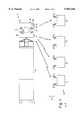
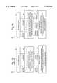
- FIG. 1illustrates the architecture of a geostationary operational environmental satellite (GOES) imaging system in accordance with the principles of the present invention
- FIG. 2illustrates details of ground-based equipment employed in the imaging system of the present invention
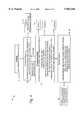
- FIG. 3illustrates processing performed by the imaging system of the present invention that provides for improved weather prediction accuracy
- FIG. 4is a simplified block diagram that illustrates various features of the system that implement various aspects of the present invention.
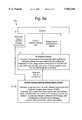
- FIG. 5aillustrates orbit and attitude processing performed by a prior art embodiment of a satellite based imaging system
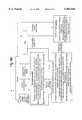
- FIG. 5billustrates orbit and attitude processing performed by an embodiment of the present satellite based imaging system
- FIG. 6aillustrates image motion compensation processing performed by a prior art embodiment of a satellite based imaging system
- FIG. 6billustrates image motion compensation processing performed by an embodiment of the present satellite based imaging system
- FIG. 7aillustrates camera command processing performed by a prior art embodiment of a satellite based imaging system
- FIG. 7billustrates camera command processing performed by an embodiment of the present satellite based imaging system.
- FIG. 1is a block diagram illustrating the architecture of a geostationary operational environmental satellite (GOES) imaging system 10 in accordance with the principles of the present invention.
- the GOES imaging system 10includes a space-based segment 11 comprising a spacecraft 20 or satellite 20, and a ground segment 12 comprising ground-based equipment 12.
- the spacecraft 20includes the imaging system 10 which typically comprises an imager 34 and a sounder 34 (i.e., cameras 34), which generate images using steerable (controllable) pointing mirrors 34i a, and attitude control electronics (ACE) 36 (or attitude control electronics computer 36) that controls the spacecraft 20 and generates image motion compensation signals to adjust pointing of the cameras 34.
- the imager 34is a camera 34 that provides multispectral radiometric imaging of the surface of a central body, such as Earth.
- the sounder 34is a camera that measures moisture content and temperature within he earth's atmosphere on a pixel-by-pixel basis.
- the imager 34 and sounder 34use the controllable pointing mirror 34a to produce images of the Earth.
- attitude control electronics 36 and the cameras 34are generally described in documents entitled "Geostationary Operational Environmental Satellite, GOES I-M System Description", by John Savides, Space Systems/Loral, December, 1992 and "GOES I-M System Databook", Space Systems/Loral, DRL 101-08.
- the image motion compensation performed in the attitude control electronics computer 36compensates for deterministic long-term orbit and attitude deviations from ideal synchronous orbit and zero attitude using ground-supplied image notion compensation coefficients.
- the attitude control electronics 36implements an image motion compensation algorithm that provides images registered at the source (without resampling). In other words, the image motion compensation algorithm registers the respective images produced by the camera 34 in real time by adjusting the camera pointing to compensate for the camera drift relative to the central body (Earth).
- the spacecraft 20uses four momentum wheels 31, two inertial reference units 32 (gyros 32), and three star trackers 33.
- the inertial reference units 32 or gyros 32 and star trackers 33provide continuous attitude-sensing. Signals derived from the momentum wheels 31, the gyros 32 and the star trackers 33 are processed to provide continuous, precise image navigation and registration.
- Earth sensors 37are used as a backup for the star trackers 33. The use of the backup Earth sensors 37 mitigates the risk of on-orbit anomalies caused by problems with the star trackers 33.
- the command and data acquisition station 41comprises one or more antennas 45 that are used to communicate with the spacecraft 20.
- the antenna(s) 45is (are) coupled to radio frequency (RF) equipment 51 that is coupled to a ranging system 53, a multiuse data link (MDL) receive server and processing (MRSP) system 54 and a telemetry acquisition and command transition system (NTACTS) 57.
- RFradio frequency
- the MDL receive server and processing system 54 and the telemetry acquisition and command transition system 57are coupled to a GOES telemetry and command system (GTACS) 55.
- GTACSGOES telemetry and command system
- the GOES telemetry and command system 55is coupled to an orbit and attitude tracking system (OATS) 56 and to a sensor processing system (SPS) 58.
- SPSsensor processing system
- a product monitor (PM) 59is coupled to the sensor processing system 58.
- the orbit and attitude tracking system 56interfaces with the spacecraft 20 to correct (adjust) the line of sight of the pointing mirrors 34a used by the imager 34 and sounder 34. Details of the orbit and attitude tracking system 56 are generally well known, and may be found in U.S. Pat. No. 4,688,092, the contents of which are incorporated herein by reference.
- a global positioning system (GPS) timing system 52is coupled to the ranging system 53 and receives timing signals from a global positioning system satellite 60.
- the imagery data including a range wordis uplinked from the ground station 41 to the spacecraft 20. This data is then downlinked from the satellite 20 to the ranging system 53.
- the ranging system 53extracts the range word and uses the GPS precision timing data to indicate the precise time of receipt of the range word transmitted from the spacecraft 20.
- the GOES telemetry and command system 55is coupled to an orbit and attitude tracking system 56 and to the product monitor 59.
- the GOES telemetry and command system 55is coupled to the sensor processing system 58 of both the command and data acquisition station 41 and the backup command and data acquisition station 43.
- the GOES telemetry and command system 55is also coupled to the telemetry acquisition and command transition system 57 of both the command and data acquisition station 41 and the backup command and data acquisition station 43.
- the auxiliary ranging system 44comprises one or more antennas 45 that are used to communicate with the spacecraft 20.
- the antenna(s) 45is (are) coupled to radio frequency (RF) equipment 51 that is coupled to a ranging system 53.
- RFradio frequency
- a GPS timing system 52is coupled to the ranging system 53 and receives timing signals from a global positioning system satellite.
- the GPS timing system 52generates range word time tags that are sent to the orbit and attitude tracking system 56.
- Range data in a GOES variable data format (GVAR)is downlinked from the spacecraft 20 to the ranging system 53.
- GVARGOES variable data format
- the imager 34 and the sounder 34 transmit star position dataare processed by the various orbit and attitude tracking systems 56 to compute image motion compensation coefficients that are sent to the attitude control electronics 36.
- the ground equipment 12uploads the image motion compensation coefficients to the attitude control electronics 36 in the spacecraft 20.
- the attitude control electronics 36processes image motion compensation coefficients received from the ground equipment 12 and generates image motion compensation signals in the form of mirror pointing commands (gimbal angle corrections).
- the mirror pointing commandsare sent to the imager 34 and the sounder 34 which process them to adjust the pointing direction of the pointing mirrors 34a.
- the imager 34 and the sounder 34output raw data (comprising imagery data, star data, and gimbal angles) that are transmitted to the sensor processing system 58.
- the sensor processing system 58process the raw data and outputs imager and sounder star measurements and CDA range measurements to the orbit and attitude tracking system 56.
- the product monitor 59processes GOES variable data format image data to produce imager landmark measurements that are sent to the orbit and attitude tracking system 56.
- the auxiliary ranging system (ARS) 44outputs ARS measurements and an ARS time reference to the orbit and attitude tracking system 56.
- the orbit and attitude tracking system 56processes the ARS measurements, ARS time reference, imager landmark measurements imager and sounder star measurements and CDA range measurements to generate image motion compensation data and user navigation data.
- the image motion compensation dataare sent to the GOES telemetry and command system (GTACS) 55 which generates image motion compensation coefficients.
- the image motion compensation coefficientsare uploaded once per week to the attitude control electronics 36 in the spacecraft 20.
- the image motion compensation coefficientsare processed by the attitude control electronics 36 to generate gimbal angle corrections which adjust the pointing direction of the pointing mirrors 34a.
- the user navigation datais sent to the sensor processing system 58 and is included in GVAR data.
- High frequency (>1 Hz) attitude disturbancesare minimized by design. This includes the effect of momentum wheel imbalance and solar array stepping.
- the response of the spacecraft 20 to high frequency disturbancesis ⁇ 5 ⁇ rad.
- Low frequency ( ⁇ 0.01 Hz) attitude disturbancesare controlled using data from the star trackers 33 and inertial reference units 32. Residual error in this frequency range is ⁇ 2 ⁇ rad.
- Medium frequency (0.01-1.0 Hz) attitude disturbancesare compensated for by the attitude control electronics 36 using data from the star trackers 33 and inertial reference units 32.
- the residual error after spacecraft motion compensationis ⁇ 3 ⁇ rad.
- the auxiliary ranging system (ARS) 44acquires auxiliary ranging data from the command and data acquisition station 41 and one remote location. This capability virtually eliminates the orbit determination error and allows weekly, instead of daily, orbit and attitude determination. Auxiliary ranging station data also provides quick orbit recovery after a stationkeeping. The use of the auxiliary ranging station 44 potentially eliminates the use of landmarks in the orbit and attitude determination process.
- the orbit and attitude tracking system 56determines the orbit from range only and determines attitude from star measurements made by the imager 34 and the sounder 34. Landmarks are only used to verify imager image navigation and registration performance.
- the present image navigation and registration system 10eliminates the GOES I-M short span attitude adjustments that are required every few hours over the spacecraft lifetime. Therefore, the present invention thus simplifies the spacecraft control center 42 operations and improves performance. Image motion compensation orbit-model coefficients have been increased from 24 (used in the GOES I-M system) to 43 to minimize orbit-prediction error over one week.
- a GPS receiver (not shown) in the auxiliary ranging station 44is used to provide this precise time tag and to precisely synchronize clocks at the two ranging locations.
- the attitude control systemprocesses data from the star tracker, 33 and gyros 32 to precisely and continuously sense spacecraft attitude and eliminate short span attitude adjustment operations at the spacecraft operation control center 42.
- the earth sensor 37is a backup for the star trackers 33.
- the pulsed plasma thrusters 21are used in conjunction with the four momentum wheels 31. Using the pulsed plasma thrusters 21 eliminates the need for housekeeping operations and associated interruptions of imaging and sounding services. The pulsed plasma thrusters 21 also maintain the momentum wheels 31 at low speed, eliminating wheel disturbances to the imager 34 and sounder 34.
- the spacecraft motion compensation systemcompensates for spacecraft attitude errors using measurements made by the star trackers 33 and gyros 32, momentum wheel torque commands, and dynamic models of the spacecraft 30, the imager 34, and the sounder 34.
- the spacecraft motion compensation systemprovides for a significant improvement over the previously employed GOES I-M mirror motion compensation system that uses only momentum wheel torque commands and spacecraft, imager and sounder dynamic models.
- the image motion compensation systemcompensates for deterministic long-term orbit and attitude deviations from ideal synchronous orbit and zero attitude using the ground-supplied coefficients.
- the image motion compensation algorithm in the orbit and attitude tracking system and in the attitude control electronics computeraccounts for the increase in orbit model coefficients in the orbit and attitude tracking system and the implementation of imager and sounder misalignments.
- the IMC/SMC systemprovides users with images registered at the spacecraft 20 (without resampling).
- the spacecraft 20In operation, following a post-launch test period, the spacecraft 20 is repositioned to its operational longitude, where it begins normal on-orbit operations. During normal operations, the use of the capabilities in the on-board computer 36 significantly reduces the number of commands required on a daily or weekly basis compared to GOES I-M system. Spacecraft housekeeping functions are performed autonomously by the on-board computer 36. The only routine commands are for image navigation and registration operations.
- the camera command sequencesare stored in the computer 36 on board the spacecraft 20.
- the number of daily commandsare fewer than 50, while once-a-week commanding uses fewer than 150 commands.
- the daily instrument commandingis entirely spacecraft-based, which improves weather product availability and simplifies operations.
- the spacecraft support ground systemuses multi-station GVAR ranging for normal on-orbit operations.
- the sensor processing system 58measures time differences between the GOES variable data format range word transmission and receipt.
- the sensor processing system 58forwards this information to orbit and attitude tracking system for processing and inclusion into the orbit and attitude determination process. Additional equipment time tags the range word receipt at the remote auxiliary ranging station 44.
- the telemetry and command system (GTACS) 55commands and controls the spacecraft. As part of that functionality it also monitors the health and safety of the spacecraft and reports anomalies.
- GTACStelemetry and command system 55 provides for central control of the spacecraft support ground system, the GOES telemetry and command system 55 interfaces with orbit and attitude tracking system 56 by providing telemetry data for analysis, star data for image navigation and registration processing and receiving commands in support of both image navigation and registration and stationkeeping functionality.
- the GOES telemetry and command system 55provides star information to the orbit and attitude tracking system 56.
- the GOES telemetry and command system 55matches the star commands with star data received from the sensor processing system 58 before sending the information to the orbit and attitude tracking system 56.
- the capability of the GOES telemetry and command system 55 to send the star commands from the ground to the spacecraft 20also enables it to serve as the backup to the on-board process.
- FIG. 4it shows the functions performed by the components of the system 10.
- the sensors 32, 33, 37 on the spacecraft 20interface with the on-board computer 36.
- the on-board computer 36performs spacecraft control and spacecraft motion compensation functions, and also provides for spacecraft clock timing error compensation.
- the on-board computer 36is coupled to the cameras 34 on-board the spacecraft 20 and embodies camera operation and image motion compensation software that performs spacecraft orbit calculations, camera attitude calculations, generation of camera scan commands, performs camera star ephemeris and star view calculations, performs sun and moon ephemeris calculations generates autonomous camera star sighting commands, and performs camera image motion compensation.
- the ground computers 41, 42communicate with the on-board computer 36 on the spacecraft 20 and with the auxiliary ranging station 44.
- the ground computers 41, 43perform orbit and attitude determination that permits weekly uploading of coefficient to the spacecraft 20.
- the ground computers 41, 42embody an improved solar radiation model, process auxiliary range data derived from the auxiliary ranging station 44, and embody an improved spacecraft attitude model. Each of these improved functions cooperate to provide for improved system performance. Specific novel features of the present invention will now be described in detail with reference lo FIGS. 5-7.
- FIG. 5ait illustrates orbit and attitude processing performed by a prior art satellite-based imaging system 10a.
- orbit and attitude determinationwas made by processing imagery data stream (GVAR) and star data derived from the camera 34.
- the data from the camera 34was transmitted to the ground station for processing.
- An imagery data stream (GVAR)was transmitted to the spacecraft 20 and orbit and attitude coefficients were uploaded to the spacecraft 20.
- the range to the spacecraft 20was calculated using the time shift between transmitted and received imagery data streams (GVAR).
- Star coordinateswere calculated from data in the star data stream.
- Landmark coordinateswere calculated from data in the imagery data stream (GVAR).
- Orbit and attitude coefficientswere determined using the range, star coordinates and landmark coordinates.
- the orbit and attitude coefficientswere uploaded to the spacecraft 20 on a daily basis.
- FIG. 5bit illustrates orbit and attitude processing performed by an embodiment of the present satellite based imaging system 10.
- orbit and attitude determinationare made by processing imagery and star data derived from the camera 34.
- the data from these instrumentsis transmitted to the ground station for processing.
- An imagery data streamis transmitted to the spacecraft 20 and orbit and attitude coefficients are uploaded to the spacecraft 20.
- the range to the spacecraft 20is calculated using the time shift between transmitted and received imagery data streams.
- Star coordinatesare calculated from data in the star data stream output by the camera 34.
- Landmark coordinatesare optionally calculated from data in the imagery data stream.
- the auxiliary ranging system 44cooperates with the global positioning system 60 to detect a ranging word contained in the imagery data.
- the auxiliary ranging system 44stamps the ranging word with a precise time using precision timing data derived from the global positioning system 60.
- An auxiliary rangeis calculated from the auxiliary ranging data and the range calculated using the time shift between transmitted and received imagery data streams.
- Orbit and attitude coefficientsare determined using the range, star coordinates and landmark coordinates.
- the orbit and attitude coefficientsare uploaded to the spacecraft 20 on an infrequent (weekly) basis due to the more precise range data generated by the present system 10.
- FIG. 6ait illustrates image motion compensation processing performed by a prior art embodiment of a satellite-based imaging system 10a.
- imagery data stream (GVAR) and star data derived from the camera 34was transmitted to the ground station for processing.
- the ground stationtransmitted an imagery data stream to the spacecraft 20.
- the ground stationprocessed the received imagery and star data and calculated the range of the spacecraft 20 from the time shift between transmitted and received imagery data streams.
- the range to the spacecraft 20was calculated using the time shift between transmitted and received imagery data streams.
- Star coordinateswere calculated from data in the star data stream.
- Landmark coordinateswere calculated from data in the imagery data stream.
- Orbit and attitude coefficientswere determined using the range, star coordinates and landmark coordinates.
- the orbit and attitude coefficientswere uploaded to a computer system 36 the on-board spacecraft 20 on a daily basis.
- Camera synchronization datawas transmitted from the camera 34 to the computer system 36 onboard the spacecraft 20.
- the computer system 36 onboard the spacecraft 20computed orbit elements using uploaded orbit and attitude coefficients.
- the computer system 36 onboard the spacecraft 20computed the attitude of the spacecraft using the uploaded orbit and attitude coefficients.
- the computer system 36 onboard the spacecraft 20generated camera image motion compensation signals using the orbit elements, attitude and camera synchronization data.
- the computer system 36 onboard the spacecraft 20transmitted pointing signals to the camera 34.
- FIG. 6bit illustrates image motion compensation processing performed by an embodiment of the present imaging system 10.
- imagery and star data derived from the camera 34is transmitted to the ground station for processing.
- the ground stationtransmits an imagery data stream to the spacecraft 20.
- the ground stationprocesses the received imagery and star data and calculated the range of the spacecraft 20 from the time shift between transmitted and received imagery data streams.
- the range to the spacecraft 20is calculated using the time shift between transmitted and received imagery data streams.
- Star coordinatesare calculated from data in the star data stream.
- Landmark coordinatesare optionally calculated from data in the imagery data stream.
- the auxiliary ranging system 44cooperates with the global positioning system 60 to detect a ranging word contained in the imagery data.
- the auxiliary ranging system 44stamps the ranging word with a precise time using precision timing data derived from the global positioning system 60.
- An auxiliary rangeis calculated from the auxiliary ranging data and the range calculated using the time shift between transmitted and received imagery data streams.
- Precise orbit and attitude coefficientsare determined using the range, star coordinates and optionally the landmark coordinates.
- the orbit and attitude coefficientsare uploaded to the computer system 36 on-board the spacecraft 20 on an infrequent (weekly) basis.
- Camera synchronization datais transmitted from the camera 34 to the computer system 36 on-board the spacecraft 20.
- the computer system 36 onboard the spacecraft 20computes precise orbit elements using the uploaded orbit and attitude coefficients and a precise orbit model having additional luni-solar frequencies.
- the computer system 36 onboard the spacecraft 20computes the precise attitude of the spacecraft 20 using the uploaded orbit and attitude coefficients.
- the computer system 36 onboard the spacecraft 20generates precise camera image motion compensation signals using the precise orbit elements, attitude and camera synchronization data.
- the computer system 36 onboard the spacecraft 20transmits pointing signals to the camera 34.
- FIG. 7ait illustrates camera command processing performed by a prior art embodiment of a satellite-based imaging system 10a.
- camera telemetry from the camera 34 on-board the spacecraft 20is transmitted to a real time telemetry and command subsystem 36 on-board the spacecraft 20.
- Camera commandsare sent from the telemetry and command subsystem to the camera 34.
- the telemetry and command subsystem 36 on-board the spacecraft 20transmits the camera telemetry to the ground computer 41, 42.
- the ground computer 41, 42generates a schedule of daily camera operations.
- the ground computer 41, 42generates time tagged commands for the next 24 hours.
- the ground computer 41, 42sends commands to the telemetry and command subsystem 36 at the appropriate time.
- the ground computer 41, 42verifies and executes commands.
- the telemetry and command subsystem 36 on the spacecraft 20receives the ground commands.
- the telemetry and command subsystemsends verification telemetry to the ground computer 41, 42.
- the telemetry and command subsystemreceives execution commands from the ground computer 41, 42.
- the telemetry and command subsystempasses ground commands to the camera 34 and sends camera telemetry to the ground computer 41, 42.
- FIG. 7bit illustrates camera command processing performed by an embodiment of the present satellite based imaging system 10.
- camera telemetry from the camera 34 on-board the spacecraft 20is transmitted to a computer 36 on-board the spacecraft 20.
- Camera commandsare sent from the on-board computer 36 to the camera 33.
- the on-board computer 36transmits the camera telemetry and camera command information to the ground computer 41, 42.
- the ground computer 41, 42receives camera command information and camera telemetry.
- the ground computer 41, 42generates a camera command schedule of camera operations.
- the ground computer 41, 42sends the camera command schedule to the on-board computer 36.
Landscapes
- Engineering & Computer Science (AREA)
- Remote Sensing (AREA)
- Radar, Positioning & Navigation (AREA)
- Aviation & Aerospace Engineering (AREA)
- Chemical & Material Sciences (AREA)
- Combustion & Propulsion (AREA)
- General Physics & Mathematics (AREA)
- Physics & Mathematics (AREA)
- Astronomy & Astrophysics (AREA)
- Automation & Control Theory (AREA)
- Life Sciences & Earth Sciences (AREA)
- Environmental & Geological Engineering (AREA)
- General Life Sciences & Earth Sciences (AREA)
- Geochemistry & Mineralogy (AREA)
- Geology (AREA)
- Control Of Position, Course, Altitude, Or Attitude Of Moving Bodies (AREA)
- Navigation (AREA)
Abstract
Description
______________________________________ Requirement Performance (3σ, μrad) (3σ, μrad) EW/NS EW/NS______________________________________ImagerNavigation (±2 Km) ±56/±56 ±27/±19RegistrationWithin frame: 42/42 32/22Line-to-line shear: 20/20 12/12Frame-to-frame (15 minutes): 28/28 25/17Frame-to-frame (90 minutes): 42/42 27/18Frame-to-frame (24 hours): 112/112 40/28SounderNavigation (±10 Km): ±280/-280 ±31/±18RegistrationWithin frame (120 minutes): 84/84 47/21Frame-to-frame (90 minutes): 84/84 26/17Frame-to-frame (24 hours): 224/224 40/28Recovery time from <6 hours 5 hoursmaneuvers:Recovery time from yaw flip ≦24 hours <24 hoursmaneuver:Housekeeping: Max of two 10 minutes/day Not requiredResampling not permitted Not required______________________________________
Claims (17)
Priority Applications (2)
| Application Number | Priority Date | Filing Date | Title |
|---|---|---|---|
| US09/121,507US5963166A (en) | 1998-07-23 | 1998-07-23 | Precise spacecraft camera image navigation and registration |
| EP99305741AEP0974516A3 (en) | 1998-07-23 | 1999-07-20 | Spacecraft camera image navigation and registration |
Applications Claiming Priority (1)
| Application Number | Priority Date | Filing Date | Title |
|---|---|---|---|
| US09/121,507US5963166A (en) | 1998-07-23 | 1998-07-23 | Precise spacecraft camera image navigation and registration |
Publications (1)
| Publication Number | Publication Date |
|---|---|
| US5963166Atrue US5963166A (en) | 1999-10-05 |
Family
ID=22397148
Family Applications (1)
| Application Number | Title | Priority Date | Filing Date |
|---|---|---|---|
| US09/121,507Expired - LifetimeUS5963166A (en) | 1998-07-23 | 1998-07-23 | Precise spacecraft camera image navigation and registration |
Country Status (2)
| Country | Link |
|---|---|
| US (1) | US5963166A (en) |
| EP (1) | EP0974516A3 (en) |
Cited By (38)
| Publication number | Priority date | Publication date | Assignee | Title |
|---|---|---|---|---|
| US6285927B1 (en)* | 1999-05-26 | 2001-09-04 | Hughes Electronics Corporation | Spacecraft attitude determination system and method |
| EP1189021A1 (en)* | 2000-09-13 | 2002-03-20 | Roke Manor Research Limited | Improvements in or relating to camera systems |
| EP1106505A3 (en)* | 1999-12-10 | 2002-08-14 | Nec Corporation | Attitude angle sensor correcting apparatus for an artificial satellite |
| US6452538B1 (en)* | 2000-09-16 | 2002-09-17 | Robill Products | Satellite system for monitoring space |
| US6463366B2 (en) | 2000-03-10 | 2002-10-08 | Schafer Corp | Attitude determination and alignment using electro-optical sensors and global navigation satellites |
| US6577929B2 (en) | 2001-01-26 | 2003-06-10 | The Charles Stark Draper Laboratory, Inc. | Miniature attitude sensing suite |
| US6585193B1 (en) | 2000-10-30 | 2003-07-01 | Lockheed Martin Corporation | Spacecraft with integrated pulsed-plasma thrusters |
| US20040098178A1 (en)* | 2002-07-16 | 2004-05-20 | Brady Tye M. | Integrated inertial stellar attitude sensor |
| WO2004048197A1 (en)* | 2002-11-28 | 2004-06-10 | Electronics And Telecommunications Research Institute | Low earth orbit satellite command planning device and method, and low earth orbit satellite control system including the same |
| WO2006005048A3 (en)* | 2004-06-30 | 2006-03-09 | Idirect Inc | Method, apparatus and system for rapid acquisition of remote nodes in a communication system |
| US20070111724A1 (en)* | 2005-11-17 | 2007-05-17 | In-Jun Kim | Apparatus and method for verifying reception and execution status of telecommand in satellite control system |
| FR2932576A1 (en)* | 2008-06-13 | 2009-12-18 | Thales Sa | Ultra-stable embarked multi-telescope assembly for earth observation satellite, has bench-support for supporting optical instruments and star trackers and composed of individual support plates, where instruments are telescopes |
| RU2454628C1 (en)* | 2011-06-30 | 2012-06-27 | Государственное образовательное учреждение высшего профессионального образования "Самарский государственный аэрокосмический университет имени академика С.П. Королева (национальный исследовательский университет)" (СГАУ) | Device for recording particles of space garbage and micrometeoroids |
| US8222582B1 (en)* | 2008-09-30 | 2012-07-17 | Anderson Mark J | Celestial navigation using stellar narrow-band emission |
| CN103676956A (en)* | 2014-01-02 | 2014-03-26 | 北京航空航天大学 | Space-based tracking and aiming demonstration instrument |
| WO2014121197A3 (en)* | 2013-02-01 | 2015-04-09 | NanoSatisfi Inc. | System and method for widespread low cost orbital satellite access |
| RU2561874C1 (en)* | 2014-04-01 | 2015-09-10 | Открытое акционерное общество "Ракетно-космическая корпорация "Энергия" имени С.П. Королева" | Method of determination of time lock-on of telemetry measurements from spacecraft |
| US9189451B1 (en)* | 2011-10-06 | 2015-11-17 | RKF Engineering Solutions, LLC | Detecting orbital debris |
| CN105891535A (en)* | 2015-01-23 | 2016-08-24 | 北京空间飞行器总体设计部 | A Method for Measuring the Separation Velocity of a Returnable Spacecraft |
| US9519873B2 (en) | 2013-02-01 | 2016-12-13 | Spire Global, Inc. | System and method for widespread low cost orbital satellite access |
| US9664726B2 (en) | 2014-10-15 | 2017-05-30 | Spire Global, Inc. | Satellite communication system |
| US9673889B2 (en) | 2014-10-15 | 2017-06-06 | Spire Global, Inc. | Satellite operating system, architecture, testing and radio communication system |
| US9755732B1 (en) | 2016-06-21 | 2017-09-05 | Spire Global Inc. | Systems and methods for satellite communications using a space tolerant protocol |
| RU2641024C2 (en)* | 2016-04-12 | 2018-01-15 | Открытое акционерное общество "Ракетно-космическая корпорация "Энергия" имени С.П. Королева" | Telemetering measurements from space vehicle time reference determination method |
| US9919814B2 (en) | 2015-02-26 | 2018-03-20 | Spire Global, Inc. | System and method for power distribution in a autonomous modular system |
| US9971062B2 (en) | 2013-02-01 | 2018-05-15 | Spire Global, Inc. | System and method for high-resolution radio occultation measurement through the atmosphere |
| US10020876B2 (en) | 2016-07-28 | 2018-07-10 | Spire Global Inc. | Systems and methods for command and control of satellite constellations |
| US10054686B2 (en) | 2015-12-31 | 2018-08-21 | Spire Global, Inc. | System and method for remote satellite and ground station constellation management |
| RU2667369C1 (en)* | 2017-09-22 | 2018-09-19 | Акционерное общество "Российская корпорация ракетно-космического приборостроения и информационных систем" (АО "Российские космические системы") | Method for processing thermal video information on board of spacecraft and displaying thereof on ground station |
| US10330794B2 (en) | 2016-04-04 | 2019-06-25 | Spire Global, Inc. | AIS spoofing and dark-target detection methodology |
| US10618678B1 (en)* | 2015-10-20 | 2020-04-14 | Space Systems/Loral, Llc | Self-balancing solar array |
| CN112046794A (en)* | 2020-07-16 | 2020-12-08 | 中国人民解放军军事科学院国防科技创新研究院 | Fixed time constraint spacecraft cluster control method based on Gaussian mixture model |
| CN113277128A (en)* | 2021-07-07 | 2021-08-20 | 中国科学院微小卫星创新研究院 | Extremely-simple configuration spacecraft and space rendezvous control method thereof |
| CN113791630A (en)* | 2021-08-19 | 2021-12-14 | 上海卫星工程研究所 | Mars elliptical orbit image motion compensation control ground verification system |
| US11471717B1 (en)* | 2018-12-31 | 2022-10-18 | Vlad Novotny | Early fire detection and suppression |
| CN115209095A (en)* | 2022-05-27 | 2022-10-18 | 北京空间飞行器总体设计部 | Spacecraft visual sensing network capable of realizing multipoint reconstruction and configuration and use method thereof |
| CN116405444A (en)* | 2022-12-08 | 2023-07-07 | 中国科学院西安光学精密机械研究所 | A ground automatic analysis method for hyperspectral imager |
| CN118067400A (en)* | 2024-04-19 | 2024-05-24 | 哈尔滨工业大学 | Optical determination method for on-orbit ignition state of electron cyclotron resonance ion thruster |
Families Citing this family (3)
| Publication number | Priority date | Publication date | Assignee | Title |
|---|---|---|---|---|
| CN104691790B (en)* | 2015-02-13 | 2017-03-08 | 上海卫星工程研究所 | High accuracy Light deformation star sensor mounting bracket |
| CN106842157B (en)* | 2017-03-20 | 2019-06-18 | 北京空间飞行器总体设计部 | A SAR satellite simulation on-orbit load data acquisition system and acquisition method |
| KR102466484B1 (en)* | 2022-03-23 | 2022-11-11 | 한화시스템 주식회사 | Reconnaissance system and operating method for reconnaissance system |
Citations (6)
| Publication number | Priority date | Publication date | Assignee | Title |
|---|---|---|---|---|
| US3952151A (en)* | 1973-08-13 | 1976-04-20 | Trw Inc. | Method and apparatus for stabilized reproduction of remotely-sensed images |
| US4674715A (en)* | 1984-08-03 | 1987-06-23 | Messerschmitt-Boelkow-Blohm Gesellschaft Mit Beschraenkter Haftung | Measuring arrangement for determining the attitude of an earth satellite |
| US4688092A (en)* | 1986-05-06 | 1987-08-18 | Ford Aerospace & Communications Corporation | Satellite camera image navigation |
| US5189295A (en)* | 1991-08-30 | 1993-02-23 | Edo Corporation, Barnes Engineering Division | Three axis earth/star sensor |
| US5745869A (en)* | 1995-09-28 | 1998-04-28 | Lockheed Missiles & Space Company, Inc. | Techniques for optimizing an autonomous star tracker |
| US5793813A (en)* | 1996-06-06 | 1998-08-11 | Space Systems/Loral, Inc. | Communication system employing space-based and terrestrial telecommunications equipment |
Family Cites Families (2)
| Publication number | Priority date | Publication date | Assignee | Title |
|---|---|---|---|---|
| US5204818A (en)* | 1990-05-22 | 1993-04-20 | The United States Of America As Represented By The Secretary Of The Air Force | Surveying satellite apparatus |
| US6023291A (en)* | 1996-10-16 | 2000-02-08 | Space Systems/Loral, Inc. | Satellite camera attitude determination and image navigation by means of earth edge and landmark measurement |
- 1998
- 1998-07-23USUS09/121,507patent/US5963166A/ennot_activeExpired - Lifetime
- 1999
- 1999-07-20EPEP99305741Apatent/EP0974516A3/ennot_activeWithdrawn
Patent Citations (6)
| Publication number | Priority date | Publication date | Assignee | Title |
|---|---|---|---|---|
| US3952151A (en)* | 1973-08-13 | 1976-04-20 | Trw Inc. | Method and apparatus for stabilized reproduction of remotely-sensed images |
| US4674715A (en)* | 1984-08-03 | 1987-06-23 | Messerschmitt-Boelkow-Blohm Gesellschaft Mit Beschraenkter Haftung | Measuring arrangement for determining the attitude of an earth satellite |
| US4688092A (en)* | 1986-05-06 | 1987-08-18 | Ford Aerospace & Communications Corporation | Satellite camera image navigation |
| US5189295A (en)* | 1991-08-30 | 1993-02-23 | Edo Corporation, Barnes Engineering Division | Three axis earth/star sensor |
| US5745869A (en)* | 1995-09-28 | 1998-04-28 | Lockheed Missiles & Space Company, Inc. | Techniques for optimizing an autonomous star tracker |
| US5793813A (en)* | 1996-06-06 | 1998-08-11 | Space Systems/Loral, Inc. | Communication system employing space-based and terrestrial telecommunications equipment |
Cited By (58)
| Publication number | Priority date | Publication date | Assignee | Title |
|---|---|---|---|---|
| US6285927B1 (en)* | 1999-05-26 | 2001-09-04 | Hughes Electronics Corporation | Spacecraft attitude determination system and method |
| EP1106505A3 (en)* | 1999-12-10 | 2002-08-14 | Nec Corporation | Attitude angle sensor correcting apparatus for an artificial satellite |
| JP3428539B2 (en) | 1999-12-10 | 2003-07-22 | 日本電気株式会社 | Satellite attitude sensor calibration device |
| US6463366B2 (en) | 2000-03-10 | 2002-10-08 | Schafer Corp | Attitude determination and alignment using electro-optical sensors and global navigation satellites |
| EP1189021A1 (en)* | 2000-09-13 | 2002-03-20 | Roke Manor Research Limited | Improvements in or relating to camera systems |
| US20020054223A1 (en)* | 2000-09-13 | 2002-05-09 | Spriggs Timothy John | Camera systems |
| US6452538B1 (en)* | 2000-09-16 | 2002-09-17 | Robill Products | Satellite system for monitoring space |
| US6585193B1 (en) | 2000-10-30 | 2003-07-01 | Lockheed Martin Corporation | Spacecraft with integrated pulsed-plasma thrusters |
| US6577929B2 (en) | 2001-01-26 | 2003-06-10 | The Charles Stark Draper Laboratory, Inc. | Miniature attitude sensing suite |
| US7216036B2 (en)* | 2002-07-16 | 2007-05-08 | The Charles Stark Draper Laboratory, Inc. | Integrated inertial stellar attitude sensor |
| US20040098178A1 (en)* | 2002-07-16 | 2004-05-20 | Brady Tye M. | Integrated inertial stellar attitude sensor |
| US20060136103A1 (en)* | 2002-11-28 | 2006-06-22 | Byoung-Sun Lee | Low earth orbit satellite command planning device and method, and low earth orbit satellite control system including the same |
| US7542829B2 (en) | 2002-11-28 | 2009-06-02 | Electronics And Telecommunications Research Institute | Low earth orbit satellite command planning device and method, and low earth orbit satellite control system including the same |
| WO2004048197A1 (en)* | 2002-11-28 | 2004-06-10 | Electronics And Telecommunications Research Institute | Low earth orbit satellite command planning device and method, and low earth orbit satellite control system including the same |
| WO2006005048A3 (en)* | 2004-06-30 | 2006-03-09 | Idirect Inc | Method, apparatus and system for rapid acquisition of remote nodes in a communication system |
| US20070276955A1 (en)* | 2004-06-30 | 2007-11-29 | Idirect Incorporated | Method, Apparatus and System for Rapid Acquisition of Remote Nodes in a Communication System |
| US8027318B2 (en) | 2004-06-30 | 2011-09-27 | Vt Idirect, Inc. | Method, apparatus and system for rapid acquisition of remote nodes in a communication system |
| US20070111724A1 (en)* | 2005-11-17 | 2007-05-17 | In-Jun Kim | Apparatus and method for verifying reception and execution status of telecommand in satellite control system |
| US7756517B2 (en)* | 2005-11-17 | 2010-07-13 | Electronics And Telecommunications Research Institute | Apparatus and method for verifying reception and execution status of telecommand in satellite control system |
| FR2932576A1 (en)* | 2008-06-13 | 2009-12-18 | Thales Sa | Ultra-stable embarked multi-telescope assembly for earth observation satellite, has bench-support for supporting optical instruments and star trackers and composed of individual support plates, where instruments are telescopes |
| US8222582B1 (en)* | 2008-09-30 | 2012-07-17 | Anderson Mark J | Celestial navigation using stellar narrow-band emission |
| RU2454628C1 (en)* | 2011-06-30 | 2012-06-27 | Государственное образовательное учреждение высшего профессионального образования "Самарский государственный аэрокосмический университет имени академика С.П. Королева (национальный исследовательский университет)" (СГАУ) | Device for recording particles of space garbage and micrometeoroids |
| US9189451B1 (en)* | 2011-10-06 | 2015-11-17 | RKF Engineering Solutions, LLC | Detecting orbital debris |
| US9916507B1 (en)* | 2011-10-06 | 2018-03-13 | Rkf Engineering Solutions Llc | Detecting orbital debris |
| US9519873B2 (en) | 2013-02-01 | 2016-12-13 | Spire Global, Inc. | System and method for widespread low cost orbital satellite access |
| US9971062B2 (en) | 2013-02-01 | 2018-05-15 | Spire Global, Inc. | System and method for high-resolution radio occultation measurement through the atmosphere |
| US10379260B2 (en) | 2013-02-01 | 2019-08-13 | Spire Global, Inc. | System and method for high-resolution radio occultation measurement through the atmosphere |
| EP2954288A4 (en)* | 2013-02-01 | 2016-08-24 | Spire Global Inc | System and method for widespread low cost orbital satellite access |
| WO2014121197A3 (en)* | 2013-02-01 | 2015-04-09 | NanoSatisfi Inc. | System and method for widespread low cost orbital satellite access |
| CN103676956A (en)* | 2014-01-02 | 2014-03-26 | 北京航空航天大学 | Space-based tracking and aiming demonstration instrument |
| RU2561874C1 (en)* | 2014-04-01 | 2015-09-10 | Открытое акционерное общество "Ракетно-космическая корпорация "Энергия" имени С.П. Королева" | Method of determination of time lock-on of telemetry measurements from spacecraft |
| US9673889B2 (en) | 2014-10-15 | 2017-06-06 | Spire Global, Inc. | Satellite operating system, architecture, testing and radio communication system |
| US11012148B2 (en) | 2014-10-15 | 2021-05-18 | Spire Global, Inc. | Satellite operating system, architecture, testing and radio communication system |
| US9664726B2 (en) | 2014-10-15 | 2017-05-30 | Spire Global, Inc. | Satellite communication system |
| US11728886B2 (en) | 2014-10-15 | 2023-08-15 | Spire Global Subsidiary, Inc. | Satellite operating system, architecture, testing and radio communication system |
| CN105891535A (en)* | 2015-01-23 | 2016-08-24 | 北京空间飞行器总体设计部 | A Method for Measuring the Separation Velocity of a Returnable Spacecraft |
| US9919814B2 (en) | 2015-02-26 | 2018-03-20 | Spire Global, Inc. | System and method for power distribution in a autonomous modular system |
| US10618678B1 (en)* | 2015-10-20 | 2020-04-14 | Space Systems/Loral, Llc | Self-balancing solar array |
| US10054686B2 (en) | 2015-12-31 | 2018-08-21 | Spire Global, Inc. | System and method for remote satellite and ground station constellation management |
| US10330794B2 (en) | 2016-04-04 | 2019-06-25 | Spire Global, Inc. | AIS spoofing and dark-target detection methodology |
| US11156723B2 (en) | 2016-04-04 | 2021-10-26 | Spire Global Subsidiary, Inc. | AIS spoofing and dark-target detection methodology |
| RU2641024C2 (en)* | 2016-04-12 | 2018-01-15 | Открытое акционерное общество "Ракетно-космическая корпорация "Энергия" имени С.П. Королева" | Telemetering measurements from space vehicle time reference determination method |
| US10211913B2 (en) | 2016-06-21 | 2019-02-19 | Spire Global, Inc. | Systems and methods for satellite communications using a space tolerant protocol |
| US9755732B1 (en) | 2016-06-21 | 2017-09-05 | Spire Global Inc. | Systems and methods for satellite communications using a space tolerant protocol |
| US11239905B2 (en) | 2016-07-28 | 2022-02-01 | Spire Global Subsidiary, Inc. | Systems and methods for command and control of satellite constellations |
| US10659148B2 (en) | 2016-07-28 | 2020-05-19 | Spire Global Inc. | Systems and methods for command and control of satellite constellations |
| US10020876B2 (en) | 2016-07-28 | 2018-07-10 | Spire Global Inc. | Systems and methods for command and control of satellite constellations |
| RU2667369C1 (en)* | 2017-09-22 | 2018-09-19 | Акционерное общество "Российская корпорация ракетно-космического приборостроения и информационных систем" (АО "Российские космические системы") | Method for processing thermal video information on board of spacecraft and displaying thereof on ground station |
| US11471717B1 (en)* | 2018-12-31 | 2022-10-18 | Vlad Novotny | Early fire detection and suppression |
| CN112046794B (en)* | 2020-07-16 | 2022-02-25 | 中国人民解放军军事科学院国防科技创新研究院 | Fixed time constraint spacecraft cluster control method based on Gaussian mixture model |
| CN112046794A (en)* | 2020-07-16 | 2020-12-08 | 中国人民解放军军事科学院国防科技创新研究院 | Fixed time constraint spacecraft cluster control method based on Gaussian mixture model |
| CN113277128A (en)* | 2021-07-07 | 2021-08-20 | 中国科学院微小卫星创新研究院 | Extremely-simple configuration spacecraft and space rendezvous control method thereof |
| CN113277128B (en)* | 2021-07-07 | 2024-05-24 | 中国科学院微小卫星创新研究院 | Extremely simple configuration spacecraft and space intersection control method thereof |
| CN113791630A (en)* | 2021-08-19 | 2021-12-14 | 上海卫星工程研究所 | Mars elliptical orbit image motion compensation control ground verification system |
| CN113791630B (en)* | 2021-08-19 | 2024-02-20 | 上海卫星工程研究所 | Mars elliptic orbit image motion compensation control ground verification system |
| CN115209095A (en)* | 2022-05-27 | 2022-10-18 | 北京空间飞行器总体设计部 | Spacecraft visual sensing network capable of realizing multipoint reconstruction and configuration and use method thereof |
| CN116405444A (en)* | 2022-12-08 | 2023-07-07 | 中国科学院西安光学精密机械研究所 | A ground automatic analysis method for hyperspectral imager |
| CN118067400A (en)* | 2024-04-19 | 2024-05-24 | 哈尔滨工业大学 | Optical determination method for on-orbit ignition state of electron cyclotron resonance ion thruster |
Also Published As
| Publication number | Publication date |
|---|---|
| EP0974516A2 (en) | 2000-01-26 |
| EP0974516A3 (en) | 2000-06-07 |
Similar Documents
| Publication | Publication Date | Title |
|---|---|---|
| US5963166A (en) | Precise spacecraft camera image navigation and registration | |
| US5899945A (en) | Attitude control and navigation system for high resolution imaging | |
| EP0247265B1 (en) | Star sightings by satellite for image navigation | |
| US4688092A (en) | Satellite camera image navigation | |
| EP0245562B1 (en) | Spacecraft camera image registration | |
| US8213803B2 (en) | Method and system for laser based communication | |
| US6012000A (en) | Simplified onboard attitude control based on star sensing | |
| US4679753A (en) | Surveying satellite incorporating star-sensing attitude determination subsystem | |
| US9383210B2 (en) | Image navigation and registration (INR) transfer from exquisite systems to hosted space payloads | |
| US6142423A (en) | Ephemeris/attitude reference determination using on-board optics and other satellite ephemeris | |
| US5978716A (en) | Satellite imaging control system for non-repeatable error | |
| US6216983B1 (en) | Ephemeris/attitude reference determination using communications links | |
| US6133870A (en) | Ephemeris determination using intersatellite ranging and ephemeris knowledge of other satellites | |
| Kamel | GOES image navigation and registration system | |
| US20080004758A1 (en) | Apparatus and method for tracking an orbital body relative to a planetary body using a single sensor | |
| US20240019588A1 (en) | Onboard geolocation for images | |
| Adams et al. | Precision control, knowledge and orbit determination on a small spacecraft bus: The orbview-4 attitutde control system | |
| Kamel et al. | Spacecraft camera image registration | |
| Milne et al. | Demonstrating Rapid Response for Remote Sensing Applications Using Automation and Intelligent Software on GEOStare SV2 | |
| Harris et al. | INR performance simulations for MTG | |
| Meixner et al. | Meteosat Third Generation Mission feasibility for Orbit and Attitude | |
| Taylor et al. | Miniature Sensor Technology Integration (MSTI)-3 Pointing Error Analysis and Compensation | |
| R Baraniello et al. | An Overview on Systems and Algorithms for Spacecrafts Navigation | |
| Kamel et al. | Satellite camera image navigation | |
| Sakagami et al. | The use of vidicon camera for attitude motion observation of engineering test satellite—III (ETS—III) |
Legal Events
| Date | Code | Title | Description |
|---|---|---|---|
| STCF | Information on status: patent grant | Free format text:PATENTED CASE | |
| FEPP | Fee payment procedure | Free format text:PAYOR NUMBER ASSIGNED (ORIGINAL EVENT CODE: ASPN); ENTITY STATUS OF PATENT OWNER: LARGE ENTITY | |
| AS | Assignment | Owner name:BANK OF AMERICA NA., AS COLLATERAL AGENT, NORTH CA Free format text:NOTICE OF GRANT OF SECURITY INTEREST;ASSIGNOR:SPACE SYSTEMS/LORAL INC.;REEL/FRAME:012946/0052 Effective date:20011221 | |
| FPAY | Fee payment | Year of fee payment:4 | |
| AS | Assignment | Owner name:SPACE SYSTEMS/LORAL, INC., CALIFORNIA Free format text:RELEASE OF SECURITY INTEREST;ASSIGNOR:BANK OF AMERICA, N.A.;REEL/FRAME:016153/0507 Effective date:20040802 | |
| FPAY | Fee payment | Year of fee payment:8 | |
| AS | Assignment | Owner name:JPMORGAN CHASE BANK, N.A., AS ADMINISTRATIVE AGENT Free format text:SECURITY AGREEMENT;ASSIGNOR:SPACE SYSTEMS/LORAL, INC.;REEL/FRAME:021965/0173 Effective date:20081016 | |
| FPAY | Fee payment | Year of fee payment:12 | |
| AS | Assignment | Owner name:SPACE SYSTEMS/LORAL INC., CALIFORNIA Free format text:ASSIGNMENT OF ASSIGNORS INTEREST;ASSIGNOR:KAMEL, AHMED;REEL/FRAME:028994/0731 Effective date:19980720 | |
| AS | Assignment | Owner name:SPACE SYSTEMS/LORAL, INC., CALIFORNIA Free format text:TERMINATION AND RELEASE OF SECURITY INTEREST IN PATENT RIGHTS;ASSIGNOR:JPMORGAN CHASE BANK, N.A.;REEL/FRAME:029228/0203 Effective date:20121102 | |
| AS | Assignment | Owner name:SPACE SYSTEMS/LORAL, LLC, CALIFORNIA Free format text:CHANGE OF NAME;ASSIGNOR:SPACE SYSTEMS/LORAL, INC.;REEL/FRAME:030276/0257 Effective date:20121102 | |
| AS | Assignment | Owner name:ROYAL BANK OF CANADA, CANADA Free format text:SECURITY AGREEMENT;ASSIGNOR:SPACE SYSTEMS/LORAL, LLC;REEL/FRAME:030311/0961 Effective date:20121102 | |
| AS | Assignment | Owner name:ROYAL BANK OF CANADA, AS THE COLLATERAL AGENT, CANADA Free format text:SECURITY INTEREST;ASSIGNORS:DIGITALGLOBE, INC.;MACDONALD, DETTWILER AND ASSOCIATES LTD.;MACDONALD, DETTWILER AND ASSOCIATES CORPORATION;AND OTHERS;REEL/FRAME:044167/0396 Effective date:20171005 Owner name:ROYAL BANK OF CANADA, AS THE COLLATERAL AGENT, CAN Free format text:SECURITY INTEREST;ASSIGNORS:DIGITALGLOBE, INC.;MACDONALD, DETTWILER AND ASSOCIATES LTD.;MACDONALD, DETTWILER AND ASSOCIATES CORPORATION;AND OTHERS;REEL/FRAME:044167/0396 Effective date:20171005 | |
| AS | Assignment | Owner name:MAXAR SPACE LLC, CALIFORNIA Free format text:TERMINATION AND RELEASE OF SECURITY INTEREST IN PATENTS AND TRADEMARKS - RELEASE OF REEL/FRAME 044167/0396;ASSIGNOR:ROYAL BANK OF CANADA, AS AGENT;REEL/FRAME:063543/0001 Effective date:20230503 Owner name:MAXAR INTELLIGENCE INC., COLORADO Free format text:TERMINATION AND RELEASE OF SECURITY INTEREST IN PATENTS AND TRADEMARKS - RELEASE OF REEL/FRAME 044167/0396;ASSIGNOR:ROYAL BANK OF CANADA, AS AGENT;REEL/FRAME:063543/0001 Effective date:20230503 |