US5963152A - Resolving block method for synchronization correction in run-length limited codes - Google Patents
Resolving block method for synchronization correction in run-length limited codesDownload PDFInfo
- Publication number
- US5963152A US5963152AUS08/987,208US98720897AUS5963152AUS 5963152 AUS5963152 AUS 5963152AUS 98720897 AUS98720897 AUS 98720897AUS 5963152 AUS5963152 AUS 5963152A
- Authority
- US
- United States
- Prior art keywords
- blocks
- data string
- resolving
- channel
- synchronization
- Prior art date
- Legal status (The legal status is an assumption and is not a legal conclusion. Google has not performed a legal analysis and makes no representation as to the accuracy of the status listed.)
- Expired - Lifetime
Links
- 238000000034methodMethods0.000titleclaimsabstractdescription13
- 230000001360synchronised effectEffects0.000claimsdescription3
- 238000011084recoveryMethods0.000abstractdescription4
- 238000010586diagramMethods0.000description5
- 230000003287optical effectEffects0.000description4
- 238000013500data storageMethods0.000description2
- 230000006870functionEffects0.000description2
- 230000007704transitionEffects0.000description2
- 230000004048modificationEffects0.000description1
- 238000012986modificationMethods0.000description1
Images

Classifications
- G—PHYSICS
- G11—INFORMATION STORAGE
- G11B—INFORMATION STORAGE BASED ON RELATIVE MOVEMENT BETWEEN RECORD CARRIER AND TRANSDUCER
- G11B27/00—Editing; Indexing; Addressing; Timing or synchronising; Monitoring; Measuring tape travel
- G11B27/10—Indexing; Addressing; Timing or synchronising; Measuring tape travel
- G11B27/19—Indexing; Addressing; Timing or synchronising; Measuring tape travel by using information detectable on the record carrier
- G11B27/28—Indexing; Addressing; Timing or synchronising; Measuring tape travel by using information detectable on the record carrier by using information signals recorded by the same method as the main recording
- G11B27/30—Indexing; Addressing; Timing or synchronising; Measuring tape travel by using information detectable on the record carrier by using information signals recorded by the same method as the main recording on the same track as the main recording
- G11B27/3027—Indexing; Addressing; Timing or synchronising; Measuring tape travel by using information detectable on the record carrier by using information signals recorded by the same method as the main recording on the same track as the main recording used signal is digitally coded
- H—ELECTRICITY
- H04—ELECTRIC COMMUNICATION TECHNIQUE
- H04L—TRANSMISSION OF DIGITAL INFORMATION, e.g. TELEGRAPHIC COMMUNICATION
- H04L7/00—Arrangements for synchronising receiver with transmitter
- H04L7/04—Speed or phase control by synchronisation signals
- H04L7/041—Speed or phase control by synchronisation signals using special codes as synchronising signal
Definitions
- the present inventiongenerally relates to run-length limited codes or any finite memory code.
- the inventionis an efficient method for correcting synchronization problems in the recovery of data stored on magnetic or optical media.
- Run-length limited codesare used in many magnetic and optical recording applications.
- a run-length limited codeconverts an unconstrained string of data bits into a run-length constrained string which can he more efficiently stored or transmitted.
- a run-length limited codehas a rate which is expressed as a fraction, p/q. This means the encoder converts blocks of p unconstrained bits into blocks of q constrained bits. After passing through the channel, the decoder recovers the blocks of p data bits from the blocks of q constrained bits.
- the recovery of data stored on magnetic mediais subject to two kinds of errors: incorrectly read bits and loss of synchronization.
- Incorrectly read bitsare corrected by error correcting schemes such as the Reed-Solomon code in which data is passed through an error correcting encoder before channel encoding and decoded after channel decoding.
- error correcting schemessuch as the Reed-Solomon code in which data is passed through an error correcting encoder before channel encoding and decoded after channel decoding.
- the decoderwill be looking across q blocks of constrained bits and will decode the string incorrectly. All subsequently read data is entirely corrupted and will totally defeat the error correcting decoder.
- the problemis to find an efficient method to correct synchronization problems.
- resolving blocksare inserted into the unconstrained data string at specified intervals.
- a resolving blockis constructed to do two things: reset the encoding automaton and produce in the constrained data string blocks which allow correction of synchronization. Before decoding, synchronization is corrected. The constrained data string is decoded, and then the resolving block removed. The blocks are inserted before run-length limited encoding occurs and deleted after run-length limited decoding takes place. The run-length limited encoder and decoder are unchanged.
- FIG. 1is a block diagram of a data storage channel in which the invention may be implemented.
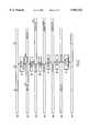
- FIG. 2is a flow diagram illustrating the operation of the method according to the invention.
- FIG. 1there is shown a block diagram of a data storage channel of the type in which the present invention may be implemented. More specifically, data from a data source 10 is input to a channel encoder 11 which outputs encoded data to channel 12.
- the encoderis implemented as a finite state automaton, an example of which is disclosed in U.S. Pat. No. 4,413,251 to Adler et al.
- the encoded datais run-length limited data, and the channel 12 may be a magnetic recording media to which the encoded data is written.
- the encoded datais read out of the channel 12 (e.g., the magnetic or optical media) and into the channel decoder 13 to recover the input data which is output to user 14.
- the user 14may be, for example, a computer system.
- the system thus far describedrepresents the current state of the prior art.
- the present inventionadds three new components to this basic system. They are the resolving block inserter 15, the synchronizer 16 and the resolving block deleter 17.
- resolving block inserter 15First, before the input data is sent to the channel encoder 11, resolving blocks are inserted into the input data by resolving block inserter 15. These resolving blocks are used to establish correct synchronization in the synchronizer 16. Finally, after the input data is recovered by the channel decoder 13, the resolving blocks are deleted by the resolving block deleter 17.
- Data emerging from the channel 12is subject to two types of errors, bit and slip errors.
- a 1 bit errorto be a 0 changed to a 1, a 1 changed to a 0, or a 1 transposed with an adjacent 0.
- n-slip errorto be an n time step synchronization difference between the encoded constrained string entering the channel and the string emerging from the channel.
- Bit errorsare dealt with by an error-correction encoder/decoder, the details of which are not shown here.
- This inventionis concerned with slip errors in the presence of bit errors. We shall discuss this invention for the Adler, Hassner, Missouris (1,7) code (see U.S. Pat. No. 4,413,251) and the Franaszek (2,7) code (see U.S. Pat. No. 3,689,899).
- the outputis three binary bits, and the state is A, B, C, D, or E.
- the following resolving blockproduces an encoded (1,7) constrained block which corrects up to 2-slip errors in the presence of no bit errors.
- the following resolving blockproduces an encoded (1,7) constrained block which corrects up to 5-slip errors in the presence of no bit errors. In addition it will correct up to 2-slip errors in the presence of up to one bit error.
- the following resolving blockproduces all encoded (1,7) constrained block which corrects up to 4-slip errors in the presence of no more than one bit error.
- the outputis two binary bits, and the state is A, B or C.
- the data stringis first padded by 00 and the encoder begins in state B.
- a resolving blockis chosen to correct the specific number of slip errors within the specified bit error tolerance.
- the resolving blockis inserted into the data string at regular intervals specified by the resynchronization frequency. This is done by the resolving block insert 15 of FIG. 1.
- the encloser 11converts the data string into a constrained one and converts the resolving block into a specific synchronizing block at a specific location.
- the constrained stringpasses through the channel 12.
- the synchronizer 16expects the synchronizing block to occur at a specific location. If a slip error has occurred, within the bit and slip error tolerance, then the synchronizer 16 detects and corrects the slip error.
- the decoder 13converts the constrained string back into a data string.
- the resolving block deleter 17removes the resolving blocks at their specified locations.
- the data string 20is shown as divided into increments of 500 bits.
- the resolving block inserterinserts the resolving block at 21 into the data string 20 after every 500 data bits.
- the resulting 512 bits, indicated at 22 in FIG. 2are converted into 768 constrained bits 24 by the encoder at 23.
- the resolving blockis converted into the synchronizing block XXX 010 100 000 001 010 010.
- the received data string 26is input to the synchronizer at 27.
- the synchronizerexpects this block at the end of every block of 768 constrained bits, as indicated at 26 and 28 in FIG. 2.
- the synchronizerresynchronizes the string which it is able to do because of the way the synchronizing block was chosen.
- the resolving block deleterremoves the final twelve bits of each block of length 512 of unconstrained bits at 31, restoring the data string to that of the source 20, as represented by 32.
Landscapes
- Detection And Correction Of Errors (AREA)
- Signal Processing For Digital Recording And Reproducing (AREA)
Abstract
Description
state→next state/output
______________________________________input = 00 01 10 11______________________________________A→ A/010 B/010 C/010 D/010B→ A/001 B/001 E/001 E/010C→ A/100 B/100 C/100 D/100D→ A/101 B/101 E/101 E/100E→ A/000 B/000 C/000 D/000______________________________________
______________________________________resolving block 01 11 --encoded block -- 010 000______________________________________
______________________________________resolving block 01 10 01 00 --encoded block -- 001 000 001 010______________________________________
______________________________________resolving block 00 11 11 01 00 00 --encoded block -- 010 100 000 001 010 010 (2,7) code______________________________________
state→next state/output
______________________________________input = 0.00 0.01 0.10 0.11 1.0- 1.1-______________________________________A→ B/00 A/00 B/10 B/00 A/00 B/10B→ C/01 C/01 B/10 B/00 C/01 C/10C→ A/00 A/00 B/00 B/00 A/00 B/00______________________________________
Claims (12)
Priority Applications (1)
| Application Number | Priority Date | Filing Date | Title |
|---|---|---|---|
| US08/987,208US5963152A (en) | 1997-12-09 | 1997-12-09 | Resolving block method for synchronization correction in run-length limited codes |
Applications Claiming Priority (1)
| Application Number | Priority Date | Filing Date | Title |
|---|---|---|---|
| US08/987,208US5963152A (en) | 1997-12-09 | 1997-12-09 | Resolving block method for synchronization correction in run-length limited codes |
Publications (1)
| Publication Number | Publication Date |
|---|---|
| US5963152Atrue US5963152A (en) | 1999-10-05 |
Family
ID=25533105
Family Applications (1)
| Application Number | Title | Priority Date | Filing Date |
|---|---|---|---|
| US08/987,208Expired - LifetimeUS5963152A (en) | 1997-12-09 | 1997-12-09 | Resolving block method for synchronization correction in run-length limited codes |
Country Status (1)
| Country | Link |
|---|---|
| US (1) | US5963152A (en) |
Cited By (2)
| Publication number | Priority date | Publication date | Assignee | Title |
|---|---|---|---|---|
| US20050258345A1 (en)* | 2004-05-21 | 2005-11-24 | Silicon Light Machines Corporation | Optical position sensing device including interlaced groups of photosensitive elements |
| US20110320568A1 (en)* | 2000-01-28 | 2011-12-29 | Slik David B | Content distribution system for generating content streams to suit different users and facilitating e-commerce transactions using broadcast content metadata |
Citations (5)
| Publication number | Priority date | Publication date | Assignee | Title |
|---|---|---|---|---|
| US4833470A (en)* | 1986-07-15 | 1989-05-23 | Matsushita Electric Industrial Co., Ltd. | Code conversion apparatus |
| US5220568A (en)* | 1988-05-31 | 1993-06-15 | Eastman Kodak Company | Shift correcting code for channel encoded data |
| US5623477A (en)* | 1993-03-15 | 1997-04-22 | Matsushita Electric Industrial Co., Ltd. | Optical recording disk capable of resynchronization in digital encoding and decoding |
| US5682153A (en)* | 1995-06-30 | 1997-10-28 | Fujitsu Limited | Adjust bit determining circuit |
| US5815514A (en)* | 1996-02-09 | 1998-09-29 | Overland Data, Inc. | Variable rate bit inserter for digital data storage |
- 1997
- 1997-12-09USUS08/987,208patent/US5963152A/ennot_activeExpired - Lifetime
Patent Citations (5)
| Publication number | Priority date | Publication date | Assignee | Title |
|---|---|---|---|---|
| US4833470A (en)* | 1986-07-15 | 1989-05-23 | Matsushita Electric Industrial Co., Ltd. | Code conversion apparatus |
| US5220568A (en)* | 1988-05-31 | 1993-06-15 | Eastman Kodak Company | Shift correcting code for channel encoded data |
| US5623477A (en)* | 1993-03-15 | 1997-04-22 | Matsushita Electric Industrial Co., Ltd. | Optical recording disk capable of resynchronization in digital encoding and decoding |
| US5682153A (en)* | 1995-06-30 | 1997-10-28 | Fujitsu Limited | Adjust bit determining circuit |
| US5815514A (en)* | 1996-02-09 | 1998-09-29 | Overland Data, Inc. | Variable rate bit inserter for digital data storage |
Cited By (2)
| Publication number | Priority date | Publication date | Assignee | Title |
|---|---|---|---|---|
| US20110320568A1 (en)* | 2000-01-28 | 2011-12-29 | Slik David B | Content distribution system for generating content streams to suit different users and facilitating e-commerce transactions using broadcast content metadata |
| US20050258345A1 (en)* | 2004-05-21 | 2005-11-24 | Silicon Light Machines Corporation | Optical position sensing device including interlaced groups of photosensitive elements |
Similar Documents
| Publication | Publication Date | Title |
|---|---|---|
| TW307077B (en) | Reformatting of variable rate data for fixed rate communication | |
| US5376969A (en) | Method and apparatus for conveying compressed video data over a noisy communication channel | |
| US4271520A (en) | Synchronizing technique for an error correcting digital transmission system | |
| KR960028573A (en) | Synchronization and Error Detection of Packetized Data Streams | |
| US5832001A (en) | Variable rate viterbi decorder | |
| US8230314B1 (en) | Universal parity decoder | |
| MY112024A (en) | Method and apparatus for encoding and decoding information in a digital communication system | |
| JP3764453B2 (en) | Encoding apparatus and method and decoding apparatus and method for error correction | |
| US5955977A (en) | System for avoiding start code emulation and long carry-over propagation | |
| JP3217298B2 (en) | nB2P code and decoding device | |
| Girod | Bidirectionally decodable streams of prefix code-words | |
| US5963152A (en) | Resolving block method for synchronization correction in run-length limited codes | |
| JP4424855B2 (en) | Method and apparatus for avoiding prohibited pattern of audio / video data | |
| US5146462A (en) | System and devices for transmitting signals consisting of data blocks | |
| JP2786342B2 (en) | Viterbi decoder | |
| JPH10178419A (en) | Error correction method and device | |
| JP3269035B2 (en) | Decryption device | |
| US6510248B1 (en) | Run-length decoder with error concealment capability | |
| US6707396B2 (en) | Device and method for parallel processing implementation of bit-stuffing/unstuffing and NRZI-encoding/decoding | |
| US6753797B2 (en) | Multiproperty 16/17 trellis code | |
| JPS63502948A (en) | Digital data transmission with error detection function including word framing error | |
| US6944234B2 (en) | Coding method and apparatus for reducing number of state transition paths in a communication system | |
| Perkins et al. | A scheme for the synchronization of variable length codes | |
| JP2762528B2 (en) | Transmission line encoding / decoding method | |
| KR100313884B1 (en) | Apparatus for data coding |
Legal Events
| Date | Code | Title | Description |
|---|---|---|---|
| AS | Assignment | Owner name:IBM CORPORATION, NEW YORK Free format text:ASSIGNMENT OF ASSIGNORS INTEREST;ASSIGNORS:ADLER, ROY L.;HASSNER, MARTIN A.;KITCHENS, BRUCE P.;REEL/FRAME:008899/0183;SIGNING DATES FROM 19971201 TO 19971209 | |
| FEPP | Fee payment procedure | Free format text:PAYOR NUMBER ASSIGNED (ORIGINAL EVENT CODE: ASPN); ENTITY STATUS OF PATENT OWNER: LARGE ENTITY | |
| STCF | Information on status: patent grant | Free format text:PATENTED CASE | |
| FPAY | Fee payment | Year of fee payment:4 | |
| FPAY | Fee payment | Year of fee payment:8 | |
| REMI | Maintenance fee reminder mailed | ||
| FPAY | Fee payment | Year of fee payment:12 | |
| SULP | Surcharge for late payment | Year of fee payment:11 | |
| AS | Assignment | Owner name:GOOGLE INC., CALIFORNIA Free format text:ASSIGNMENT OF ASSIGNORS INTEREST;ASSIGNOR:INTERNATIONAL BUSINESS MACHINES CORPORATION;REEL/FRAME:026664/0866 Effective date:20110503 | |
| AS | Assignment | Owner name:GOOGLE LLC, CALIFORNIA Free format text:CHANGE OF NAME;ASSIGNOR:GOOGLE INC.;REEL/FRAME:044127/0735 Effective date:20170929 |