US5963144A - Cloaking circuit for use in a radiofrequency identification and method of cloaking RFID tags to increase interrogation reliability - Google Patents
Cloaking circuit for use in a radiofrequency identification and method of cloaking RFID tags to increase interrogation reliabilityDownload PDFInfo
- Publication number
- US5963144A US5963144AUS08/865,799US86579997AUS5963144AUS 5963144 AUS5963144 AUS 5963144AUS 86579997 AUS86579997 AUS 86579997AUS 5963144 AUS5963144 AUS 5963144A
- Authority
- US
- United States
- Prior art keywords
- antenna
- rfid tag
- circuit
- coupled
- switch
- Prior art date
- Legal status (The legal status is an assumption and is not a legal conclusion. Google has not performed a legal analysis and makes no representation as to the accuracy of the status listed.)
- Expired - Lifetime
Links
Images

Classifications
- G—PHYSICS
- G06—COMPUTING OR CALCULATING; COUNTING
- G06K—GRAPHICAL DATA READING; PRESENTATION OF DATA; RECORD CARRIERS; HANDLING RECORD CARRIERS
- G06K19/00—Record carriers for use with machines and with at least a part designed to carry digital markings
- G06K19/06—Record carriers for use with machines and with at least a part designed to carry digital markings characterised by the kind of the digital marking, e.g. shape, nature, code
- G06K19/067—Record carriers with conductive marks, printed circuits or semiconductor circuit elements, e.g. credit or identity cards also with resonating or responding marks without active components
- G06K19/07—Record carriers with conductive marks, printed circuits or semiconductor circuit elements, e.g. credit or identity cards also with resonating or responding marks without active components with integrated circuit chips
- G06K19/0723—Record carriers with conductive marks, printed circuits or semiconductor circuit elements, e.g. credit or identity cards also with resonating or responding marks without active components with integrated circuit chips the record carrier comprising an arrangement for non-contact communication, e.g. wireless communication circuits on transponder cards, non-contact smart cards or RFIDs
- G—PHYSICS
- G06—COMPUTING OR CALCULATING; COUNTING
- G06K—GRAPHICAL DATA READING; PRESENTATION OF DATA; RECORD CARRIERS; HANDLING RECORD CARRIERS
- G06K7/00—Methods or arrangements for sensing record carriers, e.g. for reading patterns
- G06K7/0008—General problems related to the reading of electronic memory record carriers, independent of its reading method, e.g. power transfer
- G—PHYSICS
- G01—MEASURING; TESTING
- G01S—RADIO DIRECTION-FINDING; RADIO NAVIGATION; DETERMINING DISTANCE OR VELOCITY BY USE OF RADIO WAVES; LOCATING OR PRESENCE-DETECTING BY USE OF THE REFLECTION OR RERADIATION OF RADIO WAVES; ANALOGOUS ARRANGEMENTS USING OTHER WAVES
- G01S13/00—Systems using the reflection or reradiation of radio waves, e.g. radar systems; Analogous systems using reflection or reradiation of waves whose nature or wavelength is irrelevant or unspecified
- G01S13/74—Systems using reradiation of radio waves, e.g. secondary radar systems; Analogous systems
- G01S13/75—Systems using reradiation of radio waves, e.g. secondary radar systems; Analogous systems using transponders powered from received waves, e.g. using passive transponders, or using passive reflectors
- G01S13/751—Systems using reradiation of radio waves, e.g. secondary radar systems; Analogous systems using transponders powered from received waves, e.g. using passive transponders, or using passive reflectors wherein the responder or reflector radiates a coded signal
- G01S13/758—Systems using reradiation of radio waves, e.g. secondary radar systems; Analogous systems using transponders powered from received waves, e.g. using passive transponders, or using passive reflectors wherein the responder or reflector radiates a coded signal using a signal generator powered by the interrogation signal
Definitions
- the inventionrelates to radio frequency identification tags or labels and in particular to a cloaking circuit used to assist in the read operations of RFID transponders.
- Marsh et al, "Electronic Identification System," U.S. Pat. No. 5,537,105 (1987)describes an identification system utilizing an interrogator and plurality of transponder tags or labels.
- the systemutilizes an interrogator/reader 2 for identifying one or more transponders 4 within a monitored space as diagrammatically depicted in Marsh's FIG. 1.
- the interrogatortransmits a radio frequency signal, which when received by the transponder, is utilized by the transponder to provide DC power to the transponder.
- Both the interrogator and transponderutilize coded transmissions.
- the transponderstransmit a reply after a random delay time period allowing the multiple transponders within the same field of view of the interrogator to be individually read due to the reduced chance of collision between respective transponder output signals.
- each transponder unitturns itself off after the reader has successfully identified the transponder.
- the shut down circuitis indicated by a momentary cessation of the interrogation signal.
- a transponder transmissionis disabled by means of flip-flop 38 disposed between code generator 36 and modulator 40.
- the flip-flopis switched to disable the modulator input responsive to logic circuit 42.
- Logic circuit 42monitors the presence of the interrogation signal from the transponder receiving antenna 30.
- the transpondersare subsequently reset by removal of the interrogation signal for predetermined time.
- U.S. Pat. No. 5,471,196 (1995)shows in FIG. 4 a transponder including a transmitter 5 and receiver 4 which are coupled to an antenna 7. Antenna 7 is tuned by capacitor 1 through a switch 3. Switch 3, receiver 4 and transmitter 5 are controlled by logic circuit 6. Subsequent to the transmission period, T1, switch 3 is opened detuning antenna 7 and preventing transmission through antenna 7 until the next transmit time period. During time period T2 that switch 3 is open, the security system is able to receive reply signals from other transponders.
- Cato et al."Time Division Multiplexed Batch Mode Item Identification System," U.S. Pat. No. 5,539,394 (1996) describes a system for reading a plurality of identification tags and labels in which a interrogator/reader broadcasts an interrogation signal which initiates transmission from the tags.
- the tagsare designed to output within a predefined time slot.
- an acknowledge signalis transmitted to the tags.
- the tagscease communication in response to the acknowledge signal thereby allowing similarly coded tags to be read.
- the interfering tagretransmits signals in different time slots based on the timing signal transmitted from the interrogating system.
- Dingwall et al."System and Method for Remote Identification of Coded Articles and the Like," U.S. Pat. No. 5,502,445 (1996) describe a system in which badges 14 are interrogated by a beam 16 transmitted from directional antennas 18 of an interrogator/receiver unit 12. Dingwall was cited for showing that once a badge has been identified, an electronic circuit is put into an inactive or power-down state so that it will no longer respond to the interrogation/receiver unit as long as the badge remains within the range of beam 16 in order to facilitate identification of other badges 14.
- the primary prior art method for preventing RFID transponders from interfering with on-going reader operationshas been to use a logic circuit to disable the RFID transponder from replying to the interrogation signal, the purpose being to improve communication with multiple tags by reducing the likelihood of interference.
- the tagupon successfully transmitting the data, the tag receives a coded signal from the transmitter acknowledging its receipt.
- Logic circuits on the tagthen enter a state that prevents further responses by the tag until either a second coded signal reactivates a response mode or until the tag is removed from and then re-enters the powering RF field.
- the powering off and on cyclehas the effect of resetting the logic circuit in the RFID tag allowing it to respond anew.
- the antenna of an RFID tag or labelis disconnected from the balance of the RFID chip by means of a series switch activated in response to a logic command, CLOAK, generated by the RFID chip. Activation of the switch disconnects the antenna of the RFID tag from the remainder of the RFID chip and effects a high impedance resistance across the antenna terminals.
- An RC circuitis charged by activation of the CLOAK signal and thereafter discharges during a predetermined RC time period as determined by a high impedance series antifuse leakage transistor. The antenna is thus disconnected for a time sufficient to allow the remaining RFID tags in an RF interrogation field to be identified.
- the interrogated tagremains disconnected and noninterferring with the RF field used to interrogate the remaining tags.
- the inventionis defined as an improvement in an RFID tag passively powered through an antenna comprising a series switch coupled between the antenna and the RFID tag.
- a time-delay circuitis coupled to and controls the series switch to activate the series switch to disconnect the RFID tag from the antenna for a predetermined time delay.
- the timed-delay circuitis activated by a logic command, CLOAK, which is generated by the RFID tag.
- the antennais provided during the predetermined time period with a high impedance load, thereby reducing the effective absorption and scattering aperture of the antenna during the predetermined time period.
- the time-delay circuitcomprises an RC circuit and generates the pre-determined time period with a duration approximately 2-5 seconds long.
- the RC circuitincludes an integrated circuit capacitor and a high impedance of series antifuse coupled in parallel to the integrated circuit capacitor as a discharging resistor.
- the series switchdisconnects input data received from the antenna from the RFID tag and disconnects a tag chip voltage V DD from the antenna.
- the improvementfurther comprises a rectifier bridge coupled to the antenna, a control device and an RC circuit.
- the bridgeis coupled in series with the series switch to the RFID tag.
- the series switchincludes the control device which is coupled to the bridge.
- the control deviceis coupled to the RC circuit.
- the control deviceis responsive to a logic signal, CLOAK, generated by the RFID tag to cause the RC circuit to be charged and to open the series switch to disconnect the antenna from the RFID tag for a predetermined time period as determined by the RC circuit.
- the series switchis also controlled by the control device to disconnect input data to the RFID tag received from the antenna.
- the inventionis also defined as a method of cloaking an RFID tag in an RF field comprising the steps of powering the RFID tag in the RF field and generating a logic signal, CLOAK, on a predetermined condition as determined by the RFID tag.
- a time-delay circuitis activated upon generation of the logic signal, CLOAK, to generate a predetermined time delay.
- a switchis activated to effectively open circuit the antenna for the predetermined time delay so that the effective absorption and scattering aperture of the antenna are minimized, or at least substantially reduced during the predetermined time delay.
- the step of activating the time delaycomprises charging an RC circuit to generate a control signal for opening the switch during an RC time delay as determined by the RC circuit.
- the step of activating the switchcouples a high impedance load to the antenna to effectively open circuit the antenna during the predetermined time delay.
- the RFID tag coupled to the open circuited antennais defined as a cloaked RFID tag, and wherein the predetermined time delay equals or exceeds a duration sufficient to allow identification of remaining RFID tags in the RF field, so that the cloaked RFID tag is included among a plurality of RFID tags in the RF field.
- FIG. 1is a block diagram showing an illustrative RFID in which the cloaking circuit of the invention is used.
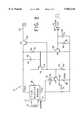
- FIG. 2is a simplified schematic diagram of the cloaking circuit of the invention.
- the antenna of the RFID tagremains disconnected or loaded by a high impedance during the power on/off cycles, in the absence of the powering RF field and until the RC delay times out.
- the time delaysare dependent on the exact process parameters utilized in fabricating the RFID tag and typically may be in the range of 2-5 seconds.
- the impedance coupled to the antenna terminals by the RFID chipis raised sufficiently high so that the antenna appears to be effectively open-circuited. This causes the antenna and the RFID tag to have both reduced absorption and reflection of the RF energy.
- the advantage of the performance of an RFID system of the inventionis that during the time that the antenna is effectively disconnected, the tag appears less visible in the RF field or is cloaked.
- the cloaked antennainterferes less with other tags, which are then going through the interrogation or identification process.
- a coded signalis transmitted to tell the identified tag to cloak itself. When in the cloaked state, this allows therefore more energy in the RF field to be available for reading the remaining tags in the interrogation zone.
- the overall capacity to read and identify multiple tags within the read range of a RFID systemis significantly improved as a result of applying this concept.
- FIG. 1is a simplified block diagram of an RFID tag, generally drawn by reference numeral 100.
- a tag core block 102is coupled to a memory 104, which stores user data for later recall.
- a data path section 106is coupled to tag core 102 and provides for a plurality of 17 bit data registers and logic circuitry associated with the registers.
- An analog section 108is also coupled to tag core 102 and includes antenna 16 as shown and described below in FIG. 2.
- Analog section 108includes cloaking circuit 10 of the invention and provides the input power drawn through antenna 16 from the RF field for powering tag 100. Cloaking circuit 10 of the invention shown in FIG.
- FIG. 2selectively places a high impedance across terminals of antenna 16 to effectively open circuit the antenna and to disconnect tag core 102 from both its data input and from its power supply. It must be understood that many other tag organizations can be employed other than that shown in FIG. 1 which is illustrated only for the purposes of context. The operation and details of each of the circuit blocks shown in FIG. 1, being largely immaterial to the invention, will therefore not be further discussed in detail. The cloaking circuit of FIG. 2 therefore is explicitly understood to be used in any type of RFID tag or label, whether it has the architecture of tag 100 in FIG. 1 or not.
- FIG. 2is a simplified schematic diagram of the cloaking circuit portion of an RFID tag designed according to the invention.
- the cloaking circuitgenerally denoted by reference numeral 10, is coupled at terminals 12 and 14 to an antenna 16.
- Antenna 16is shown in generalized form may include any type of antenna design now known or later discovered.
- Terminals 12 and 14are in turn coupled to a DC diode rectifier bridge 18.
- Rectifier bridgegenerates the tag chip power supply voltage, V DD from RF energy received by antenna 16.
- the power supply voltage in the cloaking circuit of FIG. 2is denoted as V DDC .
- the ground terminal of bridge 18is the chip ground voltage, V SS .
- Power thus received by antenna 16is converted into a modulated DCC used to power the RFID tag and to provide the coded information transmitted to and from the tag.
- the schematic of FIG. 2shows a part of analog section 108 that performs conversion of RF power to DC voltage to power RFID chip 100 and to convert the RF pulses into digital data signals.
- the circuit of FIG. 2also includes a cloaking feature of the invention as described below.
- P type field effect transistor (PFET) 20acts as a switch to connect or disconnect antenna 16 and diode rectifier bridge 18 from the rest of RFID chip 100.
- transistor 20When chip 100 is operating, transistor 20 is held in the on or conducting state by having its gate tied to V SS through resistor 44, allowing rectifier voltage V DDC to be coupled on line 22 to the rest of chip 100.
- transistor 20, along with PFET 24are turned off and chip 100 is disconnected from antenna 16 and rectifier bridge 18. Transistor 24 is turned off to isolate the data input portion of this block.
- terminal 14 of antenna 16is coupled through zener diode 26 to the source of transistor 24 whose drain is coupled to node 28, which provides the DATA-IN signal to chip 100, which is the digital data signal carried on the modulation on RF power field received by antenna 16.
- Node 28in turn is coupled through resistor 30 to ground, V SS .
- CLOAKdigital cloaking signal
- NFETN type field effect transistor
- Resistor 36 and capacitor 38assures that CLOAK must be active for an adequate time to turn on transistor 34 and that transistor 34 is held on for an appropriate time.
- transistor 34When transistor 34 is on the voltage V DDC is applied across integrated circuit capacitor 40, which is charged to approximately V DDC .
- Transistor 34is also coupled to the gate of PFET 42, which is then pulled low and transistor 42 is turned on.
- Transistor 42is coupled in series with a high impedance resistor 44 to V SS . When transistor 42 is turned on, the gates of transistors 24 and 20 to which the drain of transistor 42 is connected go high and are turned off.
- transistors 24 and 20With the gates of transistors 24 and 20 pulled high to V DDC , transistors 24 and 20 are turned off, thereby disconnecting DATA IN node 28 and V DDC from line 22, the voltage supply line V DD , of RFID chip 100. This completes the cloaking operation which effectively disconnects antenna 16 from RFID circuit 100.
- Transistor 42is maintained in the on condition as long as there is sufficient voltage applied to its gate or current is stored on capacitor 40.
- the voltage on capacitor 40will decay at a rate set by the time constant of capacitor 40 which discharges through discharging resistor 46 which is coupled in parallel to capacitor 40.
- Capacitor 40 and resistor 46therefore define an RC time-constant for an interval during which the RFID circuit will be cloaked.
- Resistor 46 in the preferred embodimentis a series connected structure of antifuses having a high impedance to allow a 2-5 second cloaking period to be effective without requiring a discrete element for capacitor 40 or a large capacity. Since capacitor 40 will typically have a capacity in the tens of picofarads, resistor 46 typically will have an impedance in the range of 10 to 100 gigaohms.
- RFID chip 100While cloaked, RFID chip 100 presents a high impedance to antenna 16.
- the impedance load across terminals 12 and 14 of antenna 16 when control transistor 42 is turned onwill be at equal to at least the impedance of resistor 44, which in the illustrated embodiment is chosen as a 6 gigaohm integrated circuit resistor.
- Antenna 16will thus be heavily loaded during cloaking and will be effectively open circuited.
- effective scattering and absorption aperture of antenna 16decrease.
- the effective absorptive and scattering aperture of antenna 16will approach zero for a nearly true open-circuited condition.
- With a reduced antenna aperturesless energy is absorbed or reflected from the cloaked RFID tags or labels, thereby allowing more RF energy in the interrogation field to reach other RFID tags in the field, thus increasing the reliability of reading them.
Landscapes
- Engineering & Computer Science (AREA)
- Physics & Mathematics (AREA)
- General Physics & Mathematics (AREA)
- Theoretical Computer Science (AREA)
- Artificial Intelligence (AREA)
- Computer Vision & Pattern Recognition (AREA)
- Computer Networks & Wireless Communication (AREA)
- Computer Hardware Design (AREA)
- Microelectronics & Electronic Packaging (AREA)
- Near-Field Transmission Systems (AREA)
- Credit Cards Or The Like (AREA)
- Radar Systems Or Details Thereof (AREA)
Abstract
Description
Claims (18)
Priority Applications (6)
| Application Number | Priority Date | Filing Date | Title |
|---|---|---|---|
| US08/865,799US5963144A (en) | 1997-05-30 | 1997-05-30 | Cloaking circuit for use in a radiofrequency identification and method of cloaking RFID tags to increase interrogation reliability |
| CA002286602ACA2286602C (en) | 1997-05-30 | 1998-05-29 | Cloaking circuit for use in a radio frequency identification and method of cloaking rfid tags to increase interrogation reliability |
| PCT/US1998/010994WO1998054912A1 (en) | 1997-05-30 | 1998-05-29 | Cloaking circuit for use in a radio frequency identification and method of cloaking rfid tags to increase interrogation reliability |
| DE69839938TDE69839938D1 (en) | 1997-05-30 | 1998-05-29 | CLOAK SWITCHING FOR RADIO FREQUENCY IDENTIFICATION SET QUERY REPLACEMENT INCREASE |
| EP98923849AEP0983692B1 (en) | 1997-05-30 | 1998-05-29 | Cloaking circuit for use in radio frequency identification tags and method of cloaking rfid tags to increase interrogation reliability |
| JP50096199AJP3995724B2 (en) | 1997-05-30 | 1998-05-29 | Cloaking circuit for use in radio frequency identification and method for concealing RFID tag to improve query reliability |
Applications Claiming Priority (1)
| Application Number | Priority Date | Filing Date | Title |
|---|---|---|---|
| US08/865,799US5963144A (en) | 1997-05-30 | 1997-05-30 | Cloaking circuit for use in a radiofrequency identification and method of cloaking RFID tags to increase interrogation reliability |
Publications (1)
| Publication Number | Publication Date |
|---|---|
| US5963144Atrue US5963144A (en) | 1999-10-05 |
Family
ID=25346257
Family Applications (1)
| Application Number | Title | Priority Date | Filing Date |
|---|---|---|---|
| US08/865,799Expired - LifetimeUS5963144A (en) | 1997-05-30 | 1997-05-30 | Cloaking circuit for use in a radiofrequency identification and method of cloaking RFID tags to increase interrogation reliability |
Country Status (6)
| Country | Link |
|---|---|
| US (1) | US5963144A (en) |
| EP (1) | EP0983692B1 (en) |
| JP (1) | JP3995724B2 (en) |
| CA (1) | CA2286602C (en) |
| DE (1) | DE69839938D1 (en) |
| WO (1) | WO1998054912A1 (en) |
Cited By (101)
| Publication number | Priority date | Publication date | Assignee | Title |
|---|---|---|---|---|
| US6229443B1 (en)* | 2000-06-23 | 2001-05-08 | Single Chip Systems | Apparatus and method for detuning of RFID tag to regulate voltage |
| US20020017992A1 (en)* | 2000-06-05 | 2002-02-14 | Hitoshi Hidaka | Article identifying system |
| US6396438B1 (en) | 1999-09-24 | 2002-05-28 | Slc Technologies | System and method for locating radio frequency identification tags using three-phase antenna |
| US20020097143A1 (en)* | 2001-01-23 | 2002-07-25 | Dave Dalglish | Selective cloaking circuit for use in a radiofrequency identification and method of cloaking RFID tags |
| US6452504B1 (en) | 1999-09-24 | 2002-09-17 | Ge Interlogix, Inc. | System and method for communication with radio frequency identification tags using tow message DFM protocol |
| US6611556B1 (en) | 1999-05-21 | 2003-08-26 | Steve J. Koerner | Identification system for monitoring the presence/absence of members of a defined set |
| US20030164752A1 (en)* | 2000-04-28 | 2003-09-04 | Yosef Haimovitch | Apparatus and methods for cellular communication |
| US6661335B1 (en) | 1999-09-24 | 2003-12-09 | Ge Interlogix, Inc. | System and method for locating radio frequency identification tags |
| US6661339B2 (en) | 2000-01-24 | 2003-12-09 | Nextreme, L.L.C. | High performance fuel tank |
| US6693511B1 (en) | 1999-09-24 | 2004-02-17 | Ge Interlogix, Inc. | System and method for communicating with dormant radio frequency identification tags |
| US6721556B2 (en)* | 2000-02-18 | 2004-04-13 | Kabushiki Kaisha Toshiba | Radio communication apparatus and radio communication method |
| US20040075607A1 (en)* | 2000-04-26 | 2004-04-22 | Cathey David A. | Automated antenna trim for transmitting and receiving semiconductor devices |
| US20040129769A1 (en)* | 2002-10-09 | 2004-07-08 | Aram Kovach | Method for identifying and tracking test specimens |
| US20040143505A1 (en)* | 2002-10-16 | 2004-07-22 | Aram Kovach | Method for tracking and disposition of articles |
| US20040140884A1 (en)* | 1999-10-27 | 2004-07-22 | Microchip Technology Inc. | Anticollision protocol with fast read request and additional schemes for reading multiple transponders in an RFID system |
| US6779246B2 (en) | 2001-04-23 | 2004-08-24 | Appleton Papers Inc. | Method and system for forming RF reflective pathways |
| US20040181871A1 (en)* | 2003-02-27 | 2004-09-23 | Barton Medical Corporation | Furniture headboards and footboards |
| US20040201539A1 (en)* | 2003-04-09 | 2004-10-14 | Yewen Robert G. | Radio frequency identification system and antenna system |
| US20050057341A1 (en)* | 2003-09-17 | 2005-03-17 | Roesner Bruce B. | Deep sleep in an RFID tag |
| US20050088320A1 (en)* | 2003-10-08 | 2005-04-28 | Aram Kovach | System for registering and tracking vehicles |
| US6892441B2 (en) | 2001-04-23 | 2005-05-17 | Appleton Papers Inc. | Method for forming electrically conductive pathways |
| US20050179520A1 (en)* | 2004-02-13 | 2005-08-18 | Atmel Germany Gmbh | Method and circuit arrangement for holding a control state during inadequate power supply in an RF transponder or remote sensor |
| US6942155B1 (en)* | 2001-05-31 | 2005-09-13 | Alien Technology Corporation | Integrated circuits with persistent data storage |
| US6943678B2 (en) | 2000-01-24 | 2005-09-13 | Nextreme, L.L.C. | Thermoformed apparatus having a communications device |
| US6946950B1 (en)* | 1999-07-12 | 2005-09-20 | Matsushita Electric Industrial Co., Ltd. | Mobile body discrimination apparatus for rapidly acquiring respective data sets transmitted through modulation of reflected radio waves by transponders which are within a communication region of an interrogator apparatus |
| WO2005093455A1 (en)* | 2004-03-29 | 2005-10-06 | Magellan Technology Pty Ltd. | An article supply chain and/or authentication, monitoring, tracking and identification system, method and device |
| US6953919B2 (en) | 2003-01-30 | 2005-10-11 | Thermal Solutions, Inc. | RFID-controlled smart range and method of cooking and heating |
| WO2005121832A1 (en)* | 2004-06-09 | 2005-12-22 | Magellan Technology Pty Ltd | Method, system and apparatus for document management |
| US7002474B2 (en)* | 2002-07-17 | 2006-02-21 | Ncr Corporation | Radio frequency identification (RFID) tag and a method of operating an RFID tag |
| US20060046775A1 (en)* | 2004-08-31 | 2006-03-02 | Geiger Edward W | Intelligent antenna and method for configuring the same |
| US20060176239A1 (en)* | 2005-02-04 | 2006-08-10 | Philip Morris Usa Inc. | Display management system |
| US20060187040A1 (en)* | 2005-02-04 | 2006-08-24 | Philip Morris Usa Inc. | Controllable RFID card |
| US20060226955A1 (en)* | 2002-08-22 | 2006-10-12 | Murdoch Graham A M | Identification device and identification system |
| US20060250251A1 (en)* | 2005-05-06 | 2006-11-09 | Intelleflex Corporation | Semi-transparent RFID tags |
| US20060250220A1 (en)* | 2005-05-06 | 2006-11-09 | Intelleflex Corporation | Accurate persistent nodes |
| US20060264774A1 (en)* | 2005-08-25 | 2006-11-23 | Outland Research, Llc | Neurologically Controlled Access to an Electronic Information Resource |
| EP1732026A1 (en) | 2005-06-04 | 2006-12-13 | ATMEL Germany GmbH | Circuit, specially for use in RF transponders or remote sensors, and method for controlling a plurality of such transponders or sensors. |
| US20070018793A1 (en)* | 2005-07-20 | 2007-01-25 | Intelleflex Corporation | Ramped interrogation power levels |
| US20070046435A1 (en)* | 2005-08-29 | 2007-03-01 | Fratti Roger A | Biologically modeled RF ID tags |
| US20070060311A1 (en)* | 2005-09-12 | 2007-03-15 | Igt | Enhanced gaming chips and table game security |
| US20070069909A1 (en)* | 2005-09-29 | 2007-03-29 | Lear Corporation | System and method for verifying assembly of manufactured parts using rfid tags |
| US20070075140A1 (en)* | 2005-10-04 | 2007-04-05 | Gregory Guez | Means to deactivate a contactless device |
| US20070115098A1 (en)* | 2005-11-18 | 2007-05-24 | Wj Communications, Inc. | Rfid system including tags having low rf scattering mode |
| US20070114846A1 (en)* | 2005-11-23 | 2007-05-24 | Slobadan Pavlovic | Power supply circuit for removable automotive interior systems with integrated position sensor system |
| US20070132556A1 (en)* | 2000-02-28 | 2007-06-14 | Littlechild Stuart Colin | Radio frequency identification transponder |
| US20070159336A1 (en)* | 2006-01-06 | 2007-07-12 | Sdgi Holdings, Inc | Coiled RFID tag |
| WO2007044144A3 (en)* | 2005-10-04 | 2007-07-26 | Atmel Corp | A means to deactivate a contactless device |
| US7258276B2 (en) | 2000-10-20 | 2007-08-21 | Promega Corporation | Radio frequency identification method and system of distributing products |
| CN100337242C (en)* | 2002-08-21 | 2007-09-12 | 汤姆森特许公司 | Appliance with an IC card reader and overload protection circuit |
| US20070229278A1 (en)* | 2004-06-10 | 2007-10-04 | Minehisa Nagata | Radio Tag and Radio Tag Communication Distance Modification Method |
| US20070279195A1 (en)* | 2001-02-28 | 2007-12-06 | Littlechild Stuart Colin | Radio frequency identification transponder |
| US20080030307A1 (en)* | 2006-08-03 | 2008-02-07 | Holtek Semiconductor Inc. | Rfid transponder |
| US7377445B1 (en) | 2001-05-31 | 2008-05-27 | Alien Technology Corporation | Integrated circuits with persistent data storage |
| CN100394432C (en)* | 2004-04-01 | 2008-06-11 | 艾迪讯科技股份有限公司 | Radio frequency electronic label capable of having non-action state |
| US20080150721A1 (en)* | 2005-07-27 | 2008-06-26 | Zih Corp. | Visual identification tag deactivation |
| US20080180219A1 (en)* | 2005-07-02 | 2008-07-31 | Martin Fischer | Circuit arrangement for use in rf transponders and method for controlling a number of such transponders |
| US20080238680A1 (en)* | 2007-03-30 | 2008-10-02 | Posamentier Joshua D | Temporary non-responsive state for RFID tags |
| US20080272893A1 (en)* | 2005-03-30 | 2008-11-06 | Nxp B.V. | Integrated Circuit Providing an External Switching Functionality |
| US20090009405A1 (en)* | 2006-06-21 | 2009-01-08 | Broadcom Corporation | Integrated circuit with power supply line antenna structure and methods for use therewith |
| US20090140834A1 (en)* | 2007-12-03 | 2009-06-04 | Industrial Technology Research Institute | Apparatus having passive wireless switch and operating method thereof |
| US7573005B2 (en) | 2004-04-22 | 2009-08-11 | Thermal Solutions, Inc. | Boil detection method and computer program |
| US20090284218A1 (en)* | 2008-05-13 | 2009-11-19 | Qualcomm Incorporated | Method and apparatus for an enlarged wireless charging area |
| US7661591B2 (en) | 2000-10-20 | 2010-02-16 | Promega Corporation | RF point of sale and delivery method and system using communication with remote computer and having features to read a large number of RF tags |
| US20100087222A1 (en)* | 2008-10-03 | 2010-04-08 | Yukiko Yamashita | Modulation Circuit and Semiconductor Device Including the Same |
| US7710275B2 (en) | 2007-03-16 | 2010-05-04 | Promega Corporation | RFID reader enclosure and man-o-war RFID reader system |
| WO2010059376A1 (en)* | 2008-11-19 | 2010-05-27 | Greatbatch Ltd. | Rfid detection and identification system including an rfid reader having a limited transmit time and a time-out period to protect a medical device against rfid-associated electromagnetic interference |
| US20100171596A1 (en)* | 2008-12-31 | 2010-07-08 | Burke Peter J | In vivo rfid chip |
| US7884724B2 (en) | 1996-07-30 | 2011-02-08 | Round Rock Research, Llc | Radio frequency data communications device with selectively removable antenna portion and method |
| US7948371B2 (en) | 2000-01-24 | 2011-05-24 | Nextreme Llc | Material handling apparatus with a cellular communications device |
| US20110227703A1 (en)* | 2010-03-22 | 2011-09-22 | Kotab Dominic M | Systems and methods of reading gaming chips and other stacked items |
| US20110267173A1 (en)* | 2008-12-15 | 2011-11-03 | Cardlab Aps | Rfid tag |
| US8077040B2 (en) | 2000-01-24 | 2011-12-13 | Nextreme, Llc | RF-enabled pallet |
| CN101290650B (en)* | 2004-04-01 | 2012-10-10 | 艾迪讯科技股份有限公司 | Radio Frequency Electronic Tag with Inactive State, Its Reading System and Control Method |
| EP2575112A1 (en) | 2011-09-30 | 2013-04-03 | Joseph Joseph | Inventory and anti-theft alarm system |
| US8848905B1 (en)* | 2010-07-28 | 2014-09-30 | Sandia Corporation | Deterrence of device counterfeiting, cloning, and subversion by substitution using hardware fingerprinting |
| US8854224B2 (en) | 2009-02-10 | 2014-10-07 | Qualcomm Incorporated | Conveying device information relating to wireless charging |
| US8878393B2 (en) | 2008-05-13 | 2014-11-04 | Qualcomm Incorporated | Wireless power transfer for vehicles |
| US9312924B2 (en) | 2009-02-10 | 2016-04-12 | Qualcomm Incorporated | Systems and methods relating to multi-dimensional wireless charging |
| EP3035230A1 (en) | 2014-12-19 | 2016-06-22 | Cardlab ApS | A method and an assembly for generating a magnetic field |
| US9501664B1 (en) | 2014-12-15 | 2016-11-22 | Sandia Corporation | Method, apparatus and system to compensate for drift by physically unclonable function circuitry |
| US9583953B2 (en) | 2009-02-10 | 2017-02-28 | Qualcomm Incorporated | Wireless power transfer for portable enclosures |
| US9928696B2 (en)* | 2015-12-30 | 2018-03-27 | Immersion Corporation | Externally-activated haptic devices and systems |
| EP2417806B1 (en)* | 2009-04-07 | 2018-05-23 | QUALCOMM Incorporated | Wireless power transmission scheduling |
| US10031582B2 (en) | 2014-06-05 | 2018-07-24 | Immersion Corporation | Systems and methods for induced electrostatic haptic effects |
| US10095968B2 (en) | 2014-12-19 | 2018-10-09 | Cardlabs Aps | Method and an assembly for generating a magnetic field and a method of manufacturing an assembly |
| US20190139338A1 (en)* | 2017-11-06 | 2019-05-09 | Nxp B.V. | Electronic identification device |
| US20190163942A1 (en)* | 2017-11-29 | 2019-05-30 | Symbol Technologies, Llc | Operations of mobile rfid readers in a venue having fixed rfid readers |
| USRE47599E1 (en) | 2000-10-20 | 2019-09-10 | Promega Corporation | RF point of sale and delivery method and system using communication with remote computer and having features to read a large number of RF tags |
| US10558901B2 (en) | 2015-04-17 | 2020-02-11 | Cardlab Aps | Device for outputting a magnetic field and a method of outputting a magnetic field |
| US10650199B2 (en) | 2005-02-07 | 2020-05-12 | Steven Michael Colby | Passport including metallic fibers |
| US10956689B2 (en) | 2005-02-07 | 2021-03-23 | Mynette Technologies, Inc. | Passport including RFID shielding |
| US11270182B2 (en) | 2005-02-07 | 2022-03-08 | Mynette Technologies, Inc. | RFID financial device including mechanical switch |
| US20220138444A1 (en)* | 2020-11-02 | 2022-05-05 | Generalplus Technology Inc. | Radio frequency identification communication method for collision reduction with low power consumption and radio frequency identification communication system using the same |
| US11347949B2 (en) | 2005-05-06 | 2022-05-31 | Mynette Technologies, Inc. | Cellular device including inductive antenna |
| US11755874B2 (en) | 2021-03-03 | 2023-09-12 | Sensormatic Electronics, LLC | Methods and systems for heat applied sensor tag |
| US11769026B2 (en) | 2019-11-27 | 2023-09-26 | Sensormatic Electronics, LLC | Flexible water-resistant sensor tag |
| US11861440B2 (en) | 2019-09-18 | 2024-01-02 | Sensormatic Electronics, LLC | Systems and methods for providing tags adapted to be incorporated with or in items |
| US11869324B2 (en) | 2021-12-23 | 2024-01-09 | Sensormatic Electronics, LLC | Securing a security tag into an article |
| US11928538B2 (en) | 2019-09-18 | 2024-03-12 | Sensormatic Electronics, LLC | Systems and methods for laser tuning and attaching RFID tags to products |
| US12175849B2 (en) | 2018-05-22 | 2024-12-24 | Tyco Fire & Security Gmbh | Elongate flexible tag |
| US12223814B2 (en) | 2019-09-16 | 2025-02-11 | Sensormatic Electronics, LLC | Security tag for textiles using conductive thread |
Families Citing this family (4)
| Publication number | Priority date | Publication date | Assignee | Title |
|---|---|---|---|---|
| KR101107823B1 (en)* | 2004-11-23 | 2012-02-08 | 센소매틱 일렉트로닉스, 엘엘씨 | An integrated eas/rfid device and disabling devices therefor |
| WO2007131839A1 (en) | 2006-05-15 | 2007-11-22 | International Business Machines Corporation | METHOD AND SYSTEMS FOR LOCALIZING OBJECTS USING PASSIVE RFID TAGs |
| JP2019101735A (en)* | 2017-12-01 | 2019-06-24 | 東芝テック株式会社 | RFID tag |
| JP7518356B2 (en)* | 2020-06-16 | 2024-07-18 | 株式会社デンソーウェーブ | Interference suppression device and interference suppression system |
Citations (8)
| Publication number | Priority date | Publication date | Assignee | Title |
|---|---|---|---|---|
| US3694754A (en)* | 1970-12-28 | 1972-09-26 | Tracor | Suppression of electrostatic noise in antenna systems |
| US4414690A (en)* | 1980-06-20 | 1983-11-08 | U.S. Philips Corporation | Active aerial |
| US5074947A (en)* | 1989-12-18 | 1991-12-24 | Epoxy Technology, Inc. | Flip chip technology using electrically conductive polymers and dielectrics |
| US5418358A (en)* | 1992-08-20 | 1995-05-23 | Temic Telefunken Microelectronic Gmbh | Chip card with field strength detector having a switch and load to limit damping to the measurement cycle |
| US5471196A (en)* | 1990-02-19 | 1995-11-28 | Pilested; Karsten G. | Security system for surveilling the passage of commodities through defined zones |
| US5611140A (en)* | 1989-12-18 | 1997-03-18 | Epoxy Technology, Inc. | Method of forming electrically conductive polymer interconnects on electrical substrates |
| US5701121A (en)* | 1988-04-11 | 1997-12-23 | Uniscan Ltd. | Transducer and interrogator device |
| US5701595A (en)* | 1995-05-04 | 1997-12-23 | Nippondenso Co., Ltd. | Half duplex RF transceiver having low transmit path signal loss |
Family Cites Families (2)
| Publication number | Priority date | Publication date | Assignee | Title |
|---|---|---|---|---|
| DE69223381T2 (en)* | 1991-05-22 | 1998-06-10 | Kyodo Printing Co Ltd | CONTACTLESS IC CARD |
| US6079619A (en)* | 1997-08-05 | 2000-06-27 | Denso Corporation | Identification tag for wireless communication with remote controller |
- 1997
- 1997-05-30USUS08/865,799patent/US5963144A/ennot_activeExpired - Lifetime
- 1998
- 1998-05-29CACA002286602Apatent/CA2286602C/ennot_activeExpired - Lifetime
- 1998-05-29EPEP98923849Apatent/EP0983692B1/ennot_activeExpired - Lifetime
- 1998-05-29JPJP50096199Apatent/JP3995724B2/ennot_activeExpired - Lifetime
- 1998-05-29DEDE69839938Tpatent/DE69839938D1/ennot_activeExpired - Lifetime
- 1998-05-29WOPCT/US1998/010994patent/WO1998054912A1/enactiveApplication Filing
Patent Citations (10)
| Publication number | Priority date | Publication date | Assignee | Title |
|---|---|---|---|---|
| US3694754A (en)* | 1970-12-28 | 1972-09-26 | Tracor | Suppression of electrostatic noise in antenna systems |
| US4414690A (en)* | 1980-06-20 | 1983-11-08 | U.S. Philips Corporation | Active aerial |
| US5701121A (en)* | 1988-04-11 | 1997-12-23 | Uniscan Ltd. | Transducer and interrogator device |
| US5074947A (en)* | 1989-12-18 | 1991-12-24 | Epoxy Technology, Inc. | Flip chip technology using electrically conductive polymers and dielectrics |
| US5196371A (en)* | 1989-12-18 | 1993-03-23 | Epoxy Technology, Inc. | Flip chip bonding method using electrically conductive polymer bumps |
| US5237130A (en)* | 1989-12-18 | 1993-08-17 | Epoxy Technology, Inc. | Flip chip technology using electrically conductive polymers and dielectrics |
| US5611140A (en)* | 1989-12-18 | 1997-03-18 | Epoxy Technology, Inc. | Method of forming electrically conductive polymer interconnects on electrical substrates |
| US5471196A (en)* | 1990-02-19 | 1995-11-28 | Pilested; Karsten G. | Security system for surveilling the passage of commodities through defined zones |
| US5418358A (en)* | 1992-08-20 | 1995-05-23 | Temic Telefunken Microelectronic Gmbh | Chip card with field strength detector having a switch and load to limit damping to the measurement cycle |
| US5701595A (en)* | 1995-05-04 | 1997-12-23 | Nippondenso Co., Ltd. | Half duplex RF transceiver having low transmit path signal loss |
Cited By (220)
| Publication number | Priority date | Publication date | Assignee | Title |
|---|---|---|---|---|
| US7884724B2 (en) | 1996-07-30 | 2011-02-08 | Round Rock Research, Llc | Radio frequency data communications device with selectively removable antenna portion and method |
| US8624711B2 (en) | 1996-07-30 | 2014-01-07 | Round Rock Research, Llc | Radio frequency identification device operating methods, radio frequency identification device configuration methods, and radio frequency identification devices |
| US6611556B1 (en) | 1999-05-21 | 2003-08-26 | Steve J. Koerner | Identification system for monitoring the presence/absence of members of a defined set |
| US6946950B1 (en)* | 1999-07-12 | 2005-09-20 | Matsushita Electric Industrial Co., Ltd. | Mobile body discrimination apparatus for rapidly acquiring respective data sets transmitted through modulation of reflected radio waves by transponders which are within a communication region of an interrogator apparatus |
| US6693511B1 (en) | 1999-09-24 | 2004-02-17 | Ge Interlogix, Inc. | System and method for communicating with dormant radio frequency identification tags |
| US6452504B1 (en) | 1999-09-24 | 2002-09-17 | Ge Interlogix, Inc. | System and method for communication with radio frequency identification tags using tow message DFM protocol |
| US6396438B1 (en) | 1999-09-24 | 2002-05-28 | Slc Technologies | System and method for locating radio frequency identification tags using three-phase antenna |
| US6661335B1 (en) | 1999-09-24 | 2003-12-09 | Ge Interlogix, Inc. | System and method for locating radio frequency identification tags |
| US7079009B2 (en)* | 1999-10-27 | 2006-07-18 | Checkpoint Systems, Inc. | Anticollision protocol with fast read request and additional schemes for reading multiple transponders in an RFID system |
| US20040140884A1 (en)* | 1999-10-27 | 2004-07-22 | Microchip Technology Inc. | Anticollision protocol with fast read request and additional schemes for reading multiple transponders in an RFID system |
| US7752980B2 (en) | 2000-01-24 | 2010-07-13 | Nextreme Llc | Material handling apparatus having a reader/writer |
| US6661339B2 (en) | 2000-01-24 | 2003-12-09 | Nextreme, L.L.C. | High performance fuel tank |
| US8077040B2 (en) | 2000-01-24 | 2011-12-13 | Nextreme, Llc | RF-enabled pallet |
| US8585850B2 (en) | 2000-01-24 | 2013-11-19 | Nextreme, Llc | Thermoformed platform having a communications device |
| US9230227B2 (en) | 2000-01-24 | 2016-01-05 | Nextreme, Llc | Pallet |
| US6943678B2 (en) | 2000-01-24 | 2005-09-13 | Nextreme, L.L.C. | Thermoformed apparatus having a communications device |
| US7804400B2 (en) | 2000-01-24 | 2010-09-28 | Nextreme, Llc | Thermoformed platform having a communications device |
| US7948371B2 (en) | 2000-01-24 | 2011-05-24 | Nextreme Llc | Material handling apparatus with a cellular communications device |
| US6721556B2 (en)* | 2000-02-18 | 2004-04-13 | Kabushiki Kaisha Toshiba | Radio communication apparatus and radio communication method |
| US8159332B2 (en) | 2000-02-28 | 2012-04-17 | Magellan Technology Pty Limited | Radio frequency identification transponder |
| US20070139160A1 (en)* | 2000-02-28 | 2007-06-21 | Littlechild Stuart Colin | Radio frequency identification transponder |
| US8319609B2 (en) | 2000-02-28 | 2012-11-27 | Magellan Technology Pty Limited | Radio frequency identification transponder |
| US8325016B2 (en)* | 2000-02-28 | 2012-12-04 | Magellan Technology Pty Limited | Radio frequency identification transponder |
| US20080197976A1 (en)* | 2000-02-28 | 2008-08-21 | Littlechild Stuart Colin | Radio frequency identification transponder |
| US20070132556A1 (en)* | 2000-02-28 | 2007-06-14 | Littlechild Stuart Colin | Radio frequency identification transponder |
| US7417549B2 (en) | 2000-04-26 | 2008-08-26 | Keystone Technology Solutions, Llc | Automated antenna trim for transmitting and receiving semiconductor devices |
| US20040075607A1 (en)* | 2000-04-26 | 2004-04-22 | Cathey David A. | Automated antenna trim for transmitting and receiving semiconductor devices |
| US8134467B2 (en) | 2000-04-26 | 2012-03-13 | Round Rock Research, Llc | Automated antenna trim for transmitting and receiving semiconductor devices |
| US7812728B2 (en) | 2000-04-26 | 2010-10-12 | Round Rock Research, Llc | Methods and apparatuses for radio frequency identification (RFID) tags configured to allow antenna trim |
| US20070290861A1 (en)* | 2000-04-26 | 2007-12-20 | Micron Technology, Inc. | Automated antenna trim for transmitting and receiving semiconductor devices |
| US20050062607A1 (en)* | 2000-04-26 | 2005-03-24 | Cathey David A. | Automated antenna trim for transmitting and receiving semiconductor devices |
| US6806812B1 (en)* | 2000-04-26 | 2004-10-19 | Micron Technology, Inc. | Automated antenna trim for transmitting and receiving semiconductor devices |
| US7253737B2 (en) | 2000-04-26 | 2007-08-07 | Micron Technology, Inc. | Automated antenna trim for transmitting and receiving semiconductor devices |
| US20030164752A1 (en)* | 2000-04-28 | 2003-09-04 | Yosef Haimovitch | Apparatus and methods for cellular communication |
| US6960999B2 (en) | 2000-04-28 | 2005-11-01 | Hi-C-Tek Ltd. | Apparatus and methods for cellular communication |
| US20020017992A1 (en)* | 2000-06-05 | 2002-02-14 | Hitoshi Hidaka | Article identifying system |
| US6879264B2 (en)* | 2000-06-05 | 2005-04-12 | Kyuhoku Electronics, Inc. | Article identifying system |
| US6229443B1 (en)* | 2000-06-23 | 2001-05-08 | Single Chip Systems | Apparatus and method for detuning of RFID tag to regulate voltage |
| WO2002001890A1 (en)* | 2000-06-23 | 2002-01-03 | Single Chip Systems Corporation | An apparatus and method for detuning of rfid tag to regulate voltage |
| USRE46326E1 (en) | 2000-10-20 | 2017-02-28 | Promega Corporation | RF point of sale and delivery method and system using communication with remote computer and having features to read a large number of RF tags |
| US7591421B2 (en) | 2000-10-20 | 2009-09-22 | Promega Corporation | Radio frequency identification method and system of distributing products |
| US7293705B2 (en) | 2000-10-20 | 2007-11-13 | Promega Corporation | Radio frequency identification method and system of distributing products |
| US8025228B2 (en) | 2000-10-20 | 2011-09-27 | Promega Corporation | RF point of sale and delivery method and system using communication with remote computer and having features to read a large number of RF tags |
| US7967199B2 (en) | 2000-10-20 | 2011-06-28 | Promega Corporation | Radio frequency identification method and system of distributing products |
| US7258276B2 (en) | 2000-10-20 | 2007-08-21 | Promega Corporation | Radio frequency identification method and system of distributing products |
| US7942321B2 (en) | 2000-10-20 | 2011-05-17 | Promega Corporation | Radio frequency identification method and system of disturbing products |
| US7791479B2 (en) | 2000-10-20 | 2010-09-07 | Promega Corporation | RFID point of sale and delivery method and system |
| US7784689B2 (en) | 2000-10-20 | 2010-08-31 | Promega Corporation | Radio frequency identification method and system of distributing products |
| USRE47599E1 (en) | 2000-10-20 | 2019-09-10 | Promega Corporation | RF point of sale and delivery method and system using communication with remote computer and having features to read a large number of RF tags |
| US7735732B2 (en) | 2000-10-20 | 2010-06-15 | Promega Corporation | Radio frequency identification method and system of distributing products |
| US8231053B2 (en) | 2000-10-20 | 2012-07-31 | Promega Corporation | Radio frequency identification method and system of distributing products |
| US7661591B2 (en) | 2000-10-20 | 2010-02-16 | Promega Corporation | RF point of sale and delivery method and system using communication with remote computer and having features to read a large number of RF tags |
| US8113425B2 (en) | 2000-10-20 | 2012-02-14 | Promega Corporation | RF point of sale and delivery method and system using communication with remote computer and having features to read a large number of RF tags |
| EP2257078A3 (en)* | 2001-01-23 | 2011-01-05 | Single Chip Systems Corporation | Method of cloaking RFID tags |
| US20050270141A1 (en)* | 2001-01-23 | 2005-12-08 | Dalglish Dave G | Selective cloaking circuit for use in radio frequency identification and method of cloaking RFID tags |
| US20020097143A1 (en)* | 2001-01-23 | 2002-07-25 | Dave Dalglish | Selective cloaking circuit for use in a radiofrequency identification and method of cloaking RFID tags |
| US6690264B2 (en)* | 2001-01-23 | 2004-02-10 | Single Chip Systems Corporation | Selective cloaking circuit for use in a radiofrequency identification and method of cloaking RFID tags |
| EP2257078A2 (en) | 2001-01-23 | 2010-12-01 | Single Chip Systems Corporation | Method of cloaking RFID tags |
| WO2002062077A1 (en)* | 2001-01-23 | 2002-08-08 | Single Chip Systems Corporation | A selective cloaking circuit for use in a radiofrequency identification and method of cloaking rfid tags |
| US7064653B2 (en) | 2001-01-23 | 2006-06-20 | Single Chip Systems Corporation | Selective cloaking circuit for use in radio frequency identification and method of cloaking RFID tags |
| US7414517B2 (en) | 2001-02-28 | 2008-08-19 | Magellan Technology Pty Limited | Radio frequency identification transponder |
| US20070279195A1 (en)* | 2001-02-28 | 2007-12-06 | Littlechild Stuart Colin | Radio frequency identification transponder |
| US6779246B2 (en) | 2001-04-23 | 2004-08-24 | Appleton Papers Inc. | Method and system for forming RF reflective pathways |
| US20050151700A1 (en)* | 2001-04-23 | 2005-07-14 | Appleton Papers Inc. | Method and system for forming electrically conductive pathways |
| US6892441B2 (en) | 2001-04-23 | 2005-05-17 | Appleton Papers Inc. | Method for forming electrically conductive pathways |
| US20050242196A1 (en)* | 2001-05-31 | 2005-11-03 | Alien Technology Corp. | Integrated circuits with persistent data storage |
| US8464957B2 (en) | 2001-05-31 | 2013-06-18 | Alien Technology Corporation | Integrated circuits with persistent data storage |
| US6942155B1 (en)* | 2001-05-31 | 2005-09-13 | Alien Technology Corporation | Integrated circuits with persistent data storage |
| US8936201B2 (en) | 2001-05-31 | 2015-01-20 | Alien Technology, Llc | Integrated circuits with persistent data storage |
| US7737825B1 (en) | 2001-05-31 | 2010-06-15 | Alien Technology Corporation | Integrated circuits with persistent data storage |
| US9406012B2 (en) | 2001-05-31 | 2016-08-02 | Ruizhang Technology Limited Company | Integrated circuits with persistent data storage |
| US7364084B2 (en)* | 2001-05-31 | 2008-04-29 | Alien Technology Corporation | Integrated circuits with persistent data storage |
| US7377445B1 (en) | 2001-05-31 | 2008-05-27 | Alien Technology Corporation | Integrated circuits with persistent data storage |
| US8056818B2 (en) | 2001-05-31 | 2011-11-15 | Alien Technology Corporation | Integrated circuits with persistent data storage |
| US7002474B2 (en)* | 2002-07-17 | 2006-02-21 | Ncr Corporation | Radio frequency identification (RFID) tag and a method of operating an RFID tag |
| CN100337242C (en)* | 2002-08-21 | 2007-09-12 | 汤姆森特许公司 | Appliance with an IC card reader and overload protection circuit |
| US9165171B2 (en) | 2002-08-22 | 2015-10-20 | Sato Vicinity Pty Ltd | Identification device and identification system |
| US9524457B2 (en) | 2002-08-22 | 2016-12-20 | Sato Holdings Corporation | Identification device and identification system |
| US20060290475A1 (en)* | 2002-08-22 | 2006-12-28 | Murdoch Graham A M | Electronic Devices and Systems |
| US20060226955A1 (en)* | 2002-08-22 | 2006-10-12 | Murdoch Graham A M | Identification device and identification system |
| US20040129769A1 (en)* | 2002-10-09 | 2004-07-08 | Aram Kovach | Method for identifying and tracking test specimens |
| US20040143505A1 (en)* | 2002-10-16 | 2004-07-22 | Aram Kovach | Method for tracking and disposition of articles |
| USRE42513E1 (en) | 2003-01-30 | 2011-07-05 | Hr Technology, Inc. | RFID—controlled smart range and method of cooking and heating |
| US6953919B2 (en) | 2003-01-30 | 2005-10-11 | Thermal Solutions, Inc. | RFID-controlled smart range and method of cooking and heating |
| US20040181871A1 (en)* | 2003-02-27 | 2004-09-23 | Barton Medical Corporation | Furniture headboards and footboards |
| US20040201539A1 (en)* | 2003-04-09 | 2004-10-14 | Yewen Robert G. | Radio frequency identification system and antenna system |
| US7119664B2 (en) | 2003-09-17 | 2006-10-10 | Id Solutions, Inc. | Deep sleep in an RFID tag |
| AU2004273936B2 (en)* | 2003-09-17 | 2008-07-24 | Mitac Information Technology Corporation | Deep sleep in an RFID tag |
| WO2005029389A3 (en)* | 2003-09-17 | 2005-06-16 | Bella Id Solutions Inc | Deep sleep in an rfid tag |
| US20050057341A1 (en)* | 2003-09-17 | 2005-03-17 | Roesner Bruce B. | Deep sleep in an RFID tag |
| US20060289641A1 (en)* | 2003-09-17 | 2006-12-28 | Id Solutions, Inc. | Deep sleep in an RFID tag |
| US20050088320A1 (en)* | 2003-10-08 | 2005-04-28 | Aram Kovach | System for registering and tracking vehicles |
| DE102004007106B4 (en)* | 2004-02-13 | 2011-04-07 | Atmel Automotive Gmbh | Circuit arrangement, in particular for use in RF transponders or remote sensors |
| US7746216B2 (en) | 2004-02-13 | 2010-06-29 | Atmel Automotive Gmbh | Method and circuit arrangement for holding a control state during inadequate power supply in an RF transponder or remote sensor |
| CN1655200B (en)* | 2004-02-13 | 2011-11-09 | Atmel德国有限公司 | RF responder or circuit arrangement used in remote sensor and control method thereof |
| US20050179520A1 (en)* | 2004-02-13 | 2005-08-18 | Atmel Germany Gmbh | Method and circuit arrangement for holding a control state during inadequate power supply in an RF transponder or remote sensor |
| WO2005093455A1 (en)* | 2004-03-29 | 2005-10-06 | Magellan Technology Pty Ltd. | An article supply chain and/or authentication, monitoring, tracking and identification system, method and device |
| CN101290650B (en)* | 2004-04-01 | 2012-10-10 | 艾迪讯科技股份有限公司 | Radio Frequency Electronic Tag with Inactive State, Its Reading System and Control Method |
| CN100394432C (en)* | 2004-04-01 | 2008-06-11 | 艾迪讯科技股份有限公司 | Radio frequency electronic label capable of having non-action state |
| US7573005B2 (en) | 2004-04-22 | 2009-08-11 | Thermal Solutions, Inc. | Boil detection method and computer program |
| WO2005121832A1 (en)* | 2004-06-09 | 2005-12-22 | Magellan Technology Pty Ltd | Method, system and apparatus for document management |
| US20070229278A1 (en)* | 2004-06-10 | 2007-10-04 | Minehisa Nagata | Radio Tag and Radio Tag Communication Distance Modification Method |
| US7834743B2 (en)* | 2004-06-10 | 2010-11-16 | Panasonic Corporation | RFID tag and RFID tag communication distance modification method |
| US20060046775A1 (en)* | 2004-08-31 | 2006-03-02 | Geiger Edward W | Intelligent antenna and method for configuring the same |
| US8624740B2 (en) | 2005-02-04 | 2014-01-07 | Philip Morris Usa Inc. | Controllable RFID card |
| US9292780B2 (en) | 2005-02-04 | 2016-03-22 | Philip Morris Usa Inc. | Controllable RFID card |
| US20060176239A1 (en)* | 2005-02-04 | 2006-08-10 | Philip Morris Usa Inc. | Display management system |
| US7429984B2 (en) | 2005-02-04 | 2008-09-30 | Philip Morris Usa Inc. | Display management system |
| US20060187040A1 (en)* | 2005-02-04 | 2006-08-24 | Philip Morris Usa Inc. | Controllable RFID card |
| US10650199B2 (en) | 2005-02-07 | 2020-05-12 | Steven Michael Colby | Passport including metallic fibers |
| US10956689B2 (en) | 2005-02-07 | 2021-03-23 | Mynette Technologies, Inc. | Passport including RFID shielding |
| US11270182B2 (en) | 2005-02-07 | 2022-03-08 | Mynette Technologies, Inc. | RFID financial device including mechanical switch |
| US20080272893A1 (en)* | 2005-03-30 | 2008-11-06 | Nxp B.V. | Integrated Circuit Providing an External Switching Functionality |
| US9058549B2 (en)* | 2005-03-30 | 2015-06-16 | Nxp B.V. | Integrated circuit providing an external switching functionality |
| US8576078B2 (en) | 2005-05-06 | 2013-11-05 | Roger Green Stewart | Poker chips and methods of reading the same |
| US7714726B2 (en) | 2005-05-06 | 2010-05-11 | Dominic M. Kotab | Semi-transparent RFID tags |
| US20060250251A1 (en)* | 2005-05-06 | 2006-11-09 | Intelleflex Corporation | Semi-transparent RFID tags |
| WO2006121497A3 (en)* | 2005-05-06 | 2007-10-25 | Intelleflex Corp | Accurate persistent nodes |
| US11347949B2 (en) | 2005-05-06 | 2022-05-31 | Mynette Technologies, Inc. | Cellular device including inductive antenna |
| US12039396B2 (en) | 2005-05-06 | 2024-07-16 | Steven Michael Colby | Cellular telephone including biometric control of transactions |
| US20100194543A1 (en)* | 2005-05-06 | 2010-08-05 | Roger Green Stewart | Accurate persistent nodes |
| US11989612B1 (en) | 2005-05-06 | 2024-05-21 | Mynette Technologies, Inc. | Cellular telephone including biometric sensor |
| US20060250220A1 (en)* | 2005-05-06 | 2006-11-09 | Intelleflex Corporation | Accurate persistent nodes |
| US11687741B1 (en) | 2005-05-06 | 2023-06-27 | Steven Michael Colby | Methods of using a cellular telephone |
| US11599734B2 (en) | 2005-05-06 | 2023-03-07 | Mynette Technologies, Inc. | Methods of inductive communication in a cellular telephone |
| US9477918B2 (en) | 2005-05-06 | 2016-10-25 | Dominic Kotab | Poker chips and methods of reading the same |
| US9367794B2 (en) | 2005-05-06 | 2016-06-14 | Intelleflex Corporation | Accurate persistent nodes |
| US7728713B2 (en) | 2005-05-06 | 2010-06-01 | Intelleflex Corporation | Accurate persistent nodes |
| US8400274B2 (en) | 2005-05-06 | 2013-03-19 | Intelleflex Corporation | Accurate persistent nodes |
| EP1732026A1 (en) | 2005-06-04 | 2006-12-13 | ATMEL Germany GmbH | Circuit, specially for use in RF transponders or remote sensors, and method for controlling a plurality of such transponders or sensors. |
| US20080180219A1 (en)* | 2005-07-02 | 2008-07-31 | Martin Fischer | Circuit arrangement for use in rf transponders and method for controlling a number of such transponders |
| US7592919B2 (en) | 2005-07-02 | 2009-09-22 | Atmel Germany Gmbh | Circuit arrangement for use in RF transponders and method for controlling a number of such transponders |
| US20070018793A1 (en)* | 2005-07-20 | 2007-01-25 | Intelleflex Corporation | Ramped interrogation power levels |
| US8872633B2 (en) | 2005-07-20 | 2014-10-28 | Intelleflex Corporation | Ramped interrogation power levels |
| US20080150721A1 (en)* | 2005-07-27 | 2008-06-26 | Zih Corp. | Visual identification tag deactivation |
| US8063784B2 (en) | 2005-07-27 | 2011-11-22 | Zih Corp. | Visual identification tag deactivation |
| US20100214115A1 (en)* | 2005-07-27 | 2010-08-26 | Zih Corp. | Visual identification tag deactivation |
| US7701345B2 (en) | 2005-07-27 | 2010-04-20 | Zih Corp | Visual identification tag deactivation |
| US20060264774A1 (en)* | 2005-08-25 | 2006-11-23 | Outland Research, Llc | Neurologically Controlled Access to an Electronic Information Resource |
| US20070046435A1 (en)* | 2005-08-29 | 2007-03-01 | Fratti Roger A | Biologically modeled RF ID tags |
| US20070060311A1 (en)* | 2005-09-12 | 2007-03-15 | Igt | Enhanced gaming chips and table game security |
| US7938722B2 (en)* | 2005-09-12 | 2011-05-10 | Igt | Enhanced gaming chips and table game security |
| US7423547B2 (en) | 2005-09-29 | 2008-09-09 | Lear Corporation | System and method for verifying assembly of manufactured parts using RFID tags |
| US20070069909A1 (en)* | 2005-09-29 | 2007-03-29 | Lear Corporation | System and method for verifying assembly of manufactured parts using rfid tags |
| WO2007044144A3 (en)* | 2005-10-04 | 2007-07-26 | Atmel Corp | A means to deactivate a contactless device |
| US7548164B2 (en) | 2005-10-04 | 2009-06-16 | Atmel Corporation | Means to deactivate a contactless device |
| CN101313341B (en)* | 2005-10-04 | 2011-12-14 | 印赛康泰莱斯公司 | A means to deactivate a contactless device |
| GB2444682B (en)* | 2005-10-04 | 2011-01-12 | Atmel Corp | A means to deactivate a contactless device |
| GB2444682A (en)* | 2005-10-04 | 2008-06-11 | Atmel Corp | A means to deactivate a contactless device |
| US20070075140A1 (en)* | 2005-10-04 | 2007-04-05 | Gregory Guez | Means to deactivate a contactless device |
| US20070115098A1 (en)* | 2005-11-18 | 2007-05-24 | Wj Communications, Inc. | Rfid system including tags having low rf scattering mode |
| US20070114846A1 (en)* | 2005-11-23 | 2007-05-24 | Slobadan Pavlovic | Power supply circuit for removable automotive interior systems with integrated position sensor system |
| US20070159336A1 (en)* | 2006-01-06 | 2007-07-12 | Sdgi Holdings, Inc | Coiled RFID tag |
| US7705733B2 (en) | 2006-01-06 | 2010-04-27 | Warsaw Orthopedic, Inc. | Coiled RFID tag |
| US20090009405A1 (en)* | 2006-06-21 | 2009-01-08 | Broadcom Corporation | Integrated circuit with power supply line antenna structure and methods for use therewith |
| US8674888B2 (en)* | 2006-06-21 | 2014-03-18 | Broadcom Corporation | Integrated circuit with power supply line antenna structure and methods for use therewith |
| US20080030307A1 (en)* | 2006-08-03 | 2008-02-07 | Holtek Semiconductor Inc. | Rfid transponder |
| US8031072B2 (en) | 2007-03-16 | 2011-10-04 | Promega Corporation | RFID reader enclosure and man-o-war RFID reader system |
| US7710275B2 (en) | 2007-03-16 | 2010-05-04 | Promega Corporation | RFID reader enclosure and man-o-war RFID reader system |
| US8258961B2 (en) | 2007-03-16 | 2012-09-04 | Promega Corporation | RFID reader enclosure and man-o-war RFID reader system |
| US8502650B2 (en)* | 2007-03-30 | 2013-08-06 | Intel Corporation | Temporary non-responsive state for RFID tags |
| US20080238680A1 (en)* | 2007-03-30 | 2008-10-02 | Posamentier Joshua D | Temporary non-responsive state for RFID tags |
| US8149120B2 (en)* | 2007-03-30 | 2012-04-03 | Intel Corporation | Temporary non-responsive state for RFID tags |
| US20120161939A1 (en)* | 2007-03-30 | 2012-06-28 | Intel Corporation | Temporary Non-Responsive State for RFID Tags |
| US20090140834A1 (en)* | 2007-12-03 | 2009-06-04 | Industrial Technology Research Institute | Apparatus having passive wireless switch and operating method thereof |
| US9236771B2 (en) | 2008-05-13 | 2016-01-12 | Qualcomm Incorporated | Method and apparatus for adaptive tuning of wireless power transfer |
| CN102027687A (en)* | 2008-05-13 | 2011-04-20 | 高通股份有限公司 | Method and apparatus for an enlarged wireless charging area |
| US9991747B2 (en) | 2008-05-13 | 2018-06-05 | Qualcomm Incorporated | Signaling charging in wireless power environment |
| US9130407B2 (en) | 2008-05-13 | 2015-09-08 | Qualcomm Incorporated | Signaling charging in wireless power environment |
| CN106203198B (en)* | 2008-05-13 | 2019-04-12 | 高通股份有限公司 | Wireless charging device and method |
| US9178387B2 (en) | 2008-05-13 | 2015-11-03 | Qualcomm Incorporated | Receive antenna for wireless power transfer |
| US9184632B2 (en) | 2008-05-13 | 2015-11-10 | Qualcomm Incorporated | Wireless power transfer for furnishings and building elements |
| US9190875B2 (en) | 2008-05-13 | 2015-11-17 | Qualcomm Incorporated | Method and apparatus with negative resistance in wireless power transfers |
| US8487478B2 (en) | 2008-05-13 | 2013-07-16 | Qualcomm Incorporated | Wireless power transfer for appliances and equipments |
| US9954399B2 (en) | 2008-05-13 | 2018-04-24 | Qualcomm Incorporated | Reverse link signaling via receive antenna impedance modulation |
| US20090284245A1 (en)* | 2008-05-13 | 2009-11-19 | Qualcomm Incorporated | Wireless power transfer for appliances and equipments |
| CN106203198A (en)* | 2008-05-13 | 2016-12-07 | 高通股份有限公司 | Wireless charging device and method |
| US20090284218A1 (en)* | 2008-05-13 | 2009-11-19 | Qualcomm Incorporated | Method and apparatus for an enlarged wireless charging area |
| US8892035B2 (en) | 2008-05-13 | 2014-11-18 | Qualcomm Incorporated | Repeaters for enhancement of wireless power transfer |
| US8878393B2 (en) | 2008-05-13 | 2014-11-04 | Qualcomm Incorporated | Wireless power transfer for vehicles |
| US8629650B2 (en)* | 2008-05-13 | 2014-01-14 | Qualcomm Incorporated | Wireless power transfer using multiple transmit antennas |
| US8965461B2 (en) | 2008-05-13 | 2015-02-24 | Qualcomm Incorporated | Reverse link signaling via receive antenna impedance modulation |
| US8611815B2 (en) | 2008-05-13 | 2013-12-17 | Qualcomm Incorporated | Repeaters for enhancement of wireless power transfer |
| US20100087222A1 (en)* | 2008-10-03 | 2010-04-08 | Yukiko Yamashita | Modulation Circuit and Semiconductor Device Including the Same |
| US8948696B2 (en)* | 2008-10-03 | 2015-02-03 | Semiconductor Energy Laboratory Co., Ltd. | Modulation circuit and semiconductor device including the same |
| WO2010059376A1 (en)* | 2008-11-19 | 2010-05-27 | Greatbatch Ltd. | Rfid detection and identification system including an rfid reader having a limited transmit time and a time-out period to protect a medical device against rfid-associated electromagnetic interference |
| US8912887B2 (en)* | 2008-12-15 | 2014-12-16 | Cardlab Aps | RFID tag |
| US20110267173A1 (en)* | 2008-12-15 | 2011-11-03 | Cardlab Aps | Rfid tag |
| US20100171596A1 (en)* | 2008-12-31 | 2010-07-08 | Burke Peter J | In vivo rfid chip |
| US8830037B2 (en)* | 2008-12-31 | 2014-09-09 | The Regents Of The University Of California | In vivo RFID chip |
| US8854224B2 (en) | 2009-02-10 | 2014-10-07 | Qualcomm Incorporated | Conveying device information relating to wireless charging |
| US9312924B2 (en) | 2009-02-10 | 2016-04-12 | Qualcomm Incorporated | Systems and methods relating to multi-dimensional wireless charging |
| US9583953B2 (en) | 2009-02-10 | 2017-02-28 | Qualcomm Incorporated | Wireless power transfer for portable enclosures |
| EP2417806B1 (en)* | 2009-04-07 | 2018-05-23 | QUALCOMM Incorporated | Wireless power transmission scheduling |
| US9508213B2 (en) | 2010-03-22 | 2016-11-29 | Dominic M. Kotab | Systems and methods of reading gaming chips and other stacked items |
| US12300065B2 (en) | 2010-03-22 | 2025-05-13 | Walker Digital Table Systems, Llc | Systems and methods of reading playing cards and other stacked items |
| US20110227703A1 (en)* | 2010-03-22 | 2011-09-22 | Kotab Dominic M | Systems and methods of reading gaming chips and other stacked items |
| US8848905B1 (en)* | 2010-07-28 | 2014-09-30 | Sandia Corporation | Deterrence of device counterfeiting, cloning, and subversion by substitution using hardware fingerprinting |
| EP2575112A1 (en) | 2011-09-30 | 2013-04-03 | Joseph Joseph | Inventory and anti-theft alarm system |
| US10031582B2 (en) | 2014-06-05 | 2018-07-24 | Immersion Corporation | Systems and methods for induced electrostatic haptic effects |
| US9501664B1 (en) | 2014-12-15 | 2016-11-22 | Sandia Corporation | Method, apparatus and system to compensate for drift by physically unclonable function circuitry |
| US10614351B2 (en) | 2014-12-19 | 2020-04-07 | Cardlab Aps | Method and an assembly for generating a magnetic field and a method of manufacturing an assembly |
| EP3035230A1 (en) | 2014-12-19 | 2016-06-22 | Cardlab ApS | A method and an assembly for generating a magnetic field |
| US10095968B2 (en) | 2014-12-19 | 2018-10-09 | Cardlabs Aps | Method and an assembly for generating a magnetic field and a method of manufacturing an assembly |
| US10558901B2 (en) | 2015-04-17 | 2020-02-11 | Cardlab Aps | Device for outputting a magnetic field and a method of outputting a magnetic field |
| US10388119B2 (en) | 2015-12-30 | 2019-08-20 | Immersion Corporation | Externally-activated haptic devices and systems |
| US9928696B2 (en)* | 2015-12-30 | 2018-03-27 | Immersion Corporation | Externally-activated haptic devices and systems |
| US10991187B2 (en)* | 2017-11-06 | 2021-04-27 | Nxp B.V. | Electronic identification device |
| US20190139338A1 (en)* | 2017-11-06 | 2019-05-09 | Nxp B.V. | Electronic identification device |
| US10762312B2 (en)* | 2017-11-29 | 2020-09-01 | Symbol Technologies, Llc | Operations of mobile RFID readers in a venue having fixed RFID readers |
| US20190163942A1 (en)* | 2017-11-29 | 2019-05-30 | Symbol Technologies, Llc | Operations of mobile rfid readers in a venue having fixed rfid readers |
| US12175849B2 (en) | 2018-05-22 | 2024-12-24 | Tyco Fire & Security Gmbh | Elongate flexible tag |
| US12223814B2 (en) | 2019-09-16 | 2025-02-11 | Sensormatic Electronics, LLC | Security tag for textiles using conductive thread |
| US11861440B2 (en) | 2019-09-18 | 2024-01-02 | Sensormatic Electronics, LLC | Systems and methods for providing tags adapted to be incorporated with or in items |
| US11928538B2 (en) | 2019-09-18 | 2024-03-12 | Sensormatic Electronics, LLC | Systems and methods for laser tuning and attaching RFID tags to products |
| US11769026B2 (en) | 2019-11-27 | 2023-09-26 | Sensormatic Electronics, LLC | Flexible water-resistant sensor tag |
| CN114448470A (en)* | 2020-11-02 | 2022-05-06 | 凌通科技股份有限公司 | Radio frequency identification communication method and radio frequency identification communication system using the same |
| US20220138444A1 (en)* | 2020-11-02 | 2022-05-05 | Generalplus Technology Inc. | Radio frequency identification communication method for collision reduction with low power consumption and radio frequency identification communication system using the same |
| US11755874B2 (en) | 2021-03-03 | 2023-09-12 | Sensormatic Electronics, LLC | Methods and systems for heat applied sensor tag |
| US11869324B2 (en) | 2021-12-23 | 2024-01-09 | Sensormatic Electronics, LLC | Securing a security tag into an article |
Also Published As
| Publication number | Publication date |
|---|---|
| EP0983692B1 (en) | 2008-08-27 |
| CA2286602C (en) | 2007-04-17 |
| JP3995724B2 (en) | 2007-10-24 |
| WO1998054912A1 (en) | 1998-12-03 |
| EP0983692A1 (en) | 2000-03-08 |
| JP2002513490A (en) | 2002-05-08 |
| DE69839938D1 (en) | 2008-10-09 |
| CA2286602A1 (en) | 1998-12-03 |
| EP0983692A4 (en) | 2001-10-17 |
Similar Documents
| Publication | Publication Date | Title |
|---|---|---|
| US5963144A (en) | Cloaking circuit for use in a radiofrequency identification and method of cloaking RFID tags to increase interrogation reliability | |
| US6690264B2 (en) | Selective cloaking circuit for use in a radiofrequency identification and method of cloaking RFID tags | |
| US5491482A (en) | Electronic system and method for remote identification of coded articles and the like | |
| US6995652B2 (en) | System and method for controlling remote devices | |
| AU677611B2 (en) | Transponder arrangement | |
| US7321290B2 (en) | Radio tag and system | |
| US6909366B1 (en) | Multi-dimensional electronic identification of articles | |
| US8872633B2 (en) | Ramped interrogation power levels | |
| US6942155B1 (en) | Integrated circuits with persistent data storage | |
| EP0727752A2 (en) | Electronic identification system | |
| US9406012B2 (en) | Integrated circuits with persistent data storage | |
| HK1006907B (en) | Transponder device | |
| US7746216B2 (en) | Method and circuit arrangement for holding a control state during inadequate power supply in an RF transponder or remote sensor | |
| CA2343365A1 (en) | Electrostatic radio frequency identification system having contactless programmability | |
| EP0641450B1 (en) | Electronic system and method for remote identification of coded articles and the like | |
| EP0917088B1 (en) | Electronic circuit for receiving RF modulated digital signals |
Legal Events
| Date | Code | Title | Description |
|---|---|---|---|
| AS | Assignment | Owner name:SCS CORPORATION, CALIFORNIA Free format text:ASSIGNMENT OF ASSIGNORS INTEREST;ASSIGNOR:KRUEST, JAMES R.;REEL/FRAME:008872/0449 Effective date:19970609 | |
| STCF | Information on status: patent grant | Free format text:PATENTED CASE | |
| AS | Assignment | Owner name:NEW ENTERPRISE ASSOCIATES VI, L.P., CALIFORNIA Free format text:SECURITY INTEREST;ASSIGNOR:SINGLE CHIP SYSTEMS CORPORATION;REEL/FRAME:012219/0328 Effective date:20010813 Owner name:JAFCO CO., LTD., CALIFORNIA Free format text:SECURITY INTEREST;ASSIGNOR:SINGLE CHIP SYSTEMS CORPORATION;REEL/FRAME:012219/0328 Effective date:20010813 Owner name:NIF VENTURES CO., LTD., JAPAN Free format text:SECURITY INTEREST;ASSIGNOR:SINGLE CHIP SYSTEMS CORPORATION;REEL/FRAME:012219/0328 Effective date:20010813 Owner name:DONALD R. SWORTWOOD TRUST DATED JULY 7, 1995, CALI Free format text:SECURITY INTEREST;ASSIGNOR:SINGLE CHIP SYSTEMS CORPORATION;REEL/FRAME:012219/0328 Effective date:20010813 Owner name:DYNAFUND INTERNATIONAL LP, CALIFORNIA Free format text:SECURITY INTEREST;ASSIGNOR:SINGLE CHIP SYSTEMS CORPORATION;REEL/FRAME:012219/0328 Effective date:20010813 Owner name:DYNAFUND, LP, CALIFORNIA Free format text:SECURITY INTEREST;ASSIGNOR:SINGLE CHIP SYSTEMS CORPORATION;REEL/FRAME:012219/0328 Effective date:20010813 Owner name:ITOCHU FINANCE CORPORATION, JAPAN Free format text:SECURITY INTEREST;ASSIGNOR:SINGLE CHIP SYSTEMS CORPORATION;REEL/FRAME:012219/0328 Effective date:20010813 Owner name:CONCORD VENTURE CAPITAL CO. LTD., TAIWAN Free format text:SECURITY INTEREST;ASSIGNOR:SINGLE CHIP SYSTEMS CORPORATION;REEL/FRAME:012219/0328 Effective date:20010813 Owner name:CONCORD II VENTURE CAPITAL CO. LTD., TAIWAN Free format text:SECURITY INTEREST;ASSIGNOR:SINGLE CHIP SYSTEMS CORPORATION;REEL/FRAME:012219/0328 Effective date:20010813 Owner name:CONCORD III VENTURE CAPITAL CO. LTD., TAIWAN Free format text:SECURITY INTEREST;ASSIGNOR:SINGLE CHIP SYSTEMS CORPORATION;REEL/FRAME:012219/0328 Effective date:20010813 Owner name:CONCORD IV VENTURE CAPITAL CO. LTD., TAIWAN Free format text:SECURITY INTEREST;ASSIGNOR:SINGLE CHIP SYSTEMS CORPORATION;REEL/FRAME:012219/0328 Effective date:20010813 Owner name:CONVORD V VENTURE CAPITAL CO. LTD., TAIWAN Free format text:SECURITY INTEREST;ASSIGNOR:SINGLE CHIP SYSTEMS CORPORATION;REEL/FRAME:012219/0328 Effective date:20010813 Owner name:CONCORD VI VENTURE CAPITAL CO. LTD., TAIWAN Free format text:SECURITY INTEREST;ASSIGNOR:SINGLE CHIP SYSTEMS CORPORATION;REEL/FRAME:012219/0328 Effective date:20010813 Owner name:CHINA VEST V, L.P., CALIFORNIA Free format text:SECURITY INTEREST;ASSIGNOR:SINGLE CHIP SYSTEMS CORPORATION;REEL/FRAME:012219/0328 Effective date:20010813 Owner name:ROESNER, BRUCE R., CALIFORNIA Free format text:SECURITY INTEREST;ASSIGNOR:SINGLE CHIP SYSTEMS CORPORATION;REEL/FRAME:012219/0328 Effective date:20010813 Owner name:VINSON, MARK A., CALIFORNIA Free format text:SECURITY INTEREST;ASSIGNOR:SINGLE CHIP SYSTEMS CORPORATION;REEL/FRAME:012219/0328 Effective date:20010813 Owner name:WALTER, RONALD J., CALIFORNIA Free format text:SECURITY INTEREST;ASSIGNOR:SINGLE CHIP SYSTEMS CORPORATION;REEL/FRAME:012219/0328 Effective date:20010813 Owner name:KEYES FAMILY TRUST, CALIFORNIA Free format text:SECURITY INTEREST;ASSIGNOR:SINGLE CHIP SYSTEMS CORPORATION;REEL/FRAME:012219/0328 Effective date:20010813 Owner name:HECHT, LEONARD N., CALIFORNIA Free format text:SECURITY INTEREST;ASSIGNOR:SINGLE CHIP SYSTEMS CORPORATION;REEL/FRAME:012219/0328 Effective date:20010813 Owner name:KRUEST, JAMES R., CALIFORNIA Free format text:SECURITY INTEREST;ASSIGNOR:SINGLE CHIP SYSTEMS CORPORATION;REEL/FRAME:012219/0328 Effective date:20010813 Owner name:1996 PEDEGO TRUST, NEVADA Free format text:SECURITY INTEREST;ASSIGNOR:SINGLE CHIP SYSTEMS CORPORATION;REEL/FRAME:012219/0328 Effective date:20010813 Owner name:CHISHOLM, BRUCE, CALIFORNIA Free format text:SECURITY INTEREST;ASSIGNOR:SINGLE CHIP SYSTEMS CORPORATION;REEL/FRAME:012219/0328 Effective date:20010813 Owner name:HAUCK, DANIEL, CALIFORNIA Free format text:SECURITY INTEREST;ASSIGNOR:SINGLE CHIP SYSTEMS CORPORATION;REEL/FRAME:012219/0328 Effective date:20010813 Owner name:FLEMMING, B. MASON, JR., CALIFORNIA Free format text:SECURITY INTEREST;ASSIGNOR:SINGLE CHIP SYSTEMS CORPORATION;REEL/FRAME:012219/0328 Effective date:20010813 Owner name:DENADEL, PHILLIP L., CALIFORNIA Free format text:SECURITY INTEREST;ASSIGNOR:SINGLE CHIP SYSTEMS CORPORATION;REEL/FRAME:012219/0328 Effective date:20010813 Owner name:DEWITT, JOHN, CALIFORNIA Free format text:SECURITY INTEREST;ASSIGNOR:SINGLE CHIP SYSTEMS CORPORATION;REEL/FRAME:012219/0328 Effective date:20010813 Owner name:QUINONES, JESUS T., CALIFORNIA Free format text:SECURITY INTEREST;ASSIGNOR:SINGLE CHIP SYSTEMS CORPORATION;REEL/FRAME:012219/0328 Effective date:20010813 Owner name:BANN, GARY, CALIFORNIA Free format text:SECURITY INTEREST;ASSIGNOR:SINGLE CHIP SYSTEMS CORPORATION;REEL/FRAME:012219/0328 Effective date:20010813 Owner name:GONZALEZ, STEVEN, CALIFORNIA Free format text:SECURITY INTEREST;ASSIGNOR:SINGLE CHIP SYSTEMS CORPORATION;REEL/FRAME:012219/0328 Effective date:20010813 Owner name:GONZALEZ, PATRICIA, CALIFORNIA Free format text:SECURITY INTEREST;ASSIGNOR:SINGLE CHIP SYSTEMS CORPORATION;REEL/FRAME:012219/0328 Effective date:20010813 Owner name:FERGUSON, JAMES, CALIFORNIA Free format text:SECURITY INTEREST;ASSIGNOR:SINGLE CHIP SYSTEMS CORPORATION;REEL/FRAME:012219/0328 Effective date:20010813 Owner name:MOORE, BARRY T., CALIFORNIA Free format text:SECURITY INTEREST;ASSIGNOR:SINGLE CHIP SYSTEMS CORPORATION;REEL/FRAME:012219/0328 Effective date:20010813 Owner name:DOWLING TEXTILE CO., GEORGIA Free format text:SECURITY INTEREST;ASSIGNOR:SINGLE CHIP SYSTEMS CORPORATION;REEL/FRAME:012219/0328 Effective date:20010813 Owner name:HANGER, WILLIAM, GEORGIA Free format text:SECURITY INTEREST;ASSIGNOR:SINGLE CHIP SYSTEMS CORPORATION;REEL/FRAME:012219/0328 Effective date:20010813 Owner name:HUELSBECK, DAVID, GEORGIA Free format text:SECURITY INTEREST;ASSIGNOR:SINGLE CHIP SYSTEMS CORPORATION;REEL/FRAME:012219/0328 Effective date:20010813 Owner name:GINSBURG, HENRY, CALIFORNIA Free format text:SECURITY INTEREST;ASSIGNOR:SINGLE CHIP SYSTEMS CORPORATION;REEL/FRAME:012219/0328 Effective date:20010813 Owner name:LETITIA H. SWORTWOOD REVOCABLE TRUST #1 DATED SEPT Free format text:SECURITY INTEREST;ASSIGNOR:SINGLE CHIP SYSTEMS CORPORATION;REEL/FRAME:012219/0328 Effective date:20010813 Owner name:U.S. INFORMATION TECHNOLOGY NO. 2 INVESTMENT ENTER Free format text:SECURITY INTEREST;ASSIGNOR:SINGLE CHIP SYSTEMS CORPORATION;REEL/FRAME:012219/0328 Effective date:20010813 | |
| FPAY | Fee payment | Year of fee payment:4 | |
| FPAY | Fee payment | Year of fee payment:8 | |
| AS | Assignment | Owner name:SINGLE CHIP SYSTEMS CORPORATION, CALIFORNIA Free format text:RELEASE BY SECURED PARTY;ASSIGNORS:NEW ENTERPRISE ASSOCIATES VI, L.P.;U.S. INFORMATION TECHNOLOGY NO. 2 INVESTMENT ENTERPRISE PARTNERSHIP;JAFCO CO., LTD.;AND OTHERS;REEL/FRAME:025204/0612 Effective date:20030716 | |
| FPAY | Fee payment | Year of fee payment:12 | |
| AS | Assignment | Owner name:SMARTRAC TECHNOLOGY FLETCHER, INC., NORTH CAROLINA Free format text:ASSIGNMENT OF ASSIGNORS INTEREST;ASSIGNORS:NEOLOGY, INC.;SINGLE CHIP SYSTEMS CORP.;REEL/FRAME:046321/0793 Effective date:20180511 |