US5963126A - Visual signaling device - Google Patents
Visual signaling deviceDownload PDFInfo
- Publication number
- US5963126A US5963126AUS09/028,230US2823098AUS5963126AUS 5963126 AUS5963126 AUS 5963126AUS 2823098 AUS2823098 AUS 2823098AUS 5963126 AUS5963126 AUS 5963126A
- Authority
- US
- United States
- Prior art keywords
- module
- modules
- light source
- stack
- sides
- Prior art date
- Legal status (The legal status is an assumption and is not a legal conclusion. Google has not performed a legal analysis and makes no representation as to the accuracy of the status listed.)
- Expired - Lifetime
Links
- 230000011664signalingEffects0.000titleclaimsabstractdescription23
- 230000000007visual effectEffects0.000titleclaimsabstractdescription14
- 238000005286illuminationMethods0.000claimsdescription3
- 230000000712assemblyEffects0.000claims1
- 238000000429assemblyMethods0.000claims1
- 238000000465mouldingMethods0.000abstractdescription7
- 229910052736halogenInorganic materials0.000abstractdescription4
- 150000002367halogensChemical class0.000abstractdescription4
- 239000006185dispersionSubstances0.000abstract1
- 230000003287optical effectEffects0.000abstract1
- 230000007613environmental effectEffects0.000description3
- 230000008901benefitEffects0.000description2
- 239000000463materialSubstances0.000description2
- 230000002411adverseEffects0.000description1
- 239000000356contaminantSubstances0.000description1
- 238000004519manufacturing processMethods0.000description1
- 238000012986modificationMethods0.000description1
- 230000004048modificationEffects0.000description1
- 238000009420retrofittingMethods0.000description1
Images


Classifications
- B—PERFORMING OPERATIONS; TRANSPORTING
- B60—VEHICLES IN GENERAL
- B60Q—ARRANGEMENT OF SIGNALLING OR LIGHTING DEVICES, THE MOUNTING OR SUPPORTING THEREOF OR CIRCUITS THEREFOR, FOR VEHICLES IN GENERAL
- B60Q7/00—Arrangement or adaptation of portable emergency signal devices on vehicles
- E—FIXED CONSTRUCTIONS
- E01—CONSTRUCTION OF ROADS, RAILWAYS, OR BRIDGES
- E01F—ADDITIONAL WORK, SUCH AS EQUIPPING ROADS OR THE CONSTRUCTION OF PLATFORMS, HELICOPTER LANDING STAGES, SIGNS, SNOW FENCES, OR THE LIKE
- E01F9/00—Arrangement of road signs or traffic signals; Arrangements for enforcing caution
- E01F9/60—Upright bodies, e.g. marker posts or bollards; Supports for road signs
- E01F9/604—Upright bodies, e.g. marker posts or bollards; Supports for road signs specially adapted for particular signalling purposes, e.g. for indicating curves, road works or pedestrian crossings
- E01F9/615—Upright bodies, e.g. marker posts or bollards; Supports for road signs specially adapted for particular signalling purposes, e.g. for indicating curves, road works or pedestrian crossings illuminated
- F—MECHANICAL ENGINEERING; LIGHTING; HEATING; WEAPONS; BLASTING
- F21—LIGHTING
- F21S—NON-PORTABLE LIGHTING DEVICES; SYSTEMS THEREOF; VEHICLE LIGHTING DEVICES SPECIALLY ADAPTED FOR VEHICLE EXTERIORS
- F21S8/00—Lighting devices intended for fixed installation
- F—MECHANICAL ENGINEERING; LIGHTING; HEATING; WEAPONS; BLASTING
- F21—LIGHTING
- F21W—INDEXING SCHEME ASSOCIATED WITH SUBCLASSES F21K, F21L, F21S and F21V, RELATING TO USES OR APPLICATIONS OF LIGHTING DEVICES OR SYSTEMS
- F21W2111/00—Use or application of lighting devices or systems for signalling, marking or indicating, not provided for in codes F21W2102/00 – F21W2107/00
- F21W2111/02—Use or application of lighting devices or systems for signalling, marking or indicating, not provided for in codes F21W2102/00 – F21W2107/00 for roads, paths or the like
- F—MECHANICAL ENGINEERING; LIGHTING; HEATING; WEAPONS; BLASTING
- F21—LIGHTING
- F21Y—INDEXING SCHEME ASSOCIATED WITH SUBCLASSES F21K, F21L, F21S and F21V, RELATING TO THE FORM OR THE KIND OF THE LIGHT SOURCES OR OF THE COLOUR OF THE LIGHT EMITTED
- F21Y2115/00—Light-generating elements of semiconductor light sources
- F21Y2115/10—Light-emitting diodes [LED]
- H—ELECTRICITY
- H01—ELECTRIC ELEMENTS
- H01R—ELECTRICALLY-CONDUCTIVE CONNECTIONS; STRUCTURAL ASSOCIATIONS OF A PLURALITY OF MUTUALLY-INSULATED ELECTRICAL CONNECTING ELEMENTS; COUPLING DEVICES; CURRENT COLLECTORS
- H01R12/00—Structural associations of a plurality of mutually-insulated electrical connecting elements, specially adapted for printed circuits, e.g. printed circuit boards [PCB], flat or ribbon cables, or like generally planar structures, e.g. terminal strips, terminal blocks; Coupling devices specially adapted for printed circuits, flat or ribbon cables, or like generally planar structures; Terminals specially adapted for contact with, or insertion into, printed circuits, flat or ribbon cables, or like generally planar structures
- H01R12/70—Coupling devices
- H01R12/71—Coupling devices for rigid printing circuits or like structures
- H01R12/72—Coupling devices for rigid printing circuits or like structures coupling with the edge of the rigid printed circuits or like structures
- H01R12/721—Coupling devices for rigid printing circuits or like structures coupling with the edge of the rigid printed circuits or like structures cooperating directly with the edge of the rigid printed circuits
Definitions
- the present inventionrelates to visual signaling devices, and more particularly to signaling lights which may be arranged in stacks of separate modules and provide illumination of different color suitable for use in industrial plants and factories to indicate the status (operating condition) of assembly lines and other apparatus therein.
- signaling lightswhich may be arranged in stacks of separate modules and provide illumination of different color suitable for use in industrial plants and factories to indicate the status (operating condition) of assembly lines and other apparatus therein.
- Such devicesmay be called stackable beacons or signal towers.
- different types of light sourcesfor example incandescent, halogen, rotating strobe or LED sources may be used and interchanged as desired, and also for the purpose of retrofitting an already installed signaling device.
- a visual signaling device embodying the inventionhas one or more modules, which may be identical.
- Each moduleis made up of a two part enclosing body or shell.
- the shellis generally triangular in cross section through the vertical axis of the module, but with rounded corners, thereby forming what is called herein a tri-liptic shape, since it has both triangular and elliptical characteristics.
- One part of the shell which forms two sides of the tri-liptic shapeprovides for the mounting of plates, such as printed circuit boards, containing light sources, which are referred to herein as light source modules.
- the tops and the bottoms of the shellshave openings which enable them to be aligned and facilitate interconnection into a stack.
- a linear circuit boardprovides a conduit extending from the top to the bottom of each module.
- the circuit boardis connected to an intermediate connector for receiving a connector of the light source module; the circuit board also having end connectors which connect to other modules and to an electric power source.
- a base unitmay be provided with one or more modules arranged vertically above the base.
- the base unitmay be a shell which contains an audible signaling device.
- a coveris preferably connected over the top of the upper most module to seal the unit.
- a panel providing the part, which forms the remaining side of tri-liptic shapeis attached to close the other part to the module, thereby providing an enclosure containing the light source which is sealed against adverse environmental affects.
- each modulehas a "tri-liptic" shape which is made of two parts, one of which provides the back thereof which provides mechanical support and facilitates stacking of modules as well as a face which can accept a seal which seals the module when the other, or front of the tri-liptic shaped body, is attached to the back thereof.
- light source circuitryincandescent, strobe, LED etc
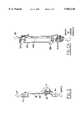
- FIG. 1is an exploded, perspective view of a visual signaling device embodying the invention
- FIG. 1Ais a view like FIG. 1 with some additional improvements
- FIG. 2is a top plan view of the device shown in FIG. 1A;
- FIG. 3is a view of a visual signaling device similar to that shown in FIG. 1, but having four instead of two modules;
- FIG. 4is a front elevational view of a visual signaling device having one module
- FIG. 5is a perspective view of the electrical, connections within each of the modules shown in the other figures.
- FIG. 5Ais a view similar to FIG. 5 of improved cabling and connections.
- a visual signaling devicehaving a plurality of modules 10 which are arranged in a vertical stack on a base 12.
- a cover 14is attached over the upper most module.
- Each modulehas a generally tri-liptic shape, as shown in FIG. 2.
- the tri-liptic shapeappears in cross section, the cross section being taken through a vertical axis 16 of the module and the stack.
- the tri-liptic shapehas three sides 18, 20 and 22 which are arcuate and are tangential to a circle having a radius equal to a perpendicular to each side where it is tangent to the circle.
- One of the sides 22is referred to herein, for the sake of simplifying the description, as the front side, while the other sides are referred to as forming back sides of the module.
- tri-liptic shapeflat edges are presented for providing a weather tight gasket seal. There is also a form factor which allows quick, easy and direct access for replacing lamps and/or circuits. Disassembly or removal of all modules located above the module to be relamped is not required. There is also greater stability than for a cylindrical structure.
- the triliptic shapeprovides a larger illumination area than a cylindrical stack of lights, and also provides a highly distinctive appearance.
- the back sides 18 and 20are preferably formed as a one piece part, as by molding it out of plastic material, which may be transparent, translucent, or striated to provide a light diffuser.
- the front side 22is a single part which also may be molded from plastic and also may be of the same material and appearance as the back side. When assembled together, the sides form the tri-liptic shape and provide an enclosure or shell containing a light source module 26 and an electrical assembly 28, also shown in FIG. 5.
- Each module 10has a top 32 and a bottom 34, which in the case of the top 32 and the bottom 34 of the rear sides of the module may be molded integrally with the sides 18 and 20 thereof.
- the front side 22has a top and a bottom, which is molded integrally with the face portion thereof.
- the back side of the moduleprovides the structural support which enables the modules to be stacked, as well as a housing for the light source module 26 and the electrical assembly 28.
- the top 32has two generally triangular openings 36 and 38 and may have two additional openings 40 and 42. Pins or protuberances (not shown) extend into these openings, from the bottom of the adjacent module of the stack, for alignment and for rigidly interconnecting modules to each other in the vertically stacked array. Other arrangements of openings (preferably at least three) are provided in the top 32 of each module.
- the protuberancesmay alternatively be in the bottoms and the openings in the top of adjacent module.
- the base 12, and also the coverhas pins or projections (not shown) complimentary to, and receivable in the openings 36, 38, 40 and 42 so as to connect the base and cover to the module or modules of the stack adjacent thereto.
- the modulesmay for example be 3 inches tall and a stack may contain up to five modules.
- a lip 45which defines a flat front edge of back side part of the module and into threaded holes in the projections or pins which extend through the openings 36 and 38, thereby rigidly connecting the modules.
- This lip 45presents a flat surface against which a gasket seal 50 mold to an edge face of the front 22. Screws 52 which extend through receiving holes 54 therefore provide clamping forces.
- the flat surfacesprovide for a tight weather seal when the parts of the module are put together.
- a seal 46is clamped between flat surfaces of the top 32 of the upper most module and an edge of the rim 58 of the cover 14.
- the electrical assembly 28Prior to attachment of the front side 22, the electrical assembly 28 is installed in the back part forming the sides 18 and 20.
- the electrical assembly as shown in FIG. 5may include either a ribbon cable or a strip of printed circuit board 60 (or 60a FIG. 5 A) containing leads which extend between upper and lower connectors 62 and 64. Slots 66 provide clearance for the connectors 62 and 64.
- the strip 60 of circuit boardmay be connected by tabs, straps or screws to the back part formed by the sides 18 and 20.
- An intermediate connector 68is attached at an ear 71 to form part of the electrical assembly.
- the electrical assemblymay be a straight board to which the connectors 62, 64 and 68 are attached along a side thereof.
- the intermediate connector 68receives a circuit board 70 on which a socket 72 for a lamp bulb 74 (shown by way of example as a halogen bulb) is received.
- a male connector 77is provided at an edge of the board.
- the boardhas a generally tri-liptic shape matching the shape of the module.
- Other electrical and mechanical componentssuch as a rotator in the case of a rotating reflector or strobe flashing circuits, may be attached to the board 70 and connected to the printed leads on the board 70.
- the boardis aligned by guides 76 and 78 which form a slot through which a board is inserted a sufficient distance so that its connector 77 is received and makes contact with the connector 68.
- the base module 12may have a threaded hole for receiving a pipe 80 which extends from the frame or apparatus on which the signaling device is mounted. Other forms of attachments, such as flanges on the base may alternatively be used.
- the base 12may contain an audible signaling device of the type known in the art, and in such event holes 82 may be provided through which the sound may emanate.
- FIG. 4shows one module installed on the base.
- FIG. 1shows two modules and FIG. 3 shows a stack of four modules.
- FIG. 1Ashows top 32 having multiple looped protuberances 42 instead of openings. These pins or protuberances extend into openings, from the bottom of the adjacent module of the stack, for alignment and rigidly interconnecting modules to each other in the vertically stacked array. Modules are then firmly attached the adjacent module below it via some type of fasteners that connect into the protuberances of the module below it. Screws, clips, rivets, or the fastening devices such as the interlocking "key" 83, provide a rigid connection between modules that can be disassembled. Cap or cover 14 can be attached using screw 85 via screw hole 84.
- the device of FIG. 1Auses the connector assembly of FIG. 5A uses the connector assembly of FIG. 5A. Parts described in connection with FIG. 5 are designated with the same numbers followed by an "a”.
Landscapes
- Engineering & Computer Science (AREA)
- Architecture (AREA)
- Civil Engineering (AREA)
- Structural Engineering (AREA)
- General Engineering & Computer Science (AREA)
- Mechanical Engineering (AREA)
- Fastening Of Light Sources Or Lamp Holders (AREA)
- Arrangement Of Elements, Cooling, Sealing, Or The Like Of Lighting Devices (AREA)
Abstract
Description
Claims (22)
Priority Applications (3)
| Application Number | Priority Date | Filing Date | Title |
|---|---|---|---|
| US09/028,230US5963126A (en) | 1997-02-27 | 1998-02-23 | Visual signaling device |
| AU64425/98AAU6442598A (en) | 1997-02-27 | 1998-02-26 | Visual signaling device |
| PCT/US1998/003858WO1998038613A1 (en) | 1997-02-27 | 1998-02-26 | Visual signaling device |
Applications Claiming Priority (2)
| Application Number | Priority Date | Filing Date | Title |
|---|---|---|---|
| US3829097P | 1997-02-27 | 1997-02-27 | |
| US09/028,230US5963126A (en) | 1997-02-27 | 1998-02-23 | Visual signaling device |
Publications (1)
| Publication Number | Publication Date |
|---|---|
| US5963126Atrue US5963126A (en) | 1999-10-05 |
Family
ID=26703453
Family Applications (1)
| Application Number | Title | Priority Date | Filing Date |
|---|---|---|---|
| US09/028,230Expired - LifetimeUS5963126A (en) | 1997-02-27 | 1998-02-23 | Visual signaling device |
Country Status (1)
| Country | Link |
|---|---|
| US (1) | US5963126A (en) |
Cited By (32)
| Publication number | Priority date | Publication date | Assignee | Title |
|---|---|---|---|---|
| US6384735B1 (en)* | 1998-11-26 | 2002-05-07 | Schneider Electric Industries Sa | Device for signaling conditions for electrical machines |
| US20030179099A1 (en)* | 2002-03-20 | 2003-09-25 | Perea Levi J. | Signaling device for annunciating a status of a monitored person or object |
| US20040046678A1 (en)* | 2002-09-10 | 2004-03-11 | Grady James A. | LED warning beacon |
| US20040085764A1 (en)* | 2002-10-30 | 2004-05-06 | Dialight Corporation | Beacon light with at least one light emitting diode and a method for retrofitting the beacon light onto an existing incandescent beacon light |
| US6839001B1 (en) | 2002-08-09 | 2005-01-04 | Walter E. Bonin | Safety strobe light |
| EP1239214A3 (en)* | 2001-03-10 | 2005-04-06 | Karl Jautz Elektrotechnische Spezialfabrik KG | Pillar-shaped indicator lamp |
| US20050200460A1 (en)* | 2004-03-11 | 2005-09-15 | Juergen Marquardt | Signaling device |
| US20070152842A1 (en)* | 2005-12-22 | 2007-07-05 | Fayfield Robert W | Micro-processor controlled indicator device |
| US20080242408A1 (en)* | 2007-03-28 | 2008-10-02 | Aristocrat Technologies Australia Pty, Ltd | Modular Visual Output Component |
| US20090214009A1 (en)* | 2008-02-22 | 2009-08-27 | Schuman Sr Richard J | Indicator apparatus for healthcare communication system |
| USD608673S1 (en)* | 2008-01-15 | 2010-01-26 | Gi.Bi.Di. S.R.L. | Signal lamp |
| US20100117852A1 (en)* | 2008-11-10 | 2010-05-13 | Kevin Matte | Multi-Function Flare Device for Populated Areas |
| US20100171629A1 (en)* | 2007-06-13 | 2010-07-08 | Myung Jin Lee | Signal tower and integration system using the same |
| US8193702B2 (en) | 2006-05-02 | 2012-06-05 | Switch Bulb Company, Inc. | Method of light dispersion and preferential scattering of certain wavelengths of light-emitting diodes and bulbs constructed therefrom |
| US8415695B2 (en) | 2007-10-24 | 2013-04-09 | Switch Bulb Company, Inc. | Diffuser for LED light sources |
| US8439528B2 (en) | 2007-10-03 | 2013-05-14 | Switch Bulb Company, Inc. | Glass LED light bulbs |
| US8547002B2 (en) | 2006-05-02 | 2013-10-01 | Switch Bulb Company, Inc. | Heat removal design for LED bulbs |
| US8591069B2 (en) | 2011-09-21 | 2013-11-26 | Switch Bulb Company, Inc. | LED light bulb with controlled color distribution using quantum dots |
| US20140015686A1 (en)* | 2012-07-10 | 2014-01-16 | Wistron Corporation | Active warning device for server and warning method thereof |
| US8702257B2 (en) | 2006-05-02 | 2014-04-22 | Switch Bulb Company, Inc. | Plastic LED bulb |
| US20160091187A1 (en)* | 2014-09-29 | 2016-03-31 | Werma Holding Gmbh + Co. Kg | Optical signalling device |
| US20160097493A1 (en)* | 2014-10-02 | 2016-04-07 | Taylor W. Anderson | Method and apparatus for a lighting assembly with an integrated auxiliary electronic component port |
| US20160203686A1 (en)* | 2015-01-12 | 2016-07-14 | Auer Signal Gmbh | Signalling device |
| USD765897S1 (en) | 2014-06-04 | 2016-09-06 | Archangel Design LLC | Wearable safety light |
| US9478108B2 (en) | 2008-11-10 | 2016-10-25 | Archangel Device Llc | Multi-directional, multi-functional, wearable safety lighting apparatus |
| USD782717S1 (en) | 2014-06-04 | 2017-03-28 | Archangel Device Llc | Safety light |
| USD791380S1 (en) | 2014-06-04 | 2017-07-04 | Archangel Device Llc | Mounting bracket for magnetically attracted lighting device |
| US9886832B2 (en)* | 2015-03-20 | 2018-02-06 | Federal Signal Corporation | Warning system devices |
| US9997031B2 (en) | 2015-07-20 | 2018-06-12 | Banner Engineering Corporation | Modular indicator |
| EP3343302A1 (en)* | 2016-12-28 | 2018-07-04 | Glial Technology | Housing for acquiring machine data |
| USD885624S1 (en) | 2018-08-10 | 2020-05-26 | Archangel Device Llc | Safety light |
| US10984636B2 (en) | 2015-07-20 | 2021-04-20 | Banner Engineering Corporation | Modular indicator |
Citations (8)
| Publication number | Priority date | Publication date | Assignee | Title |
|---|---|---|---|---|
| US3728708A (en)* | 1971-06-21 | 1973-04-17 | F Culbertson | Illuminated marker |
| US4468656A (en)* | 1981-06-24 | 1984-08-28 | Clifford Thomas J | Emergency signalling unit and alarm system for rescuing endangered workers |
| US4678450A (en)* | 1982-12-27 | 1987-07-07 | Life Light Systems | Toy light sword |
| US4959637A (en)* | 1989-08-07 | 1990-09-25 | National Safety Devices, Inc. | Emergency signaling device |
| US5081568A (en)* | 1991-05-28 | 1992-01-14 | Dong Lu J | Traffic police baton with means to indicate the direction in the night |
| US5103215A (en)* | 1990-10-10 | 1992-04-07 | Federal Signal Corporation | Device for signalling status of machines or processes |
| US5633623A (en)* | 1995-02-21 | 1997-05-27 | Campman; James P. | Personal indicator with light emission multiplying microprism array |
| US5697695A (en)* | 1997-01-27 | 1997-12-16 | Lin; Adam | Signal stick |
- 1998
- 1998-02-23USUS09/028,230patent/US5963126A/ennot_activeExpired - Lifetime
Patent Citations (8)
| Publication number | Priority date | Publication date | Assignee | Title |
|---|---|---|---|---|
| US3728708A (en)* | 1971-06-21 | 1973-04-17 | F Culbertson | Illuminated marker |
| US4468656A (en)* | 1981-06-24 | 1984-08-28 | Clifford Thomas J | Emergency signalling unit and alarm system for rescuing endangered workers |
| US4678450A (en)* | 1982-12-27 | 1987-07-07 | Life Light Systems | Toy light sword |
| US4959637A (en)* | 1989-08-07 | 1990-09-25 | National Safety Devices, Inc. | Emergency signaling device |
| US5103215A (en)* | 1990-10-10 | 1992-04-07 | Federal Signal Corporation | Device for signalling status of machines or processes |
| US5081568A (en)* | 1991-05-28 | 1992-01-14 | Dong Lu J | Traffic police baton with means to indicate the direction in the night |
| US5633623A (en)* | 1995-02-21 | 1997-05-27 | Campman; James P. | Personal indicator with light emission multiplying microprism array |
| US5697695A (en)* | 1997-01-27 | 1997-12-16 | Lin; Adam | Signal stick |
Non-Patent Citations (3)
| Title |
|---|
| Federal Signal Corporation Instruction Sheet for Models LSS 024 and LSS 120, Date Jun. 1995.* |
| Federal Signal Corporation Instruction Sheet for Models LSS-024 and LSS-120, Date Jun. 1995. |
| Sasaki Electric Corporation, Patlite Instruction Sheet, Jan. 1995.* |
Cited By (55)
| Publication number | Priority date | Publication date | Assignee | Title |
|---|---|---|---|---|
| US6384735B1 (en)* | 1998-11-26 | 2002-05-07 | Schneider Electric Industries Sa | Device for signaling conditions for electrical machines |
| EP1239214A3 (en)* | 2001-03-10 | 2005-04-06 | Karl Jautz Elektrotechnische Spezialfabrik KG | Pillar-shaped indicator lamp |
| US20030179099A1 (en)* | 2002-03-20 | 2003-09-25 | Perea Levi J. | Signaling device for annunciating a status of a monitored person or object |
| US6693514B2 (en)* | 2002-03-20 | 2004-02-17 | Rauland-Borg Corporation | Signaling device for annunciating a status of a monitored person or object |
| US6839001B1 (en) | 2002-08-09 | 2005-01-04 | Walter E. Bonin | Safety strobe light |
| US20040046678A1 (en)* | 2002-09-10 | 2004-03-11 | Grady James A. | LED warning beacon |
| US7158020B2 (en) | 2002-09-10 | 2007-01-02 | Grady Jr James A | LED warning beacon |
| US20040085764A1 (en)* | 2002-10-30 | 2004-05-06 | Dialight Corporation | Beacon light with at least one light emitting diode and a method for retrofitting the beacon light onto an existing incandescent beacon light |
| US7281821B2 (en)* | 2002-10-30 | 2007-10-16 | Dialight Corporation | Beacon light with at least one emitting diode and a method for retrofitting the beacon light onto an existing incandescent beacon light |
| US20050200460A1 (en)* | 2004-03-11 | 2005-09-15 | Juergen Marquardt | Signaling device |
| US7587178B2 (en)* | 2004-03-11 | 2009-09-08 | Werma Signaltechnik Gmbh & Co. Kg | Signaling device |
| US20070152842A1 (en)* | 2005-12-22 | 2007-07-05 | Fayfield Robert W | Micro-processor controlled indicator device |
| US7492276B2 (en)* | 2005-12-22 | 2009-02-17 | Banner Engineering Corporation | Micro-processor controlled indicator device |
| US8547002B2 (en) | 2006-05-02 | 2013-10-01 | Switch Bulb Company, Inc. | Heat removal design for LED bulbs |
| US8193702B2 (en) | 2006-05-02 | 2012-06-05 | Switch Bulb Company, Inc. | Method of light dispersion and preferential scattering of certain wavelengths of light-emitting diodes and bulbs constructed therefrom |
| US8853921B2 (en) | 2006-05-02 | 2014-10-07 | Switch Bulb Company, Inc. | Heat removal design for LED bulbs |
| US8704442B2 (en) | 2006-05-02 | 2014-04-22 | Switch Bulb Company, Inc. | Method of light dispersion and preferential scattering of certain wavelengths of light for light-emitting diodes and bulbs constructed therefrom |
| US8702257B2 (en) | 2006-05-02 | 2014-04-22 | Switch Bulb Company, Inc. | Plastic LED bulb |
| US8569949B2 (en) | 2006-05-02 | 2013-10-29 | Switch Bulb Company, Inc. | Method of light dispersion and preferential scattering of certain wavelengths of light-emitting diodes and bulbs constructed therefrom |
| US8075408B2 (en)* | 2007-03-28 | 2011-12-13 | Aristocrat Technologies Australia Pty. | Modular visual output component |
| US20100304861A1 (en)* | 2007-03-28 | 2010-12-02 | Aristocrat Technologies Australia Pty, Ltd | Modular visual output component |
| US20080242408A1 (en)* | 2007-03-28 | 2008-10-02 | Aristocrat Technologies Australia Pty, Ltd | Modular Visual Output Component |
| US20100171629A1 (en)* | 2007-06-13 | 2010-07-08 | Myung Jin Lee | Signal tower and integration system using the same |
| US8439528B2 (en) | 2007-10-03 | 2013-05-14 | Switch Bulb Company, Inc. | Glass LED light bulbs |
| US8752984B2 (en) | 2007-10-03 | 2014-06-17 | Switch Bulb Company, Inc. | Glass LED light bulbs |
| US8415695B2 (en) | 2007-10-24 | 2013-04-09 | Switch Bulb Company, Inc. | Diffuser for LED light sources |
| US8981405B2 (en) | 2007-10-24 | 2015-03-17 | Switch Bulb Company, Inc. | Diffuser for LED light sources |
| USD608673S1 (en)* | 2008-01-15 | 2010-01-26 | Gi.Bi.Di. S.R.L. | Signal lamp |
| US20090214009A1 (en)* | 2008-02-22 | 2009-08-27 | Schuman Sr Richard J | Indicator apparatus for healthcare communication system |
| US8384526B2 (en)* | 2008-02-22 | 2013-02-26 | Hill-Rom Services, Inc. | Indicator apparatus for healthcare communication system |
| US9478108B2 (en) | 2008-11-10 | 2016-10-25 | Archangel Device Llc | Multi-directional, multi-functional, wearable safety lighting apparatus |
| US10677450B2 (en) | 2008-11-10 | 2020-06-09 | Archangel Device Llc | Multi-directional, multi-functional wearable safety lighting apparatus |
| US20100117852A1 (en)* | 2008-11-10 | 2010-05-13 | Kevin Matte | Multi-Function Flare Device for Populated Areas |
| US10274190B2 (en) | 2008-11-10 | 2019-04-30 | Archangel Device Llc | Multi-directional, multi-functional wearable safety lighting apparatus |
| US8917187B2 (en) | 2008-11-10 | 2014-12-23 | 425, Inc. | Multi-function flare device for populated areas |
| US8591069B2 (en) | 2011-09-21 | 2013-11-26 | Switch Bulb Company, Inc. | LED light bulb with controlled color distribution using quantum dots |
| US8836531B2 (en)* | 2012-07-10 | 2014-09-16 | Wistron Corporation | Active warning device for server and warning method thereof |
| US20140015686A1 (en)* | 2012-07-10 | 2014-01-16 | Wistron Corporation | Active warning device for server and warning method thereof |
| USD782717S1 (en) | 2014-06-04 | 2017-03-28 | Archangel Device Llc | Safety light |
| USD791380S1 (en) | 2014-06-04 | 2017-07-04 | Archangel Device Llc | Mounting bracket for magnetically attracted lighting device |
| USD765897S1 (en) | 2014-06-04 | 2016-09-06 | Archangel Design LLC | Wearable safety light |
| US20160091187A1 (en)* | 2014-09-29 | 2016-03-31 | Werma Holding Gmbh + Co. Kg | Optical signalling device |
| US9945546B2 (en)* | 2014-09-29 | 2018-04-17 | Werma Holding Gmbh + Co. Kg | Optical signaling device |
| US20160097493A1 (en)* | 2014-10-02 | 2016-04-07 | Taylor W. Anderson | Method and apparatus for a lighting assembly with an integrated auxiliary electronic component port |
| US20190080571A1 (en)* | 2015-01-12 | 2019-03-14 | Auer Signal Gmbh | Signalling device |
| US10127779B2 (en)* | 2015-01-12 | 2018-11-13 | Auer Signal Gmbh | Signalling device |
| US10475304B2 (en)* | 2015-01-12 | 2019-11-12 | Auer Signal Gmbh | Signalling device |
| US20160203686A1 (en)* | 2015-01-12 | 2016-07-14 | Auer Signal Gmbh | Signalling device |
| US9886832B2 (en)* | 2015-03-20 | 2018-02-06 | Federal Signal Corporation | Warning system devices |
| US9997031B2 (en) | 2015-07-20 | 2018-06-12 | Banner Engineering Corporation | Modular indicator |
| US10984636B2 (en) | 2015-07-20 | 2021-04-20 | Banner Engineering Corporation | Modular indicator |
| US11580828B2 (en) | 2015-07-20 | 2023-02-14 | Banner Engineering Corporation | Modular indicator |
| USD1018347S1 (en) | 2015-07-20 | 2024-03-19 | Banner Engineering Corporation | Indicator light module |
| EP3343302A1 (en)* | 2016-12-28 | 2018-07-04 | Glial Technology | Housing for acquiring machine data |
| USD885624S1 (en) | 2018-08-10 | 2020-05-26 | Archangel Device Llc | Safety light |
Similar Documents
| Publication | Publication Date | Title |
|---|---|---|
| US5963126A (en) | Visual signaling device | |
| US6240665B1 (en) | Illuminated sign | |
| US8210725B2 (en) | Light bar | |
| CA2161940C (en) | Illuminated emergency sign utilizing led units | |
| US6142648A (en) | Emergency lighting unit/exit sign combination | |
| US4667277A (en) | Indicator lamp assembly | |
| US20130294059A1 (en) | Led light fixture | |
| US4471415A (en) | Mounting bar for spacing indicator lights | |
| US6499866B1 (en) | Emergency lighting unit/exit sign combination | |
| CN108895368A (en) | A kind of assembled lamps and lanterns | |
| CN205782219U (en) | Bar shape LED lamp and linear cascade LED illumination System | |
| WO1998038613A1 (en) | Visual signaling device | |
| CN208381956U (en) | A kind of assembled lamps and lanterns | |
| US4988986A (en) | Display module and multiple unit display constructed of such display modules | |
| WO1998038613B1 (en) | Visual signaling device | |
| CN107435838B (en) | Strip-shaped LED lamp and linear cascading LED lighting system | |
| US20120113643A1 (en) | Led lamp | |
| CN210374059U (en) | Novel fan heater | |
| CN211789781U (en) | Ceiling lamp | |
| CN106931365A (en) | A kind of emergency LED Down lamp | |
| CN216844228U (en) | Downlight with double installation structure | |
| CN221122019U (en) | Lamp set | |
| CN217208990U (en) | Lens assembly and lamp | |
| CN216619699U (en) | Panel light | |
| CN212256817U (en) | LED indicating lamp board |
Legal Events
| Date | Code | Title | Description |
|---|---|---|---|
| AS | Assignment | Owner name:STAR HEADLIGHT AND LANTERN CO., INC., NEW YORK Free format text:ASSIGNMENT OF ASSIGNORS INTEREST;ASSIGNORS:KARLIN, JAMES H.;VUKOSIC, STEPHEN T.;MASTIN, MICHAEL F.;REEL/FRAME:009017/0186;SIGNING DATES FROM 19980212 TO 19980213 | |
| STCF | Information on status: patent grant | Free format text:PATENTED CASE | |
| FEPP | Fee payment procedure | Free format text:PAYOR NUMBER ASSIGNED (ORIGINAL EVENT CODE: ASPN); ENTITY STATUS OF PATENT OWNER: SMALL ENTITY | |
| FPAY | Fee payment | Year of fee payment:4 | |
| FPAY | Fee payment | Year of fee payment:8 | |
| FPAY | Fee payment | Year of fee payment:12 | |
| AS | Assignment | Owner name:JPMORGAN CHASE BANK, N.A., OHIO Free format text:ASSIGNMENT OF ASSIGNORS INTEREST;ASSIGNOR:STAR SAFETY TECHNOLOGIES, LLC;REEL/FRAME:064228/0688 Effective date:20230603 | |
| AS | Assignment | Owner name:JPMORGAN CHASE BANK, N.A., OHIO Free format text:CORRECTIVE ASSIGNMENT TO CORRECT THE NATURE OF CONVEYANCE PREVIOUSLY RECORDED AT REEL: 064228 FRAME: 0688. ASSIGNOR(S) HEREBY CONFIRMS THE SECURITY INTEREST;ASSIGNOR:STAR SAFETY TECHNOLOGIES, LLC;REEL/FRAME:064274/0456 Effective date:20230603 |