US5963017A - Calibration of the battery device for a portable computer system - Google Patents
Calibration of the battery device for a portable computer systemDownload PDFInfo
- Publication number
- US5963017A US5963017AUS09/097,088US9708898AUS5963017AUS 5963017 AUS5963017 AUS 5963017AUS 9708898 AUS9708898 AUS 9708898AUS 5963017 AUS5963017 AUS 5963017A
- Authority
- US
- United States
- Prior art keywords
- battery
- computer system
- parallel port
- port interface
- capacity
- Prior art date
- Legal status (The legal status is an assumption and is not a legal conclusion. Google has not performed a legal analysis and makes no representation as to the accuracy of the status listed.)
- Expired - Lifetime
Links
- 238000000034methodMethods0.000abstractdescription11
- 238000001514detection methodMethods0.000description7
- 230000003247decreasing effectEffects0.000description2
- 230000006870functionEffects0.000description1
- 230000007704transitionEffects0.000description1
Images

Classifications
- G—PHYSICS
- G01—MEASURING; TESTING
- G01R—MEASURING ELECTRIC VARIABLES; MEASURING MAGNETIC VARIABLES
- G01R31/00—Arrangements for testing electric properties; Arrangements for locating electric faults; Arrangements for electrical testing characterised by what is being tested not provided for elsewhere
- G01R31/36—Arrangements for testing, measuring or monitoring the electrical condition of accumulators or electric batteries, e.g. capacity or state of charge [SoC]
- G01R31/3644—Constructional arrangements
- G01R31/3648—Constructional arrangements comprising digital calculation means, e.g. for performing an algorithm
- G—PHYSICS
- G01—MEASURING; TESTING
- G01R—MEASURING ELECTRIC VARIABLES; MEASURING MAGNETIC VARIABLES
- G01R31/00—Arrangements for testing electric properties; Arrangements for locating electric faults; Arrangements for electrical testing characterised by what is being tested not provided for elsewhere
- G01R31/36—Arrangements for testing, measuring or monitoring the electrical condition of accumulators or electric batteries, e.g. capacity or state of charge [SoC]
- G01R31/367—Software therefor, e.g. for battery testing using modelling or look-up tables
- G—PHYSICS
- G01—MEASURING; TESTING
- G01R—MEASURING ELECTRIC VARIABLES; MEASURING MAGNETIC VARIABLES
- G01R35/00—Testing or calibrating of apparatus covered by the other groups of this subclass
- G01R35/005—Calibrating; Standards or reference devices, e.g. voltage or resistance standards, "golden" references
- H—ELECTRICITY
- H02—GENERATION; CONVERSION OR DISTRIBUTION OF ELECTRIC POWER
- H02J—CIRCUIT ARRANGEMENTS OR SYSTEMS FOR SUPPLYING OR DISTRIBUTING ELECTRIC POWER; SYSTEMS FOR STORING ELECTRIC ENERGY
- H02J7/00—Circuit arrangements for charging or depolarising batteries or for supplying loads from batteries
- H02J7/0069—Charging or discharging for charge maintenance, battery initiation or rejuvenation
- Y—GENERAL TAGGING OF NEW TECHNOLOGICAL DEVELOPMENTS; GENERAL TAGGING OF CROSS-SECTIONAL TECHNOLOGIES SPANNING OVER SEVERAL SECTIONS OF THE IPC; TECHNICAL SUBJECTS COVERED BY FORMER USPC CROSS-REFERENCE ART COLLECTIONS [XRACs] AND DIGESTS
- Y10—TECHNICAL SUBJECTS COVERED BY FORMER USPC
- Y10S—TECHNICAL SUBJECTS COVERED BY FORMER USPC CROSS-REFERENCE ART COLLECTIONS [XRACs] AND DIGESTS
- Y10S320/00—Electricity: battery or capacitor charging or discharging
- Y10S320/18—Indicator or display
- Y10S320/21—State of charge of battery
Definitions
- the inventionrelates to a capacity calibration apparatus for the battery of a portable computer system.
- a battery state detection chipi.e. bq 2092 within the battery pack of a portable computer system.
- This chiprecords various states of the battery, including battery voltage, temperature, charge/discharge current, capacity, and version, etc.
- the unit of the capacity of a batteryis denoted as milli-ampere/hour, i.e. MAH. It is known that, before a new battery is used, it is required to perform an initialization operation to the values of the state within the chip.
- the detection chipprovides accurate readings during life time of the battery only when this initialization operation is accurately done.
- the detection chip of the batteryEach time the battery experiences a discharge operation from a full charge capacity condition, this DCR counter starts to count.
- the detection chip of the batteryalso includes a full-charge-capacity (FCC) register for storing the maximum capacity value of the battery which may be obtained from DCR counter.
- FCCfull-charge-capacity
- the calibration apparatus of the present invention together with a charge/discharge procedureis aimed to accomplish the initialization operation mentioned above.
- a capacity calibration apparatus for the battery of a portable computer systemis provided.
- the portable computer systemincludes a main board circuit, a processor unit, a display unit, a power-supply board circuit, a battery and a parallel port interface.
- the capacity calibration apparatusincludes a standard parallel port interface and a control circuit.
- the standard parallel port interfaceis connected to the parallel port interface of the computer system. Via the parallel port interface, the computer system outputs at least one control signal to the capacity calibration apparatus.
- the capacity calibration apparatusselectively outputs the alternating current supply to the power-supply board circuit in order to proceed a charge/discharge procedure of a predetermined type such that the capacity value of the battery is initialized.
- control circuitincludes a logic circuit, a relay and a switch circuit.
- the logic circuitis responsive to the control signal and outputs a switch signal.
- the relayhas a first terminal and a second terminal. The first terminal inputs the alternating current supply.
- the switch circuitis responsive to the switch signal and controls turn-on or turn-off of the relay such that the second terminal of the relay selectively outputs the alternating current supply.
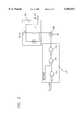
- FIG. 1illustrates the invention in functional blocks.
- FIG. 2illustrates one embodiment of the control circuit in FIG. 1.
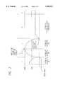
- FIG. 3illustrates a charge/discharge procedure performed by the invention to achieve the calibration of the battery capacity.
- a portable computer system 100 of conventional typeincludes a parallel port interface 102 (female connector), a main board circuit 104, a battery power supply 106 and a power-supply board circuit 108.
- the power-supply board circuit 108receives an alternating current supply AC-OUT, the alternating current supply is used to operate the main board circuit 104 and other elements in the system.
- the power-supply board circuit 108outputs a control signal 110 to perform a charge operation to the battery 106.
- the state values associated with the batteryi.e. the voltage value, temperature, etc., are sent to the main board circuit 104 via the signal lines 114.
- the signal lines 114are the System Management (SM) Bus of the system.
- the main board circuit 104communicates with the parallel port interface 102 via a standard parallel port signal lines 140.
- the portable computer systemmay include a storage device 300, i.e. a HDD or FDD, for storing an Utility which is to be executed in the system by a well known manner.
- the inventionprovides a capacity calibration apparatus 200 connected to the parallel port interface 102 of the computer system 100. Along with a charge/discharge utility program pre-stored in the storage device 300, the invention performs a battery capacity calibration over the battery 106.
- the calibration apparatus 200includes a control circuit 204 and a standard parallel port interface 202 (male connector).
- the interface 102 on the side of the computer system 100 and the interface 202 on the side of calibration apparatus 200communicates with each other via the signal lines 120.
- the capacity calibration apparatus 200inputs an alternating current supply AC-IN and, under the control of the control signals 206 from the interface 202, selectively outputs the alternating current supply AC-OUT to the power-supply board circuit 108 of the computer system 100. Therefore, the power-supply board circuit 108 is turned on and off alternately to accomplish the charge/discharge operation to the battery 106.
- the control circuit 204includes a relay 206, a switch device 208 and logic circuit 210.
- the switch device 208controls the ON/OFF of the relay 206.
- the A terminal of the relay 206inputs the alternating current supply AC-IN, and the B terminal outputs the alternating current supply AC-OUT.
- the logic circuit 210includes NAND function gates 212, 214 and 216.
- the two inputs of the NAND gate 212respectively input the BA -- AS signal that comes from the B4 pin of the parallel port interface 202.
- One input signal of the NAND gate 214is A8 -- D6 signal that comes from A8 pin of the parallel port interface 202.
- the other input signal to the gate 214is the output signal from the NAND gate 212.
- the output signal of the NAND gate 214is the input signal to the inputs of the NAND gate 216 respectively.
- A8 -- D6 signalis logic HIGH and B4 -- AS signal is logic LOW
- the switch device 208conducts prohibiting the B terminal from outputting the AC-OUT supply.
- the switch device 208is turned off which allows the B terminal outputting the AC-OUT supply.
- the main board circuit 104controls the states of the A8 -- D6, B4 -- AS signals respectively.
- the alternating current supply AC-OUTis selectively output to accomplish the charge/discharge procedure as illustrated in FIG. 3. It is to be noted that, other charge/discharge procedures equivalent to that shown in FIG. 3 are likely to persons skilled in the arts to still accomplish the object of the invention with the provision of the calibration apparatus of the invention.
- the preferred embodiment of the charge/discharge procedure of the inventionmay be understood by referring to a curve in FIG. 3 which indicates capacity-versus-time.
- 100%represents the capacity of the battery reaches the nominal max. capacity while 50% indicates the battery capacity reaches one half of the nominal max. capacity.
- five stagesare disclosed.
- the inventionperforms a discharge action involving turn-ON of the computer system 100 and turn-OFF of the capacity calibration apparatus 200.
- the battery 106discharges and the capacity curve thereof experiences a parabolic decreasing phenomenon.
- the main board circuit 104may detect whether the battery capacity reaches a predetermined value, i.e. an EDVI value of around 13.8 volts.
- the inventionturns OFF the computer system 100 and turns ON the capacity calibration apparatus 200.
- This actionallows the AC-OUT supply enter the power-supply board circuit 108 such that the power-supply board circuit 108 charges to the battery 106 in the second stage.
- the inventionperiodically wakes up the computer system 100 to find out whether the battery capacity reaches one hundred percent via the System Management bus 114.
- the inventionimmediately ends the second stage and commences the third stage.
- the inventionthen turns ON the computer system 100 and turns OFF the calibration apparatus 200 again to perform a discharge procedure from a full charge capacity condition. Accordingly, the capacity curve thereof experiences a parabolic decreasing phenomenon again.
- the detection chip of the battery 106includes a full-charge-capacity (FCC) register for storing the maximum capacity value of the battery.
- FCCfull-charge-capacity
- the detection chip of the battery 106stores the value within the DCR counter into the FCC register at the end of the third stage such that the initialization with respect to the capacity value is accomplished.
- stages 4, 5 in FIG. 3are not recited here since they are well known Run-In procedure irrelevant to the object of the present invention.
Landscapes
- Physics & Mathematics (AREA)
- General Physics & Mathematics (AREA)
- Engineering & Computer Science (AREA)
- Power Engineering (AREA)
- Power Sources (AREA)
Abstract
Description
The invention relates to a capacity calibration apparatus for the battery of a portable computer system.
There is provided a battery state detection chip, i.e. bq 2092, within the battery pack of a portable computer system. This chip records various states of the battery, including battery voltage, temperature, charge/discharge current, capacity, and version, etc. In general, the unit of the capacity of a battery is denoted as milli-ampere/hour, i.e. MAH. It is known that, before a new battery is used, it is required to perform an initialization operation to the values of the state within the chip. The detection chip provides accurate readings during life time of the battery only when this initialization operation is accurately done.
It is well known a DCR counter is provided in the detection chip of the battery. Each time the battery experiences a discharge operation from a full charge capacity condition, this DCR counter starts to count. In addition, the detection chip of the battery also includes a full-charge-capacity (FCC) register for storing the maximum capacity value of the battery which may be obtained from DCR counter.
The calibration apparatus of the present invention together with a charge/discharge procedure is aimed to accomplish the initialization operation mentioned above.
A capacity calibration apparatus for the battery of a portable computer system is provided.
The portable computer system includes a main board circuit, a processor unit, a display unit, a power-supply board circuit, a battery and a parallel port interface.
The capacity calibration apparatus includes a standard parallel port interface and a control circuit. The standard parallel port interface is connected to the parallel port interface of the computer system. Via the parallel port interface, the computer system outputs at least one control signal to the capacity calibration apparatus. The capacity calibration apparatus selectively outputs the alternating current supply to the power-supply board circuit in order to proceed a charge/discharge procedure of a predetermined type such that the capacity value of the battery is initialized.
In a preferred embodiment, the control circuit includes a logic circuit, a relay and a switch circuit.
The logic circuit is responsive to the control signal and outputs a switch signal. The relay has a first terminal and a second terminal. The first terminal inputs the alternating current supply. The switch circuit is responsive to the switch signal and controls turn-on or turn-off of the relay such that the second terminal of the relay selectively outputs the alternating current supply.
The details and merits of the invention may be best understood by the following recitations along with the appended drawings.
FIG. 1 illustrates the invention in functional blocks.
FIG. 2 illustrates one embodiment of the control circuit in FIG. 1.
FIG. 3 illustrates a charge/discharge procedure performed by the invention to achieve the calibration of the battery capacity.
As shown in FIG. 1, aportable computer system 100 of conventional type includes a parallel port interface 102 (female connector), amain board circuit 104, abattery power supply 106 and a power-supply board circuit 108. In normal operation under which the power-supply board circuit 108 receives an alternating current supply AC-OUT, the alternating current supply is used to operate themain board circuit 104 and other elements in the system. Furthermore, the power-supply board circuit 108, during the normal operation, outputs acontrol signal 110 to perform a charge operation to thebattery 106. The state values associated with the battery, i.e. the voltage value, temperature, etc., are sent to themain board circuit 104 via thesignal lines 114. As an embodiment, thesignal lines 114 are the System Management (SM) Bus of the system. In addition, themain board circuit 104 communicates with theparallel port interface 102 via a standard parallelport signal lines 140. Other than above, the portable computer system may include astorage device 300, i.e. a HDD or FDD, for storing an Utility which is to be executed in the system by a well known manner.
Further referring to FIG. 1, the invention provides acapacity calibration apparatus 200 connected to theparallel port interface 102 of thecomputer system 100. Along with a charge/discharge utility program pre-stored in thestorage device 300, the invention performs a battery capacity calibration over thebattery 106.
As shown, thecalibration apparatus 200 includes acontrol circuit 204 and a standard parallel port interface 202 (male connector). During the calibration operation of the invention, theinterface 102 on the side of thecomputer system 100 and theinterface 202 on the side ofcalibration apparatus 200 communicates with each other via thesignal lines 120. Thecapacity calibration apparatus 200 inputs an alternating current supply AC-IN and, under the control of thecontrol signals 206 from theinterface 202, selectively outputs the alternating current supply AC-OUT to the power-supply board circuit 108 of thecomputer system 100. Therefore, the power-supply board circuit 108 is turned on and off alternately to accomplish the charge/discharge operation to thebattery 106.
As illustrated by an embodiment shown in FIG. 2, thecontrol circuit 204 includes arelay 206, aswitch device 208 andlogic circuit 210. Theswitch device 208 controls the ON/OFF of therelay 206. The A terminal of therelay 206 inputs the alternating current supply AC-IN, and the B terminal outputs the alternating current supply AC-OUT. Thelogic circuit 210 includesNAND function gates NAND gate 212 respectively input the BA-- AS signal that comes from the B4 pin of theparallel port interface 202. One input signal of theNAND gate 214 is A8-- D6 signal that comes from A8 pin of theparallel port interface 202. The other input signal to thegate 214 is the output signal from theNAND gate 212. The output signal of theNAND gate 214 is the input signal to the inputs of theNAND gate 216 respectively. As a result, as A8-- D6 signal is logic HIGH and B4-- AS signal is logic LOW, theswitch device 208 conducts prohibiting the B terminal from outputting the AC-OUT supply. Under conditions of other values for A8-- D6, B4-- AS signals, theswitch device 208 is turned off which allows the B terminal outputting the AC-OUT supply.
As a charge/discharge procedure of the invention stored in thestorage device 300 is loaded into the memory on themain board circuit 104 for execution, themain board circuit 104, via thelines 140, theinterface 102, theinterface 202, controls the states of the A8-- D6, B4-- AS signals respectively. As a result, the alternating current supply AC-OUT is selectively output to accomplish the charge/discharge procedure as illustrated in FIG. 3. It is to be noted that, other charge/discharge procedures equivalent to that shown in FIG. 3 are likely to persons skilled in the arts to still accomplish the object of the invention with the provision of the calibration apparatus of the invention.
The preferred embodiment of the charge/discharge procedure of the invention may be understood by referring to a curve in FIG. 3 which indicates capacity-versus-time. In the figure, 100% represents the capacity of the battery reaches the nominal max. capacity while 50% indicates the battery capacity reaches one half of the nominal max. capacity. Also in the figure, five stages are disclosed. In the first stage, the invention performs a discharge action involving turn-ON of thecomputer system 100 and turn-OFF of thecapacity calibration apparatus 200. In such condition, thebattery 106 discharges and the capacity curve thereof experiences a parabolic decreasing phenomenon. During this discharge period, via theSystem Management bus 114, themain board circuit 104 may detect whether the battery capacity reaches a predetermined value, i.e. an EDVI value of around 13.8 volts. As this predetermined value is reached, the invention turns OFF thecomputer system 100 and turns ON thecapacity calibration apparatus 200. This action allows the AC-OUT supply enter the power-supply board circuit 108 such that the power-supply board circuit 108 charges to thebattery 106 in the second stage. During the second stage of the procedure, the invention periodically wakes up thecomputer system 100 to find out whether the battery capacity reaches one hundred percent via theSystem Management bus 114. Once the set condition is met, the invention immediately ends the second stage and commences the third stage. In the third stage, the invention then turns ON thecomputer system 100 and turns OFF thecalibration apparatus 200 again to perform a discharge procedure from a full charge capacity condition. Accordingly, the capacity curve thereof experiences a parabolic decreasing phenomenon again.
It is recited above that there is a DCR counter in the detection chip of thebattery 106. Each time the battery experiences discharge operation from a full charge capacity condition, the DCR counter starts to count. That is, as thebattery 106 starts to discharge from the beginning of the third stage, the DCR counter starts to count. The detection chip of thebattery 106 includes a full-charge-capacity (FCC) register for storing the maximum capacity value of the battery. When themain board circuit 104 detects the predetermined EDVI value is reached during the third stage, the invention immediately ends the third stage and enters the fourth stage. At the moment of transition from the third to fourth stage, the value within the DCR counter represents the full charge capacity. Accordingly, the detection chip of thebattery 106 stores the value within the DCR counter into the FCC register at the end of the third stage such that the initialization with respect to the capacity value is accomplished.
The details ofstages 4, 5 in FIG. 3 are not recited here since they are well known Run-In procedure irrelevant to the object of the present invention.
Claims (2)
1. A calibration apparatus for a battery device of a portable computer system, which includes a parallel port interface, a main board circuit, the battery and a power-supply board circuit, the calibration apparatus inputting an alternating current supply, comprising:
a standard parallel port interface coupled to the parallel port interface of the portable computer system for generating at least a control signal;
a control circuit, inputting the control signal, for selectively outputting the alternating current supply to the power-supply board circuit to perform charge/discharge operation of a predetermined type.
2. The calibration apparatus of claim 1, wherein the control circuit comprises:
a logic circuit, responsive to the control signal, for outputting a switch signal;
a relay having a first terminal and a second terminal, the first terminal inputting said alternating current supply;
means, responsive to the switch signal, for controlling turn-on or turn-off of the relay such that the second terminal of the relay selectively outputting the alternating current supply.
Applications Claiming Priority (2)
| Application Number | Priority Date | Filing Date | Title |
|---|---|---|---|
| TW087204812UTW363771U (en) | 1998-04-01 | 1998-04-01 | Portable calibration structure for computer battery capacity |
| TW87204812 | 1998-04-01 |
Publications (1)
| Publication Number | Publication Date |
|---|---|
| US5963017Atrue US5963017A (en) | 1999-10-05 |
Family
ID=21633306
Family Applications (1)
| Application Number | Title | Priority Date | Filing Date |
|---|---|---|---|
| US09/097,088Expired - LifetimeUS5963017A (en) | 1998-04-01 | 1998-06-12 | Calibration of the battery device for a portable computer system |
Country Status (2)
| Country | Link |
|---|---|
| US (1) | US5963017A (en) |
| TW (1) | TW363771U (en) |
Cited By (5)
| Publication number | Priority date | Publication date | Assignee | Title |
|---|---|---|---|---|
| US6630814B2 (en) | 2000-12-19 | 2003-10-07 | Telefonaktiebolaget Lm Ericsson (Publ) | Method and apparatus for calibrating a rechargeable battery |
| US20050117050A1 (en)* | 2003-12-01 | 2005-06-02 | Nikon Corporation | Battery, camera and camera system |
| US6936221B1 (en)* | 1998-07-24 | 2005-08-30 | Therox, Inc. | Method of forming gas-enriched fluid |
| US7622895B1 (en) | 2006-03-23 | 2009-11-24 | Griffin Technology, Inc. | Power level display calibration device |
| US20110154005A1 (en)* | 2009-12-18 | 2011-06-23 | Landry John A | Automated battery calibration |
Citations (9)
| Publication number | Priority date | Publication date | Assignee | Title |
|---|---|---|---|---|
| US3796940A (en)* | 1971-12-27 | 1974-03-12 | Bogue J | Battery power supply,maintenance free |
| US4734635A (en)* | 1986-09-26 | 1988-03-29 | Motorola, Inc. | Microprocessor controlled battery reconditioner for portable radio transceivers |
| US5196779A (en)* | 1989-11-16 | 1993-03-23 | Alexander Manufacturing Company | Battery maintenance system |
| US5541489A (en)* | 1994-12-15 | 1996-07-30 | Intel Corporation | Smart battery power availability feature based on battery-specific characteristics |
| US5691742A (en)* | 1995-05-24 | 1997-11-25 | Dell U.S.A., L.P. | Software battery gauge for portable computers |
| US5698961A (en)* | 1995-09-13 | 1997-12-16 | Hm Electronics, Inc. | Battery analyzer/conditioner system and method of using same |
| US5705910A (en)* | 1995-02-15 | 1998-01-06 | Fujitsu Limited | Electric charge/discharge control device and electric charge/discharge control method in a system using the same device |
| US5793188A (en)* | 1994-03-22 | 1998-08-11 | Braun Aktiengesellschaft | Method of conditioning accumulators fixedly mounted in an apparatus and a device therefor |
| US5890780A (en)* | 1996-10-07 | 1999-04-06 | Nec Corporation | Power supply switching apparatus with protection function for supplying power to an electronic circuit via an external power source or an internal power supply source |
- 1998
- 1998-04-01TWTW087204812Upatent/TW363771U/enunknown
- 1998-06-12USUS09/097,088patent/US5963017A/ennot_activeExpired - Lifetime
Patent Citations (9)
| Publication number | Priority date | Publication date | Assignee | Title |
|---|---|---|---|---|
| US3796940A (en)* | 1971-12-27 | 1974-03-12 | Bogue J | Battery power supply,maintenance free |
| US4734635A (en)* | 1986-09-26 | 1988-03-29 | Motorola, Inc. | Microprocessor controlled battery reconditioner for portable radio transceivers |
| US5196779A (en)* | 1989-11-16 | 1993-03-23 | Alexander Manufacturing Company | Battery maintenance system |
| US5793188A (en)* | 1994-03-22 | 1998-08-11 | Braun Aktiengesellschaft | Method of conditioning accumulators fixedly mounted in an apparatus and a device therefor |
| US5541489A (en)* | 1994-12-15 | 1996-07-30 | Intel Corporation | Smart battery power availability feature based on battery-specific characteristics |
| US5705910A (en)* | 1995-02-15 | 1998-01-06 | Fujitsu Limited | Electric charge/discharge control device and electric charge/discharge control method in a system using the same device |
| US5691742A (en)* | 1995-05-24 | 1997-11-25 | Dell U.S.A., L.P. | Software battery gauge for portable computers |
| US5698961A (en)* | 1995-09-13 | 1997-12-16 | Hm Electronics, Inc. | Battery analyzer/conditioner system and method of using same |
| US5890780A (en)* | 1996-10-07 | 1999-04-06 | Nec Corporation | Power supply switching apparatus with protection function for supplying power to an electronic circuit via an external power source or an internal power supply source |
Cited By (7)
| Publication number | Priority date | Publication date | Assignee | Title |
|---|---|---|---|---|
| US6936221B1 (en)* | 1998-07-24 | 2005-08-30 | Therox, Inc. | Method of forming gas-enriched fluid |
| US6630814B2 (en) | 2000-12-19 | 2003-10-07 | Telefonaktiebolaget Lm Ericsson (Publ) | Method and apparatus for calibrating a rechargeable battery |
| US20050117050A1 (en)* | 2003-12-01 | 2005-06-02 | Nikon Corporation | Battery, camera and camera system |
| US7911531B2 (en)* | 2003-12-01 | 2011-03-22 | Nikon Corporation | Battery, camera and camera system |
| US7622895B1 (en) | 2006-03-23 | 2009-11-24 | Griffin Technology, Inc. | Power level display calibration device |
| US20110154005A1 (en)* | 2009-12-18 | 2011-06-23 | Landry John A | Automated battery calibration |
| US8443212B2 (en)* | 2009-12-18 | 2013-05-14 | Hewlett-Packard Development Company, L.P. | Automated battery calibration |
Also Published As
| Publication number | Publication date |
|---|---|
| TW363771U (en) | 1999-07-01 |
Similar Documents
| Publication | Publication Date | Title |
|---|---|---|
| KR100824828B1 (en) | Smart battery verification method and related system by measuring input charging voltage | |
| US5861812A (en) | Battery pack wakeup | |
| KR100966871B1 (en) | Charge / discharge protection circuit, battery pack with built-in charge / discharge protection circuit, and electronic device using the battery pack | |
| US6501249B1 (en) | Battery management system | |
| US5903137A (en) | Battery pack with single charge inhibit/regulator transistor | |
| US7790307B2 (en) | Structure and operation method of battery pack | |
| US20200067326A1 (en) | Rechargeable battery protection integrated circuit, rechargeable battery protection device, and battery pack | |
| US5929603A (en) | Apparatus for preventing over-discharge | |
| US6051956A (en) | Rechargeable battery pack with pre-end signal output terminal and electronic device containing rechargeable battery pack | |
| US5764028A (en) | Battery pack with single charge-inhibit/regulator transistor | |
| US6060863A (en) | Charge and discharge control circuit and chargeable power supply unit | |
| CN108628431A (en) | Electronic equipment and its certainly energy consumption control circuit | |
| US20200083725A1 (en) | Hibernate mode for battery pack protection circuitry | |
| US6522104B1 (en) | Method and apparatus for measurement of charge in a battery | |
| CN117458668B (en) | Battery protection circuit, battery protection board and electronic equipment | |
| US7039150B1 (en) | Serial interface for a battery management system | |
| US6798171B2 (en) | Battery state monitoring circuit and battery device | |
| KR20050020406A (en) | Apparatus for controlling power in complex mobile terminal | |
| US5963017A (en) | Calibration of the battery device for a portable computer system | |
| US7449864B2 (en) | Apparatus and method for controlling battery discharge between internal battery and external battery | |
| US20070241618A1 (en) | Intelligent Battery Switching Circuit Block for Portable Devices | |
| CN112636308B (en) | Battery short-circuit protection method, device, system, battery and storage medium | |
| CN105896662A (en) | Single-port mobile power control circuit and control method thereof | |
| KR0145442B1 (en) | Charging control method of battery charger | |
| JP2990591B2 (en) | Rechargeable battery pack |
Legal Events
| Date | Code | Title | Description |
|---|---|---|---|
| AS | Assignment | Owner name:ASUSTEK COMPUTER INC., TAIWAN Free format text:ASSIGNMENT OF ASSIGNORS INTEREST;ASSIGNORS:YEH, KUA-CHI;CHANG, LI-HUI;REEL/FRAME:009268/0365 Effective date:19980101 | |
| STCF | Information on status: patent grant | Free format text:PATENTED CASE | |
| FPAY | Fee payment | Year of fee payment:4 | |
| FPAY | Fee payment | Year of fee payment:8 | |
| FEPP | Fee payment procedure | Free format text:PAYOR NUMBER ASSIGNED (ORIGINAL EVENT CODE: ASPN); ENTITY STATUS OF PATENT OWNER: LARGE ENTITY | |
| AS | Assignment | Owner name:PEGATRON CORPORATION,TAIWAN Free format text:ASSIGNMENT OF ASSIGNORS INTEREST;ASSIGNOR:ASUSTEK COMPUTER INC.;REEL/FRAME:024218/0450 Effective date:20100401 | |
| FPAY | Fee payment | Year of fee payment:12 |