US5961930A - Integrated micro-ceramic chemical plant with insertable reaction chambers and micro-filters - Google Patents
Integrated micro-ceramic chemical plant with insertable reaction chambers and micro-filtersDownload PDFInfo
- Publication number
- US5961930A US5961930AUS08/951,179US95117997AUS5961930AUS 5961930 AUS5961930 AUS 5961930AUS 95117997 AUS95117997 AUS 95117997AUS 5961930 AUS5961930 AUS 5961930A
- Authority
- US
- United States
- Prior art keywords
- micro
- ceramic
- reaction chamber
- chemical plant
- catalytic reaction
- Prior art date
- Legal status (The legal status is an assumption and is not a legal conclusion. Google has not performed a legal analysis and makes no representation as to the accuracy of the status listed.)
- Expired - Lifetime
Links
Images


Classifications
- B—PERFORMING OPERATIONS; TRANSPORTING
- B01—PHYSICAL OR CHEMICAL PROCESSES OR APPARATUS IN GENERAL
- B01J—CHEMICAL OR PHYSICAL PROCESSES, e.g. CATALYSIS OR COLLOID CHEMISTRY; THEIR RELEVANT APPARATUS
- B01J19/00—Chemical, physical or physico-chemical processes in general; Their relevant apparatus
- B01J19/0093—Microreactors, e.g. miniaturised or microfabricated reactors
- B—PERFORMING OPERATIONS; TRANSPORTING
- B01—PHYSICAL OR CHEMICAL PROCESSES OR APPARATUS IN GENERAL
- B01J—CHEMICAL OR PHYSICAL PROCESSES, e.g. CATALYSIS OR COLLOID CHEMISTRY; THEIR RELEVANT APPARATUS
- B01J2219/00—Chemical, physical or physico-chemical processes in general; Their relevant apparatus
- B01J2219/00781—Aspects relating to microreactors
- B01J2219/00891—Feeding or evacuation
Definitions
- the present inventionrelates to an integrated micro-ceramic chemical plant and to improved reaction and micro-filtering used in producing and separating such chemicals and products of chemical reactions.
- Micro-engineeringis a rapidly growing field which is liable to impact on many applications over the coming years.
- Three-dimensional micro-engineered devices and systems involving silicon planar technologycan be produced with features from one to a few hundred microns having tolerances in micron or as small as submicron level.
- Most of the current micro-engineering technologiesare evolved from the adaptation of thin films, photolithographic and etching technologies generally applied to silicon wafers on which silicon monoxide, silicon dioxide, silicon nitride and the like thin films are deposited and etched thereafter yielding planar configurations.
- an integrated micro-ceramic chemical planthaving a unitary ceramic body formed from multiple ceramic layers in the "green” state which are sintered together comprising:
- the unitary ceramic bodydefining a receiving chamber which includes a reaction chamber position and having first and second passage means for providing communication with the reaction chamber position so that two or more fluids may be delivered to such reaction chamber position for reaction;
- a movable memberinsertable into the receiving chamber and defining a plurality of separate catalytic reaction chambers and micro-filtering chambers, each such catalytic reaction chambers being provided by a micro-porous ceramic member which includes a catalyst impregnated into the micro-porous ceramic member;
- a movable member with micro-filters, catalytic reaction chambers or a combination thereofcan be movable into a reaction position in an integrated micro-ceramic chemical plant to provide improved reactions and/or micro-filtering.
- the present inventioncan readily accommodate different fluid reactants since different reaction chambers with appropriate catalysts can readily be used.
- integrated micro-ceramic chemical plantscan be fabricated using micromolded ceramic technology with the incorporation of micro-porous ceramic materials in which the mixing, chemical reactions, preferably catalytic reactions of chemicals and separation of fluid chemicals from solid products can be done in a highly effective manner.
- micromolded ceramic technologyfeatures as small as one hundred microns or up to a millimeter size can be molded with a die onto the surfaces of softer "green” ceramic and ceramic composite bodies and sintered to have harder and denser bodies with those microfeatures embedded on them.
- the manufacturing advantages of this technologyinclude: a plurality of micro-features can be incorporated in the "green” ceramic in one manufacturing step; layer by layer of micro-features can be built up and from this, a unitary body can be built up in a single sintering step.
- Another important feature of micromolded ceramic technologyis that since the "green" ceramic bodies shrink during sintering operations, the features replicated in the "green” ceramic bodies reduce in size at the final step of the manufacturing processes.
- the catalyst assisted reactions and the reaction products in integrated ceramic chemical plants in accordance with the present inventioncan be efficiently managed, separated and classified if the reaction area can be minimized.
- ceramic and ceramic composite materialsin general, are chemically inert and, therefore, are resistant to corrosion
- ceramic and ceramic composite materialspossess high strength, high hardness, and in some instances high fracture toughness, rendering them durable and wear resistant;
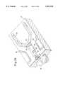
- FIG. 1is a perspective of an integrated micro-ceramic chemical plant in accordance with the present invention
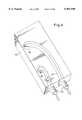
- FIG. 2is a perspective of the first layer of the integrated micro-ceramic chemical plant including the top portion showing the conduits for entry of the reactants to the plant;
- FIG. 3ais a perspective of the second layer from the top of the integrated micro-ceramic chemical plant showing the passages for chemical transport to the reaction chamber, heater arrangement;
- FIG. 3bis a partial magnified view of the second layer taken along the lines of A--A and B--B of FIG. 3a;
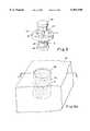
- FIG. 4is a perspective of the third layer of the integrated micro-ceramic chemical plant showing chambers for retrieving the reaction products and also an arrangement for discharging the reaction products out of the micro-ceramic chemical plant;
- FIG. 5is a perspective of a rotatable member that can have a plurality of micro-filters, micro-ceramic catalytic reaction chambers or a combination there of;
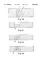
- FIG. 6ais a perspective of a micro-ceramic catalytic reaction chamber showing a typical arrangement of a spiral micro-channel;
- FIG. 6bis a cross-sectional view taken along lines A--A of FIG. 6a showing a micro-ceramic catalytic reaction chamber.
- FIG. 6cis a cross-sectional view taken along the line A--A of FIG. 5 showing a micro-filter
- FIG. 6dis a cross-sectional view taken along the line A--A of FIG. 5 showing a micro-ceramic catalytic reaction chamber
- FIG. 6eis a cross-sectional view taken along the line A--A of FIG. 5 showing a combination of micro-ceramic catalytic reaction chamber and micro-filter;
- FIG. 7is an exploded perspective of a micro-filter member and end caps
- FIG. 8is a perspective showing in more detail an end cap of FIG. 7;
- FIG. 9ais an exploded cross-sectional perspective showing in more detail a portion of the chemical plant and an end cap;
- FIG. 9bis another cross sectional perspective of the end cap taken along the lines A--A of FIG. 9a;
- FIG. 10is a perspective showing the rotatable member mounted to the integrated micro-ceramic chemical plant.
- the rate of a chemical reactioncan be increased by raising the temperature. However, this is not always feasible or practical. Some reactants and products decompose at high temperatures. From an economic standpoint, raising the temperature means increased energy costs. Fortunately, there are certain substances called catalysts that offer an alternative approach to speeding up a reaction. A catalyst increases the rate of reaction without being consumed by it. A catalyst operates by lowering activation energy for a chemical reaction.
- a heterogeneous catalystis one that is in a different phase from the reaction mixture. Most commonly, the catalyst will be a solid that increases the rate of a gas phase or fluid phase reaction.
- a homogeneous catalystis one that is present in the same phase as the reactants. It speeds up the reaction by forming a reactive intermediate that decomposes to give products. In this way, the catalyst provides an alternative path of lower activation energy for the reaction.
- a properly designed catalystshould have the essential attributes of activity, stability, selectivity, and regenerability. These can be related to the physical and chemical properties of the catalyst, which in turn can be related to the variable parameters inherent in the method used for the preparation of the catalyst. In addition to a wide range of techniques for the preparation of supported catalysts a substantial number of supports are available for such systems.
- the principal catalyst preparation techniqueinvolves two stages. First, laying a metal salt component into a finely divided form on a support, generally micro-porous ceramics and secondly, the conversion of the supported metal salt to a metallic or oxide state.
- the first stageis known as dispersion and is achieved by impregnation, adsorption from solution, co-precipitation, or deposition. While the second stage is called calcination or reduction.
- the primary aim of applying a catalytically active component to a supportis to obtain the catalyst in a highly dispersed form and hence, in a highly active form when expressed as a function of the weight of the active component.
- FIG. 1a perspective is illustrated of an integrated micromolded unitary ceramic block 10 including three different layers.
- Two separate rotatable members 14are shown to be partially insertable into receiving cavities formed in the second layer (see FIG. 3a).
- Each of these rotatable members 14include a micro-filter (see FIG. 6c), a micro-ceramic catalytic reaction chamber (see FIG. 6d) or a combination of a catalytic reaction chamber and micro-filter (see FIG. 6e). These arrangements will be subsequently discussed in detail. It will be understood that as many rotatable members as are needed can be used.
- FIG. 2shows the first ceramic layer 20 of the unitary ceramic block 10 which contains a row of chemical delivery inlet conduits 12 (which may be tubes) on one side. It is to be noted that the first ceramic layer 20 may include more than two conduits in a row. The conduits 12 lead directly to a second ceramic layer 30 through hole 13.
- FIG. 3ashows the second ceramic layer 30 which includes a chemical delivery chamber 34 and a chemical mixing chamber 35 in the form of micro-channels.
- One end of the chemical delivery chamber 34is located under the through hole 13 of the first ceramic layer 20. More than two micro-channels can of course be used in accordance with the present invention.
- the second ceramic layer 30has receiving chambers with holding tanks 36 and is formed with discharge holes 37 disposed in a chemical mixing chamber 35. It should be noted that when the rotatable member 14 includes only micro-filters then a catalytic reaction chamber 38 is formed in the second ceramic layer 30.
- rotatable member 14includes a permeable (semi-permeable) partition wall 39a which is made of a micro-porous and/or permeable ceramic material which permits the mixing of two different chemicals so that they can properly react as will be described later.
- the rotatable member 14includes only a micro-ceramic catalytic reaction chamber or a combination of a micro-ceramic catalytic reaction chamber and a micro-filter, the area labeled by 38 in FIGS. 3a and 3b designates a reaction chamber only.
- 6c-eis in direct communication either with reaction products or reaction fluids. More particularly, when the rotatable member 14 is inserted into the reaction chamber 38, one of a plurality of micro- filters 67 (See FIG. 6) separates the reaction products so as to retrieve desired reaction products. A motor 65 (See FIG. 5) rotates the rotatable member 14 to a position where one of the micro filters 67 is in communication with the reaction chamber 38 for separating the reaction products.
- the second ceramic layer 30also contains a catalytic reaction chamber 39 to facilitate catalytic reactions.
- the catalytic reaction chamber 39which is made from micro-porous ceramics impregnated with catalysts. This impregnation can be accomplished during manufacture of the catalytic reaction chamber 39 or during the final sintering step.
- the second ceramic layer 30contains embedded heating elements 40 surrounding the reaction chamber 38 and a thermocouple (not shown) inserted in feedthrough 42 (see FIG. 3a) which monitors and applies a signal to a control system (not shown) for monitoring and controlling the temperature in the reaction chamber 38.
- the permeable partition wall 39ais preferably made by dry pressing ceramic and its composite powders such as zirconia silicate, alumina silicate, zirconia, alumina, silicon carbide, silicon nitride and ceramic composites comprising zirconia-alumina at a pressure such that upon sintering the desired degree of porosity is maintained. It is very important that the pores need to be of the interconnecting variety.
- the permeable partition wall 39acan also be made alternatively by gel casting, tape casting and injection molding zirconia silicate or alumina silicate such that upon controlled sintering a varying degree of porosity is achieved.
- the permeable partition wall 39apermits controlled reaction between the chemicals in the fluids on either side of the permeable partition wall 39a to permit the mixing of such fluids during a reaction process.
- the ceramic powderis blended with polymeric fibers made of materials such as polyvinyl alcohol, polyethylene glycol or acrylic which upon sintering leaves behind interconnected micro-pores.
- the pore size or the diameter of the sacrificial organic fibersvary in a range from 0.1 to 10 ⁇ m because the degree of porosity (density) is warranted by the amount of permeability required for a given chemical process.
- custom tailored permeabilitycan be incorporated by controlling the compacting pressure, diameter of the polymer fibers and sintering temperature for a given ceramic composition.
- the preferred way of making the "green" permeable partition wall containing sacrificial organic fibers such as polyvinyl alcoholis to gel cast the ceramic mixture containing the organic binders and organic fibers in a mold and air drying the part to drive off the solvent. Upon compacting and subsequent firing the sacrificial organic fibers will produce a wall having a variable degree of porosity.
- the permeable partition wall 39awhich is in the "green” state, is then incorporated in the unitary ceramic "green” body before all the layers are assembled and sintered to form the sintered unitary micro-ceramic chemical plant.
- a plurality of channelscan be provided to handle more than two chemicals or alternatively the catalytic reaction chamber 38 can be made longer by configuring serpentine, complex, wavy, winding and angular meandering forms to allow for longer reaction time.
- An embedded ceramic heating element 40is provided in walls defining the perimeter of the chemical delivery chamber 34, the chemical mixing chamber 35, and the reaction/catalytic reaction chamber 38 to provide heat to these chambers. With certain chemical reactions it is particularly important to provide heat to the reaction/catalytic reaction chamber 38.
- the embedded heating element 40can be made from ceramics such as MoSi 2 , TiB 2 , ZrB 2 , WO 3 or high-temperature resistive metals or metallic alloys.
- the electrical leads 41see FIG.
- thermocouple 42located close to the heating element and a thermocouple (not shown) can be inserted in the feedthrough 42 for both monitor and control of temperature of the reaction chamber.
- the reaction/catalytic reaction chamber 38leads to discharge holes 37 contained in the chemical receiving chamber with holding tank 36 which merges into the next layer which is third ceramic layer 100.
- the cross-section of the catalytic reaction/reaction chamber 38is configured as a rectangle but can be of other shapes such as oval, circular, triangular or any other convenient cross-section.
- the discharge holes 37are directly connected to receiving chambers 60 in the third ceramic layer 100 (see FIG. 4).
- FIG. 4shows that the third ceramic layer 100 includes receiving chambers 60 disposed directly below the discharge holes 37 in the second ceramic layer 30.
- the receiving chambers 60receives liquid chemical reaction products and discharges these reaction products out of the integrated micro-ceramic chemical plant 10 through outlet tubes/conduits 62 via discharge channels 61.
- FIG. 5shows a perspective of the rotatable member 14 which can be used in accordance with the present invention.
- the rotatable member 14is formed with a plurality of cavities 63 and is fixedly secured to a shaft 64 which is rotated by a motor 65.
- Appropriate end caps with bearings 66are provided on opposite ends of the shaft 64.
- micro-pores in the filtersis of interconnecting type whereas in the catalytic reaction chambers the micro-pores are of non interconnecting type. Since the micro-pores of the catalytic reaction chambers are of non interconnecting type, micro-channels are incorporated in the micro-ceramic catalytic reaction chambers for passage of the reactants and the reaction products from the top surfaces to the bottom of the catalytic reaction chambers. A spiral arrangement micro-channel is considered to be most efficient in such a situation, because in such an arrangement of micro-channel, the largest area of catalytically active surface will be exposed to the chemical reactants for efficient catalyst assisted chemical reactions.
- FIG. 6ashows a perspective of a micro-ceramic catalytic reaction chamber 68 within a portion 70 of cavities of the rotatable member 63 indicating a typical arrangement of a spiral micro-channel 71 within a non-interconnecting micro-porous region 72 of the catalytic reaction chamber.
- FIG. 6bshows a cross-sectional view along lines A--A of micro-ceramic catalytic reaction chamber 68 of FIG. 6a depicting the spiral micro-channel 71 and the non-interconnecting micro-porous region 72.
- FIGS. 6c, 6d and 6eshow cross-sectional views along lines A--A of the rotatable member 14 of FIG. 5 showing the arrangements of a micro-filter 67, a micro-ceramic catalytic reaction chamber 68, and a micro-ceramic catalytic reaction chamber with micro-filter respectively.
- the rotatable member 14is designed in such a manner that either a micro-filter 67 or a micro-ceramic catalytic reaction chamber 68 or a combination of micro-ceramic catalytic reaction chamber and a micro-filter arrangement 69 can be positioned underneath the discharge hole 37 of the second ceramic layer 30.
- the embedded heating elements 40can be made from ceramic materials such as MoSi 2 , TiB 2 or ZrB 2 , WO 3 or high temperature metallic alloys such as Nichrome (Ni-Cr alloys used commercially as heating elements), and refractory metals such as Mo.
- the electrical leads 41 for the heating elements 40are located at the side of the ceramic plate and is an integral part of it.
- a feed-through 42which extends up to the wall of the chamber is provided which protrudes at an angle from outside to the surface of the second ceramic layer 30.
- a thermocouplecan be introduced through the feedthrough to measure as well as control the temperature. This thermocouple (not shown) is connected through a feed back control system to the heater power supply.
- FIG. 7an exploded perspective is shown of a rotatable member 14, and end caps with bearings 66.
- the rotatable member 14includes a rotatable disk 15 having disk surfaces 16 and 17, and shaft 64 with threaded grooves 88 and having ridges 90.
- Each end cap with bearing 66has a shaft receiving cavity 210 (see FIG. 8) and is pressed onto shaft 64 as will be described.
- FIG. 8is a perspective in more detail of one of the end caps with bearings 66.
- the end cap 66has a top portion 202, a shaft receiving cavity 210 which is formed by three flexible, spaced-apart support members 220 each of which has a lip portion 222, and a circular support wall 230 with a ridge portion 240.
- the end cap 66is mounted to shaft 64 of rotatable member 14 by inserting shaft 64 into the shaft receiving cavity 210.
- shaft 64As the shaft 64 initially enters the shaft receiving cavity 210 it forces apart support members 220 of end cap 66 when the lip portions 222 engage ridge 90 of shaft 64.
- the support members 220return to their unflexed positions with the lip portions 222 locked into the threaded groove 88 of shaft 64 thereby fixing the end cap 66 to the shaft 64.
- the end cap 66is removed from the shaft 64 by pulling it off thereby reversing the attachment process.
- FIG. 9aan exploded cross-sectional perspective is shown of a portion of integrated micro-ceramic chemical plant 280 and end cap 66.
- the portion of integrated micro-ceramic chemical plant 280comprises recesses 300, grooves 310 and a rotatable member receiving cavity 320.
- the rotatable member receiving cavity 320which has top and bottom surfaces 322 and side surfaces 324. These surfaces define the rotatable member receiving cavity 320 for receiving a portion of the rotatable disk 15 of rotatable member 14.
- FIG. 9ba cross-sectional perspective is shown of the end cap 66 mounted to the portion of integrated micro-ceramic chemical plant 280. Specifically, the end cap 66 is shown in a cross sectional view taken along line A--A in FIG. 9a. It is instructive to note that the end cap 66 is mounted to the portion of integrated micro-ceramic chemical plant 280 by inserting the circular support wall 230 of end cap 66 in circular groove 310 of the integrated micro-ceramic chemical plant 280.
- the rotatable member 14is mounted to a portion of integrated micro-ceramic chemical plant 280. Specifically, a portion of the rotatable disk 15 of rotatable member 14 (see FIG. 7) is inserted into the rotatable member receiving cavity 320 of the portion of integrated micro-ceramic chemical plant 280. Portions of the disk surfaces 16 and 17 are in contact with the surfaces 322 and 324, respectively of rotatable member receiving cavity 320 (see FIG. 9a). It should be noted that the disk surfaces 16 an 17 and the surfaces 322 and 324 of rotatable member receiving cavity 320 are smooth, nonporous, and wear and abrasion resistant.
- the surfaces in contact with one anothercan be slideably moved with respect to one another without causing degradation to either surface.
- the rotatable member receiving cavity 320is designed to provide a tight fit for the portion of the rotatable disk 15 inserted into it, so as to preclude fluid from the chemical plant from seeping between the disk surfaces 16 an 17 and the surfaces 322 and 324 of rotatable member receiving cavity 320, when they are in respective contact with one another.
- the shaft 64 of rotatable member 14is in contact with, and supported by recesses 300 in the portion of integrated micro-ceramic chemical plant 280.
- the end cap 66is pressed onto shaft 64 as described in the description of FIG. 8.
- the end cap 66is mounted to the portion of integrated micro-ceramic chemical plant 280 with its circular support wall 230 inserted into groove 310 as described in FIG. 9b.
- an additional end cap 66is pressed onto shaft 64 and concurrently mounted to the portion of chemical plant 280 by inserting its circular support wall 230 into groove 310. In this way the rotatable member 14 is fixedly attached to the portion of integrated micro-ceramic chemical plant 280.
- the present inventioninvolves an integrated micro-ceramic chemical plant.
- microrefers to the fact that the features within the chemical plant have dimensions of about 100 micrometers or less.
- the unitary ceramic block 10is formed by multiple ceramic layers in the "green” state which are sintered together. These layers can typically have dimensions 10 to 100 mm wide, 10 to 100 mm long, and 1 to 10 mm thick
- greenmeans that when particulate ceramic powder, preferably mixed with an organic binder is subjected to uniform compacting forces in order to provide an unsintered preform which has uniform density.
- One particular effective materialis a tetragonal zirconia ceramic powder that can be micromolded to form the layers by standard methods such as injection molding, gel casting, tape casting, dry pressing or cold isostatic pressing with "green” machining.
- Other ceramic materials which can be usedare Al 2 O 3 , AlN, BN, MgO, Al 2 O 3 --ZrO 2 composite, SiC, Si 3 N 4 and other oxide and non-oxide ceramics and their composites thereof.
- each layersuch as chambers, channels and passageways can be formed as follows:
- features like embedded coils and heating coilscan be formed by placing sacrificial members comprising organic polymers which are burned away during the sintering process.
- sacrificial memberscomprising organic polymers which are burned away during the sintering process.
- the details of forming embedded microfeaturesare described in the commonly assigned U.S. patent application Ser. No. 08/775,523, filed Jan. 2, 1997, entitled “Miniature Molded Ceramic Devices Having Embedded Spiral Coils” by Chatterjee et al, and commonly assigned U.S. patent application Ser. No. 08/775,524, filed Jan. 2, 1997, entitled “Method for Forming Molded Ceramic Devices Having Embedded Spiral Coils” by Chatterjee et al which are incorporated herein by reference.
- features like microchannelscan be formed by embedding organic sacrificial member which burn away during sintering or can be incorporated in the molding tools for pressure assisted replication on the "green" ceramic bodies.
- the "green” ceramic layersshrink due to the burning of the binders and also due to the consolidation of the ceramic and its composite powders. Provision must be made to compensate for this shrinkage by appropriately enlarging the features in the tools, such as dies and molds, used for replicating such features in the "green” parts.
- the rotatable member 14includes cavities 63. These cavities 63 can contain micro-filter, micro-ceramic catalytic reaction chamber, and micro-ceramic catalytic reaction chamber with micro-filter 67, 68 and 69. (See FIGS. 6c, 6d and 6e).
- the rotatable member 14 in the form of a diskcan be formed as follows:
- a) rotatable member shown as a disk 15 (FIG. 7) and the shaft 64 (FIG. 7) on which it is mountedcan be formed individually by cold pressing ceramic powders in a die and mold assembly forming "green" ceramic bodies and subsequently sintering those to a high temperature to form dense ceramic parts.
- the featuressuch as a central cavity for receiving the shaft and other cavities for incorporating micro-filter, micro-ceramic catalytic reaction chamber and the combination of micro-ceramic catalytic reaction chamber and micro-filter can be incorporated in the mold or die assembly.
- the mold or die assemblyreplicates those features in the "green” ceramic bodies.
- a fully dense, sintered shaft memberis subsequently shrink fitted or press fitted on to the central cavity of the rotatable disk 15.
- Alternative processes of manufacturingsuch as injection molding, cold isostatic pressing in conjunction with "green” machining, gel casting and subsequent sintering can also be adopted for forming the rotatable member.
- the rotatable disk 15 and its shaft 64can be made as a single unit.
- Well characterized fine ceramic or ceramic composite powder with appropriate amount of bindersis preferably used for consolidation in the above mentioned manufacturing processes.
- a preferred material and manufacturing process for forming the rotatable member assemblyis fully stabilized zirconia alloy powders and cold pressing of these powders with subsequent sintering of the cold pressed "green” ceramic bodies. This forming process produces a ⁇ net shape ⁇ rotatable member and the details of the manufacturing steps are described by Ghosh et al in commonly assigned U.S. Pat. No. 5,411,690, which is incorporated herein by reference.
- micro-filters 67which preferably are micro-porous ceramics are produced by mixing different sizes of polymeric fibers with the ceramic powders.
- An essential requirement of micro-filter materialsis that the pores should be of interconnecting variety.
- the fiberscan overlay on each other in a plurality of orientations.
- the ceramic powder/polymeric fiber mixis cold pressed in disk form corresponding to the shape of the cavities of the rotatable disk 15. These cold pressed disks can be subsequently sintered and the individual disks can be either press fitted or shrink fitted onto the individual cavities of the rotatable member.
- the ceramic powder/polymeric mixcan also be placed in the specific areas of the cavities of the rotatable member in the mold/die assembly in the manufacture of the rotatable member (see the process described in (a) above) and pressed before subsequent sintering.
- the polymeric fibersburn off, leaving porosities. Since the fibers overlap each other, the porosities thus created are interconnecting in nature.
- the pore densities and the sizes and shapes of the porescan be varied by appropriate choices of the amount and the type of polymeric fibers.
- the polymeric fibersinclude fibers made from polyvinyl alcohol, polyethylene glycol, acrylic, or from any organic compound which burns in air without leaving any residue.
- a wide range of fiber sizecan be chosen for forming the micro filters.
- the typical diametercan range from 0.1 to 15 ⁇ m and the length ranges from 1 to 25 ⁇ m. It should noted that the design should accommodate the approximately 20 to 50 percent larger sized features (such as size of the micro filter disks and also the size of the pores) depending on the ceramic material used, to account for shrinkage during sintering.
- the preferred materials for forming the micro filter disksare fully stabilized zirconia, zirconia-alumina composites, zirconia silicate, alumina silicate and other oxide and non-oxide ceramics and their composites.
- micro-ceramic catalytic reaction chamber 68is a micro-porous ceramics impregnated with catalysts.
- the porosity of these ceramicsare of the non-interconnecting variety.
- preparation of a properly designed micro-ceramic catalytic reaction chamberplays a very important role.
- the micro-pores in the catalytic reaction chamberaccept the catalysts and serve as housing for the catalysts.
- the micro-poreshave greater pore surface areas per unit volume of the pores and from geometrical considerations, if the pores are spherical in nature, large surface areas can be achieved.
- the micro-ceramic catalytic reaction chambercan be formed by thoroughly mixing ceramic or composite powders with finely dispersed spherical polymeric beads and cold pressing the mixture in a die/mold assembly before sintering at a high temperature.
- the pressure and temperature for cold pressing and sinteringcan vary depending on the ceramic material chosen for manufacture of micro-ceramic catalytic reaction chambers.
- the micro-pores of the catalytic reaction chambersare of non interconnecting type. Although the preferred nature of pores for use as support for various catalyst, this type of pores pose problems in the movement of both the reactants and the reaction products through the catalytic reaction chamber.
- micro-channelsare incorporated in the micro-ceramic catalytic reaction chambers for passage of the reactants and the reaction products from the top surfaces to the bottom of the catalytic reaction chambers.
- a spiral arrangement micro-channelis highly efficient in such situation, because in such an arrangement large areas of the catalytically active surface will be exposed to the chemical reactants for efficient catalyst assisted chemical reactions.
- a spiral micro-channel within the micro-ceramic catalytic reaction chambercan readily be formed by placing a sacrificial polymeric fiber formed in the form of a coil in a suitable location in the die/mold assembly.
- the die/mold assemblyis filled with a thoroughly mixed charge of ceramic or composite powder with finely dispersed spherical powder before cold pressing and sintering.
- More than one sacrificial polymeric fiber coilscan be used for forming multiple spiral channels within a micro-ceramic catalytic reaction chamber. Care should be taken in making sure that the terminal ends of each polymeric fiber coil terminates at the top and bottom surfaces of the "green" micro-ceramic catalytic reaction chamber. During the sintering process, the sacrificial polymeric fiber coil burn off leaving a spiral micro-channel.
- a preferred ceramic material for use in forming micro-ceramic catalytic reaction chambersis fully stabilized tetragonal zirconia alloy, although materials such as zirconia-alumina composites, zirconia silicate, alumina silicate and other oxide and non-oxide ceramics and their composites can be used to form such beds.
- micro-ceramic catalytic reaction chamberswith micro-channels.
- the micro-ceramic catalytic reaction chamberscan be formed separately and later can be incorporated in the micro-chemical plant by either press fitting or by shrink fitting. Alternatively, it can also be manufactured along with the rotatable member assembly.
- the catalyst preparation techniqueinvolves two stages.
- the dispersion of the metal saltis achieved by impregnation, adsorption from solution, co-precipitation, or deposition, while the conversion of the metal salt to a metallic or oxide state is achieved either by calcination or by reduction.
- All the techniques of catalyst preparationreduce to two simple steps: dispersing the active material in a fluid or gaseous form and immobilizing this dispersed material as it is reconverted to an insoluble solid form.
- the primary aim of applying a catalytically active component to a micro-porous micro-ceramic catalytic reaction chamberis to obtain the catalyst in a highly dispersed form.
- a properly designed catalystshould have the essential attributes of activity, stability, selectivity, and regenerability. These can be related to the physical and chemical properties of the catalyst, which in turn can be related to the variable parameters inherent in the method used for the preparation of the catalyst.
- micro-ceramic catalytic reaction chamber and the micro-filter combination 69 of this inventioncan be formed separately by the processes described above and either shrink or press fitted onto the cavities of the rotatable member 63.
- the porosities in the micro-ceramic unitary membercan be varied in a functionally gradient manner in such a fashion that the top portion of the unitary micro-ceramic member contain predominantly non-interconnecting porosity, whereas the bottom portion of the member contain predominantly interconnecting porosity.
- the top portionalso contain spiral micro-channels as described earlier is impregnated with catalysts.
- micro-ceramic catalytic reaction chamber with micro-filter69 micro-ceramic catalytic reaction chamber with micro-filter
Landscapes
- Chemical & Material Sciences (AREA)
- Organic Chemistry (AREA)
- Chemical Kinetics & Catalysis (AREA)
- Physical Or Chemical Processes And Apparatus (AREA)
- Catalysts (AREA)
Abstract
Description
Claims (8)
Priority Applications (1)
| Application Number | Priority Date | Filing Date | Title |
|---|---|---|---|
| US08/951,179US5961930A (en) | 1997-10-15 | 1997-10-15 | Integrated micro-ceramic chemical plant with insertable reaction chambers and micro-filters |
Applications Claiming Priority (1)
| Application Number | Priority Date | Filing Date | Title |
|---|---|---|---|
| US08/951,179US5961930A (en) | 1997-10-15 | 1997-10-15 | Integrated micro-ceramic chemical plant with insertable reaction chambers and micro-filters |
Publications (1)
| Publication Number | Publication Date |
|---|---|
| US5961930Atrue US5961930A (en) | 1999-10-05 |
Family
ID=25491376
Family Applications (1)
| Application Number | Title | Priority Date | Filing Date |
|---|---|---|---|
| US08/951,179Expired - LifetimeUS5961930A (en) | 1997-10-15 | 1997-10-15 | Integrated micro-ceramic chemical plant with insertable reaction chambers and micro-filters |
Country Status (1)
| Country | Link |
|---|---|
| US (1) | US5961930A (en) |
Cited By (31)
| Publication number | Priority date | Publication date | Assignee | Title |
|---|---|---|---|---|
| EP1224976A1 (en)* | 2000-12-28 | 2002-07-24 | F. Hoffmann-La Roche Ag | Method, system and cartridge for processing a nucleic acid sample by oscillating the cartridge |
| US20030027022A1 (en)* | 2001-08-06 | 2003-02-06 | Arana Leonel R. | Thermally effcient micromachined device |
| US6527890B1 (en) | 1998-10-09 | 2003-03-04 | Motorola, Inc. | Multilayered ceramic micro-gas chromatograph and method for making the same |
| US20030100792A1 (en)* | 2001-08-21 | 2003-05-29 | Clariant Gmbh | Process for preparing arylboron and alkylboron compounds in microreactors |
| US20030103878A1 (en)* | 2001-12-05 | 2003-06-05 | The Regents Of The University Of California | Chemical microreactor and method thereof |
| US6592696B1 (en) | 1998-10-09 | 2003-07-15 | Motorola, Inc. | Method for fabricating a multilayered structure and the structures formed by the method |
| US20030194362A1 (en)* | 2002-04-12 | 2003-10-16 | Rogers Stephen P. | Chemical reactor and fuel processor utilizing ceramic technology |
| US20030210607A1 (en)* | 2002-05-08 | 2003-11-13 | Coventor, Inc. | On chip dilution system |
| US20040081589A1 (en)* | 2002-08-29 | 2004-04-29 | Alexanian Ara J. | Elevated temperature combinatorial catalytic reactor |
| US20040129371A1 (en)* | 2003-01-07 | 2004-07-08 | International Business Machines Corporation | Multichannel and multilayer pharmaceutical device |
| US20050008909A1 (en)* | 2003-06-27 | 2005-01-13 | Ultracell Corporation | Efficient micro fuel cell systems and methods |
| US20050005521A1 (en)* | 2003-06-27 | 2005-01-13 | Ultracell Corporation | Fuel processor dewar and methods |
| US20050014059A1 (en)* | 2003-06-27 | 2005-01-20 | Ultracell Corporation | Micro fuel cell architecture |
| US20050069462A1 (en)* | 2003-09-30 | 2005-03-31 | International Business Machines Corporation | Microfluidics Packaging |
| US20050069949A1 (en)* | 2003-09-30 | 2005-03-31 | International Business Machines Corporation | Microfabricated Fluidic Structures |
| US20050077657A1 (en)* | 2003-10-14 | 2005-04-14 | International Business Machines Corporation | A Method of Making a Multichannel and Multilayer Pharmaceutical Device |
| US20050112621A1 (en)* | 2003-11-25 | 2005-05-26 | Korea Institute Of Science And Technology | Quantitative biopolymer detecting system using monolithic piezoelectric cantilever by resonant frequency shift, method for fabricating the same system and method for detecting biopolymer quantitatively using the same system |
| US20050129580A1 (en)* | 2003-02-26 | 2005-06-16 | Swinehart Philip R. | Microfluidic chemical reactor for the manufacture of chemically-produced nanoparticles |
| US6932951B1 (en) | 1999-10-29 | 2005-08-23 | Massachusetts Institute Of Technology | Microfabricated chemical reactor |
| US20060029848A1 (en)* | 2004-08-06 | 2006-02-09 | Ultracell Corporation | Method and system for controlling fluid delivery in a fuel cell |
| US20060039831A1 (en)* | 2004-08-20 | 2006-02-23 | International Business Machines Corporation | Optical micro plugs for multichannel and multilayer pharmaceutical device |
| US20060071009A1 (en)* | 2003-06-27 | 2006-04-06 | Ultracell Corporation | Fuel cell cartridge with leak detection |
| US20060127719A1 (en)* | 2003-06-27 | 2006-06-15 | Ultracell Corporation, A California Corporation | Heat efficient portable fuel cell systems |
| US20060134470A1 (en)* | 2004-12-21 | 2006-06-22 | Ultracell Corporation | Compact fuel cell package |
| US20060156627A1 (en)* | 2003-06-27 | 2006-07-20 | Ultracell Corporation | Fuel processor for use with portable fuel cells |
| US20060194082A1 (en)* | 2005-02-02 | 2006-08-31 | Ultracell Corporation | Systems and methods for protecting a fuel cell |
| US20080057360A1 (en)* | 2003-06-27 | 2008-03-06 | Ultracell Corporation | Portable systems for engine block |
| US7648792B2 (en) | 2004-06-25 | 2010-01-19 | Ultracell Corporation | Disposable component on a fuel cartridge and for use with a portable fuel cell system |
| US7968250B2 (en) | 2004-06-25 | 2011-06-28 | Ultracell Corporation | Fuel cartridge connectivity |
| US8821832B2 (en) | 2003-06-27 | 2014-09-02 | UltraCell, L.L.C. | Fuel processor for use with portable fuel cells |
| CN115015567A (en)* | 2022-08-05 | 2022-09-06 | 南京纳摩尔仪器有限公司 | Ceramic 3D tunnel type analysis module |
Citations (5)
| Publication number | Priority date | Publication date | Assignee | Title |
|---|---|---|---|---|
| US5480614A (en)* | 1993-03-16 | 1996-01-02 | Hitachi, Ltd. | Micro-reactor device for minute sample analysis |
| US5534328A (en)* | 1993-12-02 | 1996-07-09 | E. I. Du Pont De Nemours And Company | Integrated chemical processing apparatus and processes for the preparation thereof |
| US5658537A (en)* | 1995-07-18 | 1997-08-19 | Basf Corporation | Plate-type chemical reactor |
| US5863502A (en)* | 1996-01-24 | 1999-01-26 | Sarnoff Corporation | Parallel reaction cassette and associated devices |
| US5869004A (en)* | 1997-06-09 | 1999-02-09 | Caliper Technologies Corp. | Methods and apparatus for in situ concentration and/or dilution of materials in microfluidic systems |
- 1997
- 1997-10-15USUS08/951,179patent/US5961930A/ennot_activeExpired - Lifetime
Patent Citations (5)
| Publication number | Priority date | Publication date | Assignee | Title |
|---|---|---|---|---|
| US5480614A (en)* | 1993-03-16 | 1996-01-02 | Hitachi, Ltd. | Micro-reactor device for minute sample analysis |
| US5534328A (en)* | 1993-12-02 | 1996-07-09 | E. I. Du Pont De Nemours And Company | Integrated chemical processing apparatus and processes for the preparation thereof |
| US5658537A (en)* | 1995-07-18 | 1997-08-19 | Basf Corporation | Plate-type chemical reactor |
| US5863502A (en)* | 1996-01-24 | 1999-01-26 | Sarnoff Corporation | Parallel reaction cassette and associated devices |
| US5869004A (en)* | 1997-06-09 | 1999-02-09 | Caliper Technologies Corp. | Methods and apparatus for in situ concentration and/or dilution of materials in microfluidic systems |
Cited By (83)
| Publication number | Priority date | Publication date | Assignee | Title |
|---|---|---|---|---|
| US6592696B1 (en) | 1998-10-09 | 2003-07-15 | Motorola, Inc. | Method for fabricating a multilayered structure and the structures formed by the method |
| US6572830B1 (en)* | 1998-10-09 | 2003-06-03 | Motorola, Inc. | Integrated multilayered microfludic devices and methods for making the same |
| US6732567B2 (en) | 1998-10-09 | 2004-05-11 | Motorola, Inc. | Multilayered ceramic micro-gas chromatograph and method for making the same |
| US6527890B1 (en) | 1998-10-09 | 2003-03-04 | Motorola, Inc. | Multilayered ceramic micro-gas chromatograph and method for making the same |
| US6544734B1 (en) | 1998-10-09 | 2003-04-08 | Cynthia G. Briscoe | Multilayered microfluidic DNA analysis system and method |
| US6932951B1 (en) | 1999-10-29 | 2005-08-23 | Massachusetts Institute Of Technology | Microfabricated chemical reactor |
| US20050170496A1 (en)* | 2000-12-28 | 2005-08-04 | Roche Molecular Systems, Inc. | Method for processing a nucleic acid sample by oscillating a cartridge, a system and a cartridge for performing such a method |
| US20020155475A1 (en)* | 2000-12-28 | 2002-10-24 | Peter Vischer | Method for processing a nucleic acid sample by oscillating a cartridge, a system and a cartridge for performing such a method |
| EP1224976A1 (en)* | 2000-12-28 | 2002-07-24 | F. Hoffmann-La Roche Ag | Method, system and cartridge for processing a nucleic acid sample by oscillating the cartridge |
| US6921639B2 (en) | 2000-12-28 | 2005-07-26 | Roche Molecular Systems, Inc. | Method for processing a nucleic acid sample by oscillating a cartridge, a system and a cartridge for performing such a method |
| US7435575B2 (en) | 2000-12-28 | 2008-10-14 | Roche Molecular Systems, Inc. | Method for processing a nucleic acid sample by oscillating a cartridge, a system and a cartridge for performing such a method |
| US6939632B2 (en) | 2001-08-06 | 2005-09-06 | Massachusetts Institute Of Technology | Thermally efficient micromachined device |
| US20060283584A1 (en)* | 2001-08-06 | 2006-12-21 | Massachusetts Institute Of Technology | Thermally efficient micromachined device |
| US20030027022A1 (en)* | 2001-08-06 | 2003-02-06 | Arana Leonel R. | Thermally effcient micromachined device |
| US7267779B2 (en) | 2001-08-06 | 2007-09-11 | Massachusetts Institute Of Technology | Thermally efficient micromachined device |
| US20030100792A1 (en)* | 2001-08-21 | 2003-05-29 | Clariant Gmbh | Process for preparing arylboron and alkylboron compounds in microreactors |
| US20030103878A1 (en)* | 2001-12-05 | 2003-06-05 | The Regents Of The University Of California | Chemical microreactor and method thereof |
| US7993534B2 (en)* | 2001-12-05 | 2011-08-09 | Lawrence Livermore National Security, Llc | Chemical microreactor and method thereof |
| US6960235B2 (en)* | 2001-12-05 | 2005-11-01 | The Regents Of The University Of California | Chemical microreactor and method thereof |
| US20090223925A1 (en)* | 2001-12-05 | 2009-09-10 | Morse Jeffrey D | Chemical microreactor and method thereof |
| US20030194362A1 (en)* | 2002-04-12 | 2003-10-16 | Rogers Stephen P. | Chemical reactor and fuel processor utilizing ceramic technology |
| WO2003086613A1 (en)* | 2002-04-12 | 2003-10-23 | Motorola, Inc., A Corporation Of The State Of Delaware | Chemical reactor and fuel processor utilizing ceramic technology |
| US20050148082A1 (en)* | 2002-05-08 | 2005-07-07 | Cytonome, Inc. | On chip dilution system |
| US7401972B2 (en) | 2002-05-08 | 2008-07-22 | Cytonome, Inc. | On chip dilution system |
| US6883957B2 (en) | 2002-05-08 | 2005-04-26 | Cytonome, Inc. | On chip dilution system |
| US20030210607A1 (en)* | 2002-05-08 | 2003-11-13 | Coventor, Inc. | On chip dilution system |
| US20040081589A1 (en)* | 2002-08-29 | 2004-04-29 | Alexanian Ara J. | Elevated temperature combinatorial catalytic reactor |
| US6955777B2 (en) | 2003-01-07 | 2005-10-18 | International Business Machines Corporation | Method of forming a plate for dispensing chemicals |
| US20040129371A1 (en)* | 2003-01-07 | 2004-07-08 | International Business Machines Corporation | Multichannel and multilayer pharmaceutical device |
| US20050129580A1 (en)* | 2003-02-26 | 2005-06-16 | Swinehart Philip R. | Microfluidic chemical reactor for the manufacture of chemically-produced nanoparticles |
| US20090123797A1 (en)* | 2003-06-27 | 2009-05-14 | Ultracell Corporation | Efficient micro fuel cell systems and methods |
| US20050011125A1 (en)* | 2003-06-27 | 2005-01-20 | Ultracell Corporation, A California Corporation | Annular fuel processor and methods |
| US8821832B2 (en) | 2003-06-27 | 2014-09-02 | UltraCell, L.L.C. | Fuel processor for use with portable fuel cells |
| US8318368B2 (en) | 2003-06-27 | 2012-11-27 | UltraCell, L.L.C. | Portable systems for engine block |
| US8043757B2 (en) | 2003-06-27 | 2011-10-25 | UltraCell Acquisition Company, L.L.C. | Efficient micro fuel cell systems and methods |
| US20050008909A1 (en)* | 2003-06-27 | 2005-01-13 | Ultracell Corporation | Efficient micro fuel cell systems and methods |
| US7943263B2 (en) | 2003-06-27 | 2011-05-17 | Ultracell Corporation | Heat efficient portable fuel cell systems |
| US20060071009A1 (en)* | 2003-06-27 | 2006-04-06 | Ultracell Corporation | Fuel cell cartridge with leak detection |
| US20060127719A1 (en)* | 2003-06-27 | 2006-06-15 | Ultracell Corporation, A California Corporation | Heat efficient portable fuel cell systems |
| US7935452B2 (en) | 2003-06-27 | 2011-05-03 | Ultracell Corporation | Micro fuel cell architecture |
| US20060156627A1 (en)* | 2003-06-27 | 2006-07-20 | Ultracell Corporation | Fuel processor for use with portable fuel cells |
| US7807130B2 (en) | 2003-06-27 | 2010-10-05 | Ultracell Corporation | Fuel processor dewar and methods |
| US7807129B2 (en) | 2003-06-27 | 2010-10-05 | Ultracell Corporation | Portable fuel processor |
| US7763368B2 (en) | 2003-06-27 | 2010-07-27 | Ultracell Corporation | Efficient micro fuel cell systems and methods |
| US20050022448A1 (en)* | 2003-06-27 | 2005-02-03 | Ultracell Corporation | Planar micro fuel processor |
| US7276096B2 (en) | 2003-06-27 | 2007-10-02 | Ultracell Corporation | Fuel processor dewar and methods |
| US7291191B2 (en) | 2003-06-27 | 2007-11-06 | Ultracell Corporation | Fuel cell cartridge filters and pressure relief |
| US20070269703A1 (en)* | 2003-06-27 | 2007-11-22 | Ultracell Corporation | Micro fuel cell architecture |
| US20070292729A1 (en)* | 2003-06-27 | 2007-12-20 | Ultracell Corporation | Heat efficient portable fuel cell systems |
| US20070294941A1 (en)* | 2003-06-27 | 2007-12-27 | Ultracell Corporation | Fuel processor dewar and methods |
| US20080008646A1 (en)* | 2003-06-27 | 2008-01-10 | Ultracell Corporation | Portable fuel processor |
| US20080016767A1 (en)* | 2003-06-27 | 2008-01-24 | Ultracell Corporation | Fuel processor for use with portable fuel cells |
| US20080038601A1 (en)* | 2003-06-27 | 2008-02-14 | Ultracell Corporation | Efficient micro fuel cell systems and methods |
| US20080057360A1 (en)* | 2003-06-27 | 2008-03-06 | Ultracell Corporation | Portable systems for engine block |
| US7666539B2 (en) | 2003-06-27 | 2010-02-23 | Ultracell Corporation | Heat efficient portable fuel cell systems |
| US7401712B2 (en) | 2003-06-27 | 2008-07-22 | Ultracell Corporation | Smart fuel cell cartridge |
| US20050014059A1 (en)* | 2003-06-27 | 2005-01-20 | Ultracell Corporation | Micro fuel cell architecture |
| US20050186455A1 (en)* | 2003-06-27 | 2005-08-25 | Ultracell Corporation, A California Corporation | Micro fuel cell system start up and shut down systems and methods |
| US7462208B2 (en) | 2003-06-27 | 2008-12-09 | Ultracell Corporation | Planar micro fuel processor |
| US20090071072A1 (en)* | 2003-06-27 | 2009-03-19 | Ultracell Corporation | Planar micro fuel processor |
| US20050014040A1 (en)* | 2003-06-27 | 2005-01-20 | Ultracell Corporation | Fuel preheat in fuel cells and portable electronics |
| US7585581B2 (en) | 2003-06-27 | 2009-09-08 | Ultracell Corporation | Micro fuel cell architecture |
| US20050005521A1 (en)* | 2003-06-27 | 2005-01-13 | Ultracell Corporation | Fuel processor dewar and methods |
| US7604673B2 (en) | 2003-06-27 | 2009-10-20 | Ultracell Corporation | Annular fuel processor and methods |
| US7622207B2 (en) | 2003-06-27 | 2009-11-24 | Ultracell Corporation | Fuel cell cartridge with reformate filtering |
| US7655337B2 (en) | 2003-06-27 | 2010-02-02 | Ultracell Corporation | Micro fuel cell thermal management |
| US20050069949A1 (en)* | 2003-09-30 | 2005-03-31 | International Business Machines Corporation | Microfabricated Fluidic Structures |
| US20050069462A1 (en)* | 2003-09-30 | 2005-03-31 | International Business Machines Corporation | Microfluidics Packaging |
| US20050077657A1 (en)* | 2003-10-14 | 2005-04-14 | International Business Machines Corporation | A Method of Making a Multichannel and Multilayer Pharmaceutical Device |
| US20050112621A1 (en)* | 2003-11-25 | 2005-05-26 | Korea Institute Of Science And Technology | Quantitative biopolymer detecting system using monolithic piezoelectric cantilever by resonant frequency shift, method for fabricating the same system and method for detecting biopolymer quantitatively using the same system |
| US7648792B2 (en) | 2004-06-25 | 2010-01-19 | Ultracell Corporation | Disposable component on a fuel cartridge and for use with a portable fuel cell system |
| US7968250B2 (en) | 2004-06-25 | 2011-06-28 | Ultracell Corporation | Fuel cartridge connectivity |
| US7892690B2 (en) | 2004-08-06 | 2011-02-22 | Ultracell Corporation | Methods for controlling fluid delivery in a micro fuel cell system |
| US20060029848A1 (en)* | 2004-08-06 | 2006-02-09 | Ultracell Corporation | Method and system for controlling fluid delivery in a fuel cell |
| US7205060B2 (en) | 2004-08-06 | 2007-04-17 | Ultracell Corporation | Method and system for controlling fluid delivery in a fuel cell |
| US20060039831A1 (en)* | 2004-08-20 | 2006-02-23 | International Business Machines Corporation | Optical micro plugs for multichannel and multilayer pharmaceutical device |
| US7645423B2 (en) | 2004-08-20 | 2010-01-12 | International Business Machines Corporation | Optical micro plugs for multichannel and multilayer pharmaceutical device |
| US20110020717A1 (en)* | 2004-12-21 | 2011-01-27 | Ultracell Corporation | Compact fuel cell package |
| US20060134470A1 (en)* | 2004-12-21 | 2006-06-22 | Ultracell Corporation | Compact fuel cell package |
| US7807313B2 (en) | 2004-12-21 | 2010-10-05 | Ultracell Corporation | Compact fuel cell package |
| US20060194082A1 (en)* | 2005-02-02 | 2006-08-31 | Ultracell Corporation | Systems and methods for protecting a fuel cell |
| US20080171239A1 (en)* | 2005-02-02 | 2008-07-17 | Ultracell Corporation | Systems and methods for protecting a fuel cell |
| CN115015567A (en)* | 2022-08-05 | 2022-09-06 | 南京纳摩尔仪器有限公司 | Ceramic 3D tunnel type analysis module |
Similar Documents
| Publication | Publication Date | Title |
|---|---|---|
| US5961930A (en) | Integrated micro-ceramic chemical plant with insertable reaction chambers and micro-filters | |
| US5976472A (en) | Integrated micro-ceramic chemical plant with insertable catalytic reaction chambers | |
| US6036927A (en) | Micro-ceramic chemical plant having catalytic reaction chamber | |
| US5965092A (en) | Integrated micro-ceramic chemical plant with insertable micro-filters | |
| US5961932A (en) | Reaction chamber for an integrated micro-ceramic chemical plant | |
| US5993750A (en) | Integrated ceramic micro-chemical plant | |
| Knitter et al. | Microfabrication of ceramic microreactors | |
| EP1440308B1 (en) | A microfluidic device and manufacture thereof | |
| CN100460054C (en) | Porous film microstructure device and its manufacturing method | |
| US8206025B2 (en) | Microfluid mixer, methods of use and methods of manufacture thereof | |
| ES2305482T3 (en) | ALUMINA FILTER AGLOMERATED BY REACTION AND MEMBRANE SUPPORT. | |
| US20050170142A1 (en) | Coated microstructures and methods of coating same | |
| US20240165848A1 (en) | Pressed ceramic fluidic module with porous and non-porous structures | |
| WO2021067459A1 (en) | Fabrication of flow reactor modules and modules produced | |
| US6596168B2 (en) | Filter element and method for the manufacture | |
| HUT63132A (en) | Process for producing self-carrying ceramic product of composite structure and self-carrying ceramic body of composite structure | |
| JP2022530666A (en) | Monolithic ceramic body and assembly | |
| EP4171797A1 (en) | Pressed silicon carbide ceramic (sic) fluidic modules with integrated heat exchange | |
| CN116568470A (en) | Process for compacting ceramic bodies with internal channels or cavities formed by powder surrounding an internal mold | |
| JP2022119539A (en) | heat exchanger and reformer | |
| US20240157600A1 (en) | Pre-pressed ceramic bodies for fabrication of fluid devices and fluid devices produced | |
| JP7210365B2 (en) | Vaporizer and fluid supply device including the same | |
| WO2010096841A1 (en) | Packing material | |
| WO2022204019A1 (en) | Fabrication of fluid devices and fluid devices produced | |
| JP2003170411A (en) | Ceramics green body and method for producing the same |
Legal Events
| Date | Code | Title | Description |
|---|---|---|---|
| AS | Assignment | Owner name:EASTMAN KODAK COMPANY, NEW YORK Free format text:ASSIGNMENT OF ASSIGNORS INTEREST;ASSIGNORS:CHATTERJEE, DILIP K.;GHOSH, SYAMAL K.;FURLANI, EDWARD P.;REEL/FRAME:008779/0571;SIGNING DATES FROM 19971010 TO 19971013 | |
| STCF | Information on status: patent grant | Free format text:PATENTED CASE | |
| FEPP | Fee payment procedure | Free format text:PAYOR NUMBER ASSIGNED (ORIGINAL EVENT CODE: ASPN); ENTITY STATUS OF PATENT OWNER: LARGE ENTITY | |
| FPAY | Fee payment | Year of fee payment:4 | |
| FPAY | Fee payment | Year of fee payment:8 | |
| FPAY | Fee payment | Year of fee payment:12 | |
| AS | Assignment | Owner name:CITICORP NORTH AMERICA, INC., AS AGENT, NEW YORK Free format text:SECURITY INTEREST;ASSIGNORS:EASTMAN KODAK COMPANY;PAKON, INC.;REEL/FRAME:028201/0420 Effective date:20120215 | |
| AS | Assignment | Owner name:WILMINGTON TRUST, NATIONAL ASSOCIATION, AS AGENT, Free format text:PATENT SECURITY AGREEMENT;ASSIGNORS:EASTMAN KODAK COMPANY;PAKON, INC.;REEL/FRAME:030122/0235 Effective date:20130322 Owner name:WILMINGTON TRUST, NATIONAL ASSOCIATION, AS AGENT, MINNESOTA Free format text:PATENT SECURITY AGREEMENT;ASSIGNORS:EASTMAN KODAK COMPANY;PAKON, INC.;REEL/FRAME:030122/0235 Effective date:20130322 | |
| AS | Assignment | Owner name:BARCLAYS BANK PLC, AS ADMINISTRATIVE AGENT, NEW YORK Free format text:INTELLECTUAL PROPERTY SECURITY AGREEMENT (SECOND LIEN);ASSIGNORS:EASTMAN KODAK COMPANY;FAR EAST DEVELOPMENT LTD.;FPC INC.;AND OTHERS;REEL/FRAME:031159/0001 Effective date:20130903 Owner name:JPMORGAN CHASE BANK, N.A., AS ADMINISTRATIVE, DELAWARE Free format text:INTELLECTUAL PROPERTY SECURITY AGREEMENT (FIRST LIEN);ASSIGNORS:EASTMAN KODAK COMPANY;FAR EAST DEVELOPMENT LTD.;FPC INC.;AND OTHERS;REEL/FRAME:031158/0001 Effective date:20130903 Owner name:JPMORGAN CHASE BANK, N.A., AS ADMINISTRATIVE, DELA Free format text:INTELLECTUAL PROPERTY SECURITY AGREEMENT (FIRST LIEN);ASSIGNORS:EASTMAN KODAK COMPANY;FAR EAST DEVELOPMENT LTD.;FPC INC.;AND OTHERS;REEL/FRAME:031158/0001 Effective date:20130903 Owner name:BARCLAYS BANK PLC, AS ADMINISTRATIVE AGENT, NEW YO Free format text:INTELLECTUAL PROPERTY SECURITY AGREEMENT (SECOND LIEN);ASSIGNORS:EASTMAN KODAK COMPANY;FAR EAST DEVELOPMENT LTD.;FPC INC.;AND OTHERS;REEL/FRAME:031159/0001 Effective date:20130903 Owner name:PAKON, INC., NEW YORK Free format text:RELEASE OF SECURITY INTEREST IN PATENTS;ASSIGNORS:CITICORP NORTH AMERICA, INC., AS SENIOR DIP AGENT;WILMINGTON TRUST, NATIONAL ASSOCIATION, AS JUNIOR DIP AGENT;REEL/FRAME:031157/0451 Effective date:20130903 Owner name:EASTMAN KODAK COMPANY, NEW YORK Free format text:RELEASE OF SECURITY INTEREST IN PATENTS;ASSIGNORS:CITICORP NORTH AMERICA, INC., AS SENIOR DIP AGENT;WILMINGTON TRUST, NATIONAL ASSOCIATION, AS JUNIOR DIP AGENT;REEL/FRAME:031157/0451 Effective date:20130903 Owner name:BANK OF AMERICA N.A., AS AGENT, MASSACHUSETTS Free format text:INTELLECTUAL PROPERTY SECURITY AGREEMENT (ABL);ASSIGNORS:EASTMAN KODAK COMPANY;FAR EAST DEVELOPMENT LTD.;FPC INC.;AND OTHERS;REEL/FRAME:031162/0117 Effective date:20130903 | |
| AS | Assignment | Owner name:EASTMAN KODAK COMPANY, NEW YORK Free format text:RELEASE BY SECURED PARTY;ASSIGNOR:BARCLAYS BANK PLC;REEL/FRAME:041656/0531 Effective date:20170202 | |
| AS | Assignment | Owner name:CREO MANUFACTURING AMERICA LLC, NEW YORK Free format text:RELEASE BY SECURED PARTY;ASSIGNOR:JP MORGAN CHASE BANK, N.A., AS ADMINISTRATIVE AGENT;REEL/FRAME:049814/0001 Effective date:20190617 Owner name:QUALEX, INC., NEW YORK Free format text:RELEASE BY SECURED PARTY;ASSIGNOR:JP MORGAN CHASE BANK, N.A., AS ADMINISTRATIVE AGENT;REEL/FRAME:049814/0001 Effective date:20190617 Owner name:PAKON, INC., NEW YORK Free format text:RELEASE BY SECURED PARTY;ASSIGNOR:JP MORGAN CHASE BANK, N.A., AS ADMINISTRATIVE AGENT;REEL/FRAME:049814/0001 Effective date:20190617 Owner name:KODAK AVIATION LEASING LLC, NEW YORK Free format text:RELEASE BY SECURED PARTY;ASSIGNOR:JP MORGAN CHASE BANK, N.A., AS ADMINISTRATIVE AGENT;REEL/FRAME:049814/0001 Effective date:20190617 Owner name:FAR EAST DEVELOPMENT LTD., NEW YORK Free format text:RELEASE BY SECURED PARTY;ASSIGNOR:JP MORGAN CHASE BANK, N.A., AS ADMINISTRATIVE AGENT;REEL/FRAME:049814/0001 Effective date:20190617 Owner name:KODAK REALTY, INC., NEW YORK Free format text:RELEASE BY SECURED PARTY;ASSIGNOR:JP MORGAN CHASE BANK, N.A., AS ADMINISTRATIVE AGENT;REEL/FRAME:049814/0001 Effective date:20190617 Owner name:LASER PACIFIC MEDIA CORPORATION, NEW YORK Free format text:RELEASE BY SECURED PARTY;ASSIGNOR:JP MORGAN CHASE BANK, N.A., AS ADMINISTRATIVE AGENT;REEL/FRAME:049814/0001 Effective date:20190617 Owner name:KODAK PORTUGUESA LIMITED, NEW YORK Free format text:RELEASE BY SECURED PARTY;ASSIGNOR:JP MORGAN CHASE BANK, N.A., AS ADMINISTRATIVE AGENT;REEL/FRAME:049814/0001 Effective date:20190617 Owner name:KODAK PHILIPPINES, LTD., NEW YORK Free format text:RELEASE BY SECURED PARTY;ASSIGNOR:JP MORGAN CHASE BANK, N.A., AS ADMINISTRATIVE AGENT;REEL/FRAME:049814/0001 Effective date:20190617 Owner name:NPEC, INC., NEW YORK Free format text:RELEASE BY SECURED PARTY;ASSIGNOR:JP MORGAN CHASE BANK, N.A., AS ADMINISTRATIVE AGENT;REEL/FRAME:049814/0001 Effective date:20190617 Owner name:KODAK (NEAR EAST), INC., NEW YORK Free format text:RELEASE BY SECURED PARTY;ASSIGNOR:JP MORGAN CHASE BANK, N.A., AS ADMINISTRATIVE AGENT;REEL/FRAME:049814/0001 Effective date:20190617 Owner name:EASTMAN KODAK COMPANY, NEW YORK Free format text:RELEASE BY SECURED PARTY;ASSIGNOR:JP MORGAN CHASE BANK, N.A., AS ADMINISTRATIVE AGENT;REEL/FRAME:049814/0001 Effective date:20190617 Owner name:FPC, INC., NEW YORK Free format text:RELEASE BY SECURED PARTY;ASSIGNOR:JP MORGAN CHASE BANK, N.A., AS ADMINISTRATIVE AGENT;REEL/FRAME:049814/0001 Effective date:20190617 Owner name:KODAK AMERICAS, LTD., NEW YORK Free format text:RELEASE BY SECURED PARTY;ASSIGNOR:JP MORGAN CHASE BANK, N.A., AS ADMINISTRATIVE AGENT;REEL/FRAME:049814/0001 Effective date:20190617 Owner name:KODAK IMAGING NETWORK, INC., NEW YORK Free format text:RELEASE BY SECURED PARTY;ASSIGNOR:JP MORGAN CHASE BANK, N.A., AS ADMINISTRATIVE AGENT;REEL/FRAME:049814/0001 Effective date:20190617 | |
| AS | Assignment | Owner name:EASTMAN KODAK COMPANY, NEW YORK Free format text:RELEASE BY SECURED PARTY;ASSIGNOR:BARCLAYS BANK PLC;REEL/FRAME:052773/0001 Effective date:20170202 Owner name:NPEC INC., NEW YORK Free format text:RELEASE BY SECURED PARTY;ASSIGNOR:BARCLAYS BANK PLC;REEL/FRAME:052773/0001 Effective date:20170202 Owner name:LASER PACIFIC MEDIA CORPORATION, NEW YORK Free format text:RELEASE BY SECURED PARTY;ASSIGNOR:BARCLAYS BANK PLC;REEL/FRAME:052773/0001 Effective date:20170202 Owner name:FAR EAST DEVELOPMENT LTD., NEW YORK Free format text:RELEASE BY SECURED PARTY;ASSIGNOR:BARCLAYS BANK PLC;REEL/FRAME:052773/0001 Effective date:20170202 Owner name:KODAK PHILIPPINES LTD., NEW YORK Free format text:RELEASE BY SECURED PARTY;ASSIGNOR:BARCLAYS BANK PLC;REEL/FRAME:052773/0001 Effective date:20170202 Owner name:KODAK REALTY INC., NEW YORK Free format text:RELEASE BY SECURED PARTY;ASSIGNOR:BARCLAYS BANK PLC;REEL/FRAME:052773/0001 Effective date:20170202 Owner name:QUALEX INC., NEW YORK Free format text:RELEASE BY SECURED PARTY;ASSIGNOR:BARCLAYS BANK PLC;REEL/FRAME:052773/0001 Effective date:20170202 Owner name:FPC INC., NEW YORK Free format text:RELEASE BY SECURED PARTY;ASSIGNOR:BARCLAYS BANK PLC;REEL/FRAME:052773/0001 Effective date:20170202 Owner name:KODAK (NEAR EAST) INC., NEW YORK Free format text:RELEASE BY SECURED PARTY;ASSIGNOR:BARCLAYS BANK PLC;REEL/FRAME:052773/0001 Effective date:20170202 Owner name:KODAK AMERICAS LTD., NEW YORK Free format text:RELEASE BY SECURED PARTY;ASSIGNOR:BARCLAYS BANK PLC;REEL/FRAME:052773/0001 Effective date:20170202 |