US5961700A - Filter system for removal of gas and particulates from cellular fluids - Google Patents
Filter system for removal of gas and particulates from cellular fluidsDownload PDFInfo
- Publication number
- US5961700A US5961700AUS08/962,596US96259697AUS5961700AUS 5961700 AUS5961700 AUS 5961700AUS 96259697 AUS96259697 AUS 96259697AUS 5961700 AUS5961700 AUS 5961700A
- Authority
- US
- United States
- Prior art keywords
- chamber
- vortex
- fluid
- outlet
- filter
- Prior art date
- Legal status (The legal status is an assumption and is not a legal conclusion. Google has not performed a legal analysis and makes no representation as to the accuracy of the status listed.)
- Expired - Lifetime
Links
Images

Classifications
- A—HUMAN NECESSITIES
- A61—MEDICAL OR VETERINARY SCIENCE; HYGIENE
- A61M—DEVICES FOR INTRODUCING MEDIA INTO, OR ONTO, THE BODY; DEVICES FOR TRANSDUCING BODY MEDIA OR FOR TAKING MEDIA FROM THE BODY; DEVICES FOR PRODUCING OR ENDING SLEEP OR STUPOR
- A61M1/00—Suction or pumping devices for medical purposes; Devices for carrying-off, for treatment of, or for carrying-over, body-liquids; Drainage systems
- A61M1/36—Other treatment of blood in a by-pass of the natural circulatory system, e.g. temperature adaptation, irradiation ; Extra-corporeal blood circuits
- A61M1/3621—Extra-corporeal blood circuits
- A61M1/3627—Degassing devices; Buffer reservoirs; Drip chambers; Blood filters
- B—PERFORMING OPERATIONS; TRANSPORTING
- B01—PHYSICAL OR CHEMICAL PROCESSES OR APPARATUS IN GENERAL
- B01D—SEPARATION
- B01D19/00—Degasification of liquids
- B01D19/0031—Degasification of liquids by filtration
- B—PERFORMING OPERATIONS; TRANSPORTING
- B01—PHYSICAL OR CHEMICAL PROCESSES OR APPARATUS IN GENERAL
- B01D—SEPARATION
- B01D19/00—Degasification of liquids
- B01D19/0042—Degasification of liquids modifying the liquid flow
- B01D19/0052—Degasification of liquids modifying the liquid flow in rotating vessels, vessels containing movable parts or in which centrifugal movement is caused
- B01D19/0057—Degasification of liquids modifying the liquid flow in rotating vessels, vessels containing movable parts or in which centrifugal movement is caused the centrifugal movement being caused by a vortex, e.g. using a cyclone, or by a tangential inlet
Definitions
- This inventionrelates to the art of filters for removing gas and particulates from fluids, particularly cellular fluids.
- the inventionfinds particular utility in the removal of air and particulates from blood during transfusions.
- a further feature employed in this type of deviceis that of a check valve.
- a check valveis placed in the outlet line for stopping further flow through the device when it becomes full of removed air. This occurs, for example, when the amount of air in the fluid exceeds the ability of the device to remove it.
- a check valvethat senses the presence of excess air must be placed in the outlet line to block flow of the gasses to the patient.
- these check valvesare separate from the filter, which complicates manufacture, inventory, and assembly. Further, prior art check valves often become stuck in the closed position or inhibit fluid flow when open by entrainment of the valve in the fluid flow.
- a filteris provided that is capable of removing large amounts of gas, including air, from fluids such as physiological fluids.
- the filterincludes a vortex chamber for removal of gasses and an outlet chamber containing a check valve.
- the vortex and outlet chambersare axially aligned, the outlet chamber being below the vortex chamber.
- the vortex chamberis preferably cylindrical, but may be of other rotational shapes that will support the swirling flow of a vortex.
- the vortex chambermay be conical.
- the vortex chamberhas an inlet in the upper part of the vortex chamber for admitting fluids to be filtered to the vortex chamber.
- the vortex chamberincludes a fluid outlet for the filtered fluids in the lower part of the chamber and a gas outlet in the upper part of the chamber for discharging gasses removed from the fluids to the atmosphere.
- the inletis directional and is oriented such that the entering fluids flow in a direction that is tangent to the side of the chamber, whereby a vortex is formed as the fluids flow into the chamber. The fluids and particulates are thrown to the outside of the chamber by this vortex, and the gasses accumulate in the center of the vortex chamber.
- the removed gassesrise to the top of the vortex chamber and exit to the atmosphere through a hydrophobic membrane that covers the top of the chamber.
- This membraneis mounted on a solid first part onto which is snapped a flexible cover.
- the flexible coverhas a gas outlet opening that seals against the solid part when the pressure in the container is less than atmospheric and is lifted to release excess gas when the pressure is larger than atmospheric.
- the fluids and particulatesflow downward and pass to the outlet chamber through a particulate filter that removes particulates from the fluid.
- This particulate filteris elongate and coaxial with the vortex and outlet chambers and is positioned to extend upward into the vortex chamber and downward into the outlet chamber.
- the top of the particulate filteris spaced vertically below the inlet by a distance large enough to allow formation of a substantial vortex flow. This construction provides increased filter area and allows the operator to view the functioning of the vortex.
- the top of the particulate filteris open to allow gasses separated from the fluids after passing through the particulate filter to rise to the top of the vortex chamber.
- the diameter of the vortex chamberis such that in this part of the filter, the upward velocity of the released gas is greater than the downward velocity of the fluid to allow further gas separation.
- the fluidcan flow into the filter through both the open top and the sides of the particulate filter medium.
- some of the particulatesare removed from the fluid during flow through the sides of the filter medium in the vortex chamber.
- a fluid sealis provided between the particulate filter and the sides of the filter where the vortex and outlet chambers intersect so that the fluid must flow through the filter as it passes from the vortex chamber to the outlet chamber.
- Particulates removed by the particulate filteraccumulate on or near the filter medium and then often fall off the filter medium. These removed particulates fall downward where they accumulate in a meniscus shaped pile at the intersection between the bottom of the vortex chamber and the side of the particulate filter.
- the structure of the inventionprovides two such locations for these accumulations to occur, thus, decreasing the likelihood that the filter will become clogged with the removed particulates.
- One such locationis on the exterior of the filter at the bottom of the vortex chamber, where it intersects with the outlet chamber. These particulates have been removed as the fluid flows into the filter.
- the second locationis at the bottom of the filter itself where the fluid flows out through the filter medium into the outlet chamber.
- the outlet chamberincludes a valve seat and a check valve ball, or float, for terminating flow when the outlet chamber contains too much air or other gas.
- the density of the ballis such that it generally floats in the fluid but falls to the bottom to engage a valve seat when the outlet chamber contains excessive gas.
- the diameter of the floatis made large to reduce priming volume further, but this can result in the condition where the upward velocity of the ball is less than the downward velocity of the flowing fluid by entrainment of the ball in the fluid.
- the bottom of the filteris provided with several fairings that form a cage for receiving the ball and directing the fluid flow around the ball to shield it from the flow. This prevents entrainment of the ball in the downward fluid flow.
- the ballfloats and rises until it engages the bottom of the filter, and the check ball is maintained out of the fluid stream during normal operation of the device by the fairings.
- this deviceis a known pillow-type primer that is placed in the outline line just below the outlet chamber. Displacement of the check ball is effected by closing the outlet line below the pillow and squeezing the pillow to cause reverse flow of the fluid to displace the ball from the valve seat.
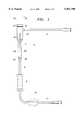
- FIG. 1is a side view of a filter system in accordance with the invention.
- FIG. 2is a vertical cross section of the filter of the system shown in FIG. 1.
- a filter system in accordance with the inventionincludes a gas elimination filter 2, an inlet line 4, an outlet line 6, a pillow-type primer 8, and a tubing clamp 10.
- the inlet and outlet lineshave Luer connectors, which are known in the art and allow the inlet line to be attached to a source of fluids and the outlet line to be attached to a patient line.
- FIG. 2is a vertical cross section of the filter device and shows several features of the invention in more detail.
- An upper part 12is generally cylindrical and forms a vortex chamber 14. While the vortex chamber is preferably cylindrical, it may be other shapes that support formation of a vortex in the inflowing fluid.
- An inlet port 16directs the inflowing fluids into the chamber in a direction tangent to the outer wall of the chamber to form the vortex flow in the fluid. Because of density differences, gasses present in the inflowing fluids separate from the fluids and particulates by the forces in the vortex, the gasses generally accumulating in the central part of the vortex.
- the gassesrise toward the top of the chamber and encounter a hydrophobic membrane 18, which covers the top of the chamber.
- the membrane 18is held to the chamber by a cap formed of two parts.
- the membraneis attached, as by ultrasonic welding, to a first part 20, which is rigid and is sealed to the chamber during assembly.
- a second part 22is flexible and snaps over the first part.
- the first parthas holes 24, which allow passage of the gas that has passed through the membrane. After passage through the holes 24, the gas flows upward over a valve seat 26.
- the flexible cover 22engages the valve seat 26, and an opening 28 in the cover is aligned with the valve seat.
- the gas pressure in the area between the membrane and the flexible coverWhen the gas pressure in the area between the membrane and the flexible cover is greater than atmospheric, the gas will lift the cover from the valve seat, and the gas will exit the device through the hole 24. If, however, the gas pressure in the cap is lower than atmospheric, the cover will be pressed against the valve seat such that air cannot pass through the hole, thus preventing reverse flow of air into the device.
- the coverIn the preferred embodiment, the cover is biased slightly against the seat so that the pressure in the chamber must be greater that atmospheric by a predetermined amount before the cover will be lifted from the seat. This ensures that gas will not be drawn into the chamber when the pressure gradient is very small.
- the fluid flowing into the vortex chamberis illustrated by arrows.
- the fluidforms a strong, descending vortex as it flows into the vortex chamber, and this vortex is allowed to exist for a substantial distance prior to encountering a particulate filter 30.
- the vortex chamberis preferably made of material that allows the operator to view this vortex during operation of the device to verify proper operation, such as a transparent plastic.
- the particulate filteris open at the top whereby a portion of the fluid enters through the center of the particulate filter, and the remainder enters through the side wall of the filter. The vortex flow can continue in the fluid entering through the top, but the vortex action of the fluid is stopped in the main by interaction with the particulate filter.
- the top of the particulate filteris below the center line of the inlet by about 5/8 to 3/4 inch.
- the diameter of the particulate filteris about 40% of the diameter of the vortex chamber.
- the inside diameter of the vortex chamberis about 0.940 inch, and the inside diameter of the particulate filter is about 0.360 inch.
- the particulate filteris preferably made of a material having about 170 ⁇ m mesh to provide superior filtration, and the described design allows this to be used without compromising the flow rate.
- the filteroccupies parts of the vortex chamber and the outlet chamber.
- the particulate filteris about evenly divided between these chambers, and the outside of the particulate filter is sealed to the outer wall of the vortex chamber by a flexible seal 31 to prevent movement of the fluid to the outlet chamber without first passing through the filter.
- Particulates in the fluid in the vortex chamber flowing into the particulate filter through the side wallare removed and accumulate on the exterior of the filter. These particulates generally fall off the outer sides of the filter and accumulate at the bottom of the vortex chamber, as illustrated at 32.
- Applicanthas found that some of the gas not removed in the vortex flow will separate from the fluid as the fluid passes through the filter medium. This gas will either rise on the outside of the filter or accumulate on the side of the filter and eventually become detached. The gas in the fluid that passes through the particulate filter or enters through the top will separate from the fluid in the center of the particulate filter, and that gas will rise to the top of the chamber by passing through the open top of the filter.
- the fluid flowing into the outlet chamber 36 through the particulate filterpasses outwardly through the lower part of the filter medium as it flows into the outlet chamber.
- particulates remaining in the fluid that entered through the open top of the particulate filterare removed by passage through the lower part of the filter medium.
- These particulatesaccumulate on the interior of the filter and often fall off to accumulate in a pile on the bottom of the filter as illustrated at 34.
- the outlet chamber 36is axially aligned with the vortex chamber and is generally of smaller diameter than the vortex chamber. This provides a smaller priming volume in the overall device while still providing adequate diameter for formation of a vortex in the vortex chamber.
- the outlet chamberalso forms a check valve chamber for termination of flow when excess air is present.
- a spherical float 38is located in the outlet chamber for performing the shut-off function. This float in preferably solid, to simplify sterilization and to provide a rigid-to-rigid contact with the valve seat to preclude wedging of the ball into the seat.
- the floatmay be made of a variety of materials and is preferably made of polypropylene.
- the floatoperates in one of two positions. When the outlet chamber is full of air, the float is in the position shown in solid lines in FIG. 2 for termination of fluid flow. When the float is in the position shown in phantom lines, the outlet chamber is full of fluid as in normal operation, and the fluid is flowing freely.
- the bottom of the outlet chamberforms a conical valve seat 40 for engaging the float 38 and terminating fluid flow.
- the sides of the taperpreferably form an angle of about seventy degrees (70°) with the horizontal, which means that the angle between opposed sides of the seat form a forty degree (40°) angle.
- the angle between the opposing sidesshould be no less than thirty five degrees (35°).
- the float itselfis sized such that the engagement between it and the seat occurs in a circle located about 5/8ths of the diameter of the float from the top of the float.
- the check valve of the present inventionhas been designed to provide a very efficient seal that operates effectively in the environment of flowing fluids.
- the angle of the valve seatis large to preclude wedging, the diameter of the ball is large to provide a stable seal, and there is virtually no deformation of the ball during contact between the rigid ball and the seat.
- Applicant's solutionhas been to provide a cage on the bottom of the filter, whereby, as the float rises to assume the position shown in phantom lines, the free-flowing position, it enters the cage formed by one or more fairings 42 that depend from the bottom of the particulate filter.
- fairings 42there are four fairings.
- the bottom of the filterrepresents a stop to prevent further upward movement of the float, and the fairings hold the float centered in the outlet chamber so that it does not become entrained in the fluid flow.
- the fairings 42provide an even flow at a higher flow rate without interference with the float and permit the ball to be larger.
- the operation of the deviceis as follows.
- the inletis attached to a source of physiological fluids for priming, and the clamp 10 is closed. This generally fills the filter device with fluid such that the float rises to the operational position. If the float is stuck, however, the operator will simply depress the pillow 8 one or more times. This action will force air in the outlet line 6 upward into the outlet chamber and dislodge the float from the valve seat. The fluid in the outlet chamber will then cause the float to rise to the operational position, and the air in the system will pass out through the membrane 18 as in normal operation.
- the clamp 10can then be opened to fill the remainder of the line 6 with fluid.
- the relationship between the size of the pillow and the size of the tube extending between the filter device and the pillowis important to whether air expelled from the pillow will be able to lift the float ball from the valve. If the tubing is too large, it will expand when the pillow is depressed, which will decrease the pressure applied to the ball, thus not providing adequate lifting of the float ball. Thus, the expansion capacity of the tube must be less than the volume of the pillow.
- the pillowhas a volume of 12 cc, and the tube between the pillow and the check valve is about 13/4 inches long.
- the tubeis 0.187 inside and 0.265" outside for higher flow rates or 0.130" inside and 0.190 outside for lower flow rates. It will be further appreciated that even though the pillow 8 is an inexpensive element, its positioning below the check valve greatly facilitates setup of the device.
Landscapes
- Health & Medical Sciences (AREA)
- Heart & Thoracic Surgery (AREA)
- Chemical Kinetics & Catalysis (AREA)
- Chemical & Material Sciences (AREA)
- Vascular Medicine (AREA)
- Life Sciences & Earth Sciences (AREA)
- General Health & Medical Sciences (AREA)
- Anesthesiology (AREA)
- Biomedical Technology (AREA)
- Hematology (AREA)
- Cardiology (AREA)
- Animal Behavior & Ethology (AREA)
- Engineering & Computer Science (AREA)
- Public Health (AREA)
- Veterinary Medicine (AREA)
- Filtering Of Dispersed Particles In Gases (AREA)
- Degasification And Air Bubble Elimination (AREA)
- Infusion, Injection, And Reservoir Apparatuses (AREA)
- Respiratory Apparatuses And Protective Means (AREA)
- Check Valves (AREA)
Abstract
Description
This invention relates to the art of filters for removing gas and particulates from fluids, particularly cellular fluids. The invention finds particular utility in the removal of air and particulates from blood during transfusions.
It is often necessary to remove unwanted particles and gasses from fluids by filtering. An example of this is in the infusion of physiological fluids, including blood and blood products. The removal of gasses is even more important when the fluids have been warmed, because of the outgassing caused by the warming.
Because the particles, gasses, and fluid have different densities, it is known to separate these by centrifugal forces arising in a vortex generated in the fluid. Thus, it is known to provide the fluids to a separation chamber by way of an inlet that is tangential to the chamber. The entering fluids are directed into a circular flow pattern, and the gasses tend to accumulate in the center of the chamber while the heavier particles and fluids go to the outside of the chamber. The gasses are allowed to exit the chamber through a vent, and the particles are removed from the fluid by a physical filter.
These devices have faced several problems, particularly when used with cellular fluids. One problem has been the formation of a vortex large enough to remove substantial amounts of gas. The physical arrangement of the various elements of prior devices has constricted the vortex, preventing effective removal of gas. Further, prior art devices have not generally allowed the operator to view operation of the vortex, thus precluding easy verification of proper operation of the device.
Another problem has been clogging due to build up of particulates and cellular globules in the filter medium. This buildup can effectively block the passage of gasses and prevent their separation from the fluid.
A further feature employed in this type of device is that of a check valve. A check valve is placed in the outlet line for stopping further flow through the device when it becomes full of removed air. This occurs, for example, when the amount of air in the fluid exceeds the ability of the device to remove it. Because of the danger of infusing air, or other gasses, into the patient, a check valve that senses the presence of excess air must be placed in the outlet line to block flow of the gasses to the patient. In some instances, these check valves are separate from the filter, which complicates manufacture, inventory, and assembly. Further, prior art check valves often become stuck in the closed position or inhibit fluid flow when open by entrainment of the valve in the fluid flow.
It is an object of this invention to overcome these and other defects by a filter that is compact, easily manufactured, and efficient.
In accordance with the invention, a filter is provided that is capable of removing large amounts of gas, including air, from fluids such as physiological fluids. In overall design, the filter includes a vortex chamber for removal of gasses and an outlet chamber containing a check valve. The vortex and outlet chambers are axially aligned, the outlet chamber being below the vortex chamber. The vortex chamber is preferably cylindrical, but may be of other rotational shapes that will support the swirling flow of a vortex. For example, the vortex chamber may be conical. The vortex chamber has an inlet in the upper part of the vortex chamber for admitting fluids to be filtered to the vortex chamber. The vortex chamber includes a fluid outlet for the filtered fluids in the lower part of the chamber and a gas outlet in the upper part of the chamber for discharging gasses removed from the fluids to the atmosphere. The inlet is directional and is oriented such that the entering fluids flow in a direction that is tangent to the side of the chamber, whereby a vortex is formed as the fluids flow into the chamber. The fluids and particulates are thrown to the outside of the chamber by this vortex, and the gasses accumulate in the center of the vortex chamber.
The removed gasses rise to the top of the vortex chamber and exit to the atmosphere through a hydrophobic membrane that covers the top of the chamber. This membrane is mounted on a solid first part onto which is snapped a flexible cover. The flexible cover has a gas outlet opening that seals against the solid part when the pressure in the container is less than atmospheric and is lifted to release excess gas when the pressure is larger than atmospheric.
The fluids and particulates flow downward and pass to the outlet chamber through a particulate filter that removes particulates from the fluid. This particulate filter is elongate and coaxial with the vortex and outlet chambers and is positioned to extend upward into the vortex chamber and downward into the outlet chamber. The top of the particulate filter is spaced vertically below the inlet by a distance large enough to allow formation of a substantial vortex flow. This construction provides increased filter area and allows the operator to view the functioning of the vortex.
The top of the particulate filter is open to allow gasses separated from the fluids after passing through the particulate filter to rise to the top of the vortex chamber. Thus, the diameter of the vortex chamber is such that in this part of the filter, the upward velocity of the released gas is greater than the downward velocity of the fluid to allow further gas separation. The fluid can flow into the filter through both the open top and the sides of the particulate filter medium. Thus, some of the particulates are removed from the fluid during flow through the sides of the filter medium in the vortex chamber. As the fluid flows into the outlet chamber, it passes through that portion of the particulate filter that extends into the outlet chamber and is filtered further. A fluid seal is provided between the particulate filter and the sides of the filter where the vortex and outlet chambers intersect so that the fluid must flow through the filter as it passes from the vortex chamber to the outlet chamber.
Particulates removed by the particulate filter accumulate on or near the filter medium and then often fall off the filter medium. These removed particulates fall downward where they accumulate in a meniscus shaped pile at the intersection between the bottom of the vortex chamber and the side of the particulate filter. The structure of the invention provides two such locations for these accumulations to occur, thus, decreasing the likelihood that the filter will become clogged with the removed particulates. One such location is on the exterior of the filter at the bottom of the vortex chamber, where it intersects with the outlet chamber. These particulates have been removed as the fluid flows into the filter. The second location is at the bottom of the filter itself where the fluid flows out through the filter medium into the outlet chamber.
The outlet chamber includes a valve seat and a check valve ball, or float, for terminating flow when the outlet chamber contains too much air or other gas. The density of the ball is such that it generally floats in the fluid but falls to the bottom to engage a valve seat when the outlet chamber contains excessive gas. Preferably, the diameter of the float is made large to reduce priming volume further, but this can result in the condition where the upward velocity of the ball is less than the downward velocity of the flowing fluid by entrainment of the ball in the fluid. To prevent this, the bottom of the filter is provided with several fairings that form a cage for receiving the ball and directing the fluid flow around the ball to shield it from the flow. This prevents entrainment of the ball in the downward fluid flow. Thus, during regular flow of the fluid, the ball floats and rises until it engages the bottom of the filter, and the check ball is maintained out of the fluid stream during normal operation of the device by the fairings.
As noted, the ball frequently becomes stuck against the seat and prevents further flow of fluid even after the gas has been evacuated and the outlet is again filled with fluid. Applicant has discovered that operation of a simple priming device creates a reverse flow of the fluid that forces the ball off the valve seat whereby it floats and allows fluid to pass. In the preferred embodiment, this device is a known pillow-type primer that is placed in the outline line just below the outlet chamber. Displacement of the check ball is effected by closing the outlet line below the pillow and squeezing the pillow to cause reverse flow of the fluid to displace the ball from the valve seat.
FIG. 1 is a side view of a filter system in accordance with the invention.
FIG. 2 is a vertical cross section of the filter of the system shown in FIG. 1.
With reference to FIG. 1, a filter system in accordance with the invention includes agas elimination filter 2, aninlet line 4, anoutlet line 6, a pillow-type primer 8, and atubing clamp 10. The inlet and outlet lines have Luer connectors, which are known in the art and allow the inlet line to be attached to a source of fluids and the outlet line to be attached to a patient line.
FIG. 2 is a vertical cross section of the filter device and shows several features of the invention in more detail. Anupper part 12 is generally cylindrical and forms avortex chamber 14. While the vortex chamber is preferably cylindrical, it may be other shapes that support formation of a vortex in the inflowing fluid. Aninlet port 16 directs the inflowing fluids into the chamber in a direction tangent to the outer wall of the chamber to form the vortex flow in the fluid. Because of density differences, gasses present in the inflowing fluids separate from the fluids and particulates by the forces in the vortex, the gasses generally accumulating in the central part of the vortex.
After separation, the gasses rise toward the top of the chamber and encounter ahydrophobic membrane 18, which covers the top of the chamber. Themembrane 18 is held to the chamber by a cap formed of two parts. The membrane is attached, as by ultrasonic welding, to afirst part 20, which is rigid and is sealed to the chamber during assembly. Asecond part 22 is flexible and snaps over the first part. The first part hasholes 24, which allow passage of the gas that has passed through the membrane. After passage through theholes 24, the gas flows upward over avalve seat 26. Theflexible cover 22 engages thevalve seat 26, and anopening 28 in the cover is aligned with the valve seat. When the gas pressure in the area between the membrane and the flexible cover is greater than atmospheric, the gas will lift the cover from the valve seat, and the gas will exit the device through thehole 24. If, however, the gas pressure in the cap is lower than atmospheric, the cover will be pressed against the valve seat such that air cannot pass through the hole, thus preventing reverse flow of air into the device. In the preferred embodiment, the cover is biased slightly against the seat so that the pressure in the chamber must be greater that atmospheric by a predetermined amount before the cover will be lifted from the seat. This ensures that gas will not be drawn into the chamber when the pressure gradient is very small.
The fluid flowing into the vortex chamber is illustrated by arrows. The fluid forms a strong, descending vortex as it flows into the vortex chamber, and this vortex is allowed to exist for a substantial distance prior to encountering aparticulate filter 30. The vortex chamber is preferably made of material that allows the operator to view this vortex during operation of the device to verify proper operation, such as a transparent plastic. As the fluid stream descends, it encounters theparticulate filter 30. The particulate filter is open at the top whereby a portion of the fluid enters through the center of the particulate filter, and the remainder enters through the side wall of the filter. The vortex flow can continue in the fluid entering through the top, but the vortex action of the fluid is stopped in the main by interaction with the particulate filter.
In the preferred embodiment, the top of the particulate filter is below the center line of the inlet by about 5/8 to 3/4 inch. The diameter of the particulate filter is about 40% of the diameter of the vortex chamber. Thus, in the embodiment shown, the inside diameter of the vortex chamber is about 0.940 inch, and the inside diameter of the particulate filter is about 0.360 inch. These dimensions have been found to allow adequate room for establishment of the vortex.
The particulate filter is preferably made of a material having about 170 μm mesh to provide superior filtration, and the described design allows this to be used without compromising the flow rate. The filter occupies parts of the vortex chamber and the outlet chamber. Preferably, the particulate filter is about evenly divided between these chambers, and the outside of the particulate filter is sealed to the outer wall of the vortex chamber by aflexible seal 31 to prevent movement of the fluid to the outlet chamber without first passing through the filter.
Particulates in the fluid in the vortex chamber flowing into the particulate filter through the side wall are removed and accumulate on the exterior of the filter. These particulates generally fall off the outer sides of the filter and accumulate at the bottom of the vortex chamber, as illustrated at 32.
Applicant has found that some of the gas not removed in the vortex flow will separate from the fluid as the fluid passes through the filter medium. This gas will either rise on the outside of the filter or accumulate on the side of the filter and eventually become detached. The gas in the fluid that passes through the particulate filter or enters through the top will separate from the fluid in the center of the particulate filter, and that gas will rise to the top of the chamber by passing through the open top of the filter.
The fluid flowing into theoutlet chamber 36 through the particulate filter passes outwardly through the lower part of the filter medium as it flows into the outlet chamber. Thus, particulates remaining in the fluid that entered through the open top of the particulate filter are removed by passage through the lower part of the filter medium. These particulates accumulate on the interior of the filter and often fall off to accumulate in a pile on the bottom of the filter as illustrated at 34.
It will be appreciated that the above described construction provides a large filter area in a compact device while still allowing formation of a strong vortex in the incoming flow. Moreover, removal of particulates by passage through the two stage filter in both directions allows accumulation of removed particles in two separate locations, which increases the capacity of the filter for a given physical size.
Theoutlet chamber 36 is axially aligned with the vortex chamber and is generally of smaller diameter than the vortex chamber. This provides a smaller priming volume in the overall device while still providing adequate diameter for formation of a vortex in the vortex chamber. The outlet chamber also forms a check valve chamber for termination of flow when excess air is present. Aspherical float 38 is located in the outlet chamber for performing the shut-off function. This float in preferably solid, to simplify sterilization and to provide a rigid-to-rigid contact with the valve seat to preclude wedging of the ball into the seat. The float may be made of a variety of materials and is preferably made of polypropylene.
The float operates in one of two positions. When the outlet chamber is full of air, the float is in the position shown in solid lines in FIG. 2 for termination of fluid flow. When the float is in the position shown in phantom lines, the outlet chamber is full of fluid as in normal operation, and the fluid is flowing freely.
The bottom of the outlet chamber forms aconical valve seat 40 for engaging thefloat 38 and terminating fluid flow. The sides of the taper preferably form an angle of about seventy degrees (70°) with the horizontal, which means that the angle between opposed sides of the seat form a forty degree (40°) angle. The angle between the opposing sides should be no less than thirty five degrees (35°). The float itself is sized such that the engagement between it and the seat occurs in a circle located about 5/8ths of the diameter of the float from the top of the float. These parameters have been found to provide a stable seal that is least likely to stick in the closed position.
The check valve of the present invention has been designed to provide a very efficient seal that operates effectively in the environment of flowing fluids. The angle of the valve seat is large to preclude wedging, the diameter of the ball is large to provide a stable seal, and there is virtually no deformation of the ball during contact between the rigid ball and the seat. These conditions, however, often result in contradictory requirements because a larger ball is more easily caught (entrained) in the downward fluid flow than a smaller ball, and a solid ball is generally less buoyant than a hollow one, which would deform during contact. Applicant's solution has been to provide a cage on the bottom of the filter, whereby, as the float rises to assume the position shown in phantom lines, the free-flowing position, it enters the cage formed by one ormore fairings 42 that depend from the bottom of the particulate filter. In the preferred embodiment, there are four fairings. The bottom of the filter represents a stop to prevent further upward movement of the float, and the fairings hold the float centered in the outlet chamber so that it does not become entrained in the fluid flow. Thus, by guiding the flow of the fluid around the float, thefairings 42 provide an even flow at a higher flow rate without interference with the float and permit the ball to be larger.
With reference to the system shown in FIG. 1, the operation of the device is as follows. The inlet is attached to a source of physiological fluids for priming, and theclamp 10 is closed. This generally fills the filter device with fluid such that the float rises to the operational position. If the float is stuck, however, the operator will simply depress thepillow 8 one or more times. This action will force air in theoutlet line 6 upward into the outlet chamber and dislodge the float from the valve seat. The fluid in the outlet chamber will then cause the float to rise to the operational position, and the air in the system will pass out through themembrane 18 as in normal operation. Theclamp 10 can then be opened to fill the remainder of theline 6 with fluid.
The relationship between the size of the pillow and the size of the tube extending between the filter device and the pillow is important to whether air expelled from the pillow will be able to lift the float ball from the valve. If the tubing is too large, it will expand when the pillow is depressed, which will decrease the pressure applied to the ball, thus not providing adequate lifting of the float ball. Thus, the expansion capacity of the tube must be less than the volume of the pillow. In the preferred embodiment, the pillow has a volume of 12 cc, and the tube between the pillow and the check valve is about 13/4 inches long. The tube is 0.187 inside and 0.265" outside for higher flow rates or 0.130" inside and 0.190 outside for lower flow rates. It will be further appreciated that even though thepillow 8 is an inexpensive element, its positioning below the check valve greatly facilitates setup of the device.
Modifications within the scope of the appended claims will be apparent to those of skill in the art.
Claims (13)
1. A gas elimination filter comprising:
a vortex chamber having an outer wall and an inlet in said outer wall oriented with respect to said outer wall such that a vortex is formed in said vortex chamber by fluid flowing in said inlet,
a tubular particulate filter supported in said vortex chamber such that top of said particulate filter is spaced substantially below said inlet and said vortex is formed in the region between said inlet and said top of said particulate filter, and
an outlet chamber having an outlet for said fluid and being in fluid communication with said vortex chamber, and wherein said particulate filter is open at its top, closed at its bottom and extends into said outlet chamber.
2. A gas elimination filter according to claim 1 wherein at least the portion of said chamber adjacent said region is transparent.
3. A gas elimination filter according to claim 1 wherein
said chamber is cylindrical and said inlet admits said fluid to said chamber in a direction tangent to said chamber.
4. A gas elimination filter according to claim 1 wherein said vortex chamber and said outlet chamber are axially aligned.
5. A gas elimination filter according to claim 1 wherein said filter comprises a filter material in the form of a cylinder that is open at the top to said vortex chamber and closed at the bottom to said outlet chamber, some of said fluid in said vortex chamber passes to said outlet chamber by passing through said open top into the center of said particulate filter and then outwardly through said filter material into said outlet chamber and the remainder of said fluid passes from said vortex chamber inwardly through said filter material into the center of said particulate filter and then outwardly through said filter material to said outlet chamber.
6. A gas elimination filter according to claim 1 wherein said outlet chamber comprises a check valve.
7. A gas elimination filter according to claim 6 wherein said check valve comprises a valve seat formed in a wall of said outlet chamber and a float that engages said seat when said outlet chamber contains excess gas.
8. A gas elimination filter according to claim 7 further comprising a fairing on the bottom of said particulate filter arranged to receive said float when the outlet chamber is full of fluid.
9. A gas elimination filter according to claim 7 further comprising an outlet tube connected at one end to said outlet chamber downstream of said check valve and a primer connected to the opposed end of the outlet tube.
10. A gas elimination filter according to claim 9 wherein said primer is a compressible pillow primer.
11. A gas elimination filter comprising:
vortex chamber means for forming a vortex in a fluid stream for removal of gasses from said fluid,
outlet chamber means for receiving said fluid from said vortex chamber means, and
particulate filter means extending from said vortex chamber means into said outlet chamber means for removing particulates from said fluid stream.
12. A gas elimination filter according to claim 11 wherein said vortex chamber means includes a fluid inlet and said particulate filter is arranged in said vortex chamber such that said vortex forms in a region between said inlet and a top of said particulate filter.
13. A gas elimination filter according to claim 12 wherein said outlet chamber includes a check valve.
Priority Applications (12)
| Application Number | Priority Date | Filing Date | Title |
|---|---|---|---|
| US08/962,596US5961700A (en) | 1997-10-31 | 1997-10-31 | Filter system for removal of gas and particulates from cellular fluids |
| DK98955149TDK1027125T3 (en) | 1997-10-31 | 1998-10-29 | Filter system for removing gas and particles from cellular fluids |
| DE69840605TDE69840605D1 (en) | 1997-10-31 | 1998-10-29 | FILTER DEVICE FOR REMOVING GAS AND PARTICLES FROM CELLULAR FLUIDS |
| CA002301839ACA2301839C (en) | 1997-10-31 | 1998-10-29 | Filter system for removal of gas and particulates from cellular fluids |
| JP2000518764AJP2001521810A (en) | 1997-10-31 | 1998-10-29 | Filter system for removing gases and particulates from cell fluids |
| HK01102821.0AHK1032213B (en) | 1997-10-31 | 1998-10-29 | Filter system for removal of gas and particulates from cellular fluids |
| BR9814829-0ABR9814829A (en) | 1997-10-31 | 1998-10-29 | Gas elimination filter, check valve, and particulate filter |
| AU12025/99AAU1202599A (en) | 1997-10-31 | 1998-10-29 | Filter system for removal of gas and particulates from cellular fluids |
| PCT/US1998/022768WO1999022840A1 (en) | 1997-10-31 | 1998-10-29 | Filter system for removal of gas and particulates from cellular fluids |
| EP98955149AEP1027125B1 (en) | 1997-10-31 | 1998-10-29 | Filter system for removal of gas and particulates from cellular fluids |
| ES98955149TES2320941T3 (en) | 1997-10-31 | 1998-10-29 | FILTER SYSTEM TO REMOVE GAS AND PARTICLES OF CELLULAR FLUIDS. |
| CNB988108402ACN1173763C (en) | 1997-10-31 | 1998-10-29 | Filtration system for removing gas and particulates from cellular fluids |
Applications Claiming Priority (1)
| Application Number | Priority Date | Filing Date | Title |
|---|---|---|---|
| US08/962,596US5961700A (en) | 1997-10-31 | 1997-10-31 | Filter system for removal of gas and particulates from cellular fluids |
Publications (1)
| Publication Number | Publication Date |
|---|---|
| US5961700Atrue US5961700A (en) | 1999-10-05 |
Family
ID=25506115
Family Applications (1)
| Application Number | Title | Priority Date | Filing Date |
|---|---|---|---|
| US08/962,596Expired - LifetimeUS5961700A (en) | 1997-10-31 | 1997-10-31 | Filter system for removal of gas and particulates from cellular fluids |
Country Status (11)
| Country | Link |
|---|---|
| US (1) | US5961700A (en) |
| EP (1) | EP1027125B1 (en) |
| JP (1) | JP2001521810A (en) |
| CN (1) | CN1173763C (en) |
| AU (1) | AU1202599A (en) |
| BR (1) | BR9814829A (en) |
| CA (1) | CA2301839C (en) |
| DE (1) | DE69840605D1 (en) |
| DK (1) | DK1027125T3 (en) |
| ES (1) | ES2320941T3 (en) |
| WO (1) | WO1999022840A1 (en) |
Cited By (29)
| Publication number | Priority date | Publication date | Assignee | Title |
|---|---|---|---|---|
| US6203249B1 (en)* | 1998-09-29 | 2001-03-20 | Mitsui High-Tec Inc. | Particulate objects conveying apparatus for conveying particles of a predetermined size |
| US6467953B1 (en) | 1999-03-30 | 2002-10-22 | Medical Solutions, Inc. | Method and apparatus for monitoring temperature of intravenously delivered fluids and other medical items |
| US6675664B1 (en) | 2001-12-13 | 2004-01-13 | Itt Manufacuring Enterprises, Inc. | Back flushable sample probe |
| US6824528B1 (en) | 1997-03-03 | 2004-11-30 | Medical Solutions, Inc. | Method and apparatus for pressure infusion and temperature control of infused liquids |
| US20050247203A1 (en)* | 2002-06-24 | 2005-11-10 | Jacques Chevallet | Gas separation devices |
| US6981516B1 (en)* | 2002-09-24 | 2006-01-03 | The United States Of America As Represented By The United States Department Of Energy | Fail save shut off valve for filtering systems employing candle filters |
| US7041941B2 (en) | 1997-04-07 | 2006-05-09 | Patented Medical Solutions, Llc | Medical item thermal treatment systems and method of monitoring medical items for compliance with prescribed requirements |
| US20060107837A1 (en)* | 2004-11-22 | 2006-05-25 | Eaton Corporation | Three-phase cyclonic fluid separator |
| US7090658B2 (en) | 1997-03-03 | 2006-08-15 | Medical Solutions, Inc. | Temperature sensing device for selectively measuring temperature at desired locations along an intravenous fluid line |
| US20070173759A1 (en)* | 1999-10-08 | 2007-07-26 | Augustine Scott D | Intravenous fluid warming cassette with stiffening member and integral handle |
| US7276675B2 (en) | 1997-04-07 | 2007-10-02 | Patented Medical Solutions, Llc | Medical item thermal treatment systems and method of monitoring medical items for compliance with prescribed requirements |
| US20080269676A1 (en)* | 2007-04-24 | 2008-10-30 | Arizant Healthcare Inc. | High flow rate infusion with extraction assist |
| US20090173695A1 (en)* | 2004-03-01 | 2009-07-09 | Wieting David W | Method and apparatus for removal of gas bubbles from blood |
| US7611504B1 (en) | 2004-03-09 | 2009-11-03 | Patented Medical Solutions Llc | Method and apparatus for facilitating injection of medication into an intravenous fluid line while maintaining sterility of infused fluids |
| US7740611B2 (en) | 2005-10-27 | 2010-06-22 | Patented Medical Solutions, Llc | Method and apparatus to indicate prior use of a medical item |
| US20120179117A1 (en)* | 2011-01-07 | 2012-07-12 | Hsien-Tsung Wang | Disposable blood transfusion device |
| US8226605B2 (en) | 2001-12-17 | 2012-07-24 | Medical Solutions, Inc. | Method and apparatus for heating solutions within intravenous lines to desired temperatures during infusion |
| US8226293B2 (en) | 2007-02-22 | 2012-07-24 | Medical Solutions, Inc. | Method and apparatus for measurement and control of temperature for infused liquids |
| US9101709B2 (en) | 2002-06-04 | 2015-08-11 | Fresenius Medical Care Deutschland Gmbh | Dialysis fluid cassettes and related systems and methods |
| US9119912B2 (en) | 2001-03-12 | 2015-09-01 | Medical Solutions, Inc. | Method and apparatus for controlling pressurized infusion and temperature of infused liquids |
| US9211381B2 (en) | 2012-01-20 | 2015-12-15 | Medical Solutions, Inc. | Method and apparatus for controlling temperature of medical liquids |
| US9656029B2 (en) | 2013-02-15 | 2017-05-23 | Medical Solutions, Inc. | Plural medical item warming system and method for warming a plurality of medical items to desired temperatures |
| USD820383S1 (en)* | 2016-04-05 | 2018-06-12 | Mitsubishi Chemical Corporation | Degassing/aeration membrane module |
| US20190054255A1 (en)* | 2014-02-14 | 2019-02-21 | Norton Herrick | Gas Removal Systems and Methods |
| US20190126172A1 (en)* | 2017-11-02 | 2019-05-02 | Hydac Technology Corporation | Device for medium separation |
| US10717026B1 (en) | 2019-02-28 | 2020-07-21 | Covenant Testing Technology, LLC | Well production separation systems and methods |
| US11530944B1 (en) | 2019-02-28 | 2022-12-20 | Covenant Testing Technologies, Llc | Well fluid management systems and methods |
| US11590295B2 (en)* | 2018-06-29 | 2023-02-28 | 410 Medical, Inc. | Systems, apparatus, and methods for filtering air from a fluid line |
| US12440629B2 (en) | 2023-02-24 | 2025-10-14 | 410 Medical, Inc. | Systems, apparatus, and methods for filtering air from a fluid line |
Families Citing this family (5)
| Publication number | Priority date | Publication date | Assignee | Title |
|---|---|---|---|---|
| US8518259B2 (en)* | 2011-01-27 | 2013-08-27 | Medtronic, Inc. | De-airing oxygenator for treating blood in an extracorporeal blood circuit |
| TW201332627A (en)* | 2012-02-15 | 2013-08-16 | Asia Ic Mic Process Inc | Bubble removing device for liquid |
| CN106164241A (en)* | 2014-03-28 | 2016-11-23 | 日立化成株式会社 | Cell capture device, with the cell capture device in pre-treatment portion and pre-treatment portion |
| DE102014014725A1 (en)* | 2014-10-02 | 2016-04-07 | Resuscitec Gmbh | Device with a bag-shaped container and method for gas bubble-free filling of a pump-driven, hollow-line-supported liquid circuit by means of the device |
| DE102016122660A1 (en)* | 2016-11-24 | 2018-05-24 | B. Braun Avitum Ag | Medical air separator for use in blood treatments |
Citations (38)
| Publication number | Priority date | Publication date | Assignee | Title |
|---|---|---|---|---|
| US2784733A (en)* | 1954-10-08 | 1957-03-12 | Baxter Don Inc | Check valve for parenteral solutions |
| US2879784A (en)* | 1954-03-08 | 1959-03-31 | Cutter Lab | Check valve for the administration of parenteral solutions |
| US3105511A (en)* | 1961-08-10 | 1963-10-01 | Cordis Corp | Infusion safety valve |
| US3276188A (en)* | 1964-02-28 | 1966-10-04 | Itt | Heating or cooling systems and air separating devices therefor |
| US3476251A (en)* | 1966-05-04 | 1969-11-04 | Marvel Eng Co | Filter and housing structure |
| US3512940A (en)* | 1968-12-30 | 1970-05-19 | Justin J Shapiro | Test tube filter device |
| US3616802A (en)* | 1969-08-20 | 1971-11-02 | Frank A Marinaccio | Filtering device |
| US3771290A (en)* | 1971-12-06 | 1973-11-13 | Armstrong Ltd S A | Vortex de-aerator |
| US3834126A (en)* | 1973-01-26 | 1974-09-10 | United Aircraft Corp | Water separator |
| US3993062A (en)* | 1975-11-03 | 1976-11-23 | Baxter Laboratories, Inc. | Hydrophobic valve |
| US4004587A (en)* | 1975-06-13 | 1977-01-25 | Baxter Travenol Laboratories, Inc. | Parenteral liquid administration set with non-air blocking filter |
| US4013072A (en)* | 1975-11-03 | 1977-03-22 | Baxter Travenol Laboratories, Inc. | Drip chamber for intravenous administration |
| US4028254A (en)* | 1975-10-14 | 1977-06-07 | Nupro Company | Fluid filter |
| US4102655A (en)* | 1977-05-02 | 1978-07-25 | Cobe Laboratories, Inc. | Bubble trap |
| US4345919A (en)* | 1981-01-19 | 1982-08-24 | Texas Medical Products, Inc. | Degasser for biological fluids |
| US4365980A (en)* | 1981-08-20 | 1982-12-28 | Farr Company | Air filter assembly |
| US4368118A (en)* | 1980-01-07 | 1983-01-11 | Siposs George G | Blood-air separator and filter |
| US4411783A (en)* | 1981-12-23 | 1983-10-25 | Shiley Incorporated | Arterial blood filter with improved gas venting |
| US4448206A (en)* | 1981-08-17 | 1984-05-15 | Martell Michael D | Vented, aspirating syringe |
| US4492634A (en)* | 1982-09-28 | 1985-01-08 | Emde Medical Research | Pre-evacuated blood collection tube with anti-hemolysis baffle system and centrifugation propelled filtration disc and efficient serum-from cells separator |
| US4572724A (en)* | 1984-04-12 | 1986-02-25 | Pall Corporation | Blood filter |
| US4601712A (en)* | 1983-11-16 | 1986-07-22 | Gould Inc. | Drip chamber |
| US4690762A (en)* | 1983-06-10 | 1987-09-01 | Terumo Kabushiki Kaisha | Apparatus for removing bubbles from a liquid |
| US4758337A (en)* | 1985-11-23 | 1988-07-19 | Sartorius Gmbh | Filter for filtering human blood, especially in an extracorporeal circulatory system |
| US4761232A (en)* | 1986-03-07 | 1988-08-02 | Porex Technologies Corp. Of Georgia | Macroporous substrate containing microporous matrix |
| US4806135A (en)* | 1988-03-01 | 1989-02-21 | Siposs George G | Bubble trap for phase-separating gas bubbles from flowing liquids |
| US4870987A (en)* | 1988-07-22 | 1989-10-03 | Cheng Ton Lin | Relating to a flow regulator for intravenous injection device |
| US4900308A (en)* | 1987-05-27 | 1990-02-13 | Level 1 Technologies, Inc. | Gas elimination device |
| US4919802A (en)* | 1987-12-04 | 1990-04-24 | Terumo Kabushiki Kaisha | Blood filter |
| DE3837896A1 (en)* | 1988-11-08 | 1990-05-10 | Evelin Kronawitter | Infusion device |
| US4932987A (en)* | 1989-05-25 | 1990-06-12 | Jorge Molina | Extra corporeal air eliminator |
| US4964984A (en)* | 1989-06-14 | 1990-10-23 | Electromedics, Inc. | Blood filter |
| US5045096A (en)* | 1988-09-21 | 1991-09-03 | Quang Minh B | Devices for de-aerating liquids flowing in medical liquid systems |
| US5224515A (en)* | 1992-01-30 | 1993-07-06 | Porex Technologies Corp. | Tube closure |
| US5429595A (en)* | 1992-11-12 | 1995-07-04 | Wright, Jr.; Fred G. | Arterial safety air diverter |
| US5484474A (en)* | 1993-04-23 | 1996-01-16 | C.R. Bard, Inc. | Inverted dome arterial filter |
| US5514095A (en)* | 1994-04-04 | 1996-05-07 | Haemonetics Corporation | Apparatus for heating, filtering and eliminating gas from biological fluids |
| US5707431A (en)* | 1994-02-15 | 1998-01-13 | Sims Level 1, Inc. | Vortex gas elimination device |
- 1997
- 1997-10-31USUS08/962,596patent/US5961700A/ennot_activeExpired - Lifetime
- 1998
- 1998-10-29CACA002301839Apatent/CA2301839C/ennot_activeExpired - Fee Related
- 1998-10-29DEDE69840605Tpatent/DE69840605D1/ennot_activeExpired - Lifetime
- 1998-10-29EPEP98955149Apatent/EP1027125B1/ennot_activeExpired - Lifetime
- 1998-10-29CNCNB988108402Apatent/CN1173763C/ennot_activeExpired - Fee Related
- 1998-10-29BRBR9814829-0Apatent/BR9814829A/ennot_activeIP Right Cessation
- 1998-10-29DKDK98955149Tpatent/DK1027125T3/enactive
- 1998-10-29ESES98955149Tpatent/ES2320941T3/ennot_activeExpired - Lifetime
- 1998-10-29WOPCT/US1998/022768patent/WO1999022840A1/enactiveApplication Filing
- 1998-10-29AUAU12025/99Apatent/AU1202599A/ennot_activeAbandoned
- 1998-10-29JPJP2000518764Apatent/JP2001521810A/enactivePending
Patent Citations (39)
| Publication number | Priority date | Publication date | Assignee | Title |
|---|---|---|---|---|
| US2879784A (en)* | 1954-03-08 | 1959-03-31 | Cutter Lab | Check valve for the administration of parenteral solutions |
| US2784733A (en)* | 1954-10-08 | 1957-03-12 | Baxter Don Inc | Check valve for parenteral solutions |
| US3105511A (en)* | 1961-08-10 | 1963-10-01 | Cordis Corp | Infusion safety valve |
| US3276188A (en)* | 1964-02-28 | 1966-10-04 | Itt | Heating or cooling systems and air separating devices therefor |
| US3476251A (en)* | 1966-05-04 | 1969-11-04 | Marvel Eng Co | Filter and housing structure |
| US3512940A (en)* | 1968-12-30 | 1970-05-19 | Justin J Shapiro | Test tube filter device |
| US3616802A (en)* | 1969-08-20 | 1971-11-02 | Frank A Marinaccio | Filtering device |
| US3771290A (en)* | 1971-12-06 | 1973-11-13 | Armstrong Ltd S A | Vortex de-aerator |
| US3834126A (en)* | 1973-01-26 | 1974-09-10 | United Aircraft Corp | Water separator |
| US4004587A (en)* | 1975-06-13 | 1977-01-25 | Baxter Travenol Laboratories, Inc. | Parenteral liquid administration set with non-air blocking filter |
| US4028254A (en)* | 1975-10-14 | 1977-06-07 | Nupro Company | Fluid filter |
| US3993062A (en)* | 1975-11-03 | 1976-11-23 | Baxter Laboratories, Inc. | Hydrophobic valve |
| US4013072A (en)* | 1975-11-03 | 1977-03-22 | Baxter Travenol Laboratories, Inc. | Drip chamber for intravenous administration |
| US4102655A (en)* | 1977-05-02 | 1978-07-25 | Cobe Laboratories, Inc. | Bubble trap |
| US4368118A (en)* | 1980-01-07 | 1983-01-11 | Siposs George G | Blood-air separator and filter |
| US4345919A (en)* | 1981-01-19 | 1982-08-24 | Texas Medical Products, Inc. | Degasser for biological fluids |
| US4448206A (en)* | 1981-08-17 | 1984-05-15 | Martell Michael D | Vented, aspirating syringe |
| US4365980A (en)* | 1981-08-20 | 1982-12-28 | Farr Company | Air filter assembly |
| US4411783A (en)* | 1981-12-23 | 1983-10-25 | Shiley Incorporated | Arterial blood filter with improved gas venting |
| US4492634A (en)* | 1982-09-28 | 1985-01-08 | Emde Medical Research | Pre-evacuated blood collection tube with anti-hemolysis baffle system and centrifugation propelled filtration disc and efficient serum-from cells separator |
| US4690762A (en)* | 1983-06-10 | 1987-09-01 | Terumo Kabushiki Kaisha | Apparatus for removing bubbles from a liquid |
| US4601712A (en)* | 1983-11-16 | 1986-07-22 | Gould Inc. | Drip chamber |
| US4572724A (en)* | 1984-04-12 | 1986-02-25 | Pall Corporation | Blood filter |
| US4662906A (en)* | 1984-04-12 | 1987-05-05 | Pall Corporation | Cardiotomy reservoir |
| US4758337A (en)* | 1985-11-23 | 1988-07-19 | Sartorius Gmbh | Filter for filtering human blood, especially in an extracorporeal circulatory system |
| US4761232A (en)* | 1986-03-07 | 1988-08-02 | Porex Technologies Corp. Of Georgia | Macroporous substrate containing microporous matrix |
| US4900308A (en)* | 1987-05-27 | 1990-02-13 | Level 1 Technologies, Inc. | Gas elimination device |
| US4919802A (en)* | 1987-12-04 | 1990-04-24 | Terumo Kabushiki Kaisha | Blood filter |
| US4806135A (en)* | 1988-03-01 | 1989-02-21 | Siposs George G | Bubble trap for phase-separating gas bubbles from flowing liquids |
| US4870987A (en)* | 1988-07-22 | 1989-10-03 | Cheng Ton Lin | Relating to a flow regulator for intravenous injection device |
| US5045096A (en)* | 1988-09-21 | 1991-09-03 | Quang Minh B | Devices for de-aerating liquids flowing in medical liquid systems |
| DE3837896A1 (en)* | 1988-11-08 | 1990-05-10 | Evelin Kronawitter | Infusion device |
| US4932987A (en)* | 1989-05-25 | 1990-06-12 | Jorge Molina | Extra corporeal air eliminator |
| US4964984A (en)* | 1989-06-14 | 1990-10-23 | Electromedics, Inc. | Blood filter |
| US5224515A (en)* | 1992-01-30 | 1993-07-06 | Porex Technologies Corp. | Tube closure |
| US5429595A (en)* | 1992-11-12 | 1995-07-04 | Wright, Jr.; Fred G. | Arterial safety air diverter |
| US5484474A (en)* | 1993-04-23 | 1996-01-16 | C.R. Bard, Inc. | Inverted dome arterial filter |
| US5707431A (en)* | 1994-02-15 | 1998-01-13 | Sims Level 1, Inc. | Vortex gas elimination device |
| US5514095A (en)* | 1994-04-04 | 1996-05-07 | Haemonetics Corporation | Apparatus for heating, filtering and eliminating gas from biological fluids |
Cited By (72)
| Publication number | Priority date | Publication date | Assignee | Title |
|---|---|---|---|---|
| US7090658B2 (en) | 1997-03-03 | 2006-08-15 | Medical Solutions, Inc. | Temperature sensing device for selectively measuring temperature at desired locations along an intravenous fluid line |
| US7540864B2 (en) | 1997-03-03 | 2009-06-02 | Medical Solutions, Inc. | Temperature sensing device for selectively measuring temperature at desired locations along an intravenous fluid line |
| US8313462B2 (en) | 1997-03-03 | 2012-11-20 | Medical Solutions, Inc. | Method and apparatus for pressure infusion and temperature control of infused liquids |
| US7942851B2 (en) | 1997-03-03 | 2011-05-17 | Medical Solutions, Inc. | Method and apparatus for pressure infusion and temperature control of infused liquids |
| US6824528B1 (en) | 1997-03-03 | 2004-11-30 | Medical Solutions, Inc. | Method and apparatus for pressure infusion and temperature control of infused liquids |
| US8920387B2 (en) | 1997-03-03 | 2014-12-30 | Medical Solutions, Inc. | Method and apparatus for pressure infusion and temperature control of infused liquids |
| US7417205B2 (en) | 1997-04-07 | 2008-08-26 | Patented Medical Solutions, Llc | Medical item thermal treatment systems and method of monitoring medical items for compliance with prescribed requirements |
| US7307245B2 (en) | 1997-04-07 | 2007-12-11 | Patented Medical Solutions, Llc | Medical item thermal treatment systems and method of monitoring medical items for compliance with prescribed requirements |
| US7276675B2 (en) | 1997-04-07 | 2007-10-02 | Patented Medical Solutions, Llc | Medical item thermal treatment systems and method of monitoring medical items for compliance with prescribed requirements |
| US7041941B2 (en) | 1997-04-07 | 2006-05-09 | Patented Medical Solutions, Llc | Medical item thermal treatment systems and method of monitoring medical items for compliance with prescribed requirements |
| US6203249B1 (en)* | 1998-09-29 | 2001-03-20 | Mitsui High-Tec Inc. | Particulate objects conveying apparatus for conveying particles of a predetermined size |
| US6325571B1 (en) | 1998-09-29 | 2001-12-04 | Mitsui High-Tec Inc. | Particulate object conveying apparatus |
| US6566631B2 (en) | 1999-03-30 | 2003-05-20 | Medical Solutions, Inc. | Method and apparatus for monitoring temperature of intravenously delivered fluids and other medical items |
| US8821011B2 (en) | 1999-03-30 | 2014-09-02 | Medical Solutions, Inc. | Method and apparatus for monitoring temperature of intravenously delivered fluids and other medical items |
| US6467953B1 (en) | 1999-03-30 | 2002-10-22 | Medical Solutions, Inc. | Method and apparatus for monitoring temperature of intravenously delivered fluids and other medical items |
| US6722782B2 (en) | 1999-03-30 | 2004-04-20 | Medical Solutions, Inc. | Method and apparatus for monitoring temperature of intravenously delivered fluids and other medical items |
| US7853131B2 (en) | 1999-10-08 | 2010-12-14 | Arizant Healthcare Inc. | Intravenous fluid warming cassette |
| US20070173759A1 (en)* | 1999-10-08 | 2007-07-26 | Augustine Scott D | Intravenous fluid warming cassette with stiffening member and integral handle |
| US20110046551A1 (en)* | 1999-10-08 | 2011-02-24 | Arizant Healthcare Inc. | Intravenous fluid warming cassette system |
| US9119912B2 (en) | 2001-03-12 | 2015-09-01 | Medical Solutions, Inc. | Method and apparatus for controlling pressurized infusion and temperature of infused liquids |
| US6675664B1 (en) | 2001-12-13 | 2004-01-13 | Itt Manufacuring Enterprises, Inc. | Back flushable sample probe |
| US9492624B2 (en) | 2001-12-17 | 2016-11-15 | Medical Solutions, Inc. | Method and apparatus for heating solutions within intravenous lines to desired temperatures during infusion |
| US8226605B2 (en) | 2001-12-17 | 2012-07-24 | Medical Solutions, Inc. | Method and apparatus for heating solutions within intravenous lines to desired temperatures during infusion |
| US8920372B2 (en) | 2001-12-17 | 2014-12-30 | Medical Solutions, Inc. | Method and apparatus for heating solutions within intravenous lines to desired temperatures during infusion |
| US9101709B2 (en) | 2002-06-04 | 2015-08-11 | Fresenius Medical Care Deutschland Gmbh | Dialysis fluid cassettes and related systems and methods |
| US7517387B2 (en) | 2002-06-24 | 2009-04-14 | Gambro Lundia Ab | Gas separation devices |
| US20050247203A1 (en)* | 2002-06-24 | 2005-11-10 | Jacques Chevallet | Gas separation devices |
| US6981516B1 (en)* | 2002-09-24 | 2006-01-03 | The United States Of America As Represented By The United States Department Of Energy | Fail save shut off valve for filtering systems employing candle filters |
| US20110054380A1 (en)* | 2003-02-13 | 2011-03-03 | Wieting David W | Method and apparatus for removal of gas bubbles from blood |
| US8480606B2 (en) | 2003-02-13 | 2013-07-09 | Indian Wells Medical, Inc. | Method and apparatus for removal of gas bubbles from blood |
| US7824356B2 (en)* | 2004-03-01 | 2010-11-02 | Indian Wells Medical, Inc. | Method and apparatus for removal of gas bubbles from blood |
| US8939926B2 (en)* | 2004-03-01 | 2015-01-27 | Indian Wells Medical, Inc. | Method and apparatus for removal of gas bubbles from blood |
| US20090173695A1 (en)* | 2004-03-01 | 2009-07-09 | Wieting David W | Method and apparatus for removal of gas bubbles from blood |
| US10369265B2 (en)* | 2004-03-01 | 2019-08-06 | Indian Wells Medical, Inc. | Method and apparatus for removal of gas bubbles from fluid |
| US20130338561A1 (en)* | 2004-03-01 | 2013-12-19 | Indian Wells Medical, Inc. | Method and apparatus for removal of gas bubbles from blood |
| US8845586B2 (en) | 2004-03-09 | 2014-09-30 | Patented Medical Solutions Llc | Method and apparatus for facilitating injection of medication into an intravenous fluid line while maintaining sterility of infused fluids |
| US7611504B1 (en) | 2004-03-09 | 2009-11-03 | Patented Medical Solutions Llc | Method and apparatus for facilitating injection of medication into an intravenous fluid line while maintaining sterility of infused fluids |
| US7288138B2 (en)* | 2004-11-22 | 2007-10-30 | Eaton Corporation | Three-phase cyclonic fluid separator |
| US20060107837A1 (en)* | 2004-11-22 | 2006-05-25 | Eaton Corporation | Three-phase cyclonic fluid separator |
| US7740611B2 (en) | 2005-10-27 | 2010-06-22 | Patented Medical Solutions, Llc | Method and apparatus to indicate prior use of a medical item |
| US8636691B2 (en) | 2005-10-27 | 2014-01-28 | Patented Medical Solutions, Llc | Method and apparatus to indicate prior use of a medical item |
| US8444599B2 (en) | 2005-10-27 | 2013-05-21 | Patented Medical Solutions, Llc | Method and apparatus to indicate prior use of a medical item |
| US8226293B2 (en) | 2007-02-22 | 2012-07-24 | Medical Solutions, Inc. | Method and apparatus for measurement and control of temperature for infused liquids |
| US20080269679A1 (en)* | 2007-04-24 | 2008-10-30 | Arizant Healthcare Inc. | Bubble trap for high flow rate infusion |
| US20080269663A1 (en)* | 2007-04-24 | 2008-10-30 | Arizant Healthcare Inc. | High flow rate infusion unit and heat exchanger |
| US8385731B2 (en) | 2007-04-24 | 2013-02-26 | Arizant Healthcare Inc. | Heat exchanger for high flow rate infusion |
| US8241409B2 (en) | 2007-04-24 | 2012-08-14 | Arizant Healthcare Inc. | Bubble trap for high flow rate infusion |
| US20080269676A1 (en)* | 2007-04-24 | 2008-10-30 | Arizant Healthcare Inc. | High flow rate infusion with extraction assist |
| US8180206B2 (en) | 2007-04-24 | 2012-05-15 | Arizant Healthcare Inc. | High flow rate infusion with extraction assist |
| US7983540B2 (en) | 2007-04-24 | 2011-07-19 | Arizant Healthcare Inc. | Heat exchanger for high flow rate infusion |
| US7927302B2 (en) | 2007-04-24 | 2011-04-19 | Arizant Healthcare Inc. | High flow rate infusion unit and heat exchanger |
| US20100300293A1 (en)* | 2007-04-24 | 2010-12-02 | Arizant Healthcare Inc. | Bubble trap for high flow rate infusion |
| US7803217B2 (en) | 2007-04-24 | 2010-09-28 | Arizant Healthcare, Inc. | Bubble trap for high flow rate infusion |
| US20100222737A1 (en)* | 2007-04-24 | 2010-09-02 | Arizant Healthcare Inc. | High flow rate infusion unit and heat exchanger |
| US20100185149A1 (en)* | 2007-04-24 | 2010-07-22 | Arizant Healthcare Inc. | Heat exchanger for high flow rate infusion |
| US7720362B2 (en) | 2007-04-24 | 2010-05-18 | Arizant Healthcare Inc. | Heat exchanger for high flow rate infusion |
| US20080267599A1 (en)* | 2007-04-24 | 2008-10-30 | Arizant Healthcare Inc. | Heat exchanger for high flow rate infusion |
| US20120179117A1 (en)* | 2011-01-07 | 2012-07-12 | Hsien-Tsung Wang | Disposable blood transfusion device |
| US8328770B2 (en)* | 2011-01-07 | 2012-12-11 | Hsien-Tsung Wang | Disposable blood transfusion device |
| US9764100B2 (en) | 2012-01-20 | 2017-09-19 | Medical Solutions, Inc. | Method and apparatus for controlling temperature of medical liquids |
| US9211381B2 (en) | 2012-01-20 | 2015-12-15 | Medical Solutions, Inc. | Method and apparatus for controlling temperature of medical liquids |
| US9656029B2 (en) | 2013-02-15 | 2017-05-23 | Medical Solutions, Inc. | Plural medical item warming system and method for warming a plurality of medical items to desired temperatures |
| US10869972B2 (en)* | 2014-02-14 | 2020-12-22 | Ailnh, Llc | Gas removal systems and methods |
| US20190054255A1 (en)* | 2014-02-14 | 2019-02-21 | Norton Herrick | Gas Removal Systems and Methods |
| US20210106769A1 (en)* | 2014-02-14 | 2021-04-15 | Ailnh, Llc | Gas Removal Systems and Methods |
| USD820383S1 (en)* | 2016-04-05 | 2018-06-12 | Mitsubishi Chemical Corporation | Degassing/aeration membrane module |
| US20190126172A1 (en)* | 2017-11-02 | 2019-05-02 | Hydac Technology Corporation | Device for medium separation |
| US10918973B2 (en)* | 2017-11-02 | 2021-02-16 | Hydac Technology Corporation | Device for medium separation |
| US11590295B2 (en)* | 2018-06-29 | 2023-02-28 | 410 Medical, Inc. | Systems, apparatus, and methods for filtering air from a fluid line |
| US10717026B1 (en) | 2019-02-28 | 2020-07-21 | Covenant Testing Technology, LLC | Well production separation systems and methods |
| US11530944B1 (en) | 2019-02-28 | 2022-12-20 | Covenant Testing Technologies, Llc | Well fluid management systems and methods |
| US12440629B2 (en) | 2023-02-24 | 2025-10-14 | 410 Medical, Inc. | Systems, apparatus, and methods for filtering air from a fluid line |
Also Published As
| Publication number | Publication date |
|---|---|
| DE69840605D1 (en) | 2009-04-09 |
| JP2001521810A (en) | 2001-11-13 |
| BR9814829A (en) | 2000-10-03 |
| EP1027125A4 (en) | 2000-12-27 |
| EP1027125B1 (en) | 2009-02-25 |
| EP1027125A1 (en) | 2000-08-16 |
| WO1999022840A1 (en) | 1999-05-14 |
| ES2320941T3 (en) | 2009-05-29 |
| CN1278190A (en) | 2000-12-27 |
| CN1173763C (en) | 2004-11-03 |
| HK1032213A1 (en) | 2001-07-13 |
| AU1202599A (en) | 1999-05-24 |
| DK1027125T3 (en) | 2009-05-18 |
| CA2301839C (en) | 2007-09-18 |
| CA2301839A1 (en) | 1999-05-14 |
Similar Documents
| Publication | Publication Date | Title |
|---|---|---|
| US5961700A (en) | Filter system for removal of gas and particulates from cellular fluids | |
| US4806135A (en) | Bubble trap for phase-separating gas bubbles from flowing liquids | |
| US4368118A (en) | Blood-air separator and filter | |
| JP5474826B2 (en) | Vent valve assembly | |
| US5674200A (en) | Air eliminator | |
| US5707431A (en) | Vortex gas elimination device | |
| US6176903B1 (en) | Device for removing gases from fluids | |
| US4344777A (en) | Directed flow bubble trap for arterial blood | |
| US5503801A (en) | Top flow bubble trap apparatus | |
| AU624630B2 (en) | Blood filter | |
| US5632894A (en) | Arterial blood filter with upwardly inclining delivery inlet conduit | |
| EP1084722B1 (en) | Arterial blood filter | |
| JP5379792B2 (en) | Filter assembly and method | |
| JP4974129B2 (en) | Filtration device for liquid | |
| CA1054073A (en) | Gas purging fluid filter | |
| JP2006223871A (en) | Pressure operated endovascular set with drip chamber access | |
| JPH0121988B2 (en) | ||
| JP2000509620A (en) | Drip chamber for removing gas from liquid | |
| JPH01148266A (en) | Blood filter | |
| GB2063108A (en) | Degassing device | |
| KR101042037B1 (en) | Filtration | |
| US3289839A (en) | Filtering equipment for fluids | |
| US3656505A (en) | Automatic cut-off for intravenous equipment | |
| WO1993025248A1 (en) | Medical suction controller jar | |
| HK1032213B (en) | Filter system for removal of gas and particulates from cellular fluids |
Legal Events
| Date | Code | Title | Description |
|---|---|---|---|
| AS | Assignment | Owner name:SIMS LEVEL I, INC., MASSACHUSETTS Free format text:ASSIGNMENT OF ASSIGNORS INTEREST;ASSIGNOR:OLIVER, DANA A.;REEL/FRAME:009175/0274 Effective date:19980424 | |
| STCF | Information on status: patent grant | Free format text:PATENTED CASE | |
| AS | Assignment | Owner name:LEVEL 1, INC., MASSACHUSETTS Free format text:CHANGE OF NAME;ASSIGNOR:SIMS LEVEL 1, INC.;REEL/FRAME:012721/0875 Effective date:20010701 | |
| FPAY | Fee payment | Year of fee payment:4 | |
| AS | Assignment | Owner name:SMITHS MEDICAL ASD, INC., NEW HAMPSHIRE Free format text:CHANGE OF NAME;ASSIGNOR:LEVEL 1, INC.;REEL/FRAME:015044/0700 Effective date:20031222 | |
| FPAY | Fee payment | Year of fee payment:8 | |
| FPAY | Fee payment | Year of fee payment:12 |