US5961532A - Surgical tool having flexible tubular inner member movable for tissue working - Google Patents
Surgical tool having flexible tubular inner member movable for tissue workingDownload PDFInfo
- Publication number
- US5961532A US5961532AUS08/919,565US91956597AUS5961532AUS 5961532 AUS5961532 AUS 5961532AUS 91956597 AUS91956597 AUS 91956597AUS 5961532 AUS5961532 AUS 5961532A
- Authority
- US
- United States
- Prior art keywords
- inner tube
- annular flange
- recess
- tubular member
- working tip
- Prior art date
- Legal status (The legal status is an assumption and is not a legal conclusion. Google has not performed a legal analysis and makes no representation as to the accuracy of the status listed.)
- Expired - Lifetime
Links
- 239000002861polymer materialSubstances0.000claimsabstractdescription12
- 229920005570flexible polymerPolymers0.000claimsabstractdescription4
- 239000000463materialSubstances0.000claimsdescription16
- 239000000853adhesiveSubstances0.000claimsdescription11
- 230000001070adhesive effectEffects0.000claimsdescription11
- 239000004696Poly ether ether ketoneSubstances0.000claimsdescription7
- 229920002530polyetherether ketonePolymers0.000claimsdescription7
- 229910001220stainless steelInorganic materials0.000claimsdescription5
- 239000010935stainless steelSubstances0.000claimsdescription5
- 210000001519tissueAnatomy0.000description14
- 230000002093peripheral effectEffects0.000description12
- 238000005520cutting processMethods0.000description10
- 238000001356surgical procedureMethods0.000description8
- 238000010008shearingMethods0.000description6
- 239000012634fragmentSubstances0.000description5
- 238000003780insertionMethods0.000description5
- 230000037431insertionEffects0.000description5
- 229920000642polymerPolymers0.000description5
- 230000009969flowable effectEffects0.000description3
- 239000002184metalSubstances0.000description3
- 239000004033plasticSubstances0.000description3
- 229920003023plasticPolymers0.000description3
- 229920006332epoxy adhesivePolymers0.000description2
- 210000003127kneeAnatomy0.000description2
- 239000007788liquidSubstances0.000description2
- 238000003754machiningMethods0.000description2
- 238000000034methodMethods0.000description2
- 239000004417polycarbonateSubstances0.000description2
- 229920000515polycarbonatePolymers0.000description2
- 229920001169thermoplasticPolymers0.000description2
- 239000004416thermosoftening plasticSubstances0.000description2
- 238000013459approachMethods0.000description1
- 238000005452bendingMethods0.000description1
- 230000015572biosynthetic processEffects0.000description1
- 210000000845cartilageAnatomy0.000description1
- 238000004891communicationMethods0.000description1
- 230000000295complement effectEffects0.000description1
- 230000006835compressionEffects0.000description1
- 238000007906compressionMethods0.000description1
- 238000010276constructionMethods0.000description1
- 238000012976endoscopic surgical procedureMethods0.000description1
- 239000003822epoxy resinSubstances0.000description1
- 239000012530fluidSubstances0.000description1
- 238000010438heat treatmentMethods0.000description1
- 230000002262irrigationEffects0.000description1
- 238000003973irrigationMethods0.000description1
- 238000004519manufacturing processMethods0.000description1
- 230000005499meniscusEffects0.000description1
- 238000012986modificationMethods0.000description1
- 230000004048modificationEffects0.000description1
- 239000002991molded plasticSubstances0.000description1
- 229920000647polyepoxidePolymers0.000description1
- 230000008707rearrangementEffects0.000description1
- 239000012815thermoplastic materialSubstances0.000description1
- 238000009966trimmingMethods0.000description1
Images


Classifications
- A—HUMAN NECESSITIES
- A61—MEDICAL OR VETERINARY SCIENCE; HYGIENE
- A61B—DIAGNOSIS; SURGERY; IDENTIFICATION
- A61B17/00—Surgical instruments, devices or methods
- A61B17/32—Surgical cutting instruments
- A61B17/320016—Endoscopic cutting instruments, e.g. arthroscopes, resectoscopes
- A61B17/32002—Endoscopic cutting instruments, e.g. arthroscopes, resectoscopes with continuously rotating, oscillating or reciprocating cutting instruments
- A—HUMAN NECESSITIES
- A61—MEDICAL OR VETERINARY SCIENCE; HYGIENE
- A61B—DIAGNOSIS; SURGERY; IDENTIFICATION
- A61B90/00—Instruments, implements or accessories specially adapted for surgery or diagnosis and not covered by any of the groups A61B1/00 - A61B50/00, e.g. for luxation treatment or for protecting wound edges
- A61B90/03—Automatic limiting or abutting means, e.g. for safety
- A61B2090/037—Automatic limiting or abutting means, e.g. for safety with a frangible part, e.g. by reduced diameter
Definitions
- This inventionrelates to a surgical tool having a flexible tubular inner member movable for tissue working.
- surgical toolssuch as cutters and burs
- Such toolstypically include an elongate tubular outer member releasably fixable to the housing of a handpiece and containing an elongate tubular inner member movable therein by a motor in the handpiece.
- the inner memberis rotatable within the outer member and the distal end portion of the inner member defines a tissue working tip engagable with patient tissue through a window in the distal end portion of the tubular outer member.
- the tipcomprises, for example, a bur, a shearing edge coactive with corresponding shearing edge in the outer member window, or other patient tissue working structure.
- Tools of this typehave normally been straight. However, in certain surgical procedures it is convenient if such a tool is bent at a location spaced intermediate the ends of the outer tubular member.
- a tool with an angled outer tubular memberrequires, however, that the inner tubular member be capable of flexing as it moves within the outer tubular member. This can be particularly difficult to achieve in an operational tool where the inner tubular member rotates within the outer tubular member, particularly at speeds at several thousand RPM.
- U.S. Pat. No. 5,437,630(Daniel, et al.) assigned to Stryker Corporation, the present Assignee, discloses an inner member in which the flexible portion is not tubular but rather is, a central structure spaced radially inboard of the peripheral wall of the outer tubular member.
- U.S. Pat. No. 5,540,708(Lim, et al.) assigned to Linvatec Corporation, discloses such a tool in which the flexible inner rotatable tubular member includes a metal tip, provided with a toothed window cooperable in rotative shearing relation with a corresponding shearing window in the distal end portion of the bent rigid outer tube.
- the inner tubular memberfurther includes a proximal rigid plastic hub, the tip and hub being spaced by an elongate hollow tube of polymer material, for example PEEK (polyetheretherketone).
- the structure of the joinder of the tip to the distal end of the polymer tuberequires relatively complex machining operations on the adjacent ends of both and may limit the amount of force required to inadvertently pull the tip axially off the end of the tube.
- An inner tubular member for movable location in an outer tubular member of a surgical toolis of a kind for chucking in a powered surgical handpiece.
- the inner tubular membercomprises an inner tube of flexible material capable of bending as it moves in the outer tubular member.
- the inner tubehas a distal opening recess.
- a tissue working tipextends forward from the inner tube distal end. The tip has a reduced outside diameter, proximal end portion defining an annular flange fixedly received in the inner tube recess.
- a method for making such an inner tubular memberincludes inserting the tip annular flange into the inner tube recess and fixing same therein against relative movement.
- FIG. 1is a side elevational view of a tool embodying the invention and schematically showing a handpiece engagable therewith for providing mounting, motor drive and suction connections to such tool.
- FIG. 2is a fragmentary top view of the outer tubular member of FIG. 1.
- FIG. 3is an enlarged pictorial view of the mounting hub of the FIG. 2 outer tubular member.
- FIG. 4is an enlarged central cross sectional view of the tip and the distal end portion of the bent tube of the FIG. 1 outer tubular member, substantially as taken on the line 4--4 of FIG. 2.
- FIG. 5is an enlarged central cross sectional view of the FIG. 1 outer tubular member mounting hub showing the outer tube mounting therein.
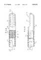
- FIG. 6is an enlarged side elevational view of the FIG. 1 inner tubular member broken away partially in central cross section.
- FIG. 7is an enlarged pictorial view of the hub of the FIG. 6 inner tubular member.
- FIG. 8is an enlarged view of the distal portion of the inner tubular member, taken from the top in FIG. 6, and showing the tip and, in central cross section, a fragment of the flexible tube of the inner tubular member.
- FIG. 9is a sectional view substantially taken on the line 9--9 of FIG. 8.
- FIG. 10is an enlarged fragment of the FIG. 9 tip and flexible tube shown axially exploded and immediately after formation of their respective annular flange and distal recess.
- FIG. 11is a view similar to FIG. 10 but showing a knurling tool and mandrel coacting with the tip annular flange to texture the outer periphery of the latter.
- FIG. 12is a view similar to FIG. 11 but showing the textured tip annular flange prior to telescoping in the inner tube distal recess.
- FIG. 13is an enlarged fragment of FIG. 9, showing the tip annular flange and flexible tube recess in completed telescoped joinder.
- a tool 10 (FIG. 1) embodying the inventionis adapted for chucking in a powered rotating surgical handpiece HP (FIG. 1) of any desired kind.
- a powered rotating surgical handpiece HPFIG. 1
- the FIG. 1 handpiece HPhas a housing H fixedly containing a suitable rotary drive motor means, indicated in broken lines at MM (for example electrically or fluid powered).
- the motor means MMhas a rotary output shaft SH extending forward therefrom and fixedly carrying at its front end a diametrally protruding drive pin DP (FIG. 1).
- the handpiece HPmay contain a suitable power source, such as electric batteries, in the example shown same is connectable to a suitable remote power source P, for example an electrical power source or a pressure gas source.
- a suitable remote power source Pfor example an electrical power source or a pressure gas source.
- the handpiece HPalso preferably includes a connection to a suitable suction source S.
- the tool 10comprises an outer tubular member 11 (FIG. 2) comprising a proximal hollow mounting hub 12.
- An elongate outer tube 13is fixedly telescoped in and extends coaxially forwardly from the hollow mounting hub 12.
- the outer tube 13includes a distal end portion 14.
- the outer tube 13is for example, a rigid, thin walled, constant diameter, circular cross section tube of stainless steel or equivalent material.
- the mounting hub 12is configured to be rearwardly insertable in, fixedly held by, and releasably movable forward from a chuck C on the forward end of the handpiece HP.
- the handpiece HPincludes means, not shown, manually actuable to thereby allow tool 10 to be pulled forwardly out of the handpiece chuck C after surgery, or during surgery when it is desired to substitute a different tool into driving relationship with the handpiece HP.
- a rotatably driven, elongate, inner tubular member 30extends coaxially and rotatably within the outer tubular member 11 (FIG. 1).
- the inner tubular member 30has a proximal end portion, defining a drive hub 31 (FIG. 6) rotatably drivably engagable by the handpiece rotary shaft SH and its transverse drive pin DP.
- the hub 31includes at least two (here four) diametrally opposed, evenly circumferentially distributed, rearward opening notches 32 circumferentially spaced by a corresponding number of rear extending fingers 33.
- the notches 32 and fingers 33surround and extend rearward from a central, blind, rear opening recess 34 in the hub 31.
- a coil compression spring 35(FIG. 1) is snugly housed in the recess 34 and extends rearward therefrom.
- the rotatable inner tubular member 30includes an inner tube 36 (FIG. 6) coaxially fixed to and extending forward from the drive hub 31.
- the inner tube 36is supported for rotation with the outer tube 13.
- the rotatable inner tubular member 30has a distal tissue working tip 40 fixed forward on the inner tube 36 for rotation therewith and snugly rotatably disposed within the distal end portion 14 of the outer tubular member 11.
- the distal end portion 14 and tip 40here have means, hereafter discussed more fully, for surgically working the tissue of a patient at a surgical site on the patient.
- Tools of the herein described typecan be provided with a variety of different purpose, surgical tissue working means, including burs, cutters, etc. of conventional type.
- the distal end portion 14 of the outer tubular member 11is provided with a laterally, and somewhat forwardly, opening window 41.
- the window 41has laterally opposed cutting edges.
- the window 41may be so formed by forming the distal end portion of the outer tubular member with a semi-spherical closed front end 43 and then machining away a part thereof, as here shown in FIG. 4.
- the inner tube tip 40is rotatable snugly within the outer distal end portion 14 and has a similar window 42 (FIGS. 6, 8 and 9), also with laterally opposed cutting edges rotatable in shearing relation past the cutting edges of the window 41.
- the inner tubular member 30is axially insertable forwardly into the outer tubular member 11 and is axially rearwardly removable therefrom when not installed on a handpiece HP.
- the forward end of the shaft SH of the handpiecepartly compresses the spring 35 (FIG.
- the diametral drive pin DP of the handpiece shaftenters and rides in a diametrally opposed pair of the notches 32 of the drive hub 31 and, upon rotation of the shaft SH, the drive pin DP corresponding rotates the inner tubular member 30 and thereby rotates the tissue working tip 40 thereof to rotationally move the cutting edges of its window 42 past the corresponding cutting edges of the outer tubular member window 41.
- the tool 10can be used for simultaneously cutting tissue at the surgical site and removing flowable material from the surgical site.
- the toolis conventional.
- One example of such a toolis shown in above referenced Cezana et al. U.S. Pat. No. 5,192,292, assigned to the Assignee of the present invention.
- the inner tube 36(FIG. 6) is bendable and is of flexible polymer material.
- such polymer materialis polyetheretherketone (PEEK).
- FIG. 6schematically illustrates at 36' the ability of the inner tube 36 to bend as it rotates, to conform with a surrounding angled portion 50 (FIG. 1) of the outer tube 13. While the present invention can be used with both straight and angled outer tubes 13, the ability of the inner tube 36 to bend while rotating provides special advantages enabling it to be used with bent or bendable, angled tubes of the kind shown at 50 in FIG. 1.
- the hollow interior of the tipextends from its cutting window 42 (FIG. 9) rearwardly through the annular flange 61 into communication with the bore 73 of the inner tube 36.
- the tip hollow interior and tube borehave substantially the same internal diameter and are coaxial to provide a substantially continuous interior wall along said tip and inner tube.
- the tip 40(FIGS. 8 and 9) has a reduced outside diameter, proximal end portion 60 defining a preferably cylindrical, annular flange 61 fixedly received within a preferably cylindrical, distal opening recess 62 of the inner tube 36 for fixing the tissue working tip 40 to the polymer inner tube 36.
- the wall thickness of the inner tube 36, around the recess 62is approximately two-thirds the wall thickness of the inner tube rearward of the recess 62, namely at its non-recessed inner peripheral wall 72.
- the ratio two-thirdsmay vary but preferably will be in the range of 60 to 75%.
- the annular flange 61is externally textured with hills 63 and valleys 64 (FIG. 13).
- the polymer material forming the inner wall of the inner tube 36 that defines recess 62is shaped to have complementary hills 65 that seat in the valley of annular flange 62.
- the interlocking of the inner tube hills 65 in the flange valleysprevent rotational and axial relative movement of the tissue working tip 40 with respect to the inner tube 36.
- the polymer material of the inner tube 36is flowed to form the hills 65 according to a method described hereinafter.
- the tissue working tip 40is of stainless steel and the external texture on the annular flange 61, with its hills 63 and valleys 64, is a knurled pattern 71 on the outer periphery of the tip annular flange.
- the knurled pattern 71extends substantially the circumference and length of the tip annular flange 61.
- the radial depth from hill top to valley bottomis approximately, or at least approaches two-thirds, the maximum wall thickness of the thus textured annular flange 61 (i.e.
- the minimum annular flange thickness from valley bottom radially inward to the inner peripheral wall 70 of the annular flange 61is about one-third the radial thickness from the peak of a hill 63 to such inner peripheral wall 70.
- the ratio two-thirdsmay vary but preferably will be in the range of 60 to 75%.
- the knurled pattern 71, defining the hills 63 and valleys 64,is somewhat schematically indicated in FIG. 8.
- the tip 40is fixed in the front end of the inner tube 36 as follows.
- the tip 40is formed as a generally bullet shaped hollow, rearward opening cup and the window 42 is machined in the forward portion of the tip.
- the rear peripheral portion of the tip 40is machined to reduce the outside diameter thereof and thereby form the annular flange 61 (FIG. 10).
- the forward end portion of the inner tube 36is machined at the inner peripheral wall 72 thereof to form the forward opening recess 62.
- the respective peripheral walls 74 and 76 of the annular flange 61 and recess 62are substantially cylindrical and thus each have a substantial constant diameter.
- the outside diameter of the tip annular flange 61is preferably slightly larger than the inside diameter of the recess 62 (for example about 0.010 inch in one unit constructed according to the invention, wherein the outside diameter of the outer tube 13 was about 4 mm).
- the resultis a small negative clearance indicated at NC in FIG. 10.
- the outer periphery 74 (FIG. 10) of the tip annular flange 61is externally textured by forming the hills 63 and valleys 64 (FIG. 11) therein. External texturing of the annular flange 61 is, in the preferred embodiment shown, accomplished by knurling. Because of the very small wall thickness of the annular flange 61 prior to knurling (0.0058 inch in one unit constructed according to the invention), a mandrel M (FIG. 11) is snugly but removably inserted within and radially supports the annular flange 61. Thereafter the tip 40 is rotated relative to a conventional knurling tool KT (FIG.
- the wall thickness of annular flange 61 at the hill peakswas about 0.0084 inch and at the valley bottoms was about 0.0032 inch, as compared to the original unknurled (as in FIG.
- peripheral flange wall thicknessof about 0.0058 inch.
- the tip 40is heated.
- the polymer inner tube 36is of material of a thermoplastic character.
- the heated temperature of the tip annular flange 61is sufficient to soften, and thus allow plastic flow of, the polymer material which bounds the perimeter of the inner tube recess 62 upon contact therewith.
- the tip 40 and tube 36are relatively moved coaxially to substantially fully insert the heated tip annular flange 61 in the tube recess 62 thereby causing the thermoplastic tube material bounding the recess 62 to flow around the hills 63 and into the valleys 64 of the heated annular flange 61 so as to form hills 65 (FIG. 13).
- the tip 40 and inner tube 36are then allowed to cool, thus substantially rigidifying the flowed thermoplastic material of the tube 36 around the hills 63 and in the valleys 64 of the annular flange 61 and therewith mechanically interlocking the tube 36 and tip 40 in axially and circumferentially fixed relation as seen in FIG. 13.
- this mechanical interlockingis aided, in fixing the tip 40 and tube 36 together, by applying a thin layer (schematically shown in dotted lines at 75 in FIG. 12) of a suitable adhesive, such as an epoxy adhesive, to the hills 63 and valleys 64 of the heated annular flange 61 prior to telescoping the annular flange 61 into the recess 62.
- a suitable adhesivesuch as an epoxy adhesive
- the adhesivecures shortly after the FIG. 13 telescoped insertion is completed.
- Use of adhesiveis optional, but such adhesive would desirably assist in compensating for recess and annular flange hill diameters that are respectively at the high and low ends of their respective clearance ranges and thus provide a looser than normal fit of annular flange 61 within recess 62.
- the annular flange 61is inserted in the tube recess 62 so as to leave an axial clearance gap G (FIG. 13) between the rear (left) end of the tip annular flange 61 and the opposed end face 80 the recess 62.
- this clearance gap Gwas about 0.015 inch.
- the clearance gap Gprovides a predictable break point far to the rear of the windows 41 and 42, and indeed to the rear of the entire tip 40.
- the clearance gap Gprovides a minimum strength point along the length of the inner tubular member.
- the torque capability of the inner tubular membermay be exceeded, causing it to circumferentially shear, and thus break into two pieces. Circumferential shear may occur by failure of the adhesive 75 (if any) and/or failure of the polymer material in the region of the tip hills 63 and valleys 64, thereby allowing the tip to rotate or even axially separate from the inner tube.
- the inner tube material at the clearance gap Gwill fail, in shear, allowing the entire tip 40, and the portion of the inner tube 36 surrounding it, to separate from the rearward portion of the inner tube 36, behind the gap G.
- the length of the separated front portion of the inner tubular member, namely the tip 40 as a whole, with or without surrounding material of the tubular member forward of the gap Gis too long to escape out of the window 41 of the outer tube 13 and hence cannot escape into the surgical site in the patient.
- a particular maximum torquee.g.
- the shear strength of the polymer inner tube 36 at the gap Gis substantially less than that of all parts of the stainless tip 40 despite the substantially smaller wall thicknesses of the stainless steel tip 40.
- the clearance gap Gthus assures a piece separated from the inner tube 36, to the front end thereof, will be at least as long as the tip 40 and that such shearing would be of the polymer material of the inner tube 36 at the clearance gap G rather than for example, at the stress riser where the annular flange 61 joins the thicker front portion of the tip 40.
- This constructionavoids problems present in certain prior art devices wherein the tip can be separated from its supporting inner tube in such a manner that it can easily be axially pulled away from the tube and wherein the tip itself is short enough to exit from the open front of the outer tube and fall into the surgical site.
- the maximum wall thickness of the polymer tubewas about 0.0202 inch whereas the wall thickness at the recess was about 0.0135 inch.
- the outside diameter of the tubewas about 0.1304 inch.
- the maximum wall thickness of the tipwas about 0.0181 inch and the outside diameter of the tip was about 0.1292 inch.
- the proximal end portion 89 of the inner tube 36(FIG. 6) is fixed within a forward opening central passage 90 of the drive hub 31 and extends partly into a diametral suction port 91 which extends transversely through the drive hub 31.
- the inside diameter of the hub passage 90was about 0.134 inch and the outside diameter of the unfinished inner tube 36 was about 0.132 inch, tolerances permitting a fit therebetween ranging from snug to interference.
- the rear portion 89 of the inner tube 36was textured, as by knurling, in the manner generally shown in FIG. 6. The knurling depth assures that the tops of the hills of the knurled portion 89 interfere somewhat with the peripheral wall of the drive hub passage 90 while the bottoms of the valleys of the knurled portion 89 are spaced from the interior peripheral wall of the drive hub passage 90.
- the inner tube rear end portion 89was coated with a thin layer of adhesive, preferably epoxy resin.
- adhesivepreferably epoxy resin.
- the drive hub 31is of molded plastics material, preferably polycarbonate in one unit constructed according to the invention. Using a polycarbonate drive hub 31 and a PEEK inner tube 36, an epoxy adhesive was found to be compatible with both materials and to provide a rigid bond therebetween.
- One unit constructed according to the inventionhereafter referred to as a 4 mm (millimeter) unit, utilized an outer tube 13 (FIG. 1) having an outside diameter of about 4 mm.
- an outer tube 13(FIG. 1) having an outside diameter of about 4 mm.
- the structure above describedhas been found to work well with tools in the 3.5 to 5.5 mm range. In tools below the 3.5 mm range, the inside diameter of the inner tube 36 is reduced enough that there may be risk of clogging during suction of fluent material from a surgical site, at least in some types of surgery.
- an outer tube 13 having an outside diameter exceeding 5 or 5.5 mmit may be difficult to maneuver the tool into a tight surgical site of the kind found in certain kinds of surgery. Accordingly, while the above described tool structure is useable in tools outside the range of 3.5 to 5.5 mm, that is a useful range (so as not to clog easily and yet penetrate tight surgical sites).
Landscapes
- Health & Medical Sciences (AREA)
- Surgery (AREA)
- Life Sciences & Earth Sciences (AREA)
- Biomedical Technology (AREA)
- Nuclear Medicine, Radiotherapy & Molecular Imaging (AREA)
- Engineering & Computer Science (AREA)
- Orthopedic Medicine & Surgery (AREA)
- Heart & Thoracic Surgery (AREA)
- Medical Informatics (AREA)
- Molecular Biology (AREA)
- Animal Behavior & Ethology (AREA)
- General Health & Medical Sciences (AREA)
- Public Health (AREA)
- Veterinary Medicine (AREA)
- Surgical Instruments (AREA)
Abstract
Description
Claims (18)
Priority Applications (1)
| Application Number | Priority Date | Filing Date | Title |
|---|---|---|---|
| US08/919,565US5961532A (en) | 1997-08-29 | 1997-08-29 | Surgical tool having flexible tubular inner member movable for tissue working |
Applications Claiming Priority (1)
| Application Number | Priority Date | Filing Date | Title |
|---|---|---|---|
| US08/919,565US5961532A (en) | 1997-08-29 | 1997-08-29 | Surgical tool having flexible tubular inner member movable for tissue working |
Publications (1)
| Publication Number | Publication Date |
|---|---|
| US5961532Atrue US5961532A (en) | 1999-10-05 |
Family
ID=25442319
Family Applications (1)
| Application Number | Title | Priority Date | Filing Date |
|---|---|---|---|
| US08/919,565Expired - LifetimeUS5961532A (en) | 1997-08-29 | 1997-08-29 | Surgical tool having flexible tubular inner member movable for tissue working |
Country Status (1)
| Country | Link |
|---|---|
| US (1) | US5961532A (en) |
Cited By (45)
| Publication number | Priority date | Publication date | Assignee | Title |
|---|---|---|---|---|
| US6280447B1 (en)* | 1998-12-23 | 2001-08-28 | Nuvasive, Inc. | Bony tissue resector |
| US6610059B1 (en) | 2002-02-25 | 2003-08-26 | Hs West Investments Llc | Endoscopic instruments and methods for improved bubble aspiration at a surgical site |
| US20030191488A1 (en)* | 2002-04-09 | 2003-10-09 | Braden Robison | Surgical instrument |
| US20030195490A1 (en)* | 2000-05-25 | 2003-10-16 | Cook Incorporated | Medical device including unitary, continuous portion of varying durometer |
| US6638289B1 (en)* | 2000-10-16 | 2003-10-28 | Stryker Corporation | Elongated endoscopic cutting accessories |
| US20040181250A1 (en)* | 2003-02-20 | 2004-09-16 | Adams Kenneth M | Surgical elongate blade assembly with interchangeable inner member, kit and method relating thereto |
| US20050033354A1 (en)* | 2001-11-19 | 2005-02-10 | Scimed Life Systems, Inc. | Endoscopic surgical instrument |
| US20050043739A1 (en)* | 2003-08-18 | 2005-02-24 | Sullivan Robert L. | Hybrid flexible drive shaft |
| US6921880B2 (en) | 2003-04-04 | 2005-07-26 | Constance F. Berger | Apparatus for heating bottles and method of manufacturing same |
| US20050251112A1 (en)* | 2003-05-23 | 2005-11-10 | Danitz David J | Articulating mechanism for remote manipulation of a surgical or diagnostic tool |
| US20050273085A1 (en)* | 2004-06-07 | 2005-12-08 | Novare Surgical Systems, Inc. | Articulating mechanism with flex-hinged links |
| US20060111209A1 (en)* | 2004-11-23 | 2006-05-25 | Novare Surgical Systems, Inc. | Articulating mechanisms and link systems with torque transmission in remote manipulation of instruments and tools |
| US20080021489A1 (en)* | 2004-01-21 | 2008-01-24 | Adams Kenneth M | Angled tissue cutting instrument having variably positionable cutting window and indexing tool for use therewith |
| US20080071303A1 (en)* | 2006-07-11 | 2008-03-20 | Randall Lee Hacker | Rotary shaver with improved connection between flexible and rigid rotatable tubes |
| US7785252B2 (en) | 2004-11-23 | 2010-08-31 | Novare Surgical Systems, Inc. | Articulating sheath for flexible instruments |
| US7828808B2 (en) | 2004-06-07 | 2010-11-09 | Novare Surgical Systems, Inc. | Link systems and articulation mechanisms for remote manipulation of surgical or diagnostic tools |
| US7862554B2 (en) | 2007-04-16 | 2011-01-04 | Intuitive Surgical Operations, Inc. | Articulating tool with improved tension member system |
| US20110077674A1 (en)* | 2007-04-06 | 2011-03-31 | Interlace Medical, Inc. | Tissue cutter with differential hardness |
| US20110087254A1 (en)* | 2009-10-09 | 2011-04-14 | Cardiovascular Systems, Inc. | Rotational atherectomy device with keyed exchangeable drive shaft |
| US20110166576A1 (en)* | 2005-11-29 | 2011-07-07 | Medtronic Xomed, Inc. | Method and apparatus for removing material from an intervertebral disc space, such as in performing a nucleotomy |
| US8025656B2 (en) | 2006-11-07 | 2011-09-27 | Hologic, Inc. | Methods, systems and devices for performing gynecological procedures |
| US8100824B2 (en) | 2003-05-23 | 2012-01-24 | Intuitive Surgical Operations, Inc. | Tool with articulation lock |
| US8182417B2 (en) | 2004-11-24 | 2012-05-22 | Intuitive Surgical Operations, Inc. | Articulating mechanism components and system for easy assembly and disassembly |
| US8409244B2 (en) | 2007-04-16 | 2013-04-02 | Intuitive Surgical Operations, Inc. | Tool with end effector force limiter |
| US8465475B2 (en) | 2008-08-18 | 2013-06-18 | Intuitive Surgical Operations, Inc. | Instrument with multiple articulation locks |
| US8528563B2 (en) | 2007-04-06 | 2013-09-10 | Hologic, Inc. | Systems, methods and devices for performing gynecological procedures |
| US8535347B2 (en) | 2003-05-23 | 2013-09-17 | Intuitive Surgical Operations, Inc. | Articulating mechanisms with bifurcating control |
| US8562640B2 (en) | 2007-04-16 | 2013-10-22 | Intuitive Surgical Operations, Inc. | Tool with multi-state ratcheted end effector |
| US8574253B2 (en) | 2007-04-06 | 2013-11-05 | Hologic, Inc. | Method, system and device for tissue removal |
| US8647349B2 (en) | 2006-10-18 | 2014-02-11 | Hologic, Inc. | Systems for performing gynecological procedures with mechanical distension |
| US20140324086A1 (en)* | 2013-03-25 | 2014-10-30 | Hanshi Llc | Endoscopic cutting instruments having improved efficiency and reduced manufacturing costs |
| US8951274B2 (en) | 2007-04-06 | 2015-02-10 | Hologic, Inc. | Methods of high rate, low profile tissue removal |
| US20150080896A1 (en) | 2013-07-19 | 2015-03-19 | Ouroboros Medical, Inc. | Anti-clogging device for a vacuum-assisted, tissue removal system |
| US9161771B2 (en) | 2011-05-13 | 2015-10-20 | Intuitive Surgical Operations Inc. | Medical instrument with snake wrist structure |
| US9221179B2 (en) | 2009-07-23 | 2015-12-29 | Intuitive Surgical Operations, Inc. | Articulating mechanism |
| US9358027B2 (en) | 2012-08-22 | 2016-06-07 | Wexler Surgical, Inc. | Thoracoscopic instrument |
| US9392935B2 (en) | 2006-11-07 | 2016-07-19 | Hologic, Inc. | Methods for performing a medical procedure |
| US9561045B2 (en) | 2006-06-13 | 2017-02-07 | Intuitive Surgical Operations, Inc. | Tool with rotation lock |
| US9603610B2 (en) | 2013-03-15 | 2017-03-28 | DePuy Synthes Products, Inc. | Tools and methods for tissue removal |
| US9687257B2 (en) | 2014-06-04 | 2017-06-27 | Zimmer Surgical, Inc. | Pin wire driver device |
| US10448967B2 (en) | 2011-12-03 | 2019-10-22 | DePuy Synthes Products, Inc. | Discectomy kits with an obturator, guard cannula |
| US11000305B2 (en) | 2017-08-02 | 2021-05-11 | Stryker Corporation | Surgical tool systems, and methods of use thereof |
| US20210196347A1 (en)* | 2018-05-21 | 2021-07-01 | Smith & Nephew, Inc. | Lumen reinforcement device and system |
| US11678893B2 (en) | 2017-02-10 | 2023-06-20 | Zimmer, Inc. | Systems for advancing a pin wire with a driver device |
| US11903602B2 (en) | 2009-04-29 | 2024-02-20 | Hologic, Inc. | Uterine fibroid tissue removal device |
Citations (10)
| Publication number | Priority date | Publication date | Assignee | Title |
|---|---|---|---|---|
| US4646738A (en)* | 1985-12-05 | 1987-03-03 | Concept, Inc. | Rotary surgical tool |
| US5152744A (en)* | 1990-02-07 | 1992-10-06 | Smith & Nephew Dyonics | Surgical instrument |
| US5285795A (en)* | 1991-09-12 | 1994-02-15 | Surgical Dynamics, Inc. | Percutaneous discectomy system having a bendable discectomy probe and a steerable cannula |
| US5286253A (en)* | 1992-10-09 | 1994-02-15 | Linvatec Corporation | Angled rotating surgical instrument |
| US5411514A (en)* | 1992-09-30 | 1995-05-02 | Linvatec Corporation | Bendable variable angle rotating shaver |
| US5437630A (en)* | 1993-10-27 | 1995-08-01 | Stryker Corporation | Arthroscopic cutter having curved rotatable drive |
| US5540708A (en)* | 1993-05-06 | 1996-07-30 | Linvatec Corporation | Polymeric rotatable shaver blade with interlocking cutting tip |
| US5620447A (en)* | 1993-01-29 | 1997-04-15 | Smith & Nephew Dyonics Inc. | Surgical instrument |
| US5643294A (en)* | 1993-03-01 | 1997-07-01 | United States Surgical Corporation | Surgical apparatus having an increased range of operability |
| US5643303A (en)* | 1993-01-26 | 1997-07-01 | Donahue; John R. | Flexible surgical instrument |
- 1997
- 1997-08-29USUS08/919,565patent/US5961532A/ennot_activeExpired - Lifetime
Patent Citations (13)
| Publication number | Priority date | Publication date | Assignee | Title |
|---|---|---|---|---|
| US4646738A (en)* | 1985-12-05 | 1987-03-03 | Concept, Inc. | Rotary surgical tool |
| US5152744A (en)* | 1990-02-07 | 1992-10-06 | Smith & Nephew Dyonics | Surgical instrument |
| US5322505A (en)* | 1990-02-07 | 1994-06-21 | Smith & Nephew Dyonics, Inc. | Surgical instrument |
| US5510070A (en)* | 1990-02-07 | 1996-04-23 | Smith & Nephew Dyonics, Inc. | Method of fabricating a surgical instrument |
| US5285795A (en)* | 1991-09-12 | 1994-02-15 | Surgical Dynamics, Inc. | Percutaneous discectomy system having a bendable discectomy probe and a steerable cannula |
| US5411514A (en)* | 1992-09-30 | 1995-05-02 | Linvatec Corporation | Bendable variable angle rotating shaver |
| US5286253A (en)* | 1992-10-09 | 1994-02-15 | Linvatec Corporation | Angled rotating surgical instrument |
| US5643303A (en)* | 1993-01-26 | 1997-07-01 | Donahue; John R. | Flexible surgical instrument |
| US5620447A (en)* | 1993-01-29 | 1997-04-15 | Smith & Nephew Dyonics Inc. | Surgical instrument |
| US5643294A (en)* | 1993-03-01 | 1997-07-01 | United States Surgical Corporation | Surgical apparatus having an increased range of operability |
| US5540708A (en)* | 1993-05-06 | 1996-07-30 | Linvatec Corporation | Polymeric rotatable shaver blade with interlocking cutting tip |
| US5766200A (en)* | 1993-05-06 | 1998-06-16 | Linvatec Corporation | Rotatable endoscopic shaver with polymeric blades |
| US5437630A (en)* | 1993-10-27 | 1995-08-01 | Stryker Corporation | Arthroscopic cutter having curved rotatable drive |
Cited By (101)
| Publication number | Priority date | Publication date | Assignee | Title |
|---|---|---|---|---|
| US6280447B1 (en)* | 1998-12-23 | 2001-08-28 | Nuvasive, Inc. | Bony tissue resector |
| US6881209B2 (en) | 2000-05-25 | 2005-04-19 | Cook Incorporated | Medical device including unitary, continuous portion of varying durometer |
| US20030195490A1 (en)* | 2000-05-25 | 2003-10-16 | Cook Incorporated | Medical device including unitary, continuous portion of varying durometer |
| US7722795B2 (en) | 2000-05-25 | 2010-05-25 | Cook Incorporated And Sabin Corporation | Medical device including unitary, continuous portion of varying durometer |
| US6638289B1 (en)* | 2000-10-16 | 2003-10-28 | Stryker Corporation | Elongated endoscopic cutting accessories |
| US20050033354A1 (en)* | 2001-11-19 | 2005-02-10 | Scimed Life Systems, Inc. | Endoscopic surgical instrument |
| US6610059B1 (en) | 2002-02-25 | 2003-08-26 | Hs West Investments Llc | Endoscopic instruments and methods for improved bubble aspiration at a surgical site |
| US20030191488A1 (en)* | 2002-04-09 | 2003-10-09 | Braden Robison | Surgical instrument |
| US7244263B2 (en)* | 2002-04-09 | 2007-07-17 | Stryker Corporation | Surgical instrument |
| US20040181250A1 (en)* | 2003-02-20 | 2004-09-16 | Adams Kenneth M | Surgical elongate blade assembly with interchangeable inner member, kit and method relating thereto |
| WO2004073531A3 (en)* | 2003-02-20 | 2004-11-25 | Sdgi Holdings Inc | Surgical elongate blade assembly with interchangeable inner member, kit and method relating thereto |
| US7455679B2 (en) | 2003-02-20 | 2008-11-25 | Medtronic Xomed, Inc. | Surgical elongate blade assembly with interchangeable inner member, kit and method relating thereto |
| US6921880B2 (en) | 2003-04-04 | 2005-07-26 | Constance F. Berger | Apparatus for heating bottles and method of manufacturing same |
| US8535347B2 (en) | 2003-05-23 | 2013-09-17 | Intuitive Surgical Operations, Inc. | Articulating mechanisms with bifurcating control |
| US20050251112A1 (en)* | 2003-05-23 | 2005-11-10 | Danitz David J | Articulating mechanism for remote manipulation of a surgical or diagnostic tool |
| US10722314B2 (en) | 2003-05-23 | 2020-07-28 | Intuitive Surgical Operations, Inc. | Articulating retractors |
| US8100824B2 (en) | 2003-05-23 | 2012-01-24 | Intuitive Surgical Operations, Inc. | Tool with articulation lock |
| US9434077B2 (en) | 2003-05-23 | 2016-09-06 | Intuitive Surgical Operations, Inc | Articulating catheters |
| US9085085B2 (en) | 2003-05-23 | 2015-07-21 | Intuitive Surgical Operations, Inc. | Articulating mechanisms with actuatable elements |
| US7615066B2 (en) | 2003-05-23 | 2009-11-10 | Novare Surgical Systems, Inc. | Articulating mechanism for remote manipulation of a surgical or diagnostic tool |
| US9072427B2 (en) | 2003-05-23 | 2015-07-07 | Intuitive Surgical Operations, Inc. | Tool with articulation lock |
| US7682307B2 (en) | 2003-05-23 | 2010-03-23 | Novare Surgical Systems, Inc. | Articulating mechanism for remote manipulation of a surgical or diagnostic tool |
| US9440364B2 (en) | 2003-05-23 | 2016-09-13 | Intuitive Surgical Operations, Inc. | Articulating instrument |
| US9737365B2 (en) | 2003-05-23 | 2017-08-22 | Intuitive Surgical Operations, Inc. | Tool with articulation lock |
| US9550300B2 (en) | 2003-05-23 | 2017-01-24 | Intuitive Surgical Operations, Inc. | Articulating retractors |
| US9498888B2 (en) | 2003-05-23 | 2016-11-22 | Intuitive Surgical Operations, Inc. | Articulating instrument |
| US9370868B2 (en) | 2003-05-23 | 2016-06-21 | Intuitive Surgical Operations, Inc. | Articulating endoscopes |
| US11547287B2 (en) | 2003-05-23 | 2023-01-10 | Intuitive Surgical Operations, Inc. | Surgical instrument |
| US10342626B2 (en) | 2003-05-23 | 2019-07-09 | Intuitive Surgical Operations, Inc. | Surgical instrument |
| US20050043739A1 (en)* | 2003-08-18 | 2005-02-24 | Sullivan Robert L. | Hybrid flexible drive shaft |
| US20060100631A1 (en)* | 2003-08-18 | 2006-05-11 | Symmetry Medical, Inc. | Hybrid flexible drive shaft |
| US8202288B2 (en)* | 2004-01-21 | 2012-06-19 | Medtronic Xomed, Inc. | Angled tissue cutting instrument having variably positionable cutting window and indexing tool for use therewith |
| US20080021489A1 (en)* | 2004-01-21 | 2008-01-24 | Adams Kenneth M | Angled tissue cutting instrument having variably positionable cutting window and indexing tool for use therewith |
| US9517326B2 (en) | 2004-06-07 | 2016-12-13 | Intuitive Surgical Operations, Inc. | Link systems and articulation mechanisms for remote manipulation of surgical or diagnostic tools |
| US7828808B2 (en) | 2004-06-07 | 2010-11-09 | Novare Surgical Systems, Inc. | Link systems and articulation mechanisms for remote manipulation of surgical or diagnostic tools |
| US8323297B2 (en) | 2004-06-07 | 2012-12-04 | Intuitive Surgical Operations, Inc. | Articulating mechanism with flex-hinged links |
| US11491310B2 (en) | 2004-06-07 | 2022-11-08 | Intuitive Surgical Operations, Inc. | Articulating mechanism with flex-hinged links |
| US8419747B2 (en) | 2004-06-07 | 2013-04-16 | Intuitive Surgical Operations, Inc. | Link systems and articulation mechanisms for remote manipulation of surgical or diagnostic tools |
| US10729885B2 (en) | 2004-06-07 | 2020-08-04 | Intuitive Surgical Operations, Inc. | Articulating mechanism with flex-hinged links |
| US20050273085A1 (en)* | 2004-06-07 | 2005-12-08 | Novare Surgical Systems, Inc. | Articulating mechanism with flex-hinged links |
| US9095253B2 (en) | 2004-06-07 | 2015-08-04 | Intuitive Surgical Operations, Inc. | Articulating mechanism with flex hinged links |
| US7678117B2 (en) | 2004-06-07 | 2010-03-16 | Novare Surgical Systems, Inc. | Articulating mechanism with flex-hinged links |
| US8920429B2 (en) | 2004-06-07 | 2014-12-30 | Intuitive Surgical Operations, Inc. | Link systems and articulation mechanisms for remote manipulation of surgical or diagnostic tools |
| US9861786B2 (en) | 2004-06-07 | 2018-01-09 | Intuitive Surgical Operations, Inc. | Articulating mechanism with flex hinged links |
| US7785252B2 (en) | 2004-11-23 | 2010-08-31 | Novare Surgical Systems, Inc. | Articulating sheath for flexible instruments |
| US9155449B2 (en) | 2004-11-23 | 2015-10-13 | Intuitive Surgical Operations Inc. | Instrument systems and methods of use |
| US20060111209A1 (en)* | 2004-11-23 | 2006-05-25 | Novare Surgical Systems, Inc. | Articulating mechanisms and link systems with torque transmission in remote manipulation of instruments and tools |
| US11638590B2 (en) | 2004-11-23 | 2023-05-02 | Intuitive Surgical Operations, Inc. | Articulating mechanisms and link systems with torque transmission in remote manipulation of instruments and tools |
| US10321927B2 (en) | 2004-11-23 | 2019-06-18 | Intuitive Surgical Operations, Inc. | Articulating mechanisms and link systems with torque transmission in remote manipulation of instruments and tools |
| US8277375B2 (en) | 2004-11-23 | 2012-10-02 | Intuitive Surgical Operations, Inc. | Flexible segment system |
| US9700334B2 (en) | 2004-11-23 | 2017-07-11 | Intuitive Surgical Operations, Inc. | Articulating mechanisms and link systems with torque transmission in remote manipulation of instruments and tools |
| US8182417B2 (en) | 2004-11-24 | 2012-05-22 | Intuitive Surgical Operations, Inc. | Articulating mechanism components and system for easy assembly and disassembly |
| US20110166576A1 (en)* | 2005-11-29 | 2011-07-07 | Medtronic Xomed, Inc. | Method and apparatus for removing material from an intervertebral disc space, such as in performing a nucleotomy |
| US9561045B2 (en) | 2006-06-13 | 2017-02-07 | Intuitive Surgical Operations, Inc. | Tool with rotation lock |
| US7993360B2 (en) | 2006-07-11 | 2011-08-09 | Arthrex, Inc. | Rotary shaver with improved connection between flexible and rigid rotatable tubes |
| US20080071303A1 (en)* | 2006-07-11 | 2008-03-20 | Randall Lee Hacker | Rotary shaver with improved connection between flexible and rigid rotatable tubes |
| US8840626B2 (en) | 2006-10-18 | 2014-09-23 | Hologic, Inc. | Systems for performing gynecological procedures with simultaneous tissue cutting and removal |
| US8840625B2 (en) | 2006-10-18 | 2014-09-23 | Hologic, Inc. | Systems for performing gynecological procedures with closed visualization lumen |
| US8834487B2 (en) | 2006-10-18 | 2014-09-16 | Hologic, Inc. | Systems and methods for preventing intravasation during intrauterine procedures |
| US8647349B2 (en) | 2006-10-18 | 2014-02-11 | Hologic, Inc. | Systems for performing gynecological procedures with mechanical distension |
| US8025656B2 (en) | 2006-11-07 | 2011-09-27 | Hologic, Inc. | Methods, systems and devices for performing gynecological procedures |
| US9392935B2 (en) | 2006-11-07 | 2016-07-19 | Hologic, Inc. | Methods for performing a medical procedure |
| US20110077674A1 (en)* | 2007-04-06 | 2011-03-31 | Interlace Medical, Inc. | Tissue cutter with differential hardness |
| US8574253B2 (en) | 2007-04-06 | 2013-11-05 | Hologic, Inc. | Method, system and device for tissue removal |
| US9339288B2 (en) | 2007-04-06 | 2016-05-17 | Hologic, Inc. | Uterine fibroid tissue removal device |
| US9301770B2 (en) | 2007-04-06 | 2016-04-05 | Hologic, Inc. | Systems, methods and devices for performing gynecological procedures |
| US9259233B2 (en) | 2007-04-06 | 2016-02-16 | Hologic, Inc. | Method and device for distending a gynecological cavity |
| US8528563B2 (en) | 2007-04-06 | 2013-09-10 | Hologic, Inc. | Systems, methods and devices for performing gynecological procedures |
| US11045217B2 (en) | 2007-04-06 | 2021-06-29 | Hologic, Inc. | Uterine fibroid tissue removal device |
| US8951274B2 (en) | 2007-04-06 | 2015-02-10 | Hologic, Inc. | Methods of high rate, low profile tissue removal |
| US9539019B2 (en) | 2007-04-06 | 2017-01-10 | Hologic, Inc. | Uterine fibroid tissue removal device |
| US9095366B2 (en) | 2007-04-06 | 2015-08-04 | Hologic, Inc. | Tissue cutter with differential hardness |
| US10130389B2 (en) | 2007-04-06 | 2018-11-20 | Hologic, Inc. | Uterine fibroid tissue removal device |
| US7862554B2 (en) | 2007-04-16 | 2011-01-04 | Intuitive Surgical Operations, Inc. | Articulating tool with improved tension member system |
| US8562640B2 (en) | 2007-04-16 | 2013-10-22 | Intuitive Surgical Operations, Inc. | Tool with multi-state ratcheted end effector |
| US8409244B2 (en) | 2007-04-16 | 2013-04-02 | Intuitive Surgical Operations, Inc. | Tool with end effector force limiter |
| US11234694B2 (en) | 2008-08-18 | 2022-02-01 | Intuitive Surgical Operations, Inc. | Instrument with multiple articulation locks |
| US9737298B2 (en) | 2008-08-18 | 2017-08-22 | Intuitive Surgical Operations, Inc. | Instrument with articulation lock |
| US9033960B2 (en) | 2008-08-18 | 2015-05-19 | Intuitive Surgical Operations, Inc. | Instrument with multiple articulation locks |
| US8465475B2 (en) | 2008-08-18 | 2013-06-18 | Intuitive Surgical Operations, Inc. | Instrument with multiple articulation locks |
| US11998195B2 (en) | 2008-08-18 | 2024-06-04 | Intuitive Surgical Operations, Inc. | Instrument with multiple articulation locks |
| US11903602B2 (en) | 2009-04-29 | 2024-02-20 | Hologic, Inc. | Uterine fibroid tissue removal device |
| US9221179B2 (en) | 2009-07-23 | 2015-12-29 | Intuitive Surgical Operations, Inc. | Articulating mechanism |
| US20110087254A1 (en)* | 2009-10-09 | 2011-04-14 | Cardiovascular Systems, Inc. | Rotational atherectomy device with keyed exchangeable drive shaft |
| US10335177B2 (en) | 2011-05-13 | 2019-07-02 | Intuitive Surgical Operations, Inc. | Medical instrument with snake wrist structure |
| US9161771B2 (en) | 2011-05-13 | 2015-10-20 | Intuitive Surgical Operations Inc. | Medical instrument with snake wrist structure |
| US11357526B2 (en) | 2011-05-13 | 2022-06-14 | Intuitive Surgical Operations, Inc. | Medical instrument with snake wrist structure |
| US10448967B2 (en) | 2011-12-03 | 2019-10-22 | DePuy Synthes Products, Inc. | Discectomy kits with an obturator, guard cannula |
| US9358027B2 (en) | 2012-08-22 | 2016-06-07 | Wexler Surgical, Inc. | Thoracoscopic instrument |
| US11534194B2 (en) | 2013-03-15 | 2022-12-27 | DePuy Synthes Products, Inc. | Tools and methods for tissue removal |
| US9603610B2 (en) | 2013-03-15 | 2017-03-28 | DePuy Synthes Products, Inc. | Tools and methods for tissue removal |
| US10582943B2 (en) | 2013-03-15 | 2020-03-10 | Depuy Synthes Products Llc | Tools and methods for tissue removal |
| US9486232B2 (en)* | 2013-03-25 | 2016-11-08 | Hanshi Llc | Endoscopic cutting instruments having improved efficiency and reduced manufacturing costs |
| US20140324086A1 (en)* | 2013-03-25 | 2014-10-30 | Hanshi Llc | Endoscopic cutting instruments having improved efficiency and reduced manufacturing costs |
| US20150080896A1 (en) | 2013-07-19 | 2015-03-19 | Ouroboros Medical, Inc. | Anti-clogging device for a vacuum-assisted, tissue removal system |
| US10342563B2 (en) | 2013-07-19 | 2019-07-09 | DePuy Synthes Products, Inc. | Anti-clogging device for a vacuum-assisted, tissue removal system |
| US9687257B2 (en) | 2014-06-04 | 2017-06-27 | Zimmer Surgical, Inc. | Pin wire driver device |
| US11678893B2 (en) | 2017-02-10 | 2023-06-20 | Zimmer, Inc. | Systems for advancing a pin wire with a driver device |
| US11000305B2 (en) | 2017-08-02 | 2021-05-11 | Stryker Corporation | Surgical tool systems, and methods of use thereof |
| US12127758B2 (en) | 2017-08-02 | 2024-10-29 | Stryker Corporation | Surgical tool systems, and methods of use thereof |
| US20210196347A1 (en)* | 2018-05-21 | 2021-07-01 | Smith & Nephew, Inc. | Lumen reinforcement device and system |
Similar Documents
| Publication | Publication Date | Title |
|---|---|---|
| US5961532A (en) | Surgical tool having flexible tubular inner member movable for tissue working | |
| US5851208A (en) | Rotatable surgical burr | |
| US6238405B1 (en) | Percutaneous material removal device and method | |
| US5540708A (en) | Polymeric rotatable shaver blade with interlocking cutting tip | |
| US5437630A (en) | Arthroscopic cutter having curved rotatable drive | |
| AU674993B2 (en) | Surgical device | |
| US8202288B2 (en) | Angled tissue cutting instrument having variably positionable cutting window and indexing tool for use therewith | |
| EP1253863B1 (en) | Rotary bur instruments having bur tips with aspiration passages | |
| US5709698A (en) | Irrigating/aspirating shaver blade assembly | |
| AU722524B2 (en) | Surgical instrument | |
| US5690660A (en) | Arthroscopic cutter having curved rotatable drive | |
| AU2002329752B2 (en) | Flexible inner tubular member and rotary tissue cutting instrument having flexible inner tubular member | |
| US11701137B2 (en) | Reusable blade hub assembly | |
| US20090270899A1 (en) | Surgical tool system | |
| US20120221035A1 (en) | Surgical cutting accessory with flexible tube | |
| EP0796064A1 (en) | Hollow surgical cutter with apertured flutes | |
| US7244263B2 (en) | Surgical instrument | |
| EP0669105B1 (en) | Endoscopic resection instrument | |
| WO1992008416A1 (en) | Surgical instrument for material removal | |
| WO2023076579A1 (en) | Surgical device system |
Legal Events
| Date | Code | Title | Description |
|---|---|---|---|
| AS | Assignment | Owner name:STRYKER CORPORATION, MICHIGAN Free format text:ASSIGNMENT OF ASSIGNORS INTEREST;ASSIGNORS:FINLEY, MARSHAL E.;KAUKER, BARRY J.;CURRAN, MATTHEW J.;AND OTHERS;REEL/FRAME:008930/0137;SIGNING DATES FROM 19970915 TO 19970917 | |
| AS | Assignment | Owner name:BANK OF AMERICA NATIONAL TRUST AND SAVINGS ASSOCIA Free format text:SECURITY INTEREST;ASSIGNORS:STRYKER CORPORATION;STRYKER FAR EAST, INC.;STRYKER INTERNATIONAL INC.;AND OTHERS;REEL/FRAME:009817/0001 Effective date:19981204 Owner name:BANK OF AMERICA NATIONAL TRUST AND SAVINGS ASSOCIA Free format text:SECURITY AGREEMENT;ASSIGNORS:STRYKER CORPORATION;STRYKER FAR EAST, INC.;REEL/FRAME:014137/0212 Effective date:19981204 | |
| STCF | Information on status: patent grant | Free format text:PATENTED CASE | |
| CC | Certificate of correction | ||
| AS | Assignment | Owner name:STRYKER CORPORATION, MICHIGAN Free format text:RELEASE OF SECURITY INTEREST;ASSIGNOR:BANK OF AMERICA, N.A. (F/K/A BANK OF AMERICA NATIONAL TRUST AND SAVINGS ASSOCIATION);REEL/FRAME:012539/0557 Effective date:20020124 Owner name:STRYKER FAR EAST, INC., MICHIGAN Free format text:RELEASE OF SECURITY INTEREST;ASSIGNOR:BANK OF AMERICA, N.A. (F/K/A BANK OF AMERICA NATIONAL TRUST AND SAVINGS ASSOCIATION);REEL/FRAME:012539/0557 Effective date:20020124 Owner name:STRYKER INTERNATIONAL, INC., MICHIGAN Free format text:RELEASE OF SECURITY INTEREST;ASSIGNOR:BANK OF AMERICA, N.A. (F/K/A BANK OF AMERICA NATIONAL TRUST AND SAVINGS ASSOCIATION);REEL/FRAME:012539/0557 Effective date:20020124 Owner name:HOWMEDICA OSTEONICS CORPORATION, MICHIGAN Free format text:RELEASE OF SECURITY INTEREST;ASSIGNOR:BANK OF AMERICA, N.A. (F/K/A BANK OF AMERICA NATIONAL TRUST AND SAVINGS ASSOCIATION);REEL/FRAME:012539/0557 Effective date:20020124 Owner name:PHYSIOTHERAPY ASSOCIATES, INC., MICHIGAN Free format text:RELEASE OF SECURITY INTEREST;ASSIGNOR:BANK OF AMERICA, N.A. (F/K/A BANK OF AMERICA NATIONAL TRUST AND SAVINGS ASSOCIATION);REEL/FRAME:012539/0557 Effective date:20020124 Owner name:STRYKER PUERTO RICO INC., MICHIGAN Free format text:RELEASE OF SECURITY INTEREST;ASSIGNOR:BANK OF AMERICA, N.A. (F/K/A BANK OF AMERICA NATIONAL TRUST AND SAVINGS ASSOCIATION);REEL/FRAME:012539/0557 Effective date:20020124 Owner name:STRYKER SALES CORPORATION, MICHIGAN Free format text:RELEASE OF SECURITY INTEREST;ASSIGNOR:BANK OF AMERICA, N.A. (F/K/A BANK OF AMERICA NATIONAL TRUST AND SAVINGS ASSOCIATION);REEL/FRAME:012539/0557 Effective date:20020124 Owner name:STRYKER TECHNOLOGIES CORPORATION, MICHIGAN Free format text:RELEASE OF SECURITY INTEREST;ASSIGNOR:BANK OF AMERICA, N.A. (F/K/A BANK OF AMERICA NATIONAL TRUST AND SAVINGS ASSOCIATION);REEL/FRAME:012539/0557 Effective date:20020124 Owner name:STRYKER FOREIGN HOLDCO, INC., MICHIGAN Free format text:RELEASE OF SECURITY INTEREST;ASSIGNOR:BANK OF AMERICA, N.A. (F/K/A BANK OF AMERICA NATIONAL TRUST AND SAVINGS ASSOCIATION);REEL/FRAME:012539/0557 Effective date:20020124 Owner name:SMD CORPORATION, MICHIGAN Free format text:RELEASE OF SECURITY INTEREST;ASSIGNOR:BANK OF AMERICA, N.A. (F/K/A BANK OF AMERICA NATIONAL TRUST AND SAVINGS ASSOCIATION);REEL/FRAME:012539/0557 Effective date:20020124 Owner name:HOWMEDICAL LEIBINGER, INC., MICHIGAN Free format text:RELEASE OF SECURITY INTEREST;ASSIGNOR:BANK OF AMERICA, N.A. (F/K/A BANK OF AMERICA NATIONAL TRUST AND SAVINGS ASSOCIATION);REEL/FRAME:012539/0557 Effective date:20020124 | |
| FPAY | Fee payment | Year of fee payment:4 | |
| FPAY | Fee payment | Year of fee payment:8 | |
| FPAY | Fee payment | Year of fee payment:12 |