US5961134A - Apparatus for housing and transporting, and furnishing an adjustable user-platform for a portable computer - Google Patents
Apparatus for housing and transporting, and furnishing an adjustable user-platform for a portable computerDownload PDFInfo
- Publication number
- US5961134A US5961134AUS08/819,701US81970197AUS5961134AUS 5961134 AUS5961134 AUS 5961134AUS 81970197 AUS81970197 AUS 81970197AUS 5961134 AUS5961134 AUS 5961134A
- Authority
- US
- United States
- Prior art keywords
- base portion
- tray
- handle
- transport member
- portable computer
- Prior art date
- Legal status (The legal status is an assumption and is not a legal conclusion. Google has not performed a legal analysis and makes no representation as to the accuracy of the status listed.)
- Expired - Lifetime
Links
Images


Classifications
- A—HUMAN NECESSITIES
- A45—HAND OR TRAVELLING ARTICLES
- A45C—PURSES; LUGGAGE; HAND CARRIED BAGS
- A45C5/00—Rigid or semi-rigid luggage
- A45C5/14—Rigid or semi-rigid luggage with built-in rolling means
- G—PHYSICS
- G06—COMPUTING OR CALCULATING; COUNTING
- G06F—ELECTRIC DIGITAL DATA PROCESSING
- G06F1/00—Details not covered by groups G06F3/00 - G06F13/00 and G06F21/00
- G06F1/16—Constructional details or arrangements
- G06F1/1613—Constructional details or arrangements for portable computers
- G06F1/1628—Enclosures for carrying portable computers with peripheral devices, e.g. cases for a laptop and a printer
Definitions
- the present inventionrelates generally to luggage, and more particularly to an apparatus for transporting a computer that is convertible to an adjustable, stationary stand.
- the operating time allotted by the duration of the computer battery poweris limited. Many circumstances, such as waiting in an airport, call for an extended period of computer usage that goes beyond the time that a battery can commonly provide. Therefore, for extended usage, the portable computer may require an additional power supply.
- the present inventionis directed to overcoming, or at least reducing the effects of, one or more of the problems set forth above.
- a portable computer workstationis comprised of a base portion, a wheel system attached to the base portion, and a transport member having a first and second end portions.
- the first end portion of the transport memberhas a handle formed upon it.
- the second end portion of the transport memberis coupled to the base portion.
- the transport memberis movable between a first and a second position. The first position is where the handle of the transport member is adjacent to the base portion. The second position is where the handle of the transport member is spaced apart from the base portion.
- a trayis connected to the transport member such that the tray can move up and down the transport member.
- the trayis adapted to receive and secure a portable computer on the tray.
- the traycan be adjusted to be positioned where it is secured in the base portion or where it is secured at the top of the transport member, adjacent to the handle on the transport member.
- a portable containeris comprised of a base portion, a first wheel system, a second wheel system, and a transport member.
- the base portionhas a plurality of walls arranged to form at least one enclosed compartment, and at least one of the walls is moveable to provide access to the interior of the compartment.
- the first wheel systemis attached to the base portion adjacent to a first end portion.
- the first wheel systemis disposed to permit rolling movement of the base portion in a first direction.
- the second wheel systemis attached to the base portion adjacent the first end portion.
- the second wheel systemis disposed to permit rolling movement of the base portion in a second direction.
- the transport memberhas both, a first end and a second end portion.
- the first end portionhas a handle formed upon it.
- the second end portionis coupled to the base portion.
- the transport memberis moveable between a first and second position where the handle is adjacent the base portion in the first position.
- the handleis spaced from the base portion in the second position the base portion in the second position.
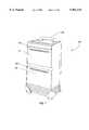
- FIG. 1illustrates an isometric front and side view of a suitcase in an upright position.
- FIG. 2illustrates an isometric front and side view the suitcase with its compartments opened
- FIG. 3illustrates an isometric rear side view of the suitcase
- FIG. 4illustrates the isometric view of the rear side of the suitcase with an extensible transport member shown in a expanded position
- FIG. 5illustrates a partial isometric front and side view of the suitcase with a pair of side wheels arranged to provide an alternate means of rolling the suitcase;
- FIG. 6illustrates an isometric rear and side view of the suitcase with the top compartment shown in an opened configuration
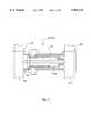
- FIG. 7illustrates a cross-sectional view of the cylindrical locks that are used to lock the extensible transport member and the computer tray in a desired position.
- FIG. 8illustrates an isometric rear and side view of the suitcase with a portable computer attached to a tray slideably arranged on the extensible transport member;
- FIG. 9illustrates an isometric rear and side view of the suitcase with the portable computer and tray located in an upright position
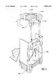
- FIG. 10illustrates an isometric rear and side view of the suitcase with an additional support member deployed
- FIG. 11illustrates an isometric rear and side view of the suitcase with the tray flaps deployed.
- the suitcase 100includes a plurality of walls arranged to form an enclosed upper compartment 110 and an enclosed lower compartment 120.
- the upper compartment 110is specially equipped to house a portable computer (not shown in FIG. 1).
- the lower compartment 120is available for general luggage.
- the upper and lower compartments 110, 120can be opened by using the upper and lower handles 130, 140, respectively.
- the suitcase 100also contains an extensible transport member 150 that is shown completely retracted into the suitcase 100, but can be extended and used as a handle during rolling movement of the suitcase 100.
- FIG. 2illustrates the suitcase 100 with a top compartment-cover 210 and a bottom compartment-cover 220.
- the compartments 110, 120can be accessed separately.
- the compartment-covers 210, 220are shown in an open position.
- a compartment restraint 230prevents the compartment-cover 210 from falling below an adjustable set point.
- the top compartment-cover 210is shaped differently from the bottom compartment 220.
- the bottom compartment-cover 220is rectangular in shape.
- the top compartment-cover 210consists of a side wall 240 and a top portion 250, with two notches 260 formed therein. The purpose of the notches 260 is to accommodate the extensible transport member 150.
- FIG. 3A rear side 300 of the suitcase 100 is shown in FIG. 3.
- the rear side 300 of the suitcase 100a locking mechanism 310 for the extensible transport member 150.
- the locking mechanism 310is pivotably engageable with the extensible transport member 150 so that the support 150 can be locked in an extended position.
- the rear side 300 of the suitcase 100also contains support members 330.
- the support members 330, 360are used for stabilization when the suitcase 100 is transformed into a computer workstation.
- FIG. 3also illustrates a footrest 340, which is connected to the support members 330, 360.
- the footrest 340 and the support members 330are operably connected together and deployable by pivotal movement of the footrest 340 to provide an extended, stabilized, and comfortable base during operation of the portable computer. That is, the suitcase 100 has a footprint of a first pre-selected size when the support members 330, 360 are retracted and a second larger size when the support members 330, 360 are extended.
- a pair of rear wheels 350 of the suitcase 100are shown positioned adjacent a lower portion 370 of the rear side 300. The rear wheels 350 facilitate movement of the suitcase 100 by tipping a top portion 370 of the suitcase 100 in a direction toward the rear side 300 so that the suitcase 100 is primarily supported by the wheels 350.
- the interaction between the elements of FIG. 3is describe in further detail below.
- the suitcase 100is preferably transported using the configuration shown in FIG. 4.
- the support 150is extended from its retracted position to a preferred height by pulling the support 150 in a direction generally away from the suitcase 100.
- the extensible transport member 150is then locked into place by the locking mechanism 310.
- the suitcase 100can be rolled on the wheels 350 by tilting the suitcase 100 backwards and pulling on the extensible transport member 150.
- the suitcase 100can also be rolled from a second position by using the configuration shown in FIG. 5.
- a pair of wheels 510are rollably coupled to a side 520 of the suitcase 100.
- the suitcase 100is two-way rollable. Being two-way rollable is particularly advantageous in situations where a pathway is constrained, such as in the aisle of an airplane. Since the side dimensions of the suitcase 100 is substantially smaller than the front and rear dimensions, the suitcase 100 can be rolled down a relatively narrow aisle using the side rollers 510.
- the suitcase 100can be converted into a computer workstation.
- the extensible transport member 150is retracted upwards.
- the top compartment-cover 210is opened as shown in FIG. 6. At this point the portable computer, which is stored in the suitcase 100, can be brought out.
- FIG. 6also illustrates several locking mechanisms for converting the suitcase 100 into a computer workstation.
- the unlocking of the locking mechanism 310 for the extensible transport member 150allows the member 150 to be moved from its initially retracted or its maximum extended position.
- the extensible member cylinder lock 610is used to lock the extensible transport member 150 in place at any desired height between its initially retracted position and its maximum extended position.
- the computer tray cylinder lock 630is used to lock the computer tray 810 into place once it is deployed (discussed in detail below).
- the cylinder locks 610, 630are engaged and disengaged by manipulating the cylinder lock tabs 620, 640 that are attached on the cylinder locks 610, 630.
- FIG. 7illustrates a cross-section view of the cylinder locks 610, 620.
- the locks 610, 620include a first and second housing 705, 706 coupled together at a threaded joint 710. Each housing 705, 706 extends over and captures within its end portions 720, 730 one of a pair of separated tubes 711, 712 that form the transport member 150.
- a pin 740extends through the housings 705, 706 and into contact with the outer walls of the tubes 711, 712. The action of turning the cylinder lock tabs 620, 640 rotates the threaded joints 710 causing the ends 720, 730 to move towards each other.
- the tubes 711, 712are pulled toward one another against the pin 740, creating a friction force on the tubes 711, 712, which results in the locking of the extensible transport member 150 or the computer tray 810. Once the extensible transport member 150 is adjusted to a desired height, the computer tray 810 is ready to be deployed.
- FIG. 8illustrates a tray 810 upon which a portable computer 820 is fastened.
- the tray 810is slidably attached to the extensible transport member 150, and can be moved along the extensible transport member 150.
- the tray 810is connected to the extensible transport member 150 by the pivoting arms 830. Once the tray 810 is locked into place near the top of the extensible transport member 150, it can be positioned into an upright position, as shown in FIG. 9. This is done by swiveling the pivoting arms 830 upwards until the tray 810 is upright and locked into place.
- the portable computer 820is fastened to the tray 810 with the fastening belts 910, which are readily connectable via a conventional coupling, such as buckles, hookless fasteners, elastic belts with hooks, etc.
- FIG. 10shows the suitcase 100 in a stabilized position. Once the tray 810 and the computer 820 are secured into an upright position, a base portion 1010 of the suitcase 100 should be stabilized.
- the base portion 1010is stabilized by the support members 330, 360.
- the support members 330, 360can be pulled out from their storage location and positioned such that the suitcase 100 is stabilized. Referring back to FIG. 9, the support members 330, 360 are shown retracted into a storage location.
- the support members 330, 360effectively expand the support provided by the base portion 1010. Essentially, the area of support at the bottom of the base portion 1010 is expanded due to the support members 330, 360.
- the support members 330, 360are generally rod shaped, having a free end portion 1016 and a pivotal end portion 1015.
- the pivotal end portion 1015captures the support members 330, 360 against the base 1010 but still allow the free end portion 1016 to be swung outwardly and engage the floor at a distance spaced from the base 1010.
- the base portion 1010also houses a footrest 340 that can be pulled out.
- the footrest 340swivels outwards such that a user can place a foot upon it while using the computer 820.
- the footrest 340is connected to the support members 330, 360 by two struts 1020 which have foldable elbows 1030. Therefore, part of the force exerted by the user's foot being placed upon the footrest 340 is transferred onto the support members 330, 360 via the struts 1020.
- the entire suitcase/workstation 100is stable when the computer 820 is deployed and the user is using the computer 820.
- the computer 820can be unfastened by unlocking the fastening belts 910.
- the platforms 1110pivot out from within the tray 810.
- the platforms 1110are swiveled out by pulling on the tabs 1120 on the edge of the platforms 1110.
- the platforms 1110can be used for various computer peripherals, such as a mouse 1160, or for miscellaneous items such as paperwork.
- the base portion 1010also houses the devices which hold a power extension cord 1130 and a phone line extension cord 1140. These wires are retractable and are pulled out in order to adapt to the length that the user needs.
- a power adapter wire 1150 from the computercan be connected to one end of the power extension cord 1130.
- one end of the phone line extension cordcan be connected to the phone jack on the computer 820. At this point the suitcase 100 is transformed into a fully functional computer workstation.
Landscapes
- Engineering & Computer Science (AREA)
- Theoretical Computer Science (AREA)
- Computer Hardware Design (AREA)
- Human Computer Interaction (AREA)
- Physics & Mathematics (AREA)
- General Engineering & Computer Science (AREA)
- General Physics & Mathematics (AREA)
- Purses, Travelling Bags, Baskets, Or Suitcases (AREA)
Abstract
Description
1. Field of the Invention
The present invention relates generally to luggage, and more particularly to an apparatus for transporting a computer that is convertible to an adjustable, stationary stand.
2. Description of the Related Art
By virtue of advancing computer technology, portable computer usage has steadily increased and is now in the mainstream among computer users. Today's portable computers not only feature CPUs that are as powerful as the ones in desktop computers, but they also offer the same or equivalent input/output peripherals such as hard drives, modems, and CD-ROM drives. Due to the proliferation of portable computers, computer users now carry their computers virtually everywhere.
The freedom that portable computers provide also brings with it the need for ergonomic devices for carrying and using portable computers in remote locations. There are many types of office furniture available that are ergonomically designed for desktop computer usage, such as adjustable keyboard platforms, but the prior art does not offer such devices for portable computers. The prior art only provides a means of carrying portable computers. Even though comfortably carrying a computer is essential, computer users still need an ergonomic tool to actually use the portable computer in remote locations. To date, the prior art fails to provide computer users with a convenient platform on which to use the portable computer in removed settings.
Furthermore, the operating time allotted by the duration of the computer battery power is limited. Many circumstances, such as waiting in an airport, call for an extended period of computer usage that goes beyond the time that a battery can commonly provide. Therefore, for extended usage, the portable computer may require an additional power supply.
It is now routine for portable computers to be configured with telecommunication capabilities. Typically, telecommunications occur through a modem and telephone line. However, the prior art has not provided a convenient and easy-to-use connection between the modem and telephone line. The prior art does not offer a product that facilitates a comfortable means of transporting a portable computer, while also providing a stand that will independently support the computer at a proper height for use while standing or sitting, and allow for convenient power and modem access.
The present invention is directed to overcoming, or at least reducing the effects of, one or more of the problems set forth above.
In accordance with one aspect of the present invention, there is provided a portable computer workstation. The portable computer workstation is comprised of a base portion, a wheel system attached to the base portion, and a transport member having a first and second end portions. The first end portion of the transport member has a handle formed upon it. The second end portion of the transport member is coupled to the base portion. The transport member is movable between a first and a second position. The first position is where the handle of the transport member is adjacent to the base portion. The second position is where the handle of the transport member is spaced apart from the base portion. A tray is connected to the transport member such that the tray can move up and down the transport member. The tray is adapted to receive and secure a portable computer on the tray. The tray can be adjusted to be positioned where it is secured in the base portion or where it is secured at the top of the transport member, adjacent to the handle on the transport member.
In accordance with another aspect of the present invention, there is provided a portable container. The portable container is comprised of a base portion, a first wheel system, a second wheel system, and a transport member. The base portion has a plurality of walls arranged to form at least one enclosed compartment, and at least one of the walls is moveable to provide access to the interior of the compartment. The first wheel system is attached to the base portion adjacent to a first end portion. The first wheel system is disposed to permit rolling movement of the base portion in a first direction. The second wheel system is attached to the base portion adjacent the first end portion. The second wheel system is disposed to permit rolling movement of the base portion in a second direction. The transport member has both, a first end and a second end portion. The first end portion has a handle formed upon it. The second end portion is coupled to the base portion. The transport member is moveable between a first and second position where the handle is adjacent the base portion in the first position. The handle is spaced from the base portion in the second position the base portion in the second position.
The foregoing and other advantages of the invention will become apparent upon reading the following detailed description and upon reference to the drawings in which:
FIG. 1 illustrates an isometric front and side view of a suitcase in an upright position.
FIG. 2 illustrates an isometric front and side view the suitcase with its compartments opened;
FIG. 3 illustrates an isometric rear side view of the suitcase;
FIG. 4 illustrates the isometric view of the rear side of the suitcase with an extensible transport member shown in a expanded position;
FIG. 5 illustrates a partial isometric front and side view of the suitcase with a pair of side wheels arranged to provide an alternate means of rolling the suitcase;
FIG. 6 illustrates an isometric rear and side view of the suitcase with the top compartment shown in an opened configuration;
FIG. 7 illustrates a cross-sectional view of the cylindrical locks that are used to lock the extensible transport member and the computer tray in a desired position.
FIG. 8 illustrates an isometric rear and side view of the suitcase with a portable computer attached to a tray slideably arranged on the extensible transport member;
FIG. 9 illustrates an isometric rear and side view of the suitcase with the portable computer and tray located in an upright position;
FIG. 10 illustrates an isometric rear and side view of the suitcase with an additional support member deployed; and
FIG. 11 illustrates an isometric rear and side view of the suitcase with the tray flaps deployed.
While the invention is susceptible to various modifications and alternative forms, specific embodiments have been shown by way of example in the drawings and will be described in detail herein. However, it should be understood that the invention is not intended to be limited to the particular forms disclosed. Rather, the intention is to cover all modifications, equivalents and alternatives falling within the spirit and scope of the invention as defined by the appended claims.
Illustrative embodiments of the invention are described below as they might be employed in the use of a suitcase that can be transformed into a computer workstation. In the interest of clarity, not all features of an actual implementation are described in this specification. It will of course be appreciated that in the development of any such actual embodiment, numerous implementation-specific decisions must be made to achieve the developers' specific goals, such as compliance with system-related and business-related constraints, which will vary from one implementation to another. Moreover, it will be appreciated that such a development effort might be complex and time-consuming, but would nevertheless be a routine undertaking for those of ordinary skill in the art having the benefit of this disclosure.
Turning now to the drawings and referring initially to FIG. 1, arollable suitcase 100 is shown. Thesuitcase 100 includes a plurality of walls arranged to form an enclosedupper compartment 110 and an enclosedlower compartment 120. Theupper compartment 110 is specially equipped to house a portable computer (not shown in FIG. 1). Thelower compartment 120 is available for general luggage. The upper andlower compartments lower handles suitcase 100 also contains anextensible transport member 150 that is shown completely retracted into thesuitcase 100, but can be extended and used as a handle during rolling movement of thesuitcase 100.
FIG. 2 illustrates thesuitcase 100 with a top compartment-cover 210 and a bottom compartment-cover 220. Thecompartments covers compartment restraint 230 prevents the compartment-cover 210 from falling below an adjustable set point. The top compartment-cover 210 is shaped differently from thebottom compartment 220. The bottom compartment-cover 220 is rectangular in shape. The top compartment-cover 210 consists of aside wall 240 and atop portion 250, with twonotches 260 formed therein. The purpose of thenotches 260 is to accommodate theextensible transport member 150.
Arear side 300 of thesuitcase 100 is shown in FIG. 3. Therear side 300 of the suitcase 100 alocking mechanism 310 for theextensible transport member 150. As is described hereafter in greater detail in conjunction with FIG. 4, thelocking mechanism 310 is pivotably engageable with theextensible transport member 150 so that thesupport 150 can be locked in an extended position. Therear side 300 of thesuitcase 100 also containssupport members 330. Thesupport members suitcase 100 is transformed into a computer workstation.
FIG. 3 also illustrates afootrest 340, which is connected to thesupport members footrest 340 and thesupport members 330 are operably connected together and deployable by pivotal movement of thefootrest 340 to provide an extended, stabilized, and comfortable base during operation of the portable computer. That is, thesuitcase 100 has a footprint of a first pre-selected size when thesupport members support members rear wheels 350 of thesuitcase 100 are shown positioned adjacent alower portion 370 of therear side 300. Therear wheels 350 facilitate movement of thesuitcase 100 by tipping atop portion 370 of thesuitcase 100 in a direction toward therear side 300 so that thesuitcase 100 is primarily supported by thewheels 350. The interaction between the elements of FIG. 3 is describe in further detail below.
Thesuitcase 100 is preferably transported using the configuration shown in FIG. 4. Thesupport 150 is extended from its retracted position to a preferred height by pulling thesupport 150 in a direction generally away from thesuitcase 100. Theextensible transport member 150 is then locked into place by thelocking mechanism 310. Thesuitcase 100 can be rolled on thewheels 350 by tilting thesuitcase 100 backwards and pulling on theextensible transport member 150.
Alternatively, thesuitcase 100 can also be rolled from a second position by using the configuration shown in FIG. 5. A pair ofwheels 510 are rollably coupled to aside 520 of thesuitcase 100. By tilting thesuitcase 100 sideways, it can be rolled in a direction perpendicular to the direction rolled when therear wheels 350 from FIG. 4 are used. Thus, thesuitcase 100 is two-way rollable. Being two-way rollable is particularly advantageous in situations where a pathway is constrained, such as in the aisle of an airplane. Since the side dimensions of thesuitcase 100 is substantially smaller than the front and rear dimensions, thesuitcase 100 can be rolled down a relatively narrow aisle using theside rollers 510.
As shown and discussed with respect to FIGS. 6-10, thesuitcase 100 can be converted into a computer workstation. To transform thesuitcase 100 into a computer workstation, theextensible transport member 150 is retracted upwards. Once theextensible transport member 150 is retracted, the top compartment-cover 210 is opened as shown in FIG. 6. At this point the portable computer, which is stored in thesuitcase 100, can be brought out.
FIG. 6 also illustrates several locking mechanisms for converting thesuitcase 100 into a computer workstation. The unlocking of thelocking mechanism 310 for theextensible transport member 150 allows themember 150 to be moved from its initially retracted or its maximum extended position. The extensiblemember cylinder lock 610 is used to lock theextensible transport member 150 in place at any desired height between its initially retracted position and its maximum extended position. Finally, the computertray cylinder lock 630 is used to lock thecomputer tray 810 into place once it is deployed (discussed in detail below). The cylinder locks 610, 630 are engaged and disengaged by manipulating thecylinder lock tabs cylinder locks
FIG. 7 illustrates a cross-section view of thecylinder locks locks second housing housing end portions tubes 711, 712 that form thetransport member 150. A pin 740 extends through thehousings tubes 711, 712. The action of turning thecylinder lock tabs joints 710 causing theends tubes 711, 712 are pulled toward one another against the pin 740, creating a friction force on thetubes 711, 712, which results in the locking of theextensible transport member 150 or thecomputer tray 810. Once theextensible transport member 150 is adjusted to a desired height, thecomputer tray 810 is ready to be deployed.
FIG. 8 illustrates atray 810 upon which aportable computer 820 is fastened. Thetray 810 is slidably attached to theextensible transport member 150, and can be moved along theextensible transport member 150. Thetray 810 is connected to theextensible transport member 150 by the pivotingarms 830. Once thetray 810 is locked into place near the top of theextensible transport member 150, it can be positioned into an upright position, as shown in FIG. 9. This is done by swiveling the pivotingarms 830 upwards until thetray 810 is upright and locked into place. Theportable computer 820 is fastened to thetray 810 with thefastening belts 910, which are readily connectable via a conventional coupling, such as buckles, hookless fasteners, elastic belts with hooks, etc.
FIG. 10 shows thesuitcase 100 in a stabilized position. Once thetray 810 and thecomputer 820 are secured into an upright position, abase portion 1010 of thesuitcase 100 should be stabilized. Thebase portion 1010 is stabilized by thesupport members support members suitcase 100 is stabilized. Referring back to FIG. 9, thesupport members support members base portion 1010. Essentially, the area of support at the bottom of thebase portion 1010 is expanded due to thesupport members portable computer 820 is deployed. Thesupport members free end portion 1016 and apivotal end portion 1015. Thepivotal end portion 1015 captures thesupport members base 1010 but still allow thefree end portion 1016 to be swung outwardly and engage the floor at a distance spaced from thebase 1010.
Thebase portion 1010 also houses afootrest 340 that can be pulled out. Thefootrest 340 swivels outwards such that a user can place a foot upon it while using thecomputer 820. Thefootrest 340 is connected to thesupport members struts 1020 which havefoldable elbows 1030. Therefore, part of the force exerted by the user's foot being placed upon thefootrest 340 is transferred onto thesupport members struts 1020. Thus, the entire suitcase/workstation 100 is stable when thecomputer 820 is deployed and the user is using thecomputer 820.
Turning now to FIG. 11, once the suitcase/workstation 100 is properly stabilized for computer use, thecomputer 820 can be unfastened by unlocking thefastening belts 910. There are twoplatforms 1110 that pivot out from within thetray 810. Theplatforms 1110 are swiveled out by pulling on thetabs 1120 on the edge of theplatforms 1110. Theplatforms 1110 can be used for various computer peripherals, such as amouse 1160, or for miscellaneous items such as paperwork.
Thebase portion 1010 also houses the devices which hold apower extension cord 1130 and a phoneline extension cord 1140. These wires are retractable and are pulled out in order to adapt to the length that the user needs. Apower adapter wire 1150 from the computer can be connected to one end of thepower extension cord 1130. Also, one end of the phone line extension cord can be connected to the phone jack on thecomputer 820. At this point thesuitcase 100 is transformed into a fully functional computer workstation.
Those skilled in the art will now see that certain modifications can be made to the apparatus and methods herein disclosed with respect to the illustrated embodiments, without departing from the spirit of the instant invention. And while the invention has been described above with respect to the preferred embodiments, it will be understood that the invention is adapted to numerous rearrangements, modifications, and alterations, and all such arrangements, modifications, and alterations are intended to be within the scope of the appended claims.
Claims (9)
1. A portable computer workstation, comprising:
a base portion including a plurality of walls arranged to form at least one enclosed compartment, and wherein at least one of said walls is moveable to provide access to the interior of said compartment;
a wheel system attached to said base portion;
a transport member having first and second end portions, said first end portion having a handle formed thereon, and said second end portion being coupled to said base portion, said transport member being moveable between a first and second position where said handle is adjacent said base portion in said first position, and said handle is spaced from said base portion in said second position; and a tray movably connected to said transport member and is adapted to receive and secure a portable computer to said tray, said tray being moveable between a first and second position where said tray is adjacent said handle in said first position, and said tray is adjacent said base portion and said tray and portable computer thereon is received by said compartment in said second position.
2. A portable computer workstation, comprising:
a base portion;
a wheel system attached to said base portion;
a transport member having first and second end portions, said first end portion having a handle formed thereon, and said second end portion being coupled to said base portion, said transport member being moveable between a first and second position where said handle is adjacent said base portion in said first position, and said handle is spaced from said base portion in said second position; and a tray movably connected to said transport member and is adapted to receive and secure a portable computer to said tray, said tray being moveable between a first and second position and fixable in a plurality of locations between said first and second positions and where said tray is adjacent said handle in said first position, and said tray is adjacent said base portion in said second position.
3. A portable computer workstation, comprising:
a base portion;
a wheel system attached to said base portion;
a transport member having first and second end portions, said first end portion having a handle formed thereon, and said second end portion being coupled to said base portion, said transport member being moveable between a first and second position where said handle is adjacent said base portion in said first position, and said handle is spaced from said base portion in said second position; and a tray movably connected to said transport member and is adapted to receive and secure a portable computer to said tray, said tray being moveable between a first and second position and fixable in a substantially horizontal disposition at a plurality of locations between said first and second positions so that said portable computer is supported in a working orientation and where said tray is adjacent said handle in said first position, and said tray is adjacent said base portion in said second position.
4. A portable computer workstation, comprising:
a base portion further comprising:
at least one support member movable between first and second positions, said support member first position defining a base portion footprint of a first pre-selected size, and said support member second position defining a base portion footprint of a second pre-selected size, larger than said first pre-selected size; and
a footrest coupled to said base portion and said support member, said footrest being moveable between first and second positions, and movement of said footrest between said first and second positions corresponds to movement of said support member between said first and second positions, said footrest being adapted to receive and support at least one foot of an operator in said second position; coupled to said support member;
a wheel system attached to said base portion;
a transport member having first and second end portions, said first end portion having a handle formed thereon, and said second end portion being coupled to said base portion, said transport member being moveable between a first and second position where said handle is adjacent said base portion in said first position, and said handle is spaced from said base portion in said second position; and a tray movably connected to said transport member and is adapted to receive and secure a portable computer to said tray, said tray being moveable between a first and second position where said tray is adjacent said handle in said first position, and said tray is adjacent said base portion in said second position.
5. The portable computer workstation of claim 4, including:
said wheel system being attached to said base portion adjacent a first end portion thereof, said wheel system being disposed to permit rolling movement of said base portion in a first direction; and
a second wheel system attached to said base portion adjacent said first end portion thereof, said second wheel system being disposed to permit rolling movement of said base portion in a second direction.
6. The portable computer workstation of claim 5, wherein said first and second directions are substantially orthogonally disposed.
7. A portable computer workstation, comprising:
a base portion including a plurality of walls arranged to form at least one enclosed compartment, and wherein at least one of said walls is moveable to provide access to the interior of said compartment;
at least one wheel attached to said base portion;
a transport member having first and second end portions, said first end portion having a handle formed thereon, and said second end portion being coupled to said base portion, said transport member being moveable between a first and second position where said handle is adjacent said base portion in said first position, and said handle is spaced from said base portion in said second position; and a tray movably connected to said transport member and is adapted to receive and secure a portable computer to said tray, said tray being moveable between a first and second position where said tray is adjacent said handle in said first position, and said tray is adjacent said base portion in said second position and said tray and portable computer therein are received by said compartment in said second position, said tray being fixable in a substantially horizontal disposition at said first position so that said portable computer is supported in a working orientation.
8. A portable computer workstation, comprising:
a base portion;
at least one wheel attached to said base portion;
a transport member having first and second end portions, said first end portion having a handle formed thereon, and said second end portion being coupled to said base portion, said transport member being moveable between a first and second position where said handle is adjacent said base portion in said first position, and said handle is spaced from said base portion in said second position; and a tray movably connected to said transport member and is adapted to receive and secure a portable computer to said tray, said tray being moveable between a first and second position and fixable in a plurality of locations between said first and second positions where said tray is adjacent said handle in said first position, and said tray is adjacent said base portion in said second position, said tray being fixable in a substantially horizontal disposition at said first position so that said portable computer is supported in a working orientation.
9. A portable computer workstation, comprising:
a base portion further comprising:
at least one support member movable between first and second positions, said support member first position defining a base portion footprint of a first pre-selected size, and said support member second position defining a base portion footprint of a second pre-selected size, larger than said first pre-selected size; and
a footrest coupled to said base portion and said support member, said footrest being moveable between first and second positions, and movement of said footrest between said first and second positions corresponds to movement of said support member between said first and second positions, said footrest being adapted to receive and support at least one foot of an operator in said second position; coupled to said support member;
at least one wheel attached to said base portion;
a transport member having first and second end portions, said first end portion having a handle formed thereon, and said second end portion being coupled to said base portion, said transport member being moveable between a first and second position where said handle is adjacent said base portion in said first position, and said handle is spaced from said base portion in said second position; and a tray movably connected to said transport member and is adapted to receive and secure a portable computer to said tray, said tray being moveable between a first and second position where said tray is adjacent said handle in said first position, and said tray is adjacent said base portion in said second position, said tray being fixable in a substantially horizontal disposition at said first position so that said portable computer is supported in a working orientation.
Priority Applications (1)
| Application Number | Priority Date | Filing Date | Title |
|---|---|---|---|
| US08/819,701US5961134A (en) | 1997-03-12 | 1997-03-12 | Apparatus for housing and transporting, and furnishing an adjustable user-platform for a portable computer |
Applications Claiming Priority (1)
| Application Number | Priority Date | Filing Date | Title |
|---|---|---|---|
| US08/819,701US5961134A (en) | 1997-03-12 | 1997-03-12 | Apparatus for housing and transporting, and furnishing an adjustable user-platform for a portable computer |
Publications (1)
| Publication Number | Publication Date |
|---|---|
| US5961134Atrue US5961134A (en) | 1999-10-05 |
Family
ID=25228815
Family Applications (1)
| Application Number | Title | Priority Date | Filing Date |
|---|---|---|---|
| US08/819,701Expired - LifetimeUS5961134A (en) | 1997-03-12 | 1997-03-12 | Apparatus for housing and transporting, and furnishing an adjustable user-platform for a portable computer |
Country Status (1)
| Country | Link |
|---|---|
| US (1) | US5961134A (en) |
Cited By (36)
| Publication number | Priority date | Publication date | Assignee | Title |
|---|---|---|---|---|
| US6288894B1 (en) | 1999-12-10 | 2001-09-11 | Dell Usa L.P. | Offset wheels for electronic system housing |
| US6367748B1 (en) | 2000-02-12 | 2002-04-09 | Solvisions Technologies Int'l | Apparatus for providing desktop mobility for desktop electronic devices |
| US6431580B1 (en)* | 1999-02-25 | 2002-08-13 | Darren J. Kady | Accessories for a collapsible rolling caddy |
| US20020171228A1 (en)* | 2001-05-17 | 2002-11-21 | Darren Kady | Accessories for a collapsible rolling caddy |
| US6543796B1 (en)* | 1999-11-19 | 2003-04-08 | Kenneth R. Johnson | Combined desk and luggage carrier |
| EP1255181A3 (en)* | 2001-04-23 | 2004-01-21 | Winfo Data GmbH | Stowing device for stowing electrical apparatuses in mobile units |
| US20050275322A1 (en)* | 2004-06-09 | 2005-12-15 | Spectrum Industries Inc. | Wheelchair accommodating system |
| US20060197362A1 (en)* | 2005-03-03 | 2006-09-07 | Mabon Robert A | Portable workstation |
| US20060196548A1 (en)* | 2005-03-03 | 2006-09-07 | Trettin David J | Transport system for tanks |
| USD541061S1 (en) | 2005-06-10 | 2007-04-24 | Neutral Posture, Inc. | Seating device |
| USD543038S1 (en) | 2005-06-10 | 2007-05-22 | Neutral Posture, Inc. | Seating device |
| US20070211421A1 (en)* | 2005-06-08 | 2007-09-13 | Belkin International, Inc. | Cart with uninterruptible power supply |
| US20070296317A1 (en)* | 2003-11-11 | 2007-12-27 | Johnson Kenneth R | Wheeled transporting device with telescoping leg stabilization |
| US20100187062A1 (en)* | 2009-01-23 | 2010-07-29 | Kaceconcepts Holdings Llc | Travel luggage with a laptop computer mount |
| US20100201230A1 (en)* | 2009-02-02 | 2010-08-12 | Schweitzer Iii Edmund O | Electric power system control system with selective enclosure |
| FR2942444A1 (en)* | 2009-02-25 | 2010-08-27 | Jean Pierre Conrad | Foldable and extensible trolley for use with tool or multi-media case, has part of ribbon opened with openings in track, where assemblies of trolleys are integrated by plates whose return part is used as support of armature |
| EP2230660A1 (en)* | 2009-03-20 | 2010-09-22 | Skyline Displays, Inc. | Display stand case table |
| US20110179722A1 (en)* | 2010-01-25 | 2011-07-28 | Schulz Richard A | Panelized lightweight control enclosure |
| US20110209960A1 (en)* | 2010-03-01 | 2011-09-01 | Charles C MacLean, III | Multi-Function Work Surface for Roll-Along Suitcases |
| USD647353S1 (en) | 2011-03-15 | 2011-10-25 | Neutral Posture, Inc. | Cover for a seating device |
| USD657974S1 (en) | 2010-03-18 | 2012-04-24 | Skyline Displays, Inc. | Display stand case table |
| US20130153351A1 (en)* | 2011-12-16 | 2013-06-20 | Harry F. House, III | Laptop support system and method of manufacture |
| US20130298896A1 (en)* | 2012-05-08 | 2013-11-14 | Keith Norman Johnson | Combinational portable cooking device |
| US20140238799A1 (en)* | 2014-04-21 | 2014-08-28 | Sandeep K. Sharma | Hand Truck/ Briefcase Mobile Table |
| US8955905B2 (en) | 2013-06-07 | 2015-02-17 | Neutral Posture, Inc. | Seating assembly having a seat-mounted attachment assembly for adjustable extension arm |
| US20150158039A1 (en)* | 2011-07-20 | 2015-06-11 | Sealanttech | Systems and Methods for Portable Multi-Component Mixing of Materials for Spray Application of Same |
| WO2015161237A1 (en)* | 2014-04-17 | 2015-10-22 | Huntingdon Telemed, Llc. | Medical cart system |
| US9277796B1 (en)* | 2013-07-30 | 2016-03-08 | Marrell Elam | Portable desk |
| US9381932B1 (en) | 2013-11-27 | 2016-07-05 | Jerry R. Giamanco | Portable, mountable case for wheeled luggage and rolling tool bags |
| USD812249S1 (en) | 2016-06-29 | 2018-03-06 | Schweitzer Engineeing Laboratories, Inc. | Control enclosure |
| US9913697B1 (en)* | 2016-10-30 | 2018-03-13 | Eric A. DeVeaux | Portable workstation for healthcare professionals |
| US9943956B1 (en) | 2013-11-27 | 2018-04-17 | Jerry R. Giamanco | Canvas tool caddy |
| USD816339S1 (en) | 2014-11-25 | 2018-05-01 | Jerry R. Giamanco | Portable tool caddy |
| WO2019006526A1 (en)* | 2017-07-04 | 2019-01-10 | Gebe Paula | Cart or workstation built into a case and designed for use in a surgery unit and/or for teaching, with a computer, screens and infrared or other camera for reading and medical diagnosis |
| WO2024033682A1 (en)* | 2022-08-10 | 2024-02-15 | Dubai Police General Headquarters | Portable control centre |
| JP2025009657A (en)* | 2023-07-04 | 2025-01-20 | 広東錦鋭旅行用品有限公司 | Trolley and suitcase |
Citations (2)
| Publication number | Priority date | Publication date | Assignee | Title |
|---|---|---|---|---|
| US5291976A (en)* | 1993-03-04 | 1994-03-08 | Liberty Leather Products Co. Inc. | Wheeled suitcase of luggage support with collapsible towing handle |
| US5484046A (en)* | 1993-06-04 | 1996-01-16 | Alper; Brad | Wheeled luggage case |
- 1997
- 1997-03-12USUS08/819,701patent/US5961134A/ennot_activeExpired - Lifetime
Patent Citations (2)
| Publication number | Priority date | Publication date | Assignee | Title |
|---|---|---|---|---|
| US5291976A (en)* | 1993-03-04 | 1994-03-08 | Liberty Leather Products Co. Inc. | Wheeled suitcase of luggage support with collapsible towing handle |
| US5484046A (en)* | 1993-06-04 | 1996-01-16 | Alper; Brad | Wheeled luggage case |
Cited By (54)
| Publication number | Priority date | Publication date | Assignee | Title |
|---|---|---|---|---|
| US6431580B1 (en)* | 1999-02-25 | 2002-08-13 | Darren J. Kady | Accessories for a collapsible rolling caddy |
| US6543796B1 (en)* | 1999-11-19 | 2003-04-08 | Kenneth R. Johnson | Combined desk and luggage carrier |
| US6288894B1 (en) | 1999-12-10 | 2001-09-11 | Dell Usa L.P. | Offset wheels for electronic system housing |
| US7137603B2 (en) | 2000-02-12 | 2006-11-21 | Solvisions Technologies International | Apparatus for providing desktop mobility for desktop electronic devices |
| US6691961B2 (en) | 2000-02-12 | 2004-02-17 | Solvisions Technologies Int'l | Apparatus for providing desktop mobility for desktop electronic devices |
| US20040245412A1 (en)* | 2000-02-12 | 2004-12-09 | Solomon Gary B. | Apparatus for providing desktop mobility for desktop electronic devices |
| US6367748B1 (en) | 2000-02-12 | 2002-04-09 | Solvisions Technologies Int'l | Apparatus for providing desktop mobility for desktop electronic devices |
| EP1255181A3 (en)* | 2001-04-23 | 2004-01-21 | Winfo Data GmbH | Stowing device for stowing electrical apparatuses in mobile units |
| US20020171228A1 (en)* | 2001-05-17 | 2002-11-21 | Darren Kady | Accessories for a collapsible rolling caddy |
| US7147243B2 (en)* | 2001-05-17 | 2006-12-12 | Darren Kady | Accessories for a collapsible rolling caddy |
| US20070296317A1 (en)* | 2003-11-11 | 2007-12-27 | Johnson Kenneth R | Wheeled transporting device with telescoping leg stabilization |
| US7946609B2 (en)* | 2003-11-11 | 2011-05-24 | Johnson Kenneth R | Wheeled transporting device with telescoping leg stabilization |
| US20050275322A1 (en)* | 2004-06-09 | 2005-12-15 | Spectrum Industries Inc. | Wheelchair accommodating system |
| US7677678B2 (en) | 2004-06-09 | 2010-03-16 | Spectrum Industries Inc. | Wheelchair accommodating system |
| US7314248B2 (en) | 2005-03-03 | 2008-01-01 | Robert Alan Mabon | Portable workstation |
| WO2006096379A3 (en)* | 2005-03-03 | 2007-12-06 | Irwin Ind Tool Co | Transport system for tanks |
| WO2006096379A2 (en) | 2005-03-03 | 2006-09-14 | Irwin Industrial Tool Company | Transport system for tanks |
| US7438084B2 (en)* | 2005-03-03 | 2008-10-21 | Irwin Industrial Tool Company | Transport system for tanks |
| US20060196548A1 (en)* | 2005-03-03 | 2006-09-07 | Trettin David J | Transport system for tanks |
| US20060197362A1 (en)* | 2005-03-03 | 2006-09-07 | Mabon Robert A | Portable workstation |
| US20070211421A1 (en)* | 2005-06-08 | 2007-09-13 | Belkin International, Inc. | Cart with uninterruptible power supply |
| US7324334B2 (en)* | 2005-06-08 | 2008-01-29 | Belkin International, Inc. | Cart with uninterruptible power supply |
| USD543038S1 (en) | 2005-06-10 | 2007-05-22 | Neutral Posture, Inc. | Seating device |
| USD541061S1 (en) | 2005-06-10 | 2007-04-24 | Neutral Posture, Inc. | Seating device |
| WO2008097862A1 (en)* | 2007-02-02 | 2008-08-14 | Cartdesk, Lp | Method and system for portable transporting device with extendable work surface |
| US20100187062A1 (en)* | 2009-01-23 | 2010-07-29 | Kaceconcepts Holdings Llc | Travel luggage with a laptop computer mount |
| US20100201230A1 (en)* | 2009-02-02 | 2010-08-12 | Schweitzer Iii Edmund O | Electric power system control system with selective enclosure |
| FR2942444A1 (en)* | 2009-02-25 | 2010-08-27 | Jean Pierre Conrad | Foldable and extensible trolley for use with tool or multi-media case, has part of ribbon opened with openings in track, where assemblies of trolleys are integrated by plates whose return part is used as support of armature |
| US8919507B2 (en) | 2009-03-20 | 2014-12-30 | Skyline Displays, Inc. | Display stand case table |
| EP2230660A1 (en)* | 2009-03-20 | 2010-09-22 | Skyline Displays, Inc. | Display stand case table |
| US20100236454A1 (en)* | 2009-03-20 | 2010-09-23 | Skyline Displays, Inc. | Display stand case table |
| US20110179722A1 (en)* | 2010-01-25 | 2011-07-28 | Schulz Richard A | Panelized lightweight control enclosure |
| US20110209960A1 (en)* | 2010-03-01 | 2011-09-01 | Charles C MacLean, III | Multi-Function Work Surface for Roll-Along Suitcases |
| USD657974S1 (en) | 2010-03-18 | 2012-04-24 | Skyline Displays, Inc. | Display stand case table |
| USD647353S1 (en) | 2011-03-15 | 2011-10-25 | Neutral Posture, Inc. | Cover for a seating device |
| US20150158039A1 (en)* | 2011-07-20 | 2015-06-11 | Sealanttech | Systems and Methods for Portable Multi-Component Mixing of Materials for Spray Application of Same |
| US20130153351A1 (en)* | 2011-12-16 | 2013-06-20 | Harry F. House, III | Laptop support system and method of manufacture |
| US20130298896A1 (en)* | 2012-05-08 | 2013-11-14 | Keith Norman Johnson | Combinational portable cooking device |
| US8955905B2 (en) | 2013-06-07 | 2015-02-17 | Neutral Posture, Inc. | Seating assembly having a seat-mounted attachment assembly for adjustable extension arm |
| US9277796B1 (en)* | 2013-07-30 | 2016-03-08 | Marrell Elam | Portable desk |
| US10173315B2 (en)* | 2013-11-27 | 2019-01-08 | Jerry R. Giamanco | Portable work station |
| US9943956B1 (en) | 2013-11-27 | 2018-04-17 | Jerry R. Giamanco | Canvas tool caddy |
| US9381932B1 (en) | 2013-11-27 | 2016-07-05 | Jerry R. Giamanco | Portable, mountable case for wheeled luggage and rolling tool bags |
| US20180222035A1 (en)* | 2013-11-27 | 2018-08-09 | Jerry R. Giamanco | Portable work station |
| WO2015161237A1 (en)* | 2014-04-17 | 2015-10-22 | Huntingdon Telemed, Llc. | Medical cart system |
| CN106794855A (en)* | 2014-04-17 | 2017-05-31 | 亨廷顿特勒梅德公司 | Portable medical car system |
| CN106573635A (en)* | 2014-04-17 | 2017-04-19 | 亨廷顿特勒梅德公司 | Medical cart system |
| US20140238799A1 (en)* | 2014-04-21 | 2014-08-28 | Sandeep K. Sharma | Hand Truck/ Briefcase Mobile Table |
| USD816339S1 (en) | 2014-11-25 | 2018-05-01 | Jerry R. Giamanco | Portable tool caddy |
| USD812249S1 (en) | 2016-06-29 | 2018-03-06 | Schweitzer Engineeing Laboratories, Inc. | Control enclosure |
| US9913697B1 (en)* | 2016-10-30 | 2018-03-13 | Eric A. DeVeaux | Portable workstation for healthcare professionals |
| WO2019006526A1 (en)* | 2017-07-04 | 2019-01-10 | Gebe Paula | Cart or workstation built into a case and designed for use in a surgery unit and/or for teaching, with a computer, screens and infrared or other camera for reading and medical diagnosis |
| WO2024033682A1 (en)* | 2022-08-10 | 2024-02-15 | Dubai Police General Headquarters | Portable control centre |
| JP2025009657A (en)* | 2023-07-04 | 2025-01-20 | 広東錦鋭旅行用品有限公司 | Trolley and suitcase |
Similar Documents
| Publication | Publication Date | Title |
|---|---|---|
| US5961134A (en) | Apparatus for housing and transporting, and furnishing an adjustable user-platform for a portable computer | |
| US10837594B2 (en) | Multi function travel-friendly workstation with cooling and ventilation | |
| US9474176B2 (en) | Case with pivoting platform | |
| US6105508A (en) | Work surface for luggage and luggage carriers | |
| US6193033B1 (en) | Towable carrying case | |
| US7278644B2 (en) | Portable workspace for laptop computers | |
| US7946609B2 (en) | Wheeled transporting device with telescoping leg stabilization | |
| US5437367A (en) | Carrying case for electronic components | |
| US4505495A (en) | Portable, foldable and convertible luggage trolley | |
| US5529322A (en) | Combination transport device and portable work surface | |
| US6305653B1 (en) | Portable tripod support for portable keyboard device | |
| US6302250B1 (en) | Towable carrying case | |
| US7614628B2 (en) | Convertible carrying case systems and collapsible wheeled carts for carrying cases | |
| US20090194209A1 (en) | Laptop computer case | |
| US20020134697A1 (en) | Portable laptop workstation | |
| US20020063072A1 (en) | Computer case/table | |
| US20140299428A1 (en) | Retractable table and handle system and method of use | |
| US11998792B2 (en) | Portable fitness bench | |
| US7327562B2 (en) | Laptop computer case | |
| CA2278839A1 (en) | Luggage for nomadic computing | |
| US20020017595A1 (en) | Ergonomic laptop computer support assembly | |
| US20080000400A1 (en) | Compact foldable work/activity station | |
| US6705235B1 (en) | Attachable platform for an open container and method of use | |
| CN101052329A (en) | Portable Workstations and Carrying Cases | |
| US10219618B2 (en) | Portable desk |
Legal Events
| Date | Code | Title | Description |
|---|---|---|---|
| AS | Assignment | Owner name:NEUTRAL POSTURE ERGONOMICS, INC., TEXAS Free format text:ASSIGNMENT OF ASSIGNORS INTEREST;ASSIGNORS:CONGLETON, JEROME;BOENIGK, REBECCA CONGLETON;BELT, KENDALL;AND OTHERS;REEL/FRAME:008608/0150;SIGNING DATES FROM 19970309 TO 19970311 | |
| STCF | Information on status: patent grant | Free format text:PATENTED CASE | |
| FPAY | Fee payment | Year of fee payment:4 | |
| AS | Assignment | Owner name:NEUTRAL POSTURE ERGONOMICS, INC., TEXAS Free format text:MERGER/CHANGE OF NAME;ASSIGNOR:NEUTRAL POSTURE ERGONOMICS, INC.;REEL/FRAME:013516/0720 Effective date:20010427 | |
| AS | Assignment | Owner name:NEUTRAL POSTURE, INC., TEXAS Free format text:CHANGE OF NAME;ASSIGNOR:NEUTRAL POSTURE ERGONOMICS, INC.;REEL/FRAME:013897/0833 Effective date:20010502 | |
| FPAY | Fee payment | Year of fee payment:8 | |
| FPAY | Fee payment | Year of fee payment:12 |