US5961053A - Ultrahigh-pressure fan jet nozzle - Google Patents
Ultrahigh-pressure fan jet nozzleDownload PDFInfo
- Publication number
- US5961053A US5961053AUS08/663,379US66337996AUS5961053AUS 5961053 AUS5961053 AUS 5961053AUS 66337996 AUS66337996 AUS 66337996AUS 5961053 AUS5961053 AUS 5961053A
- Authority
- US
- United States
- Prior art keywords
- nozzle
- bore
- conical section
- wedge
- fan jet
- Prior art date
- Legal status (The legal status is an assumption and is not a legal conclusion. Google has not performed a legal analysis and makes no representation as to the accuracy of the status listed.)
- Expired - Fee Related
Links
- 239000012530fluidSubstances0.000claimsabstractdescription43
- 239000000463materialSubstances0.000claimsabstractdescription10
- 238000009826distributionMethods0.000claimsdescription16
- 238000005520cutting processMethods0.000claimsdescription10
- 238000000034methodMethods0.000claimsdescription6
- 238000010408sweepingMethods0.000claimsdescription2
- 238000011144upstream manufacturingMethods0.000claims5
- 238000004140cleaningMethods0.000description14
- 238000000227grindingMethods0.000description12
- 238000010304firingMethods0.000description5
- 238000003754machiningMethods0.000description4
- 238000010586diagramMethods0.000description3
- 230000009286beneficial effectEffects0.000description2
- 239000010432diamondSubstances0.000description2
- 238000006073displacement reactionMethods0.000description2
- 230000000694effectsEffects0.000description2
- 239000002657fibrous materialSubstances0.000description2
- 238000004519manufacturing processMethods0.000description2
- 238000003801millingMethods0.000description2
- 238000003825pressingMethods0.000description2
- 238000010008shearingMethods0.000description2
- 239000010935stainless steelSubstances0.000description2
- 229910001220stainless steelInorganic materials0.000description2
- 229910000831SteelInorganic materials0.000description1
- 239000011248coating agentSubstances0.000description1
- 238000000576coating methodMethods0.000description1
- 230000006835compressionEffects0.000description1
- 238000007906compressionMethods0.000description1
- 230000001419dependent effectEffects0.000description1
- 229910003460diamondInorganic materials0.000description1
- 239000011440groutSubstances0.000description1
- 238000007689inspectionMethods0.000description1
- 239000000314lubricantSubstances0.000description1
- 239000002184metalSubstances0.000description1
- 229910001092metal group alloyInorganic materials0.000description1
- 238000012986modificationMethods0.000description1
- 230000004048modificationEffects0.000description1
- 238000005086pumpingMethods0.000description1
- 239000010959steelSubstances0.000description1
- XLYOFNOQVPJJNP-UHFFFAOYSA-NwaterSubstancesOXLYOFNOQVPJJNP-UHFFFAOYSA-N0.000description1
Images

Classifications
- B—PERFORMING OPERATIONS; TRANSPORTING
- B23—MACHINE TOOLS; METAL-WORKING NOT OTHERWISE PROVIDED FOR
- B23P—METAL-WORKING NOT OTHERWISE PROVIDED FOR; COMBINED OPERATIONS; UNIVERSAL MACHINE TOOLS
- B23P15/00—Making specific metal objects by operations not covered by a single other subclass or a group in this subclass
- B23P15/16—Making specific metal objects by operations not covered by a single other subclass or a group in this subclass plates with holes of very small diameter, e.g. for spinning or burner nozzles
- B—PERFORMING OPERATIONS; TRANSPORTING
- B05—SPRAYING OR ATOMISING IN GENERAL; APPLYING FLUENT MATERIALS TO SURFACES, IN GENERAL
- B05B—SPRAYING APPARATUS; ATOMISING APPARATUS; NOZZLES
- B05B1/00—Nozzles, spray heads or other outlets, with or without auxiliary devices such as valves, heating means
- B05B1/02—Nozzles, spray heads or other outlets, with or without auxiliary devices such as valves, heating means designed to produce a jet, spray, or other discharge of particular shape or nature, e.g. in single drops, or having an outlet of particular shape
- B05B1/04—Nozzles, spray heads or other outlets, with or without auxiliary devices such as valves, heating means designed to produce a jet, spray, or other discharge of particular shape or nature, e.g. in single drops, or having an outlet of particular shape in flat form, e.g. fan-like, sheet-like
- B05B1/042—Outlets having two planes of symmetry perpendicular to each other, one of them defining the plane of the jet
- B—PERFORMING OPERATIONS; TRANSPORTING
- B26—HAND CUTTING TOOLS; CUTTING; SEVERING
- B26F—PERFORATING; PUNCHING; CUTTING-OUT; STAMPING-OUT; SEVERING BY MEANS OTHER THAN CUTTING
- B26F3/00—Severing by means other than cutting; Apparatus therefor
- B26F3/004—Severing by means other than cutting; Apparatus therefor by means of a fluid jet
Definitions
- This inventionrelates to nozzles, and more particularly, to nozzles for use in connection with ultrahigh-pressure fluid jets.
- Numerous tasksmay be accomplished through the use of a stream of pressurized fluid, typically water, generated by high-pressure, positive displacement pumps or other suitable means.
- pressurized fluidtypically water
- Such pumpspressurize a fluid by having a reciprocating plunger that draws the fluid from an inlet area into a pressurization chamber during an intake stroke, and acts against the fluid during a pumping stroke, thereby forcing pressurized fluid to pass from the pressurization chamber into an outlet chamber, from which it is collected into a manifold.
- the pressurized fluidis then directed through the nozzle of a tool thereby creating an ultrahigh-pressure jet that may be used to perform a particular task, for example cutting a sheet of metal or cleaning a surface, such as on aircraft parts.
- Such jetsmay reach pressures up to and beyond 55,000 psi.
- the nozzlehas an inner surface defined by a conical bore that extends from a first end of the nozzle to a second end of the nozzle.
- the first endis provided with an entrance orifice through which a volume of pressurized fluid may enter the nozzle and the second end is provided with an exit orifice through which the pressurized fluid may exit after passing through the body of the nozzle.
- the second end of the nozzleis further provided with a wedge-shaped notch that extends from its widest point at the second end in towards the first end of the nozzle, intersecting the exit orifice.
- the shape of the exit orificeis defined by the intersection of the conical bore and the wedge-shaped notch.
- the shape of the exit orificecauses the pressurized fluid leaving the nozzle to do so as a fan jet, having a substantially linear footprint, the width of which varies with changes in the geometry of the nozzle.
- the footprintmay be viewed as a thin rectangle, or as an oval having a very high aspect ratio, such as 100 to 1, having a major axis and a minor axis.
- This fan jetmay be swept across a surface to be cleaned in the direction of the minor axis of the footprint to selectively remove a layer of material.
- the fan jetmay be swept across a surface to be cut in the direction of the major axis of the footprint, thereby producing a shearing, cutting force.
- a fan jetmay be particularly well suited to cutting fibrous materials, although it would also provide an accurate, straight cut in a hard material.
- the power distribution of the fan jetmay be controlled by changing an internal angle of the conical bore and an angle of the wedge-shaped notch. This is beneficial because different power distributions may be more appropriate than others for a particular task. For example, in the context of cleaning as discussed above, it is believed to be desirable to have a fan jet with a uniform power distribution, which may be accomplished by correctly adjusting the geometry of the nozzle.
- an outer surface of the nozzleis also conical such that the second end has a substantially circular, planar surface.
- the wedge-shaped notchis aligned with a diameter of the circular planar surface such that the resulting fan jet will be vertically aligned with a longitudinal axis of the nozzle.
- the wedge-shaped notchmay be offset such that it is not aligned with a diameter of the surface of the second end, thereby producing a "side-firing" fan jet that exits the nozzle at an angle relative to the longitudinal axis of the nozzle.
- Such a side-firing jetmay also be produced by grinding the wedge-shaped notch at an angle relative to the longitudinal axis of the nozzle, such that the axis of the nozzle is not in the plane of the notch.
- the wedge-shaped notchmay be at an angle relative to the longitudinal axis of the nozzle such that the axis of the nozzle is in the plane of the notch. This produces an "angled" fan jet.
- the nozzleis mounted in a receiving cone such that when a volume of pressurized fluid passes through the nozzle, the receiving cone acts against the nozzle causing the inner walls of the nozzle near and at the exit orifice to be in a compressive state of stress. This condition increases the nozzle's resistance to fatigue and wear.
- the nozzleis manufactured by machining out a conical bore from a blank of annealed stainless steel.
- the internal surface of the nozzleis finished by pressing a cone-shaped die into the conical bore, thereby eliminating machining marks and improving the inner surface quality.
- the partis then heat treated, before or after which the outer surface of the nozzle may be finished. Once the part is heat treated, a wedge-shaped notch is machined out of the second end of the nozzle to a sufficient depth such that a shape of the exit orifice is defined by the intersection of the conical bore and the wedge-shaped notch.
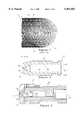
- FIG. 1is an example of a pattern made by a prior art circular jet when rotated and travered across a surface.
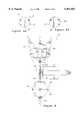
- FIG. 2.is a cross-sectional view of a nozzle illustrating a preferred embodiment of the present invention.
- FIG. 3is a cross-sectional view of the nozzle of FIG. 2 mounted in a receiving cone.
- FIGS. 4a-care diagrams illustrating the effect of changing an internal cone angle of the nozzle of FIG. 2 on the power distribution of a resulting fan jet.
- FIGS. 5a-care diagrams illustrating the effect of changing an external wedge angle of the nozzle of FIG. 2 on the shape of the resulting fan jet.
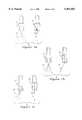
- FIGS. 6a-bare bottom plan views illustrating alternative embodiments of the nozzle of FIG. 2.
- FIGS. 7a-care diagrams illustrating front and side views of three alternative embodiments the nozzle of FIG. 2 and resulting fan jets.
- FIG. 8is a top plan view of a grinding fixture used to manufacture the nozzle of FIG. 2.
- ultrahigh-pressure fluid jetSuch jets may be generated by high-pressure, positive displacement pumps (not shown) and may reach pressures up to and beyond 55,000 psi.
- the pressurized fluid generated by the pumpis typically collected in a manifold from which the fluid is directed through the nozzle of a tool (not shown), thereby creating an ultra-high pressure jet that may be used to perform a particular task.
- a column of pressurized fluid having a circular cross sectionis typically used.
- circular jetsare beneficial in certain applications, for example cutting complex shapes
- a moving circular jetrepresents a moving point and therefore has severe limitations in other contexts such as cleaning.
- the current practice in cleaning a surface with a circular jetis to rotate and translate circular jets along a surface, resulting in the pattern 11 shown in FIG. 1.
- FIG. 1there are various shaped areas such as diamonds 13, crescents 15, and triangles 17, among others, that are never hit by the rotating and translating jets (not shown).
- FIG. 1 at 19there are several areas on the surface that are hit by the jets multiple times. As a result, the surface is not cleaned completely or evenly, resulting in a damaged surface.
- FIGS. 2 and 3illustrate a preferred embodiment of the present invention.
- a nozzle 12has a first end 14, a second end 16, an outer surface 18 and an inner surface 20.
- the inner surface 20is defined by a conical bore 22, that extends from the first end 14 to the second end 16, thereby creating an entrance orifice 24 and an exit orifice 26 in the first end 14 and second end 16, respectively.
- a wedge-shaped notch 28extends from the second end 16 in towards the first end 14 to a depth 44 such that the notch 28 and conical bore 22 intersect.
- the shape of the exit orifice 26is therefore defined by this intersection of the conical bore 22 and the wedge-shaped notch 28.
- the nozzle 12 in a preferred embodimentis mounted within a receiving cone 30, including a nozzle nut 31.
- the receiving cone 30acts against the nozzle 12 thereby placing the inner surface 20 of the nozzle 12 near and at the exit orifice 26 in a compressive state of stress.
- the nozzle 12is more resistant to fatigue and wear.
- the outer surface 18 of the nozzle 12is conical such that the second end 16 has a substantially circular planar surface 45, as illustrated in FIG. 6a.
- the wedge-shaped notch 28is aligned along a diameter of the circular surface 45, such that it passes through a center 47 of the second end 16.
- the fan jet of pressurized fluidwill exit the nozzle 12 in a direction substantially aligned with a longitudinal axis 50 of the nozzle 12.
- This fan jetmay be referred to as a "straight" fan 49, as illustrated in FIG. 7a.
- a straight fan 49may be useful in various contexts, for example, in cleaning or coating removal, as will be discussed in greater detail below.
- the wedge-shaped notch 28is offset such that it is not aligned along a diameter of the circular surface 45 of the second end 16.
- the fan jetwill exit the nozzle 12 at an angle relative to the longitudinal axis 50 of the nozzle 12.
- Such a fan jetmay be referred to as a "side-firing" fan 51, as illustrated in FIG. 7b.
- a side-firing fan jet 51may also be produced by grinding the wedge-shaped notch 28 at an angle relative to the longitudinal axis 50 of nozzle 12, such that the axis 50 of nozzle 12 is not in the plane of the notch 28.
- Side-firing fan jets 51may be useful in various contexts, for example, when it is necessary to clean or remove grout from sides of a narrow, deep area, such as a gap between two concrete blocks.
- the wedge-shaped notch 28may be at an angle relative to the longitudinal axis 50 of the nozzle 12 such that the axis 50 of the nozzle 12 is in the plane of the notch 28. This produces an "angled" fan jet 53, which is believed to be useful in various contexts.
- the pressurized fluid exiting the nozzle 12is in the form of a fan jet having a substantially linear footprint, the width of which varies with changes in the geometry of the nozzle.
- the footprintmay be viewed as a thin rectangle, or as an oval having a very high aspect ratio, such as 100 to 1, having a major axis and a minor axis.
- the geometry of the fan jetmay be controlled by adjusting the geometry of the nozzle, different geometries being more desirable depending on the task at hand. For example, in cleaning it is often desirable to selectively remove a layer of matter from an underlying surface, without damaging the underlying surface. It is also desirable and often necessary to have a 100% clean surface.
- the fan jet produced by the preferred embodiment of the nozzle 12 illustrated hereinBy sweeping the fan jet produced by the preferred embodiment of the nozzle 12 illustrated herein across a surface to be cleaned in the direction of the minor axis of the fan jet's footprint, it is possible to remove a layer of material evenly and completely, thereby avoiding the problems associated with the rotation and translation of a circular jet. It will be appreciated by one of ordinary skill in the art, that a number of nozzles 12 may be aligned and translated across a surface in unison to clean a larger area more quickly and efficiently. Alternatively, the fan jet may be swept across a surface to be cut in the direction of the major axis of the footprint, thereby providing a shearing, cutting force. Such a fan jet may be particularly well suited to cutting fibrous materials, although it would also provide an accurate, straight cut in a hard material.
- the geometry of the nozzle 12may be altered to control the resulting geometry and power distribution of the fan jet.
- an internal angle 34a of the conical bore 22is 90° to achieve a uniform power distribution 36a of the fan jet, such that the power at the center 40a at the ends 42a of the fan jet is the same.
- FIG. 4aan internal angle 34a of the conical bore 22 is 90° to achieve a uniform power distribution 36a of the fan jet, such that the power at the center 40a at the ends 42a of the fan jet is the same.
- the internal angle 34b of the conical bore 22is less than 90°, for example, 60°, thereby resulting in a power distribution 36b that is concentrated at a center 40b of the fan jet and tapers at the ends 42b of the fan jet.
- an internal angle 34c of the conical bore 22is greater than 90°, for example, 105°, resulting in a power distribution 36c that is concentrated on the ends 42c of the fan jet and minimal at the center 40c of the fan jet.
- changes to an external angle 33 of the wedge-shaped notch 28may be made to control the shape and thickness of the fan jet.
- a small wedge angle 33aproduces a wide-angled fan 35
- a large wedge angle 33cas shown in FIG. 5c
- the thickness of the fan jetalso increases with an increase in the wedge angle.
- a narrow-angled fansuch as that produced by the wide -angled wedge angle in FIG. 5c will be more focused in delivering power to a target, which may be necessary if the distance between the nozzle 12 and the surface being cleaned is great.
- the nozzle 12is manufactured by machining a blank 64 from any high-strength, metallic alloy, for example, annealed steel.
- the nozzle 12is made from Carpenter Custom 455 stainless steel.
- the conical bore 22is machined out of the blank, after which the inner surface 20 is finished by pressing a cone-shaped die (not shown) into the conical bore 22, thereby eliminating machining marks and improving the quality of the inner surface 20.
- the nozzle 12is then heat treated at a given temperature for a given amount of time, to increase the strength of the material. The correct temperature and time are dependent on the material used, and will be known by one of ordinary skill in the art.
- the nozzleis treated at 900° F. for four hours, and then air cooled.
- the outer surface 18 of the nozzle 12may be finished before or after the nozzle is heat treated.
- the outer surface 18is conical, such that the second end 16 has a substantially circular, planar surface 45.
- the grinding fixture 59includes two diamond dressers 60 which may be positioned to create a desired angle such that when the dressers 60 act against a grinding wheel 62, they will produce the same angle on the edge of the grinding wheel 62.
- Several of the blanks 64are mounted on a turret 66, which may move both laterally and longitudinally to align the blank 64 with the grinding wheel 62.
- a first blank 64is used to calibrate the system.
- An operator of the grinding fixture 59grinds a wedge-shaped notch 28 into the blank 64, and then rotates the turret 66 90° to inspect the alignment of the wedge-shaped notch 28 with the conical bore 22. This inspection is done through a microscope (not shown). If the wedge-shaped notch 28 is not properly aligned, adjustments are made by moving the turret 66. Once the desired alignment is achieved, multiple nozzles 12 may then be completed very quickly by mounting multiple blanks 64 on the turret 66 and grinding the wedge-shaped notch 28 via the grinding wheel 62.
- different depths of the wedge-shaped notch 28will be desired, depending on the intended task and the size of the nozzle, as measured by a diameter of the nozzle 12.
- the desired depthis calibrated and checked by measuring the length of a minor axis of the exit orifice 26 which will have an oval shape due to the intersection of the wedge-shaped notch 28 and the conical bore 22.
Landscapes
- Engineering & Computer Science (AREA)
- Mechanical Engineering (AREA)
- Life Sciences & Earth Sciences (AREA)
- Forests & Forestry (AREA)
- Nozzles (AREA)
Abstract
Description
Claims (6)
Priority Applications (2)
| Application Number | Priority Date | Filing Date | Title |
|---|---|---|---|
| US08/663,379US5961053A (en) | 1994-02-18 | 1996-06-13 | Ultrahigh-pressure fan jet nozzle |
| US09/041,048US6019298A (en) | 1992-12-08 | 1998-03-06 | Ultrahigh-pressure fan jet nozzle |
Applications Claiming Priority (3)
| Application Number | Priority Date | Filing Date | Title |
|---|---|---|---|
| US08/198,645US5417607A (en) | 1992-12-08 | 1994-02-18 | Ultrahigh-pressure fan jet nozzle |
| US38836995A | 1995-02-14 | 1995-02-14 | |
| US08/663,379US5961053A (en) | 1994-02-18 | 1996-06-13 | Ultrahigh-pressure fan jet nozzle |
Related Parent Applications (1)
| Application Number | Title | Priority Date | Filing Date |
|---|---|---|---|
| US38836995AContinuation | 1992-12-08 | 1995-02-14 |
Related Child Applications (1)
| Application Number | Title | Priority Date | Filing Date |
|---|---|---|---|
| US09/041,048ContinuationUS6019298A (en) | 1992-12-08 | 1998-03-06 | Ultrahigh-pressure fan jet nozzle |
Publications (1)
| Publication Number | Publication Date |
|---|---|
| US5961053Atrue US5961053A (en) | 1999-10-05 |
Family
ID=26894011
Family Applications (2)
| Application Number | Title | Priority Date | Filing Date |
|---|---|---|---|
| US08/663,379Expired - Fee RelatedUS5961053A (en) | 1992-12-08 | 1996-06-13 | Ultrahigh-pressure fan jet nozzle |
| US09/041,048Expired - Fee RelatedUS6019298A (en) | 1992-12-08 | 1998-03-06 | Ultrahigh-pressure fan jet nozzle |
Family Applications After (1)
| Application Number | Title | Priority Date | Filing Date |
|---|---|---|---|
| US09/041,048Expired - Fee RelatedUS6019298A (en) | 1992-12-08 | 1998-03-06 | Ultrahigh-pressure fan jet nozzle |
Country Status (1)
| Country | Link |
|---|---|
| US (2) | US5961053A (en) |
Cited By (8)
| Publication number | Priority date | Publication date | Assignee | Title |
|---|---|---|---|---|
| US6402062B1 (en)* | 1999-04-22 | 2002-06-11 | Lechler Gmbh + Co. Kg | High-pressure spray nozzle |
| US6418999B1 (en) | 1997-12-26 | 2002-07-16 | Cannon Kabushiki Kaisha | Sample separating apparatus and method, and substrate manufacturing method |
| US7829036B2 (en) | 2005-06-14 | 2010-11-09 | Unifrax I Llc | Fluid jet cutting process |
| US20100286636A1 (en)* | 2009-05-11 | 2010-11-11 | Medaxis Ag | Disposable nozzle |
| EP2251142A1 (en)* | 2009-05-11 | 2010-11-17 | Medaxis Ag | Disposable nozzle |
| USD640295S1 (en)* | 2010-04-01 | 2011-06-21 | IBEG, Inc. | Nozzle for a sand jet |
| US20140352727A1 (en)* | 2013-05-31 | 2014-12-04 | General Electric Company | Dry steam cleaning a surface |
| CN105983489A (en)* | 2015-03-16 | 2016-10-05 | 莱希勒有限公司 | Flat jet nozzle, and use of a flat jet nozzle |
Families Citing this family (5)
| Publication number | Priority date | Publication date | Assignee | Title |
|---|---|---|---|---|
| SE521301C2 (en)* | 1998-12-08 | 2003-10-21 | Eftec Europe Holding Ag | sealing nozzle |
| AU2002235542A1 (en)* | 2000-08-22 | 2002-03-04 | Microcoating Technologies, Inc. | Narrow diameter needle having reduced inner diameter tip |
| ITMI20030676A1 (en)* | 2003-04-07 | 2004-10-08 | Auges S R L | DEVICE AND METHOD TO DELIVER A LUBRICANT AND / OR REFRIGERANT FLUID IN MECHANICAL PROCESSING |
| US8187056B2 (en)* | 2006-12-14 | 2012-05-29 | Flow International Corporation | Process and apparatus for surface-finishing |
| WO2009154567A1 (en)* | 2008-06-20 | 2009-12-23 | Aem Singapore Pte Ltd | A wear-resistant high-pressure water jet nozzle |
Citations (27)
| Publication number | Priority date | Publication date | Assignee | Title |
|---|---|---|---|---|
| FR989083A (en)* | 1949-04-21 | 1951-09-04 | Improvements to liquid projection tablets | |
| US2618989A (en)* | 1948-06-01 | 1952-11-25 | John A Cupler | Method of manufacturing orificed members |
| DE1063535B (en)* | 1952-12-19 | 1959-08-13 | Hugo Tafelmaier | Atomizer nozzle and milling disc for making the atomizer slot in the nozzle body |
| US3168848A (en)* | 1961-08-10 | 1965-02-09 | Hauni Werke Koerber & Co Kg | Cutting mechanism for rod-making machines |
| US3540166A (en)* | 1968-10-02 | 1970-11-17 | James B Crumley | Can opener cleaner-sharpener accessory |
| US3556411A (en)* | 1968-05-22 | 1971-01-19 | Nordson Corp | Spray nozzle |
| US3659787A (en)* | 1969-04-16 | 1972-05-02 | Ransburg Electro Coating Corp | Nozzle |
| US3709436A (en)* | 1971-01-06 | 1973-01-09 | Heist Corp C H | High pressure jet cleaning device |
| US3726481A (en)* | 1971-01-06 | 1973-04-10 | Heist Corp C H | High pressure jet cleaning device |
| US3756106A (en)* | 1971-03-01 | 1973-09-04 | Bendix Corp | Nozzle for producing fluid cutting jet |
| US3843055A (en)* | 1973-07-18 | 1974-10-22 | Nordson Corp | Spray nozzle |
| US3865314A (en)* | 1974-02-19 | 1975-02-11 | Said Levey By Said Moser | Adjustable pattern spray gun |
| US3897002A (en)* | 1974-08-14 | 1975-07-29 | Baxter Laboratories Inc | Liquid wash injector |
| US3960407A (en)* | 1972-10-03 | 1976-06-01 | Atlas Copco Aktiebolag | Cutters and methods of cutting |
| US3997111A (en)* | 1975-07-21 | 1976-12-14 | Flow Research, Inc. | Liquid jet cutting apparatus and method |
| US4097000A (en)* | 1975-07-07 | 1978-06-27 | Derr Bernard A | Spray nozzle |
| US4111490A (en)* | 1975-09-05 | 1978-09-05 | Liesveld Daniel J | Method and apparatus for channel cutting of hard materials using high velocity fluid jets |
| DE2736314A1 (en)* | 1977-08-12 | 1979-02-22 | Kaercher Gmbh & Co Alfred | DUESE FOR SPRAYING A PRESSURIZED MEDIUM |
| US4150794A (en)* | 1977-07-26 | 1979-04-24 | Camsco, Inc. | Liquid jet cutting nozzle and housing |
| US4216906A (en)* | 1976-06-21 | 1980-08-12 | Flow Research, Inc. | Method of making high velocity liquid jet |
| US4508577A (en)* | 1983-04-29 | 1985-04-02 | Tracor Hydronautics, Inc. | Fluid jet apparatus and method for cleaning tubular components |
| US4537639A (en)* | 1983-09-12 | 1985-08-27 | Nlb Corp. | Method for cleaning weld smut from a surface |
| US4845903A (en)* | 1987-01-16 | 1989-07-11 | Weatherford Italiana S.P.A. | Sandblasting device |
| US5052624A (en)* | 1988-03-11 | 1991-10-01 | Possis Corporation | Ultra high pressure water cleaning tool |
| US5116425A (en)* | 1990-06-07 | 1992-05-26 | Softblast, Inc. | Cleaning method |
| US5167721A (en)* | 1989-11-27 | 1992-12-01 | United Technologies Corporation | Liquid jet removal of plasma sprayed and sintered |
| US5288027A (en)* | 1992-07-17 | 1994-02-22 | Nordson Corporation | Dispensing method and apparatus including a ribbon nozzle for coating printed circuit boards |
Family Cites Families (3)
| Publication number | Priority date | Publication date | Assignee | Title |
|---|---|---|---|---|
| US1051069A (en)* | 1911-10-21 | 1913-01-21 | Carl Boehme | Oil-burner tip. |
| US1753443A (en)* | 1927-05-31 | 1930-04-08 | John D Murray | Tip for spraying nozzles |
| DE4341870B4 (en)* | 1992-12-08 | 2008-03-13 | Flow International Corp., Kent | Ultra high-pressure flat-jet nozzle |
- 1996
- 1996-06-13USUS08/663,379patent/US5961053A/ennot_activeExpired - Fee Related
- 1998
- 1998-03-06USUS09/041,048patent/US6019298A/ennot_activeExpired - Fee Related
Patent Citations (27)
| Publication number | Priority date | Publication date | Assignee | Title |
|---|---|---|---|---|
| US2618989A (en)* | 1948-06-01 | 1952-11-25 | John A Cupler | Method of manufacturing orificed members |
| FR989083A (en)* | 1949-04-21 | 1951-09-04 | Improvements to liquid projection tablets | |
| DE1063535B (en)* | 1952-12-19 | 1959-08-13 | Hugo Tafelmaier | Atomizer nozzle and milling disc for making the atomizer slot in the nozzle body |
| US3168848A (en)* | 1961-08-10 | 1965-02-09 | Hauni Werke Koerber & Co Kg | Cutting mechanism for rod-making machines |
| US3556411A (en)* | 1968-05-22 | 1971-01-19 | Nordson Corp | Spray nozzle |
| US3540166A (en)* | 1968-10-02 | 1970-11-17 | James B Crumley | Can opener cleaner-sharpener accessory |
| US3659787A (en)* | 1969-04-16 | 1972-05-02 | Ransburg Electro Coating Corp | Nozzle |
| US3709436A (en)* | 1971-01-06 | 1973-01-09 | Heist Corp C H | High pressure jet cleaning device |
| US3726481A (en)* | 1971-01-06 | 1973-04-10 | Heist Corp C H | High pressure jet cleaning device |
| US3756106A (en)* | 1971-03-01 | 1973-09-04 | Bendix Corp | Nozzle for producing fluid cutting jet |
| US3960407A (en)* | 1972-10-03 | 1976-06-01 | Atlas Copco Aktiebolag | Cutters and methods of cutting |
| US3843055A (en)* | 1973-07-18 | 1974-10-22 | Nordson Corp | Spray nozzle |
| US3865314A (en)* | 1974-02-19 | 1975-02-11 | Said Levey By Said Moser | Adjustable pattern spray gun |
| US3897002A (en)* | 1974-08-14 | 1975-07-29 | Baxter Laboratories Inc | Liquid wash injector |
| US4097000A (en)* | 1975-07-07 | 1978-06-27 | Derr Bernard A | Spray nozzle |
| US3997111A (en)* | 1975-07-21 | 1976-12-14 | Flow Research, Inc. | Liquid jet cutting apparatus and method |
| US4111490A (en)* | 1975-09-05 | 1978-09-05 | Liesveld Daniel J | Method and apparatus for channel cutting of hard materials using high velocity fluid jets |
| US4216906A (en)* | 1976-06-21 | 1980-08-12 | Flow Research, Inc. | Method of making high velocity liquid jet |
| US4150794A (en)* | 1977-07-26 | 1979-04-24 | Camsco, Inc. | Liquid jet cutting nozzle and housing |
| DE2736314A1 (en)* | 1977-08-12 | 1979-02-22 | Kaercher Gmbh & Co Alfred | DUESE FOR SPRAYING A PRESSURIZED MEDIUM |
| US4508577A (en)* | 1983-04-29 | 1985-04-02 | Tracor Hydronautics, Inc. | Fluid jet apparatus and method for cleaning tubular components |
| US4537639A (en)* | 1983-09-12 | 1985-08-27 | Nlb Corp. | Method for cleaning weld smut from a surface |
| US4845903A (en)* | 1987-01-16 | 1989-07-11 | Weatherford Italiana S.P.A. | Sandblasting device |
| US5052624A (en)* | 1988-03-11 | 1991-10-01 | Possis Corporation | Ultra high pressure water cleaning tool |
| US5167721A (en)* | 1989-11-27 | 1992-12-01 | United Technologies Corporation | Liquid jet removal of plasma sprayed and sintered |
| US5116425A (en)* | 1990-06-07 | 1992-05-26 | Softblast, Inc. | Cleaning method |
| US5288027A (en)* | 1992-07-17 | 1994-02-22 | Nordson Corporation | Dispensing method and apparatus including a ribbon nozzle for coating printed circuit boards |
Non-Patent Citations (8)
| Title |
|---|
| Applicant received promotional material regarding jet nozzles manufactured by High Energy Jets Ltd. on Feb. 27, 1986.* |
| Brochure entitled Long Life Nozzles for High Pressure Jetting Applications, High Energy Jets Ltd., West Midlands, United Kingdom (3 pages).* |
| Brochure for "A Technical Breakthrough in Fan Jets: A New Concept in Nozzle Design," by High Energy Jets, Ltd. |
| Brochure for A Technical Breakthrough in Fan Jets: A New Concept in Nozzle Design, by High Energy Jets, Ltd.* |
| Engineering description of GRACO P/N 163 XXX Fan Jet Nozzle prepared by R. Cox for Advanced Mining and Construction, Sep. 6, 1984 (1 page).* |
| Engineering description of GRACO P/N 163-XXX Fan Jet Nozzle prepared by R. Cox for Advanced Mining and Construction, Sep. 6, 1984 (1 page). |
| Prototype of Jet Nozzle sold on Oct. 1, 1991 (Attachment A).* |
| WOMA Jet Nozzle (Attachment B).* |
Cited By (13)
| Publication number | Priority date | Publication date | Assignee | Title |
|---|---|---|---|---|
| US6418999B1 (en) | 1997-12-26 | 2002-07-16 | Cannon Kabushiki Kaisha | Sample separating apparatus and method, and substrate manufacturing method |
| US6521078B2 (en) | 1997-12-26 | 2003-02-18 | Canon Kabushiki Kaisha | Sample separating apparatus and method, and substrate manufacturing method |
| US20030102082A1 (en)* | 1997-12-26 | 2003-06-05 | Kazutaka Yanagita | Sample separating apparatus and method, and substrate manufacturing method |
| US6860963B2 (en) | 1997-12-26 | 2005-03-01 | Canon Kabushiki Kaisha | Sample separating apparatus and method, and substrate manufacturing method |
| US6402062B1 (en)* | 1999-04-22 | 2002-06-11 | Lechler Gmbh + Co. Kg | High-pressure spray nozzle |
| US7829036B2 (en) | 2005-06-14 | 2010-11-09 | Unifrax I Llc | Fluid jet cutting process |
| US20100286636A1 (en)* | 2009-05-11 | 2010-11-11 | Medaxis Ag | Disposable nozzle |
| EP2251142A1 (en)* | 2009-05-11 | 2010-11-17 | Medaxis Ag | Disposable nozzle |
| USD640295S1 (en)* | 2010-04-01 | 2011-06-21 | IBEG, Inc. | Nozzle for a sand jet |
| USD640296S1 (en)* | 2010-04-01 | 2011-06-21 | IBEG, Inc. | Nozzle for a sand jet |
| US20140352727A1 (en)* | 2013-05-31 | 2014-12-04 | General Electric Company | Dry steam cleaning a surface |
| US10577968B2 (en)* | 2013-05-31 | 2020-03-03 | General Electric Company | Dry steam cleaning a surface |
| CN105983489A (en)* | 2015-03-16 | 2016-10-05 | 莱希勒有限公司 | Flat jet nozzle, and use of a flat jet nozzle |
Also Published As
| Publication number | Publication date |
|---|---|
| US6019298A (en) | 2000-02-01 |
Similar Documents
| Publication | Publication Date | Title |
|---|---|---|
| US5417607A (en) | Ultrahigh-pressure fan jet nozzle | |
| US5942045A (en) | Hard coating removal with ultrahigh-pressure fan jets | |
| US5961053A (en) | Ultrahigh-pressure fan jet nozzle | |
| DE10297131B4 (en) | Nozzle for coherent radiation in grinding applications | |
| EP2741862B1 (en) | Device for generating a pulsating fluid jet subjected to pressure | |
| DE19713519C2 (en) | Process for the pretreatment and coating of aluminum bore surfaces | |
| EP2546026B1 (en) | Apparatus for formation of laterally directed fluid jets | |
| EP0565742B1 (en) | Procedure of fine machining workpiece surfaces | |
| Hocheng et al. | Material removal analysis in abrasive waterjet cutting of ceramic plates | |
| US5380068A (en) | Deep kerfing in rocks with ultrahigh-pressure fan jets | |
| WO2004028739A1 (en) | Method and device for creating internal compression stresses within the surface of workpieces | |
| EP1986817B1 (en) | Peening chamber for surface peening, in particular for ultrasonic shot peening of gas turbine components | |
| WO2014202491A1 (en) | Method and system for preparing and coating a workpiece surface | |
| CN107835731A (en) | With the method for pure water jets cutting fibre enhancing polymer composites workpiece | |
| US11559872B2 (en) | Device and method for the surface treatment of a material | |
| EP2308646B1 (en) | Method for working on workpieces by means of a water jet that contains abrasive and emerges under high pressure from a nozzle, water jet installation for executing the method, and application of the method | |
| Hashish | Controlled-depth milling of isogrid structures with AWJs | |
| EP1618993B1 (en) | Process for grinding and/or polishing surfaces | |
| CN101674922A (en) | Method for hardening a machined article | |
| Peng et al. | Research on single-point diamond fly-grooving of brittle materials | |
| RU2348505C2 (en) | Method for rounding of part edges | |
| CN110331266B (en) | Ultrasonic liquid knife impacting metal material surface nanocrystallization method and special device thereof | |
| DE202020004003U1 (en) | Machine tool for laser conditioning of grinding tools regardless of their specification | |
| EP1954421B1 (en) | Method for producing metallic components, particularly for turbo machines, having small edge radii, and component produced therewith | |
| EP1406749A1 (en) | Device for the removal of material arranged within a workpiece |
Legal Events
| Date | Code | Title | Description |
|---|---|---|---|
| AS | Assignment | Owner name:JOHN HANCOCK LIFE INSURANCE COMPANY, AS COLLATERAL Free format text:SECURITY INTEREST;ASSIGNOR:FLOW INTERNATIONAL CORPORATION;REEL/FRAME:013447/0301 Effective date:20021001 | |
| FPAY | Fee payment | Year of fee payment:4 | |
| AS | Assignment | Owner name:BANK OF AMERICA, N.A.,WASHINGTON Free format text:SECURITY AGREEMENT;ASSIGNOR:FLOW INTERNATIONAL CORPORATION;REEL/FRAME:016283/0522 Effective date:20050708 Owner name:BANK OF AMERICA, N.A., WASHINGTON Free format text:SECURITY AGREEMENT;ASSIGNOR:FLOW INTERNATIONAL CORPORATION;REEL/FRAME:016283/0522 Effective date:20050708 | |
| AS | Assignment | Owner name:FLOW INTERNATIONAL CORPORATION, WASHINGTON Free format text:RELEASE BY SECURED PARTY;ASSIGNOR:JOHN HANCOCK LIFE INSURANCE COMPANY;REEL/FRAME:016761/0670 Effective date:20051031 | |
| FPAY | Fee payment | Year of fee payment:8 | |
| AS | Assignment | Owner name:BANK OF AMERICA, N.A., WASHINGTON Free format text:SECURITY AGREEMENT;ASSIGNOR:FLOW INTERNATIONAL CORPORATION;REEL/FRAME:021138/0738 Effective date:20080609 Owner name:BANK OF AMERICA, N.A.,WASHINGTON Free format text:SECURITY AGREEMENT;ASSIGNOR:FLOW INTERNATIONAL CORPORATION;REEL/FRAME:021138/0738 Effective date:20080609 | |
| AS | Assignment | Owner name:BANK OF AMERICA, N.A., WASHINGTON Free format text:NOTICE OF GRANT OF SECURITY INTEREST;ASSIGNOR:FLOW INTERNATIONAL CORPORATION;REEL/FRAME:022813/0733 Effective date:20090610 Owner name:BANK OF AMERICA, N.A.,WASHINGTON Free format text:NOTICE OF GRANT OF SECURITY INTEREST;ASSIGNOR:FLOW INTERNATIONAL CORPORATION;REEL/FRAME:022813/0733 Effective date:20090610 | |
| AS | Assignment | Owner name:FLOW INTERNATIONAL CORPORATION, WASHINGTON Free format text:ASSIGNMENT OF ASSIGNORS INTEREST;ASSIGNORS:RAGHAVAN, CHIDAMBARAM;TING, EDMUND Y.;TREMOULET, OLIVIER L., JR.;AND OTHERS;REEL/FRAME:023094/0727 Effective date:19921208 | |
| REMI | Maintenance fee reminder mailed | ||
| LAPS | Lapse for failure to pay maintenance fees | ||
| STCH | Information on status: patent discontinuation | Free format text:PATENT EXPIRED DUE TO NONPAYMENT OF MAINTENANCE FEES UNDER 37 CFR 1.362 | |
| FP | Lapsed due to failure to pay maintenance fee | Effective date:20111005 |