US5960992A - Aseptic brick package spout - Google Patents
Aseptic brick package spoutDownload PDFInfo
- Publication number
- US5960992A US5960992AUS08/868,818US86881897AUS5960992AUS 5960992 AUS5960992 AUS 5960992AUS 86881897 AUS86881897 AUS 86881897AUS 5960992 AUS5960992 AUS 5960992A
- Authority
- US
- United States
- Prior art keywords
- cutter
- carton
- bars
- pour spout
- fitment
- Prior art date
- Legal status (The legal status is an assumption and is not a legal conclusion. Google has not performed a legal analysis and makes no representation as to the accuracy of the status listed.)
- Expired - Lifetime
Links
- 239000011449brickSubstances0.000titleabstractdescription13
- 239000012528membraneSubstances0.000claimsabstractdescription23
- 230000036346tooth eruptionEffects0.000claimsabstractdescription16
- 238000010276constructionMethods0.000claimsdescription13
- 239000007788liquidSubstances0.000abstractdescription22
- 238000001125extrusionMethods0.000abstractdescription11
- 238000009455aseptic packagingMethods0.000abstractdescription2
- 238000007765extrusion coatingMethods0.000abstract1
- 239000000853adhesiveSubstances0.000description16
- 230000001070adhesive effectEffects0.000description16
- 239000004033plasticSubstances0.000description11
- 229920003023plasticPolymers0.000description11
- 230000004888barrier functionEffects0.000description10
- 239000011324beadSubstances0.000description9
- 238000005520cutting processMethods0.000description8
- 239000011087paperboardSubstances0.000description8
- 239000000463materialSubstances0.000description7
- 239000004831Hot glueSubstances0.000description5
- 230000009471actionEffects0.000description5
- 235000015203fruit juiceNutrition0.000description3
- 238000000576coating methodMethods0.000description2
- 238000009826distributionMethods0.000description2
- 238000001914filtrationMethods0.000description2
- 239000011521glassSubstances0.000description2
- 239000003292glueSubstances0.000description2
- 235000013336milkNutrition0.000description2
- 239000008267milkSubstances0.000description2
- 210000004080milkAnatomy0.000description2
- 230000004048modificationEffects0.000description2
- 238000012986modificationMethods0.000description2
- 238000004806packaging method and processMethods0.000description2
- 238000007789sealingMethods0.000description2
- 239000011800void materialSubstances0.000description2
- 239000004698PolyethyleneSubstances0.000description1
- 208000027418Wounds and injuryDiseases0.000description1
- 238000005452bendingMethods0.000description1
- 230000015572biosynthetic processEffects0.000description1
- 239000011248coating agentSubstances0.000description1
- 230000006378damageEffects0.000description1
- 230000035622drinkingEffects0.000description1
- 239000011888foilSubstances0.000description1
- 230000004927fusionEffects0.000description1
- 239000012943hotmeltSubstances0.000description1
- 208000014674injuryDiseases0.000description1
- 230000003993interactionEffects0.000description1
- 238000005304joiningMethods0.000description1
- 238000004519manufacturing processMethods0.000description1
- 238000000034methodMethods0.000description1
- 239000002991molded plasticSubstances0.000description1
- 238000000465mouldingMethods0.000description1
- 230000002093peripheral effectEffects0.000description1
- -1polyethylenePolymers0.000description1
- 229920000573polyethylenePolymers0.000description1
- 230000008569processEffects0.000description1
- 230000002787reinforcementEffects0.000description1
- 239000012858resilient materialSubstances0.000description1
Images


Classifications
- B—PERFORMING OPERATIONS; TRANSPORTING
- B67—OPENING, CLOSING OR CLEANING BOTTLES, JARS OR SIMILAR CONTAINERS; LIQUID HANDLING
- B67B—APPLYING CLOSURE MEMBERS TO BOTTLES JARS, OR SIMILAR CONTAINERS; OPENING CLOSED CONTAINERS
- B67B7/00—Hand- or power-operated devices for opening closed containers
- B67B7/24—Hole-piercing devices
- B67B7/26—Hole-piercing devices combined with spouts
- B—PERFORMING OPERATIONS; TRANSPORTING
- B65—CONVEYING; PACKING; STORING; HANDLING THIN OR FILAMENTARY MATERIAL
- B65D—CONTAINERS FOR STORAGE OR TRANSPORT OF ARTICLES OR MATERIALS, e.g. BAGS, BARRELS, BOTTLES, BOXES, CANS, CARTONS, CRATES, DRUMS, JARS, TANKS, HOPPERS, FORWARDING CONTAINERS; ACCESSORIES, CLOSURES, OR FITTINGS THEREFOR; PACKAGING ELEMENTS; PACKAGES
- B65D5/00—Rigid or semi-rigid containers of polygonal cross-section, e.g. boxes, cartons or trays, formed by folding or erecting one or more blanks made of paper
- B65D5/42—Details of containers or of foldable or erectable container blanks
- B65D5/72—Contents-dispensing means
- B65D5/74—Spouts
- B65D5/746—Spouts formed separately from the container
- B65D5/747—Spouts formed separately from the container with means for piercing or cutting the container wall or a membrane connected to said wall
- B65D5/748—Spouts formed separately from the container with means for piercing or cutting the container wall or a membrane connected to said wall a major part of the container wall or membrane being left inside the container after the opening
- B—PERFORMING OPERATIONS; TRANSPORTING
- B65—CONVEYING; PACKING; STORING; HANDLING THIN OR FILAMENTARY MATERIAL
- B65D—CONTAINERS FOR STORAGE OR TRANSPORT OF ARTICLES OR MATERIALS, e.g. BAGS, BARRELS, BOTTLES, BOXES, CANS, CARTONS, CRATES, DRUMS, JARS, TANKS, HOPPERS, FORWARDING CONTAINERS; ACCESSORIES, CLOSURES, OR FITTINGS THEREFOR; PACKAGING ELEMENTS; PACKAGES
- B65D2251/00—Details relating to container closures
- B65D2251/0003—Two or more closures
- B65D2251/0006—Upper closure
- B65D2251/0015—Upper closure of the 41-type
- B—PERFORMING OPERATIONS; TRANSPORTING
- B65—CONVEYING; PACKING; STORING; HANDLING THIN OR FILAMENTARY MATERIAL
- B65D—CONTAINERS FOR STORAGE OR TRANSPORT OF ARTICLES OR MATERIALS, e.g. BAGS, BARRELS, BOTTLES, BOXES, CANS, CARTONS, CRATES, DRUMS, JARS, TANKS, HOPPERS, FORWARDING CONTAINERS; ACCESSORIES, CLOSURES, OR FITTINGS THEREFOR; PACKAGING ELEMENTS; PACKAGES
- B65D2251/00—Details relating to container closures
- B65D2251/0003—Two or more closures
- B65D2251/0037—Intermediate closure(s)
- B65D2251/0056—Intermediate closure(s) of the 47-type
- B—PERFORMING OPERATIONS; TRANSPORTING
- B65—CONVEYING; PACKING; STORING; HANDLING THIN OR FILAMENTARY MATERIAL
- B65D—CONTAINERS FOR STORAGE OR TRANSPORT OF ARTICLES OR MATERIALS, e.g. BAGS, BARRELS, BOTTLES, BOXES, CANS, CARTONS, CRATES, DRUMS, JARS, TANKS, HOPPERS, FORWARDING CONTAINERS; ACCESSORIES, CLOSURES, OR FITTINGS THEREFOR; PACKAGING ELEMENTS; PACKAGES
- B65D2251/00—Details relating to container closures
- B65D2251/0003—Two or more closures
- B65D2251/0068—Lower closure
- B65D2251/0093—Membrane
- B65D2251/0096—Membrane integral with the container
Definitions
- This inventionrelates to containers and more particularly to brick-type containers fashioned from paperboard and particularly adapted for aseptic packaging of liquids and other foodstuffs.
- Brick-type containersare in the general form of a rectangular parallelepiped, and take their name from their resemblance in shape to a common masonry brick.
- one end of the packageis provided with a plastic fitment, the fitment including a screw cap and a pouring nozzle.
- the material from which the container is fashionedis typically paperboard coated on one or both of its surfaces with one or more layers of various known barrier materials such as polymeric barrier materials.
- optimum dimensions and proportions of a pour fitment and an aseptic brick packageare employed.
- the specific adhesives employed, the area of adhesive coverage needed to prevent leakage, the amount of adhesive, and the specific location of the fitment on the package, as well as the extrusion over void area over the pour spout dispensing openingare employed for optimum results.
- the pour spout fitmentsare located above the incoming filled aseptic brick packages, the packages being filled with milk or fruit juice.
- a hot melt adhesive bead or ringis applied around the perimeter of a dispensing opening which is spanned and closed by one or more barrier layers coating the paperboard.
- the fitmentprovided with a lower flange and of molded plastic, is placed on top of the hot melt adhesive and pressure is applied.
- the filled brick containersare conveyed, over a period of three to five seconds, with pressure maintained on the fitment flange area, to set the hot melt adhesive.
- the completed packagesare conveyed to a pallet area for loading and packaging.
- pairs of liquid filled containers with their sides bulging somewhat from the weight of liquid thereinare placed into pockets or nests in a carousel.
- the side walls of the pocketsare fitted with bladders on each inner side wall.
- the bladdersare inflated by cam action using pneumatic valves. This squeezes the sides of the brick package forcing the liquid level upward, causing the top surfaces of the brick packages to become firm. In this way, when a fitment flange is placed above the adhesive ring and pushed down, the container top will not bend downwardly due to the incompressibility of the liquid, and a firm adhesive bond will result.
- FIG. 1is a plan view of a unitary paperboard blank from which the carton of this invention is formed.
- FIG. 2is a perspective view of a formed, filled and sealed aseptic container according to the practice of this invention.
- FIG. 3is a view illustrating the container of FIG. 2 after it has been placed in a pocket of a pocketed conveyor.
- FIG. 4is a view similar to FIG. 3 and illustrates the aseptic container after it has been provided with a continuous bead of a hot melt adhesive around its upper dispensing opening.
- FIG. 5is a view similar to FIG. 4 and illustrates the placement of the fitment on the aseptic container while the container is still in a pocket of a pocketed conveyor.
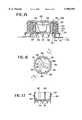
- FIG. 6is a view of a filled carton, the carton provided with a three component plastic pour and rupture fitment shown as exploded.
- FIGS. 7, 8, and 9are respective transverse cross sectional views of the three parts of the fitment of FIG. 6.
- FIGS. 10 and 11are transverse sections illustrating the seal piercing action of the fitment.
- FIG. 12is a view taken substantially along section 12--12 of FIG. 10.
- FIG. 13is a view similar to FIG. 12 and illustrates the addition of a cross element molded into the lower portion of cutting element 90 shown at FIG. 9.
- FIG. 14is a view similar to FIG. 9 and shows a cross element molded into the lower portion of cutting element 90 of the latter.
- FIG. 15is a transverse cross-sectional view of a complete fitment according to yet another modification of the invention.
- FIG. 16is a top plan view of the cutter element of FIG. 15.
- FIG. 17is a view taken along section 17--17 of FIG. 16.
- a unitary blank of paperboard or other stiff, foldable and resilient materialis designated as 10.
- the blankis rectangular with its central longitudinal axis horizontal and its central transverse axis vertical and has two horizontal score lines 12.
- Vertically extending fold lines 20, 24, 26 and 28extend from the top to the bottom edges of the blank, with the distance between the left and right blank edges and respective score lines 20 defining left and right borders or strips 30.
- Forty-five degree score lines 32extend from the four corners, respectively, to the intersection of score lines 24 and 12.
- Forty-five degree score linesare also located, as indicated, at the middle of the blank and extend from respective points on respective score lines 14 to the intersections, respectively, with score lines 26 and 12.
- Dispensing aperture 36is cut through the blank, with its center being below the top edge of the blank on imaginary axis 38 which intersects score line 28.
- Polymeric extrusion barrier layers 47cover both surfaces of the blank, as shown at FIG. 10 and 11, and are squeezed together to form a layer 48 which spans opening 36.
- the above described score linesdefine panels 40, 42, and 46, with panels 40 defining the front and rear walls of the carton and panels 42, when folded together with their edges, define side walls of the carton.
- the top of the cartonis defined by panels 44, while the bottom of the carton is defined by panels 46.
- the length of blank 10is about 18.58 inches (472 mm) and its width is about 6.70 inches (170.2 mm).
- the blank of FIG. 1is folded and glued and filled with a liquid in a manner known in this art to form a brick type package shown at FIG. 2.
- Triangular flaps 45extend from the top of the carton and down onto the sidewalls and overlap side seams defined by sealing together zones 16. Flaps similar to 45 are formed at the bottom of the carton, with flaps 45 defined from the upper and lower ends of panels 44, with the (not illustrated) corresponding triangular flaps of the bottom defined by the upper and lower edges of panels 46.
- the general shape and the manner of formation of the carton shown at FIG. 2is known in this art.
- the height of the carton or containeris about 6.57 inches (167 mm) and its thickness is about 2.44 inches (62 mm) and its width is about 3.70 inches (94.2 mm).
- FIG. 3the cartons of FIG. 2 have been placed in a pocket or nest on a conveyor, the pocket defined by upstanding sidewalls 50.
- an endless conveyor of any conventional constructioncarries a plurality of such pockets and it only be necessary to illustrate one pocket for an understanding of this invention.
- FIG. 4is similar to FIG. 3 except for a ring or band of adhesive 60 having been placed around dispensing opening 36.
- the dimensions of this ring of adhesiveare critical, as is the location of dispensing opening 36 relative to the top of the container.
- the bead 60is 0.125 inches (3.2 mm) wide.
- FIG. 5a flanged plastic pour spout fitment has been placed on top of the container.
- the flange of the plastic pour spout fitment(shortly to be described) has been placed onto adhesive ring 60 and squeezed downwardly.
- Such downward motionwould ordinarily cause a flexing or bending down of the top of the container.
- Such flexingwould result in an improper adhesive connection between the plastic fitment and the container.
- the outward bulges of the containerno longer exist and the top of the liquid is forced against the bottom of the top closure, as explained above.
- the top of the liquidthus provides a firm backing when the plastic fitment is pushed down upon and secured to the container.
- the liquidhas a head space above it, instead of the liquid contacting the top, then the increased air pressure will provide a firm backing.
- the flange of the fitmentis 0.125 inches (3.2 mm) from the nearest edge of the container, while the diameter of the flange is 1.625 inches (41.3 mm).
- the filled container with adhesive ring or bead 60 around its dispensing opening, the latter closed by the above described barrier layer material,is shown in relation to the plastic fitment, the latter shown exploded.
- Thisprovides exactly the right amount of adhesive to fill the dam between the rings 102 and 104 on the bottom of the spout flange when pressure is applied in the fitment application process.
- the fitmentis shown in detail at FIGS. 7, 8, and 9 and includes an outer screw cap 70, an intermediate flanged spout member 80, and a piercing element 90, the latter adapted to the frangible barrier layer material 48 spanning the dispensing opening at the time of initial dispensing of the contents.
- FIG. 7illustrates outermost plastic cap 70 which includes a plurality of internal threads 72, four downwardly extending arms 74, and a tamper evident band.
- FIG. 8shows the intermediate fitment spout member 80 having a plurality of inner threads 82 and outer threads 84, the latter terminating in a base flange 86.
- the outside diameter of flange 86is 1.625 inches (41.3 mm) and was determined to be optimum in terms of: (a) providing enough surface area for bonding to the package; and, (b) being small enough to allow placement of the pour hole opening as close as possible to the pouring edge of the carton. The closer the pour hole is to the carton edge, the easier it is to pour without spill.
- the flange of the fitmentis 0.125 inches (3.2 mm) from the score line that forms the pouring edge of the carton.
- the thickness of flange 86is 0.02 inches (0.5 mm), not including the height of glue dams 102 and 104.
- Abutments 88, shown also at FIG. 6,are positioned at 90 degree intervals around the upper portion of flange 86.
- FIG. 9shows cutting element 90 having a plurality of external threads 92, four vertically extending ribs 94 and lower circumferential cutting teeth 96, the latter terminating in tips 97.
- Teeth 96are interrupted by annularly spaced inverted V shaped drain grooves 98. Grooves 98 provide improved liquid evacuation from the package.
- the height of cutting teethis 0.125 inches (3.2 mm). This tooth height has been determined to be critical in yielding a clean cut on extrusion layer 48, as opposed to a ragged opening. The spout of the fitment was designed especially for adhesion to the aseptic package.
- the flange 86is 0.020 inches (0.5 mm) thick, not including glue dams 102 and 104.
- the spoutis made of polyethylene.
- FIG. 10taken along section 10--10 of FIG. 5, shows the pour spout plastic fitment adhered to and mounted on a filled container.
- the liquid within the containeris not illustrated.
- Flange 86 of the fitmentis in adhesive contact with the top of adhesive bead 60, the latter passing from a round cross section to a generally flat cross section upon downward squeezing by the fitment, with the adhesive joining the fitment to the container.
- Both outer and inner (upper and lower) extrusion barrier layer coatings 47are shown, and their fusion, in this art, has produced layer 48 which spans dispensing opening 36.
- FIG. 10is the configuration of the fitment prior to initial opening of the fitment and container for dispensing.
- tips 97 of teeth 96are above the lowermost surface of beads 102 and 104 of flange 86. It has been found that this difference in height, for optimum results, is 0.0625 inches (1.59 mm). This distance is built in to protect extrusion 48 during package distribution by preventing contact of teeth tips 97 with extrusion 48. This difference in height further permits the assembled fitments of FIG. 10 to be conveyed on a flat surface to an assembly station without injury of breakage of tips 97.
- FIG. 11shows the top cap completely off of the fitment, with the contents of the container now being ready for dispensing. After the initial dispensing, cap 70 is screwed down upon the fitment until the next dispensing operation.
- FIG. 12is a view taken along section 12--12 of FIG. 10 and illustrates the relation between the several elements of the plastic fitment to yield the above described action.
- Inner and outer integral molded beads 102 and 104border the inner and outer peripheries of the bottom surface of flange 86. Both are of a height of 0.01 inches (0.25 mm).
- the continuous annular space between these beadsis denoted as 106 and is textured. For convenience in illustration, only a limited annular portion of the flange bottom is shown as textured, it being understood that the texture runs completely around the flange.
- the textureis defined by intersecting molded grooves. Beads 102 and 104 serve as dams to contain hot melt adhesive 60 and prevent the hot melt from oozing out from under flange 86 during application of the fitment flange to the package.
- a modificationis illustrated wherein the lumen or pour opening of cutting element 90 is provided with a flow filtering member 110 including a pair of crossed and diametrically extending bars 112, typically rectangular in transverse cross section.
- the outer ends of bars 112carry enlargements 114.
- a disc 116may be included at the intersection of bars 112 for enhanced strength and rigidity.
- the discmay be above or below the intersection of bars 112, or it may assume the form of coplanar reinforcements between pairs of intersecting bars.
- the material of construction of member 110is preferably the same as that of cutter 90, since they are concurrently formed in the same molding operation. While preferably lying in a single horizontal plane as shown at FIG. 14, the intersecting central portions of the bars may be lower or higher than enlargements 114.
- cutting teeth 96cut extrusion 48 to permit liquid dispensing through the flow areas defined by the spaces between bars 112.
- Each tooth 96includes a base attached to the lower periphery of cutter 90. If a segment of the generally circular cut portion of extrusion or membrane 48 remains with the uncut portion after initial cutting, as shown at the left of FIG. 11, then the cut portion will not be dispensed with the liquid. If however the cut portion falls into the liquid in the container, the former may pass out of the spout during pouring, as into a drinking glass, and be accidentally consumed. To preclude such an undesired event, bars 112 of flow filter 110 will intercept the cut portion and thus prevent the cut portion from entering the pour spout of cutter 90.
- bars 112may be shake the container to dislodge it and thus permit repouring. It will be apparent that the number and angular orientation of bars 112 may be varied. Three is optimal. The plane of bars 112 is shown as orthogonal to the lumen of the cutter 90.
- the cross members or bars 112prevent the cut membrane disc from moving up inside the spout and clogging the pour opening or lumen.
- the crossed bars 112allow the liquid inside the container to dislodge the cut out membrane disc, since the disc cannot move upwardly (see FIG. 11) past the crossed bars and inside the spout or lumen of cutter 90.
- the moving liquid being pouredwill in a sense wash away the cut membrane disc from the cutting teeth area, thus preventing the membrane from passing to the inside of the pour lumen of cutter 90.
- the crossed bars 112define a first plane which is substantially coincident with a second plane, the latter plane defined by the bases of cutting teeth 96.
- the first planeis thus just above the lower or non-base portions of the cutting teeth.
- FIG. 15 of the drawingsanother embodiment of the fitment of this invention is illustrated. This view is similar to FIG. 10, except that the paperboard top wall of the container is not shown, the fitment of FIG. 15 being placed on the top of a paperboard carton in a like manner.
- a barrier layer(see 48 of FIG. 10) spans and initially closes the pour opening in the container.
- adhesive similar to adhesive 106 of FIG. 10is employed to attach the radially outwardly extending flange 162 of fitment to the container top wall also in a like manner.
- the outer capincludes a central disc portion 150, with the periphery of the disc terminating in an annularly continuous and downwardly extending skirt 152 having internal threads 154.
- the lowermost portion of the downwardly depending skirt 152is provided with a tamper evident ring 155 of continuous annular extent frangibly and detachably secured to the lower portion of the cap.
- Ring 155is similar to ring 44 of U.S. Pat. No. 5,482,176 issued to Maietta et al, incorporated by reference, and functions in the fitment assembly in a similar manner.
- a pour fitment 160is provided with a lower radially outwardly extending flange 162 whose lower radially innermost and radially outermost portions are each provided with downwardly extending dam portions 166 and 104. These correspond to dam elements 102 and 104 of the embodiment of FIG. 10.
- Fitment 160is provided with external threads 168 and internal threads 170. External threads 168 cooperate with internal threads 154 of the outer cap.
- Disc portion 150 of the capis provided with four downwardly extending torque or turning arms 156, similar to arms 74 of FIG. 10.
- Two the cap vertical arms 156fit into complimentary slots defined by slot defining pairs of internal ribs 186 of cutter 180, these ribs shown at FIGS. 16 and 17. If desired, additional pairs of such ribs may be provided for the remaining two vertical arms, or alternatively, only two arms 156 may be used.
- the lower portion of circular cutter 180is provided with a plurality of integral teeth 182, similar to cutting teeth 96 of the embodiment of FIG. 10.
- Three radially inwardly projecting and angularly spaced bars 190extend from the lower portion of cutter 180 towards the center of the cutter and terminate in central annular ring 192 having a central opening 194.
- radially extending bars 190are seen as spaced 120 degrees from each other with their innermost ends terminating in annular ring 192 having the noted central opening 194. As shown at FIGS. 15, 16 and 17 bars 190 are located in a plane substantially coextensive with a plane defined by the bases of cutting teeth 182, and function as a filter.
- Bars 190 and ring 192define a plane which is coincident with a plane containing the bases of teeth 182. Namely, the bases of teeth 182 are in the same plane as bars 190 and ring 192. Bars 190 cannot be placed below the roots or bases of teeth 182, since such placement would interfere with the cutting action through membrane 48.
- this last embodimentis similar in overall construction and operation to the fitment and container construction of the noted Maietta patent. While several details of construction are different (such as the specific manner in which the hollow cutter is rotated by the cap), the most important difference is the presence of the filter bars 190 of this invention, being located in the same plane as a plane containing the roots or bases of teeth 182. Since downwardly depending cap arms or posts 50 of Maietta extend below the plane of the bases of his teeth 39, the addition of radially extending filter bars, such as bars 190 of this invention, in the plane of the bases of the teeth, would only be possible in Maietta with a proper alignment of downwardly depending cap arms relative to the spaces between the radially extending bars. This requirement would introduce manufacturing or assembly problems or both.
Landscapes
- Engineering & Computer Science (AREA)
- Mechanical Engineering (AREA)
- Cartons (AREA)
Abstract
Description
Claims (4)
Priority Applications (1)
| Application Number | Priority Date | Filing Date | Title |
|---|---|---|---|
| US08/868,818US5960992A (en) | 1995-10-03 | 1997-07-30 | Aseptic brick package spout |
Applications Claiming Priority (2)
| Application Number | Priority Date | Filing Date | Title |
|---|---|---|---|
| US53867495A | 1995-10-03 | 1995-10-03 | |
| US08/868,818US5960992A (en) | 1995-10-03 | 1997-07-30 | Aseptic brick package spout |
Related Parent Applications (1)
| Application Number | Title | Priority Date | Filing Date |
|---|---|---|---|
| US53867495AContinuation-In-Part | 1995-10-03 | 1995-10-03 |
Publications (1)
| Publication Number | Publication Date |
|---|---|
| US5960992Atrue US5960992A (en) | 1999-10-05 |
Family
ID=24147940
Family Applications (1)
| Application Number | Title | Priority Date | Filing Date |
|---|---|---|---|
| US08/868,818Expired - LifetimeUS5960992A (en) | 1995-10-03 | 1997-07-30 | Aseptic brick package spout |
Country Status (1)
| Country | Link |
|---|---|
| US (1) | US5960992A (en) |
Cited By (61)
| Publication number | Priority date | Publication date | Assignee | Title |
|---|---|---|---|---|
| US6228096B1 (en)* | 1999-03-31 | 2001-05-08 | Sam R. Marchand | Instrument and method for manipulating an operating member coupled to suture material while maintaining tension on the suture material |
| WO2001060705A2 (en) | 2000-02-18 | 2001-08-23 | Rexam Medical Packaging Inc. | Pouring spout attachment with automatic opening feature |
| US6305575B1 (en)* | 1998-07-20 | 2001-10-23 | Itw New Zealand Limited | Dispenser |
| WO2002026565A2 (en) | 2000-09-28 | 2002-04-04 | Carlo Antonio Camorani | Container |
| WO2002028728A1 (en)* | 2000-10-03 | 2002-04-11 | Terxo Ag | Plastic closing device with a piercing element |
| US6398075B1 (en)* | 1999-10-01 | 2002-06-04 | Tetra Laval Holdings & Finance S.A. | Closable opening device for sealed packages of pourable food products |
| US6588812B1 (en)* | 2001-02-22 | 2003-07-08 | The Regents Of The University Of California | Enhanced tamper indicator |
| US20040007587A1 (en)* | 2002-07-09 | 2004-01-15 | Westphal Scott K. | Membrane piercing closure |
| US20040026422A1 (en)* | 2002-07-09 | 2004-02-12 | Technology Center | Membrane penetrating closure with deformable top surface |
| US20040078024A1 (en)* | 2002-10-22 | 2004-04-22 | Francesco Peluso | Formed, filled, sealed solution container, port and method for establishing flow between the container and an administration set |
| EP1415926A1 (en)* | 2002-10-30 | 2004-05-06 | Tetra Laval Holdings & Finance S.A. | Reclosable opening device and its method of moulding |
| US20040084476A1 (en)* | 2002-11-05 | 2004-05-06 | Chien-Fu Lin | Dispensing apparatus for a pack for drink |
| US20040153047A1 (en)* | 2002-11-18 | 2004-08-05 | Ricardo Blank | Connector device |
| WO2004099025A1 (en) | 2003-05-09 | 2004-11-18 | Nippon Paper-Pak Co. Ltd. | Paper container for fluid having spout plug |
| WO2004099011A1 (en)* | 2003-05-10 | 2004-11-18 | Crown Packaging Technology Inc | A pouring fitment for a container |
| EP1458623A4 (en)* | 2001-11-27 | 2005-01-05 | Hee Kwon Rho | The cutting apparatus of sealed beverage vessel |
| US20050011909A1 (en)* | 2003-07-15 | 2005-01-20 | Hanell Edward G. | Pouring spout |
| US6863315B2 (en) | 2000-02-17 | 2005-03-08 | Salflex Polymers Ltd. | Flanged member with barrier layer |
| US20050236425A1 (en)* | 2002-09-09 | 2005-10-27 | Tetra Laval Holdings & Finance S.A. | Closable opening device for packages of pourable food products |
| US20050283132A1 (en)* | 2002-10-22 | 2005-12-22 | Stanus J B P | Access port with safety tab and fluid container employing same |
| US6983861B2 (en) | 2002-11-05 | 2006-01-10 | Aidox Technology Corporation | Dispensing apparatus |
| US20060071000A1 (en)* | 2002-06-20 | 2006-04-06 | Mario Weist | Self-opening closure for composite packagings or for container or bottle nozzles for sealing with film material |
| WO2007030965A1 (en)* | 2005-09-16 | 2007-03-22 | Saddlesprings Beverage Company, Inc. | Closure apparatus for closed containers composed of a plastic film |
| US20070181578A1 (en)* | 2003-08-01 | 2007-08-09 | James Johnson | Tamper evident fitment assembly |
| US20080210707A1 (en)* | 2007-03-01 | 2008-09-04 | Pour-All Technologies Ltd. | Dispensing spout |
| EP1967346A1 (en)* | 2007-03-06 | 2008-09-10 | Nordson Corporation | Method for manufacturing a packaging comprising an adhesive coating |
| US7427005B1 (en) | 2002-11-27 | 2008-09-23 | Owens-Illinois Closure Inc. | Dispensing closure, package and method of assembly with film seal piercing |
| US20080290060A1 (en)* | 2005-10-07 | 2008-11-27 | Rainer Ammann | Closure |
| US20090020494A1 (en)* | 2006-01-29 | 2009-01-22 | Fritz Seelhofer | Closing Device Comprising a Non-Continuously Circular Cutting Ring |
| US20090105684A1 (en)* | 2007-10-23 | 2009-04-23 | Baxter International Inc. | Medication port for medical fluid container |
| US20090223962A1 (en)* | 2005-06-15 | 2009-09-10 | Plastek Industries, Inc. | Pour Spout |
| US20090302037A1 (en)* | 2006-04-04 | 2009-12-10 | Sig Technology Ag | Reclosable Pouring Element for Composite Cardboard/Plastic Packaging |
| US20100224629A1 (en)* | 2007-07-25 | 2010-09-09 | Peter John Schroeder | Aseptic packs |
| US7942861B2 (en) | 2002-10-22 | 2011-05-17 | Baxter International Inc. | Fluid container with access port and safety cap |
| US20120083398A1 (en)* | 2006-06-21 | 2012-04-05 | Bosch Pouch Systems Ag | Method for attaching a spout to a flexible film pouch |
| US20120138634A1 (en)* | 2009-08-17 | 2012-06-07 | Tetra Laval Holdings & Finance S.A. | Sheet packaging material for producing sealed packages of pourable food products |
| US20120285965A1 (en)* | 2011-05-11 | 2012-11-15 | Phoenix Closures, Inc. | Two-piece closure for use in hot-fill containers |
| US20120285959A1 (en)* | 2011-05-11 | 2012-11-15 | Phoenix Closures, Inc. | Closure for use in hot-fill containers |
| CN102883963A (en)* | 2010-05-04 | 2013-01-16 | 罗伯特·博世有限公司 | Closure device |
| US20130168412A1 (en)* | 2010-09-15 | 2013-07-04 | Robert Bosch Gmbh | Closeable opening device for a sealed package |
| US20140097199A1 (en)* | 2012-10-08 | 2014-04-10 | Carpathian Industries, LLC | Valve with a cutting mechanism to breach tank liner membranes |
| FR2998285A1 (en)* | 2012-11-20 | 2014-05-23 | Peugeot Citroen Automobiles Sa | DEVICE FOR FILLING A RESERVOIR WITH A FLUID AND METHOD OF USING THE SAME |
| US8887937B2 (en) | 2011-05-11 | 2014-11-18 | Phoenix Closures, Inc. | Hot-fill cross cap with vents |
| US20150225142A1 (en)* | 2010-10-08 | 2015-08-13 | AGAM Innovations Ltd. | Dispensing closure |
| USD747201S1 (en) | 2013-09-18 | 2016-01-12 | Bericap | Closure |
| US20170339999A1 (en)* | 2014-12-02 | 2017-11-30 | Monarch Media Llc. | Device and method for removing coconut water and meat |
| EP3305515A1 (en)* | 2016-09-22 | 2018-04-11 | Robert Bosch GmbH | Device and method for producing a bag packaging |
| US20180105332A1 (en)* | 2015-06-08 | 2018-04-19 | Melodian Co., Ltd. | Spout-equipped container and method for manufacturing same |
| US9975669B2 (en) | 2013-12-24 | 2018-05-22 | Berlcap | Hinged closure device with first opening indicator |
| USD833278S1 (en) | 2014-09-03 | 2018-11-13 | Bericap | Closure for a container |
| WO2018227242A1 (en)* | 2017-06-15 | 2018-12-20 | Ambrosios Kambouris | Cap for packing containers including an integral powder or liquid |
| US10179679B2 (en) | 2010-10-08 | 2019-01-15 | AGAM Innovations Ltd. | Sealable pourer |
| CN109311560A (en)* | 2016-05-31 | 2019-02-05 | Sig技术股份公司 | Pouring element for composite packages and the composite packages with pouring element |
| US20210078774A1 (en)* | 2019-09-18 | 2021-03-18 | Avner Kitai | Device And Method For Dispensing Pourable Materials From Packages |
| US11045389B2 (en)* | 2015-10-09 | 2021-06-29 | Fresenius Kabi Deutschland Gmbh | Cover for a container for receiving an enteral nutrition solution |
| US20210331828A1 (en)* | 2018-07-23 | 2021-10-28 | Sig Technology Ag | Composite Pack Having an Elliptical Laminated Hole, a Cardboard/Plastic Composite Material, a Blank Made From This, and a Pouring Element for Use With Such a Composite Pack |
| US20220002021A1 (en)* | 2018-11-16 | 2022-01-06 | Bericap Holding Gmbh | Captive closure with stabilised opening angle |
| US11317647B2 (en)* | 2014-12-02 | 2022-05-03 | Monarch Media, Llc | Coconut water removal device and method therefor |
| US20220380087A1 (en)* | 2019-09-25 | 2022-12-01 | Easy Plast S.R.L. | Opening/closing device for a container for pourable products |
| WO2023081992A1 (en)* | 2021-11-15 | 2023-05-19 | Santos Leite Ronaldo | Fixed closure for long-life package with an access for enteral nutrition device for use by an open or closed system |
| US20230219798A1 (en)* | 2023-02-01 | 2023-07-13 | Lucien Anthony Hummel | Water bottle cap puncturing device |
Citations (5)
| Publication number | Priority date | Publication date | Assignee | Title |
|---|---|---|---|---|
| US5141133A (en)* | 1990-03-06 | 1992-08-25 | Marubeni Corporation | Pouring plug of a container |
| US5147070A (en)* | 1990-03-23 | 1992-09-15 | Yamato Kakozai Co., Ltd. | Pouring plug for a container having a tubular blade |
| US5297696A (en)* | 1992-04-27 | 1994-03-29 | International Paper Company | Pour spout with piercing insert |
| US5405053A (en)* | 1993-08-04 | 1995-04-11 | Uneco Engineering, Inc. | Bulk bag opener and dispenser |
| US5482176A (en)* | 1994-03-16 | 1996-01-09 | The West Company, Incorporated | Membrane piercing closure and spout assembly |
- 1997
- 1997-07-30USUS08/868,818patent/US5960992A/ennot_activeExpired - Lifetime
Patent Citations (6)
| Publication number | Priority date | Publication date | Assignee | Title |
|---|---|---|---|---|
| US5141133A (en)* | 1990-03-06 | 1992-08-25 | Marubeni Corporation | Pouring plug of a container |
| US5147070A (en)* | 1990-03-23 | 1992-09-15 | Yamato Kakozai Co., Ltd. | Pouring plug for a container having a tubular blade |
| US5297696A (en)* | 1992-04-27 | 1994-03-29 | International Paper Company | Pour spout with piercing insert |
| US5366114A (en)* | 1992-04-27 | 1994-11-22 | International Paper Company | Pour spout with piercing insert |
| US5405053A (en)* | 1993-08-04 | 1995-04-11 | Uneco Engineering, Inc. | Bulk bag opener and dispenser |
| US5482176A (en)* | 1994-03-16 | 1996-01-09 | The West Company, Incorporated | Membrane piercing closure and spout assembly |
Cited By (101)
| Publication number | Priority date | Publication date | Assignee | Title |
|---|---|---|---|---|
| US6645419B2 (en) | 1998-07-20 | 2003-11-11 | Itw New Zealand Limited | Dispenser |
| US6305575B1 (en)* | 1998-07-20 | 2001-10-23 | Itw New Zealand Limited | Dispenser |
| US6228096B1 (en)* | 1999-03-31 | 2001-05-08 | Sam R. Marchand | Instrument and method for manipulating an operating member coupled to suture material while maintaining tension on the suture material |
| US6398075B1 (en)* | 1999-10-01 | 2002-06-04 | Tetra Laval Holdings & Finance S.A. | Closable opening device for sealed packages of pourable food products |
| US6863315B2 (en) | 2000-02-17 | 2005-03-08 | Salflex Polymers Ltd. | Flanged member with barrier layer |
| WO2001060705A2 (en) | 2000-02-18 | 2001-08-23 | Rexam Medical Packaging Inc. | Pouring spout attachment with automatic opening feature |
| EP1127798A1 (en) | 2000-02-25 | 2001-08-29 | Rexam Medical Packaging, Inc. | Pouring spout attachment with automatic opening feature |
| WO2002026565A2 (en) | 2000-09-28 | 2002-04-04 | Carlo Antonio Camorani | Container |
| US20040104245A1 (en)* | 2000-10-03 | 2004-06-03 | Dubach Werner Fritz | Plastic closing device with a piercing element |
| WO2002028728A1 (en)* | 2000-10-03 | 2002-04-11 | Terxo Ag | Plastic closing device with a piercing element |
| US20060144852A1 (en)* | 2000-10-03 | 2006-07-06 | Dubach Werner F | Plastic closing device with a piercing element |
| US7036683B2 (en) | 2000-10-03 | 2006-05-02 | Bericap Holding Gmbh | Plastic closing device with a piercing element |
| US6588812B1 (en)* | 2001-02-22 | 2003-07-08 | The Regents Of The University Of California | Enhanced tamper indicator |
| EP1458623A4 (en)* | 2001-11-27 | 2005-01-05 | Hee Kwon Rho | The cutting apparatus of sealed beverage vessel |
| US7458486B2 (en)* | 2002-06-20 | 2008-12-02 | Sig Technology Ltd. | Self-opening closure for composite packagings or for container or bottle nozzles for sealing with film material |
| US20060071000A1 (en)* | 2002-06-20 | 2006-04-06 | Mario Weist | Self-opening closure for composite packagings or for container or bottle nozzles for sealing with film material |
| US20040007587A1 (en)* | 2002-07-09 | 2004-01-15 | Westphal Scott K. | Membrane piercing closure |
| US20040026422A1 (en)* | 2002-07-09 | 2004-02-12 | Technology Center | Membrane penetrating closure with deformable top surface |
| AU2003298122B2 (en)* | 2002-09-09 | 2009-11-19 | Tetra Laval Holdings & Finance Sa | Closable opening device for packages of pourable food products |
| US7484641B2 (en) | 2002-09-09 | 2009-02-03 | Tetra Laval Holdings & Finance S.A. | Closable opening device for packages of pourable food products |
| US20050236425A1 (en)* | 2002-09-09 | 2005-10-27 | Tetra Laval Holdings & Finance S.A. | Closable opening device for packages of pourable food products |
| US20040078024A1 (en)* | 2002-10-22 | 2004-04-22 | Francesco Peluso | Formed, filled, sealed solution container, port and method for establishing flow between the container and an administration set |
| US7507226B2 (en) | 2002-10-22 | 2009-03-24 | Baxter International Inc. | Access port with safety tab and fluid container employing same |
| US20050283132A1 (en)* | 2002-10-22 | 2005-12-22 | Stanus J B P | Access port with safety tab and fluid container employing same |
| US7544191B2 (en) | 2002-10-22 | 2009-06-09 | Baxter International Inc. | Formed, filled, sealed solution container, port and method for establishing flow between the container and an administration set |
| US7942861B2 (en) | 2002-10-22 | 2011-05-17 | Baxter International Inc. | Fluid container with access port and safety cap |
| FR2846633A1 (en)* | 2002-10-30 | 2004-05-07 | Tetra Laval Holding Et Finance | CLOSABLE OPENING DEVICE FOR A SEALED PACKAGE FOR CONTAINING A LIQUID PRODUCT, AND METHOD FOR MOLDING SUCH A DEVICE |
| EP1415926A1 (en)* | 2002-10-30 | 2004-05-06 | Tetra Laval Holdings & Finance S.A. | Reclosable opening device and its method of moulding |
| US6983861B2 (en) | 2002-11-05 | 2006-01-10 | Aidox Technology Corporation | Dispensing apparatus |
| US20040084476A1 (en)* | 2002-11-05 | 2004-05-06 | Chien-Fu Lin | Dispensing apparatus for a pack for drink |
| US20040153047A1 (en)* | 2002-11-18 | 2004-08-05 | Ricardo Blank | Connector device |
| US8100879B2 (en) | 2002-11-18 | 2012-01-24 | Nestec S.A. | Connector device for enteral administration set |
| US7427005B1 (en) | 2002-11-27 | 2008-09-23 | Owens-Illinois Closure Inc. | Dispensing closure, package and method of assembly with film seal piercing |
| WO2004099025A1 (en) | 2003-05-09 | 2004-11-18 | Nippon Paper-Pak Co. Ltd. | Paper container for fluid having spout plug |
| US7540405B2 (en)* | 2003-05-09 | 2009-06-02 | Nippon Paper-Pak Co., Ltd. | Paper container for fluid having spout plug |
| EP1623931A4 (en)* | 2003-05-09 | 2007-03-21 | Nippon Paper Pak Co Ltd | PAPER BRICK FOR FLUID, WITH CLOSURE WITH SPOUT |
| US20070040009A1 (en)* | 2003-05-09 | 2007-02-22 | Nippon Paper-Pak Co., Ltd. | Paper container for fluid having spout plug |
| WO2004099011A1 (en)* | 2003-05-10 | 2004-11-18 | Crown Packaging Technology Inc | A pouring fitment for a container |
| US7073686B2 (en)* | 2003-07-15 | 2006-07-11 | Hanell Edward G | Pouring spout |
| US20050011909A1 (en)* | 2003-07-15 | 2005-01-20 | Hanell Edward G. | Pouring spout |
| US7882977B2 (en)* | 2003-08-01 | 2011-02-08 | Liqui-Box Corporation | Fitment assembly for a container having a tamper indication band attached thereto |
| US20110155758A1 (en)* | 2003-08-01 | 2011-06-30 | Liqui-Box Corporation | Fitment Assembly for a Container Having a Tamper Indication Band Attached Thereto |
| US20070181578A1 (en)* | 2003-08-01 | 2007-08-09 | James Johnson | Tamper evident fitment assembly |
| US8231025B2 (en) | 2003-08-01 | 2012-07-31 | Liqui-Box Corporation | Dispensing process using tamper evident fitment assembly for a container |
| US7721916B2 (en)* | 2005-06-15 | 2010-05-25 | Plastek Industries, Inc. | Pour spout |
| US20090223962A1 (en)* | 2005-06-15 | 2009-09-10 | Plastek Industries, Inc. | Pour Spout |
| CN101267990B (en)* | 2005-09-16 | 2010-12-08 | 博世系列包装袋股份公司 | Closure apparatus for closed containers composed of a plastic film |
| RU2418726C2 (en)* | 2005-09-16 | 2011-05-20 | Бош Пауч Системз АГ | Gate for locked vessels from polymer film |
| WO2007030965A1 (en)* | 2005-09-16 | 2007-03-22 | Saddlesprings Beverage Company, Inc. | Closure apparatus for closed containers composed of a plastic film |
| US7757892B2 (en) | 2005-09-16 | 2010-07-20 | Bosch Pouch Systems Ag | Closure device for closed receptacles of plastic film |
| US20070062709A1 (en)* | 2005-09-16 | 2007-03-22 | Berman Ronald H | Closure device for closed receptacles of plastic film |
| US20080290060A1 (en)* | 2005-10-07 | 2008-11-27 | Rainer Ammann | Closure |
| US7886922B2 (en)* | 2006-01-29 | 2011-02-15 | Fritz Seelhofer | Closing device comprising a non-continuously circular cutting ring |
| US20090020494A1 (en)* | 2006-01-29 | 2009-01-22 | Fritz Seelhofer | Closing Device Comprising a Non-Continuously Circular Cutting Ring |
| US20090302037A1 (en)* | 2006-04-04 | 2009-12-10 | Sig Technology Ag | Reclosable Pouring Element for Composite Cardboard/Plastic Packaging |
| US20120083398A1 (en)* | 2006-06-21 | 2012-04-05 | Bosch Pouch Systems Ag | Method for attaching a spout to a flexible film pouch |
| US20080210707A1 (en)* | 2007-03-01 | 2008-09-04 | Pour-All Technologies Ltd. | Dispensing spout |
| EP1967346A1 (en)* | 2007-03-06 | 2008-09-10 | Nordson Corporation | Method for manufacturing a packaging comprising an adhesive coating |
| US20100224629A1 (en)* | 2007-07-25 | 2010-09-09 | Peter John Schroeder | Aseptic packs |
| US20090105684A1 (en)* | 2007-10-23 | 2009-04-23 | Baxter International Inc. | Medication port for medical fluid container |
| US20120138634A1 (en)* | 2009-08-17 | 2012-06-07 | Tetra Laval Holdings & Finance S.A. | Sheet packaging material for producing sealed packages of pourable food products |
| US10384825B2 (en) | 2009-08-17 | 2019-08-20 | Tetra Laval Holdings & Finance S.A. | Sheet packaging material for producing sealed packages of pourable food products |
| US9487324B2 (en)* | 2009-08-17 | 2016-11-08 | Tetra Laval Holdings & Finance S.A. | Sheet packaging material for producing sealed packages of pourable food products |
| CN102883963A (en)* | 2010-05-04 | 2013-01-16 | 罗伯特·博世有限公司 | Closure device |
| US20130043260A1 (en)* | 2010-05-04 | 2013-02-21 | Robert Bosch Gmbh | Closure device |
| US20130168412A1 (en)* | 2010-09-15 | 2013-07-04 | Robert Bosch Gmbh | Closeable opening device for a sealed package |
| US8720744B2 (en)* | 2010-09-15 | 2014-05-13 | Robert Bosch Gmbh | Closeable opening device for a sealed package |
| US10179679B2 (en) | 2010-10-08 | 2019-01-15 | AGAM Innovations Ltd. | Sealable pourer |
| US9714123B2 (en)* | 2010-10-08 | 2017-07-25 | AGAM Innovations Ltd. | Dispensing closure |
| US20150225142A1 (en)* | 2010-10-08 | 2015-08-13 | AGAM Innovations Ltd. | Dispensing closure |
| US8887937B2 (en) | 2011-05-11 | 2014-11-18 | Phoenix Closures, Inc. | Hot-fill cross cap with vents |
| US8881929B2 (en)* | 2011-05-11 | 2014-11-11 | Phoenix Closures, Inc. | Two-piece closure for use in hot-fill containers |
| US20120285965A1 (en)* | 2011-05-11 | 2012-11-15 | Phoenix Closures, Inc. | Two-piece closure for use in hot-fill containers |
| US20120285959A1 (en)* | 2011-05-11 | 2012-11-15 | Phoenix Closures, Inc. | Closure for use in hot-fill containers |
| US8887936B2 (en)* | 2011-05-11 | 2014-11-18 | Phoenix Closures, Inc. | Closure for use in hot-fill containers |
| US20140097199A1 (en)* | 2012-10-08 | 2014-04-10 | Carpathian Industries, LLC | Valve with a cutting mechanism to breach tank liner membranes |
| FR2998285A1 (en)* | 2012-11-20 | 2014-05-23 | Peugeot Citroen Automobiles Sa | DEVICE FOR FILLING A RESERVOIR WITH A FLUID AND METHOD OF USING THE SAME |
| WO2014079815A1 (en)* | 2012-11-20 | 2014-05-30 | Peugeot Citroen Automobiles Sa | Device for filling a tank with a fluid and method for using said device |
| USD747201S1 (en) | 2013-09-18 | 2016-01-12 | Bericap | Closure |
| US9975669B2 (en) | 2013-12-24 | 2018-05-22 | Berlcap | Hinged closure device with first opening indicator |
| USD833278S1 (en) | 2014-09-03 | 2018-11-13 | Bericap | Closure for a container |
| US20170339999A1 (en)* | 2014-12-02 | 2017-11-30 | Monarch Media Llc. | Device and method for removing coconut water and meat |
| US11317647B2 (en)* | 2014-12-02 | 2022-05-03 | Monarch Media, Llc | Coconut water removal device and method therefor |
| US20180105332A1 (en)* | 2015-06-08 | 2018-04-19 | Melodian Co., Ltd. | Spout-equipped container and method for manufacturing same |
| US10696457B2 (en)* | 2015-06-08 | 2020-06-30 | Melodian Co., Ltd. | Spout-equipped container and method for manufacturing same |
| US11045389B2 (en)* | 2015-10-09 | 2021-06-29 | Fresenius Kabi Deutschland Gmbh | Cover for a container for receiving an enteral nutrition solution |
| US10752398B2 (en)* | 2016-05-31 | 2020-08-25 | Sig Technology Ag | Pouring element for a composite packaging and composite packaging having a pouring element |
| CN109311560A (en)* | 2016-05-31 | 2019-02-05 | Sig技术股份公司 | Pouring element for composite packages and the composite packages with pouring element |
| US20190193894A1 (en)* | 2016-05-31 | 2019-06-27 | Sig Technology Ag | Pouring Element for a Composite Packaging and Composite Packaging Having a Pouring Element |
| EP3305515A1 (en)* | 2016-09-22 | 2018-04-11 | Robert Bosch GmbH | Device and method for producing a bag packaging |
| AU2018236738B2 (en)* | 2017-06-15 | 2019-10-03 | Ambrosios Kambouris | Cap for packing containers including an integral powder or liquid |
| WO2018227242A1 (en)* | 2017-06-15 | 2018-12-20 | Ambrosios Kambouris | Cap for packing containers including an integral powder or liquid |
| US20210331828A1 (en)* | 2018-07-23 | 2021-10-28 | Sig Technology Ag | Composite Pack Having an Elliptical Laminated Hole, a Cardboard/Plastic Composite Material, a Blank Made From This, and a Pouring Element for Use With Such a Composite Pack |
| US12122568B2 (en)* | 2018-07-23 | 2024-10-22 | Sig Services Ag | Composite pack having an elliptical laminated hole, a cardboard/plastic composite material, a blank made from this, and a pouring element for use with such a composite pack |
| US20220002021A1 (en)* | 2018-11-16 | 2022-01-06 | Bericap Holding Gmbh | Captive closure with stabilised opening angle |
| US20210078774A1 (en)* | 2019-09-18 | 2021-03-18 | Avner Kitai | Device And Method For Dispensing Pourable Materials From Packages |
| US20220380087A1 (en)* | 2019-09-25 | 2022-12-01 | Easy Plast S.R.L. | Opening/closing device for a container for pourable products |
| US11708191B2 (en)* | 2019-09-25 | 2023-07-25 | Easy Plast S.R.L. | Opening/closing device for a container for pourable products |
| WO2023081992A1 (en)* | 2021-11-15 | 2023-05-19 | Santos Leite Ronaldo | Fixed closure for long-life package with an access for enteral nutrition device for use by an open or closed system |
| US20250011053A1 (en)* | 2021-11-15 | 2025-01-09 | Ronaldo Santos Leite | Opening device for aseptic carton packaging used for enteral nutrition through closed system or open system |
| US20230219798A1 (en)* | 2023-02-01 | 2023-07-13 | Lucien Anthony Hummel | Water bottle cap puncturing device |
Similar Documents
| Publication | Publication Date | Title |
|---|---|---|
| US5960992A (en) | Aseptic brick package spout | |
| WO1995005996A1 (en) | Aseptic brick package | |
| US5297696A (en) | Pour spout with piercing insert | |
| US4770325A (en) | Pour spout for containers | |
| US6131806A (en) | Dispensing structure incorporating a valve-containing fitment for mounting to a container and a package with a dispensing structure | |
| AU2005304245B2 (en) | Flat self-opening closure for composite packagings or for container nozzles or bottle necks to be closed by film material | |
| US6334711B1 (en) | Liquid-tight container and process for conditioning a liquid in said container | |
| US4732299A (en) | Collapsible container | |
| KR100558236B1 (en) | One-piece molded flip cap closure | |
| AU730961B2 (en) | Dispensing package and method for making the same | |
| EP2480462B1 (en) | Reclosable package | |
| EP0405072B1 (en) | Gable top container having a pour spout fitment | |
| US8505760B2 (en) | Flat self-opening closure for composite packagings or for container nozzles or bottle necks to be closed by film material | |
| US4705197A (en) | Pour spout for containers | |
| US20140069927A1 (en) | Package for a fluid | |
| EA000552B1 (en) | Container for improved coffee creamer and other containers as cups and thermoformed tubs | |
| JPH01240443A (en) | Self-opening type spout and screw cap | |
| US4793516A (en) | Nestable packaging container | |
| EP0463658A1 (en) | Integral self-closing dispensing closure for a tube | |
| CN1071246C (en) | Improved creamer and other cups and tubs | |
| WO2000016668A1 (en) | Retractable drink spout | |
| RU2264957C2 (en) | Opening device for packing container | |
| US11414248B2 (en) | Dispenser with a membrane for sachets | |
| EP1038784B1 (en) | Openable pouring device for food containers | |
| JPH0234204Y2 (en) |
Legal Events
| Date | Code | Title | Description |
|---|---|---|---|
| AS | Assignment | Owner name:INTERNATIONAL PAPER COMPANY, NEW YORK Free format text:ASSIGNMENT OF ASSIGNORS INTEREST;ASSIGNORS:BERNSTEIN, LINDA A.;GORDON, ROBERT L.;REEL/FRAME:008708/0964;SIGNING DATES FROM 19970701 TO 19970702 | |
| STCF | Information on status: patent grant | Free format text:PATENTED CASE | |
| FEPP | Fee payment procedure | Free format text:PAYOR NUMBER ASSIGNED (ORIGINAL EVENT CODE: ASPN); ENTITY STATUS OF PATENT OWNER: LARGE ENTITY | |
| FPAY | Fee payment | Year of fee payment:4 | |
| AS | Assignment | Owner name:EVERGREEN PACKAGING INC.,TENNESSEE Free format text:ASSIGNMENT OF ASSIGNORS INTEREST;ASSIGNOR:INTERNATIONAL PAPER COMPANY;REEL/FRAME:018883/0696 Effective date:20070131 Owner name:EVERGREEN PACKAGING INC., TENNESSEE Free format text:ASSIGNMENT OF ASSIGNORS INTEREST;ASSIGNOR:INTERNATIONAL PAPER COMPANY;REEL/FRAME:018883/0696 Effective date:20070131 | |
| AS | Assignment | Owner name:CREDIT SUISSE, SYDNEY BRANCH, AS SECURITY AGENT,AU Free format text:SECURITY AGREEMENT;ASSIGNOR:EVERGREEN PACKAGING INC.;REEL/FRAME:018898/0613 Effective date:20070131 Owner name:CREDIT SUISSE, SYDNEY BRANCH, AS SECURITY AGENT, A Free format text:SECURITY AGREEMENT;ASSIGNOR:EVERGREEN PACKAGING INC.;REEL/FRAME:018898/0613 Effective date:20070131 | |
| FPAY | Fee payment | Year of fee payment:8 | |
| AS | Assignment | Owner name:EVERGREEN PACKAGING INC.,TENNESSEE Free format text:TERMINATION AND RELEASE OF SECURITY INTEREST;ASSIGNOR:CREDIT SUISSE AG, SYDNEY BRANCH;REEL/FRAME:024351/0215 Effective date:20100504 | |
| AS | Assignment | Owner name:THE BANK OF NEW YORK MELLON, AS COLLATERAL AGENT,G Free format text:SECURITY AGREEMENT;ASSIGNORS:BRPP, LLC;EVERGREEN PACKAGING, INC.;REEL/FRAME:024411/0880 Effective date:20100504 | |
| FPAY | Fee payment | Year of fee payment:12 |