US5960881A - Downhole surge pressure reduction system and method of use - Google Patents
Downhole surge pressure reduction system and method of useDownload PDFInfo
- Publication number
- US5960881A US5960881AUS08/837,772US83777297AUS5960881AUS 5960881 AUS5960881 AUS 5960881AUS 83777297 AUS83777297 AUS 83777297AUS 5960881 AUS5960881 AUS 5960881A
- Authority
- US
- United States
- Prior art keywords
- housing
- liner
- pipe
- ball
- drilling fluid
- Prior art date
- Legal status (The legal status is an assumption and is not a legal conclusion. Google has not performed a legal analysis and makes no representation as to the accuracy of the status listed.)
- Expired - Lifetime
Links
- 238000000034methodMethods0.000titleclaimsabstractdescription41
- 239000012530fluidSubstances0.000claimsabstractdescription120
- 238000005553drillingMethods0.000claimsabstractdescription89
- 230000009183runningEffects0.000claimsabstractdescription37
- 239000004568cementSubstances0.000claimsdescription42
- 229920001971elastomerPolymers0.000claimsdescription13
- 239000000806elastomerSubstances0.000claimsdescription10
- 239000004033plasticSubstances0.000claimsdescription9
- 238000007789sealingMethods0.000claimsdescription9
- 238000004891communicationMethods0.000claimsdescription8
- 230000000903blocking effectEffects0.000claimsdescription5
- 239000011248coating agentSubstances0.000claimsdescription4
- 238000000576coating methodMethods0.000claimsdescription4
- 238000005086pumpingMethods0.000claimsdescription3
- 238000007664blowingMethods0.000claims3
- 239000002184metalSubstances0.000claims1
- 230000015572biosynthetic processEffects0.000description23
- 238000005755formation reactionMethods0.000description23
- 239000000463materialSubstances0.000description6
- 239000003129oil wellSubstances0.000description6
- 238000005406washingMethods0.000description6
- 230000001627detrimental effectEffects0.000description4
- 210000002445nippleAnatomy0.000description4
- 238000004519manufacturing processMethods0.000description3
- 229910001209Low-carbon steelInorganic materials0.000description2
- 241001246312OtisSpecies0.000description2
- 229910045601alloyInorganic materials0.000description2
- 239000000956alloySubstances0.000description2
- 230000002706hydrostatic effectEffects0.000description2
- 239000000203mixtureSubstances0.000description2
- 229920001568phenolic resinPolymers0.000description2
- 150000003839saltsChemical class0.000description2
- 229910001369BrassInorganic materials0.000description1
- 241000271460Crotalus cerastesSpecies0.000description1
- 229910000831SteelInorganic materials0.000description1
- 238000007792additionMethods0.000description1
- 239000000654additiveSubstances0.000description1
- 230000000996additive effectEffects0.000description1
- 230000009286beneficial effectEffects0.000description1
- 239000010951brassSubstances0.000description1
- 238000006243chemical reactionMethods0.000description1
- 238000010276constructionMethods0.000description1
- 230000000694effectsEffects0.000description1
- 230000005484gravityEffects0.000description1
- 239000002991molded plasticSubstances0.000description1
- 150000002825nitrilesChemical class0.000description1
- 238000012856packingMethods0.000description1
- 239000003208petroleumSubstances0.000description1
- ISWSIDIOOBJBQZ-UHFFFAOYSA-Nphenol groupChemical groupC1(=CC=CC=C1)OISWSIDIOOBJBQZ-UHFFFAOYSA-N0.000description1
- 239000006187pillSubstances0.000description1
- 238000002360preparation methodMethods0.000description1
- 230000000246remedial effectEffects0.000description1
- 239000004576sandSubstances0.000description1
- 238000004513sizingMethods0.000description1
- 239000002002slurrySubstances0.000description1
- 239000010959steelSubstances0.000description1
- 238000011179visual inspectionMethods0.000description1
- 230000003313weakening effectEffects0.000description1
Images


Classifications
- E—FIXED CONSTRUCTIONS
- E21—EARTH OR ROCK DRILLING; MINING
- E21B—EARTH OR ROCK DRILLING; OBTAINING OIL, GAS, WATER, SOLUBLE OR MELTABLE MATERIALS OR A SLURRY OF MINERALS FROM WELLS
- E21B34/00—Valve arrangements for boreholes or wells
- E21B34/06—Valve arrangements for boreholes or wells in wells
- E21B34/14—Valve arrangements for boreholes or wells in wells operated by movement of tools, e.g. sleeve valves operated by pistons or wire line tools
- E21B34/142—Valve arrangements for boreholes or wells in wells operated by movement of tools, e.g. sleeve valves operated by pistons or wire line tools unsupported or free-falling elements, e.g. balls, plugs, darts or pistons
- E—FIXED CONSTRUCTIONS
- E21—EARTH OR ROCK DRILLING; MINING
- E21B—EARTH OR ROCK DRILLING; OBTAINING OIL, GAS, WATER, SOLUBLE OR MELTABLE MATERIALS OR A SLURRY OF MINERALS FROM WELLS
- E21B21/00—Methods or apparatus for flushing boreholes, e.g. by use of exhaust air from motor
- E21B21/10—Valve arrangements in drilling-fluid circulation systems
- E21B21/103—Down-hole by-pass valve arrangements, i.e. between the inside of the drill string and the annulus
- E—FIXED CONSTRUCTIONS
- E21—EARTH OR ROCK DRILLING; MINING
- E21B—EARTH OR ROCK DRILLING; OBTAINING OIL, GAS, WATER, SOLUBLE OR MELTABLE MATERIALS OR A SLURRY OF MINERALS FROM WELLS
- E21B33/00—Sealing or packing boreholes or wells
- E21B33/02—Surface sealing or packing
- E21B33/03—Well heads; Setting-up thereof
- E21B33/04—Casing heads; Suspending casings or tubings in well heads
- E21B33/05—Cementing-heads, e.g. having provision for introducing cementing plugs
- E—FIXED CONSTRUCTIONS
- E21—EARTH OR ROCK DRILLING; MINING
- E21B—EARTH OR ROCK DRILLING; OBTAINING OIL, GAS, WATER, SOLUBLE OR MELTABLE MATERIALS OR A SLURRY OF MINERALS FROM WELLS
- E21B33/00—Sealing or packing boreholes or wells
- E21B33/10—Sealing or packing boreholes or wells in the borehole
- E21B33/13—Methods or devices for cementing, for plugging holes, crevices or the like
- E21B33/14—Methods or devices for cementing, for plugging holes, crevices or the like for cementing casings into boreholes
- E21B33/16—Methods or devices for cementing, for plugging holes, crevices or the like for cementing casings into boreholes using plugs for isolating cement charge; Plugs therefor
- E21B33/165—Cementing plugs specially adapted for being released down-hole
- E—FIXED CONSTRUCTIONS
- E21—EARTH OR ROCK DRILLING; MINING
- E21B—EARTH OR ROCK DRILLING; OBTAINING OIL, GAS, WATER, SOLUBLE OR MELTABLE MATERIALS OR A SLURRY OF MINERALS FROM WELLS
- E21B33/00—Sealing or packing boreholes or wells
- E21B33/10—Sealing or packing boreholes or wells in the borehole
- E21B33/13—Methods or devices for cementing, for plugging holes, crevices or the like
- E21B33/14—Methods or devices for cementing, for plugging holes, crevices or the like for cementing casings into boreholes
- E21B33/16—Methods or devices for cementing, for plugging holes, crevices or the like for cementing casings into boreholes using plugs for isolating cement charge; Plugs therefor
Definitions
- This inventionrelates to a downhole surge pressure reduction system for use in the oilwell industry.
- this inventionrelates to a system for reducing surge pressure while running a casing liner downhole, hanging the casing liner on casing, and cementing the casing liner in the borehole.
- this systemin one application, may be used in a method for reducing of surge pressure, hanging and cementing of the casing liner in a single trip downhole.
- the fluid bypass used in the system and methodincludes a replaceable breakaway seat.
- This surge pressurehas been problematic to the oilwell industry in that it has many detrimental effects. Some of these detrimental effects are 1.) loss volume of drilling fluid, which presently costs $40 to $400 a barrel depending on its mixture, that is primarily lost into the earth formation about the borehole, 2.) resultant weakening and/or fracturing of the formation when this surge pressure in the borehole exceeds the formation fracture pressure, particularly in older formations and/or permeable (e.g.
- a drill stemis the entire length of tubular pipes, composed of the kelly, the drill pipe and drill collars, that make up the drilling assembly from the surface to the bottom of the borehole.
- a drill stringis defined herein as the columns or string of drill pipe, not including the drill collars or kelly.
- the drill pipe or pipeis defined herein as a heavy seamless tubing used to rotate the bit or other tools, run casing liner or other apparatus, or circulate the drilling fluid. Joints of pipe 30 ft. long are coupled together by means of tool joints. By connecting three lengths of pipes, a stand of pipe 90 ft. long is created.
- casingis steel pipe placed in an oil or gas well as drilling progresses to prevent the borehole from caving during drilling and to provide means of extracting petroleum, if the well is productive.
- a casing liner or lineras defined herein, is any casing whose top is located below the surface elevation.
- a casing liner hangeris a slip device, including, but not limited to, hydraulic and mechanical casing liner hangers, that attaches the casing liner to the casing.
- Downhole toolsnow exist that aid in reducing surge pressure but the inventors are not aware of any tool that satisfies the need of a system and method for reducing surge pressure, allows torsional rotation of the drill pipe, can be cycled from open to close while in tension, provides full opening and allows hanging and cementing of a casing liner in a single trip downhole.
- U.S. Pat. No. 2,947,363assigned on its face to Johnson Testers, Inc. proposes a fill-up valve for well strings that includes a movable sleeve in a housing.
- a ballis dropped on the sleeve and pressure applied to move the sleeve downwardly to misalign the ports to a closed port position.
- Fingers on the sleeveare stated to interlock with teeth to stop upward movement of the sleeve. While the ball could be moved up the housing by an upward flow of pressurized fluid, the ball cannot be blown or forced downwardly through the sleeve. Therefore, this Johnson Testers' fill-up valve does not provide full opening for inner drill string work to be accomplished at a depth below the fill-up valve.
- U.S. Pat. No. 3,376,935assigned on its face to the Halliburton Company, proposes a well string that is partially filled with fluid during a portion of its descent into a well and, thereafter, selectively closed against the entry of further fluid while descent of the well string continues ('935 patent, col. 1, ins 25 to 47).
- '935 patentcol. 1, ins 25 to 47.
- a ballseats on a ball seat to move the sleeve downwardly to a closed port position.
- the seatdeforms, as shown in FIG. 5, to allow the ball to pivot the flapper valve 17 downwardly and pass out of the housing 3 ('935 patent, col. 6, Ins 32 to 60).
- the flapper check valve 17prevents flow of fluid (e.g. drilling fluid) up through the housing ('935 patent, col. 4, ins 60 to 73), whether or not the sleeve is in the open port position (FIG. 3) or the closed port position (FIGS. 2, 4 and 5). Additionally, as best shown in FIGS. 1 and 2, the inside diameter of the sleeve is less than the inside diameter of the drill string 2 or pipe interior 6, thereby creating a restriction in the string 2. While this Hamburton tool allows movement of fluids from the annulus, adjacent the ports 13 of the tool, to flow up the drill string, the surge pressure created by apparatus uses, below the tool, is not alleviated.
- fluide.g. drilling fluid
- U.S. Pat. No. 4,893,678assigned on its face to Tam International, proposes a multiple-set downhole tool and method of use of the tool. While confirming the oilwell industry desire for "full bore” opening in downhole equipment, the '678 patent proposes the use of a ball to move a sleeve to misalign a port in the sleeve and a passage in the housing. Additionally, while the ball can even be "blown out” (FIG. 5), the stated purpose of the apparatus in the '678 patent is to activate a tool, and more particularly, to inflate an elastomeric packer ('678 patent, col. 1, ins 20 to 25 and col. 3, in 14 to col. 4, In 42), not to reduce surge pressure while running a drill string with a casing liner packer or other apparatus downhole.
- elastomeric packer'678 patent, col. 1, ins 20 to 25 and col. 3, in 14 to col. 4, In 42
- a hydraulically actuated toolsuch as a hydrostatic packer
- a ballis circulated through the tubing and packer to the seat in the "Hydro-Trip Pressure Sub”
- sufficient tubing pressureis applied to actuate the setting mechanism in the packer.
- the next attempt at reducing surge pressure while running a casing linerwas made upon locating another bypass, the Halliburton RTTS circulating valve, distributed by Halliburton Services.
- the RTTS circulating valveneeded to touch on bottom to be moved to the closed port position, i.e. the J-slot sleeve needs to have weight relieved to allow the lug mandrel to move.
- the maximum casing liner weight that is permitted to be run below the Halliburton RTTS bypassis a function of the total yield strength of all the lugs in the RTTS bypass which are believed to significantly less than the rating of the drill string.
- this casing linerbecame plugged when set on bottom to facilitate closure of the bypass.
- both the TIW No. 0758.05 bypass and Halliburton RTTS bypassmust be closed by setting on bottom. In other words, the TIW No. 0785.05 bypass and Halliburton RTTS bypass can not be closed while in tension.
- a system and methodthat allows 1.) a minimum of surge pressure to be placed on the formation, 2.) a drill string, casing liner or other downhole tools to be run with a minimum of time sitting on the slips during connections, 3.) washing and reaming with the casing liner in an unstable wellbore, 4.) normal drilling fluid path circulation achieved without risk or plugging the bottom of the drill string or casing liner by touching it on bottom, 5.) a normal cement job to be performed, and 6.) material and time savings resulting from above would be highly desired by the oilwell industry.
- a launching manifold additive to a top drivesuch as a pipehandler PH-85 650/750 for a TDS manufactured by Varco, B. J. Drilling Systems, suspended from a traveling block for the above desired system for use in closing a flow port used for reducing surge pressures, hanging and cementing the casing liner in the borehole would be desirable.
- a launching manifold for interchangeable use with a top drive or kelly that would hold and release two balls, and a drill pipe wiper dart and that also includes a drilling fluid bypass path in order to wash and ream without disconnection from the top drive and drill stringwould be desirable.
- a system for reducing surge pressure while running a casing liner, hanging a casing liner from a casing and cementing the casing liner in a borehole during a single trip downholeis provided.
- Some of the components of the systemare 1.) a fluid bypass or diverter sub for reducing surge pressure having either an incremental breakaway seat or yieldable seat, 2.) a container or manifold for launching a smaller ball used to close the fluid bypass, a larger ball used to hang the casing liner in the casing, and a drill pipe wiper dart for cementing that minimizes connection time while facilitating washing and rotation, and 3.) a guide shoe with multiple openings and no float valve to provide for proper flow of drilling fluid up the casing liner and out the port of the fluid bypass to reduce surge pressure and to provide for proper cementation.
- a fluid bypass or diverter subfor reducing surge pressure having either an incremental breakaway seat or yieldable seat
- a container or manifoldfor launching a smaller ball used to close the fluid bypass, a larger
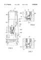
- FIG. 1is an elevational view of the system of the present invention for running of a casing liner downhole, with the launching manifold or container connected to a top drive, shown in full view, and the bypass or diverter sub, casing liner and guide shoe shown in section view;
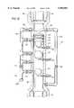
- FIG. 2is an enlarged view of the preferred embodiment of the launching manifold of FIG. 1 with the container shown in section view to better illustrate the releasable holders for the two balls and dart;
- FIG. 3is a section view taken along lines 3--3 of FIG. 2;
- FIG. 4is partial view of FIG. 2 rotated 90° to better illustrate the releasable dart holder
- FIG. 5is an elevation view of the preferred embodiment of the launching manifold as shown in FIG. 2, partially broken away, with hydraulic actuation shown, in solid lines, in the fluid flow position and, in phantom lines, in the dart actuation position;
- FIG. 6is an enlarged view of the broken away portion of FIG. 5 with the releasable dart holder shown in the dart actuation position;
- FIG. 7is a view similar to FIG. 6 with the dart sleeve shown sealed with the seat in the dart actuation position;
- FIG. 8is a view similar to FIG. 2 with the releasable dart holder and the dart sleeve shown in the dart actuation position so that drilling fluid can be received into the dart sleeve to move the dart down into the drill pipe;
- FIG. 9is a partial view of FIG. 8 rotated 90° to better illustrate the releasable dart holder and dart sleeve in the dart actuation position;
- FIG. 10is an enlarged view of an alternative embodiment of the launching manifold of FIG. 1 with the container shown in section view to better illustrate the releasable holders for the two balls and dart;
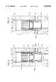
- FIG. 11is an enlarged detailed elevational view of the preferred embodiment of the bypass of the present invention, as shown in FIG. 1, in the open port position and positioned between a pipe and a casing liner;
- FIG. 12is a reduced scale elevational view of the bypass of the present invention, as shown in FIG. 11, with the smaller ball of FIGS. 2 or 10 positioned on the seat and the bypass sleeve moved to the closed port position;
- FIG. 13is an elevational view similar to FIG. 12 but with the ball blown past the seat of the fluid bypass and the increments of the seat shown fractured to allow the smaller ball to pass;
- FIG. 14is an enlarged detailed view of the preferred replaceable seat of the present invention and the smaller ball, as shown in FIG. 12, to better illustrate the molded grooves in the plastic frustoconical portion of the seat;
- FIG. 15is a view of the seat, as shown in FIG. 14, to better illustrate the fracturing of the seat by the smaller ball of FIG. 14 along the molded plastic grooves with the plastic being contained by the elastomer coating;
- FIG. 16is a view of the seat, as shown in FIG. 15, to better illustrate the additional incremental fracturing of the seat by the larger ball, as shown in FIGS. 2 or 10;
- FIG. 17is a view of the seat, as shown in FIG. 16 to better illustrate the full bore opening provided by the seat upon passage of the dart;
- FIG. 18is an elevational view of the larger ball, as shown in FIGS. 2 or 10, seating on the casing liner landing collar to allow required pressurization of the casing liner to activate a hydraulic casing liner hanger used to hang the casing liner to the casing;
- FIG. 19is an elevational view of cement being pushed by the drill pipe wiper dart down a drill pipe, the bypass of the present invention when in the closed port position, the casing liner and to the annulus between the casing liner and borehole after the casing liner landing collar ball seat has been sheared;
- FIG. 20is an elevational view of the drill pipe wiper dart after seating in the casing liner cement wiper plug, as shown in FIG. 19, with the drill pipe wiper dart moving with the casing liner cement wiper plug to further move the cement out of the casing liner into the annulus between the casing liner and the borehole;
- FIG. 21is an embodiment of the guide shoe, in a view similar to FIG. 1, where the present invention is used for rotating a casing liner having a guide shoe with teeth at its end for reaming rubble while washing the rubble up the annulus.
- FIGS. 1 and 20The preferred embodiment of the system and method of the present invention are illustrated in FIGS. 1 and 20, an application using a special guide shoe of the present invention is shown in FIG. 21.
- some of the components of the system of the present inventionare 1.) the launching manifold, generally indicated at 10, 2.) the bypass, generally indicated at 12, and 3.) the guide shoe, generally indicated at 14. While the mast M of FIG. 1 is illustrated on surface 16, the mast M could be located on an offshore rig, such as those disclosed, but not limited to, in U.S. Pat. Nos. 4,103,503; 4,916,999; 5,290,128; 5,388,930; and 5,419,657, assigned to the assignee of the present invention and incorporated by reference herein for all purposes.
- the mast Msuspends a traveling block B, which supports a top drive 18, such as manufactured by Varco B. J. Drilling Systems, that moves vertically on the TDS-65 block dolly D, as is known by those skilled in the art.
- An influent drilling fluid line Lconnects the drilling fluid reservoir (not shown) to the top drive 18.
- a kelly, a kelly bushing and a rotary tableare not shown, the launching manifold 10 is designed to alternatively be connected in that configuration for launching.
- the launching manifold 10can remain connected to the top drive 18 during the launching of both of the balls and dart while washing and reaming, as will be discussed below in detail.
- the bottom of the manifold 10is stabbed or threaded into a drill string, generally indicated at S, comprising a plurality of drill pipes P 1 , P 2 , P 3 .
- the number of pipes or stands of pipes usedwill, of course, depend on the depth of the well.
- the bypass 12is threadedly connected between the lowermost joint of pipe P 3 and the casing hanger CH, as will be discussed in detail below.
- the open guide shoe, generally indicated at 14,preferably does not have any float valve and includes multiple openings, is secured to the bottom of the casing liner 20.
- a device resulting from a Davis Type 505AF shoe with the flap removed and with multiple openings in its sideis used.
- other shoessuch as the Model 1390 float shoe with its valve removed and multiple openings in its side, distributed by Weatherford-Gemoco of Houma, La., could be used.
- the surface casing SCis encased by solidified cement CE 1 , in the formation F and includes an opening O adjacent its top for controlled return of drilling fluid from up the annulus between the pipe P 1 and the casing SC
- An intermediate casing liner C 2encased by solidified cement CE 2 in the formation F, is hung from the casing SC by either a mechanical or hydraulic hanger H.
- the casing liner 20includes a casing liner wiper plug 22 and a casing liner landing collar 24, that will be discussed below in detail.
- a preferred casing liner landing collar 24is a HS-SR (FIG. 502) landing collar, distributed by TIW of Houston, Tex.
- other collarssuch as the Model 1490 collar with its valve removed, distributed by Weatherford-Gemoco of Houma, La., could be used.
- the inside diameter of collar 24is approximately 2.6".
- the annulus A 1 between the pipe P 3 and the casing C 2is greater in area than the annulus A 2 between the casing liner 20 and the casing C 2 .
- the manifold 10includes a container, generally indicated at 28, having a top portion 28A threadedly connected to a bottom portion 28B.
- the container bottom portion 28Bis sized to receive a dart assembly, generally indicated at 29, including a jacket 30 having four equidistant spaced members 32A, 32B, 32C and 32D fixedly connected to a cylinder 34.
- Horizontal plate 36is removably positioned on shoulders of members 32A, 32B, 32C and 32D.
- the dart assembly 29is removable from the container bottom portion 28B by unthreading the top portion 28A from the bottom portion 28B and removing snap ring 38. The replaceability of the dart assembly 29 will reduce manufacture and inventory cost.
- cylinder 34has two vertical slots 34A, 34B to allow the dart sleeve 40 and pivotly attached U-shaped holding member 44 to slide up out of cylinder 34.
- a wiper dart 42is positioned in dart sleeve 40 to rest on the dart U-shaped holding member 44.
- the vertical slots 34A, 34Bprovide clearance for the U-shaped holding member 44 to slide out of cylinder 34.
- dart sleeve 40can then be moveably positioned between a fluid flow position, as shown in FIGS. 2, 4 and 5, and a dart actuation position, as shown in FIGS. 7, 8 and 9.
- a wiper dartthat could be used is the TIW pump down plug No. 2000.01 available from TIW Corporation of Houston, Tex.
- the container bottom portion 28Bfurther includes a replaceable soft seat 46 removably positioned on an upwardly facing shoulder in the bottom portion 28B. Though seat 46 is shown held in position by snap ring 48, preferably seat 46 is press fit into and press removed from bottom portion 28B, therefore, eliminating the need for snap ring 48.
- the container 28further includes a holding member, generally indicated at 50, for holding the smaller ball 52.
- the holding member 50includes an elastomer member 54 having a circular opening 54A sized to allow release of the ball 52 when urged by rod 56 connected to piston 58.
- the rod 56can be remotely pneumatically or hydraulically to urge the ball 52 to past the elastomer member 54 and down the pipe P 1 .
- a hammer(not shown) could be used to strike the end 58A to manually move the rod 56 inwardly.
- Threaded member 60is used to removably position the holding member 50 in the side of the container 28.
- a centering member 62is provided in holding member 50 to center the ball 52 relative to the rod 56 and opening 54A.
- a substantially identical holding memberis provided to hold a larger ball 66.
- the centering member 62is not needed since the holding member 64 is sized to center the larger ball 66 with its rod and the elastomer member 68 having a larger opening 68A sized for the larger ball 66.
- This interchangeability of the holder members 50 and 64will reduce inventory cost and allows reloading of each holding member with their respective balls.
- An annular member 70is shown connected into a channel 72 in the container bottom portion 28B and includes a plurality of equidistant shaped holes 74A, 74B (others not shown) for receiving threaded shafts 76A, 76B (others not shown).
- the shaftsare used with bolts to connect a bell guide 78 to the bottom of the launching manifold 10.
- the bell guide 78includes five (5) 5" openings 78A, 78B (other not shown) to allow visual inspection of the connection of the pipe P 1 with the expendable saver sub or nipple 80 used to connect the pipe P 1 to the launching manifold 10.
- the bell guide 78 and annular member 70could be removed, if desired, and the manifold 10 could be connected to a kelly (not shown), as would be now known to one skilled in the art.
- the bell guide 78has double conical sections. One section, as shown in FIG. 2, is connected with a second conical section having a lower angle to guide the drill pipe to center.
- the container top portion 28Aincludes a spring urged cement check valve assembly 82 threadedly connected in the side opening of the container 28.
- a cement line 84is releasable threaded to the assembly 82, preferably only during the cementing operation.
- each side of the container 28includes a hydraulic actuator 88A, 88B (not shown) to move corresponding arms 90A, 90B by pivotably connected pistons 88A', 88B' (not shown).
- the arm 90Arotates cam member 92A and its pin 94A.
- the pin 94Ais received in a slot 44A on one side of the U-shaped holding member 44, as best shown in FIG. 5.
- a lug 95Apivotly connects the sleeve 40 to the U-shaped holding member 44.
- the cylinder slots 34A, 34Balign the slots 44A, 44B on each side of the U-shaped holding member 44 with the pins 94A, 94B, when the sleeve 40 is slidably installed in the cylinder 34.
- the arm 90Ais pulled further downwardly by piston 88A', as shown in phantom view of FIG. 5. Since sleeve 40 is constrained from horizontal movement by cylinder 34, this further downwardly pulling of arm 90A and its pin 94A in slot 44A moves the lug 95A rigidly attached to sleeve 40 downwardly to seal the sleeve 40 with soft seat 46.
- the arm 90Buses similar linkage to provide corresponding forces on the opposing side of the U-shaped holding member 44 and sleeve 40.
- arms 90A, 90Bcould be disengaged from their respective cam members 92A, 92B and tools, such as pipe wrenches, attached to the outwardly extending rods 93A, 93B of the cam members 92A, 92B to manually rotate the cam members 92A, 92B thereby rotating the U-shaped holding member 44 out of way of dart 42 and pull sleeve 40 to seal with seat 46.
- toolssuch as pipe wrenches
- FIGS. 8 and 9the sleeve 40 has now been moved downwardly as shown, to simultaneously seal the sleeve with seat 46 and to open a flow path from passage 26 into sleeve chamber 98 to supply drilling fluid behind the dart 42. This drilling fluid urges the dart 42 out of the dart assembly 29, past nipple 80 and into pipe P 1 .
- the alternative launching manifold 10' of FIG. 1is shown threadedly connected between the top drive 18 and pipe P 1 of drill string S.
- the drilling fluid line Lprovides drilling fluid in passage PA that communicates with truncated bore 100 that, in turn, communicates both with a first flow line 102 having a first valve 104, and a second flow line 106 having a second and valves 108 and 110, respectively.
- a third flow line 112 having nipple 112Ais in communication with the second flow line 106, depending on whether valve 114 is in the open or closed position, and the container 116, if valve 117 is open or closed.
- the container 116 of the manifold 10'is sized to receive and releasably hold, from bottom to top, smaller ball 52, larger ball 66, and a drill pipe wiper dart 42 having outwardly and upwardly extending wiper cups 42' that have an outer diameter greater than either of the balls 52 and 66.
- the dart 42 of FIGS. 2 and 8are the preferred configuration of a dart to be used with the present invention, other dart configurations such as shown in FIGS. 10 and 17 could be used.
- the ball 52, ball 66 and dart 42, as shown in FIG. 10,are all in communication and axially aligned with the drill string S, and in particular pipe P 1 .
- the balls 52, 66are fabricated from drillable brass.
- Example of ball sizes usedare a 11/4" smaller ball 52 and a 1.75" larger ball 66.
- the ball 52, ball 66 and dart 42, respectivelyare released to fall by gravity into the pipe P 1 , assuming the rod(s) below it have been fully threaded outward to provide sufficient clearance for the consecutively larger ball 66 or dart 42.
- bypass 12is shown in the open port position and threadedly connected between the pipe P 3 and the casing liner hanger running tool.
- the casing liner hanger CHis connected below the casing liner hanger running tool, as is known by one of ordinary skill in the art.
- An adapter 12Ais shown for connection of the housing 124 of the bypass 12 to the casing liner hanger CH.
- the annulus A 2is smaller in area than annulus A 1 due to the larger outside diameter of the casing liner 20.
- the housing 124includes eight equidistant spaced flow ports 126A, 126B, 126C, 126D and 126E (others not shown), though any mixture of ports and port sizes could be used to provide the desired flow characteristics while maintaining the structural integrity of the housing 124 sufficient to withstand rotational forces for reaming, as will be discussed below.
- the sizing and material chosen for the housing 124provides a rotational and axial load capacity that is not a limitation to the drill string rotational and loading capacity. In one case, AISI 4140 qualified 130K(SI minimum yield material was used.
- the housing 124includes a first inside diameter 128 that is greater than the inside diameter P 3 ' of pipe P 3 .
- P 3 'is preferably equal to or less than the inside diameter 130 of the housing 124.
- the diameters 128 and 130define a blocking shoulder 132 for blocking downward movement of sleeve or cover 134.
- Sleeve 134includes an inside diameter 136 that is equal to diameters 130 and equal to or greater than diameter P 3 ' to provide a "full bore” opening through the housing 124, as will be described in detail below.
- the sleeve 134is shown with sixteen equidistant spaced and sized upwardly extending resilient fingers 136A, 136B, 136C, 136D, 136E, 136F, 136G and 136H (others not shown) each having an outwardly extending shoulder, such as shoulders 136A' and 136H', that are received in a first inwardly facing annular groove 138 in the housing 124 for maintaining the sleeve 134 in the open port position.
- the bypass 12further includes a seat 140 that is attached to the sleeve 134 on an upwardly facing shoulder 142 in the sleeve 134.
- a removable snap ring 144is used for securing the seat 140 during use while allowing replacement of the seat 140 after use in a run.
- a second lower inwardly facing annular groove 146is provided in the housing 124 and, preferably, has an o-ring 148 provided in this groove 146, as shown.
- a second shoulder 150is provided in the sleeve 134 for clearance of the seat 140 after its use to provide the "full bore” opening of the bypass 12, as will be discussed in detail below.
- the smaller ball 52is shown seated on seat 140 of sleeve 134 in the housing 124 of the bypass 12.
- the sleeve 134moves downwardly to the closed port position to close and seal off (using illustrated annular o-rings) all the flow ports, such as ports 126A and 126E.
- the force created by the pressurized drilling fluid acting on the ball 52forces the resilient finger shoulders, such as shoulders 136A' and 136H', inwardly and downwardly until the shoulders of all the fingers are received in the annular groove 146 to resist upward movement of the sleeve 134 after it has moved to the closed port position. Further downward movement of the sleeve 134 is blocked by engagement of the sleeve 134 with blocking shoulder 132.
- the smaller ball 52has been blown through the seat 140 upon application of a predetermined pressurized drilling fluid so as to yield or incrementally fracture the seat 140.
- the ball 52then drops into the casing liner 20 and through the liner wiper plug 22 and casing liner landing collar 24 and out the end of the guide shoe 14 into the borehole BH formed by the exposed formation EF.
- the balls or darthave seated and sealed with seat 140, an increase of pressure in the drilling fluid will be noted by the operator on the surface.
- a decrease in drilling fluid pressurewill be noted by the operator on the surface.
- the seat 140could include a flapper held in the closed position by a shear pin of a predetermined shear strength.
- a predetermined drilling fluid pressurebelow the pin shear strength, the sleeve 134 could be moved downwardly to the closed port position. Then at a higher predetermined drilling fluid pressure the pin could be sheared and the flapper swung out or dropped downhole out of the way.
- an enclosed or sealing position seatcould be blown open.
- the preferred embodiment of the seat 140includes a cylindrical portion, generally indicated at 152, and a 30° angled frustoconical portion, generally indicated at 154.
- the nonfractured inside diameter of the opening of the frustoconical seatis preferably 1" to 11/8".
- the seat 140is fabricated from two materials, a phenolic (plastic) component, and an elastomer, such as rubber, preferably a nitrile, coating component to encase the phenolic component.
- the frustoconical portion 154 of the seat 140includes a plurality of fracture lines, preferably grooves, molded into the plastic.
- the fracture linesinclude a plurality of vertical grooves 156 and a plurality of increasingly larger concentric horizontal grooves 158A, 158B, 158C and 158D to provide predetermined incremental breakaway fracture of the seat 140.
- perforationscould also be used as fracture lines.
- the failure pattern or linemay also include raised ribs, as well as grooves, so that fracture occurs and is arrested in a pre-determined fashion.
- the cylindrical portion 152presents a downwardly facing shoulder 160 at the juncture with the frustoconical portion 154. Shoulder 160 engages the upwardly facing shoulder 142 of sleeve 134.
- the phenolic (plastic) componentwhile providing the desired structural support, will provide a predictable failure point or fracture, so as not to damage the balls or dart blown through the seat, particularly the outwardly extending seal cups 42' on the dart 42, 2.) the elastomer coating will contain the loose incremental plastic pieces resulting from the fractures, 3.) the elastomer provides a soft frustoconical sealing surface used to initiate a seal, on the consecutively launched balls 52, 66 and dart 42 remaining after the previous incremental fracture.
- the larger ball 66can seal on the remaining frustoconical elastomer seat 154 after the ball 52 has been blown through so that sufficient pressure can be built up to blow the ball 66 through seat 140, as best shown in FIG. 16.
- the still larger outside diameter seal cups 42' of the dart 42can seal on the remaining frustoconical rubber seat 154 after the ball 66 has been blown through, so that sufficient pressure can be built up to blow the dart 42 through seat 140.
- the preferably 30° angled frustoconical portion 154has been incrementally fractured, as best shown in FIG. 17, to permit a substantially "full bore” opening through the housing 124 with minimum or no resistance.
- the fractured and vertical "frustoconical" portion 154can hang in the counterbore 162 between shoulders 150 and 142, as best shown in FIGS. 11 and 14.
- the seat 140can be fabricated from a low yield material such as a 1018 mild steel alloy with a 150 to 175 BHN (Brinell hardness number). While both the preferred and alternative embodiments can be split or fractured, any seat that would allow the balls 52, 66 and dart 42 to seal and then pass the housing 124 would be acceptable to practice the present invention. However, if a good seal is not achieved, as is known by those skilled in the art, the drilling fluid pumping could be increased until the ball or dart is blown through the seat.
- BHNBatteryll hardness number
- the ball 66has been dropped from the manifold 10, down the drill string S through pipe P 3 , blown through seat 140, as best shown in FIG. 16, through bypass 12, through casing liner wiper plug 22 to seat on casing liner landing collar 24. Pressure then is increased in casing liner 20 to actuate hydraulic casing liner hanger CH via casing liner hanger port 20A to hang the casing liner 20 on casing C 2 . Pressure is then raised higher to blow the shear pins 24A, 24B holding the conventional casing liner landing collar ball seat (not shown) in casing liner 20. The seat of collar 24 and ball 66 are then blown downhole past guide shoe 14 and in the bottom of borehole BH.
- a predetermined amount of cementflows through line 84 of manifold 10 and down the pipe P 1 .
- the dart 42is then released to allow it to fall down the container.
- drilling fluidis then pumped behind the dart 42 to move it down pipe P 3 , as shown in FIG. 19.
- the dart 42is then blown through seat 140 of the bypass 12 thereby incrementally fracturing the seat 140 to provide a "full bore” opening.
- the dart 42has engaged the casing liner wiper plug 22 and after sufficient drilling fluid pressure, shears the pins 22A and 22B, as best shown in FIGS. 19 and 20, and moves the wiper plug 22 down to the casing liner landing collar 24.
- the plug 22latches into the profile of the collar 24 thereby moving the cement CE 3 out into the annulus A 3 between the casing liner 20 and the exposed formation EF of the borehole BH.
- cementalso remains in the casing liner 20 between the elevation of the collar 24 and the guide shoe 14.
- the method of use of the system of the present invention including the manifold 10, bypass 12 and guide shoe 14, in combination with other existing componentsallows a casing liner 20 to be run downhole with reduced surge pressure, hanging of the casing liner 20 on the existing casing C 2 and cementing of the casing liner 20 in the borehole to be accomplished in a single trip of the drill string S downhole.
- the larger ball 66is then released from the manifold 10, again down through the string S and through the seat 140 resulting in additional incremental fractures to the seat 140, as best shown in FIG. 16, landing on the collar 24, as best shown in FIG. 18.
- the drilling fluidis pressurized so as to hydraulically set the hanger CH via port 20A, as shown in FIG. 18.
- the fluid pressurethen is further increased so that the shear pins 24A, 24B fail and the seat of collar 24 and ball 66 drop out of the casing liner 20 into the borehole BH.
- the cement CE 3 supplyis then connected via the flow line 84 and after pressure opens check valve assembly 82, cement CE 3 is pumped through the manifold 10 so that the cement CE 3 moves down the drill string S.
- the dart 42is then released, as described above, and drops onto the cement CE 3 .
- Drilling fluidis pumped behind the dart 42 to move the dart 42 downwardly thereby pushing the cement CE 3 down the string S, as shown in FIG. 19.
- the dart 42then moves through the seat 140 resulting in the full incremental fracturing of the seat 140, as shown in FIG. 17, and engages the wiper plug 22.
- the plug 22after failure of shear pins 22A, 22B, then is pushed by pressurized drilling fluid down the casing liner 20 thereby pushing the cement CE 3 up the annulus A 3 between the casing liner 20 and the borehole BH until the plug 22 is engaged in the collar 24 thereby permitting a normal cementing job of the casing liner 20 in the borehole BH, as best shown in FIG. 20.
- the systemprovides a method where a casing liner 20 can be run at a relatively higher rate of speed, even with tight clearances between the liner 20 and the casings SH, C 2 .
- the casing liner 20can then be hung from the casing C 2 , and cemented in the borehole BH all on a single trip downhole.
- the manifold 10does not require to be replaced with other manifolds or containers to launch balls and dart(s) but can perform all the steps of closing the port, hanging the liner 20 and cementing the liner 20 without replacement of or additions to the container.
- the inventionallows "full bore” opening through the housing 124 while providing structural integrity between the pipe P 3 and liner 20 to allow rotation.
- the manifold 10permits circulation of drilling fluid to the casing liner 20 when needed, such as shown in FIG. 21, for washing while reaming of a rubble zone RZ or other problematic borehole instabilities with a specially adapted guide shoe GS or 14' having teeth T thereon, as will be discussed below in detail.
- the "full bore” breakaway seat 140while allowing circulation through the casing liner 20 up the annuli A3, A2 and A1, also allows the larger ball 66 and dart 42 to pass through without damage.
- a borehole BH'was drilled from the previous 117/8" casing C 2 ' at 12100' MD/TVD to 13813' MD/TVD using a 105/8" by 121/4" DPI B1-Center bit.
- a 105/8" holewas drilled from 13813' to 14427' MD/TVD.
- the holewas enlarged to 143/4" (not shown) using an underreamer and sidewinders from 13700' to 14430' to make 3' of new hole from 14427' to 14430'.
- a 250 barrel pill of heavy drilling fluid (3 pounds per gallon higher than drilling fluid density used to drill interval)was placed in the wellbore prior to retrieving the drill string in order to run a casing liner.
- a total of 61 joints of 97/8" (9.875"), 62.8#, Q-125 STL casing 20'were run in a previous casing C 2 ' having an inside diameter of 10.711".
- the casing liner/casing clearancewas a total distance of 0.836" or 0.418" on each side of a centered annulus of the casing liner and casing.
- the casing liner and borehole clearancewas a total distance of 2.375" or 1.188" on each side of the centered annulus of the casing liner and borehole.
- a TIW No. 1718.02 1B-TC R ⁇ W/PIN TOP "HYDRO-HANGER" hydraulic casing liner hanger HGRwas run.
- the casing liner 20'was run into the hole BH' and the above described bypass 12' was attached to the top of the TIW casing liner hanger. Running speed of the casing liner 20' was limited to 1.5 minutes/stand to reduce surge pressure. The bypass 12' allowed full flow of fluid, therefore there was no excess time spent on the slips during connections. That is, there was no waiting for drilling fluids pressures to equalize so that the drilling fluid movement up the pipe would cease.
- the casing liner 20'tagged up at 14130' (approximate top of the rubble zone RZ).
- the bypass 12'allowed the liner 20' to be used to wash and ream from the beginning of the obstruction all the way to the desired setting depth of 14281'.
- the casing liner hanger HGRwas set and released and preparations for cementing were made.
- the casing liner 20'was able to be run with a minimum of time spent on the slips during connections (thus reducing the chances for differential sticking), the liner 20' was able to be used to wash and ream to bottom of the borehole BH" once problems were encountered, and circulation through the liner 20' was possible because it was not necessary to set it on bottom to close the bypass 12'. Circulation was established and the liner 20' was cemented in place using normal cementation methods. However, in this run no wiper plug was used. Instead, the cement was displaced down the pipe using a Halliburton rubber ball and the cement was displaced out of the casing liner based on volumetrics.
Landscapes
- Engineering & Computer Science (AREA)
- Life Sciences & Earth Sciences (AREA)
- Geology (AREA)
- Mining & Mineral Resources (AREA)
- Physics & Mathematics (AREA)
- Environmental & Geological Engineering (AREA)
- Fluid Mechanics (AREA)
- General Life Sciences & Earth Sciences (AREA)
- Geochemistry & Mineralogy (AREA)
- Mechanical Engineering (AREA)
- Earth Drilling (AREA)
- Control Of Fluid Pressure (AREA)
Abstract
Description
Claims (61)
Priority Applications (5)
| Application Number | Priority Date | Filing Date | Title |
|---|---|---|---|
| US08/837,772US5960881A (en) | 1997-04-22 | 1997-04-22 | Downhole surge pressure reduction system and method of use |
| PCT/US1998/008222WO1998048143A1 (en) | 1997-04-22 | 1998-04-22 | Downhole surge pressure reduction system and method of use |
| EP98918649AEP0991847A4 (en) | 1997-04-22 | 1998-04-22 | Downhole surge pressure reduction system and method of use |
| AU71536/98AAU752337B2 (en) | 1997-04-22 | 1998-04-22 | Downhole surge pressure reduction system and method of use |
| CA002288103ACA2288103C (en) | 1997-04-22 | 1998-04-22 | Downhole surge pressure reduction system and method of use |
Applications Claiming Priority (1)
| Application Number | Priority Date | Filing Date | Title |
|---|---|---|---|
| US08/837,772US5960881A (en) | 1997-04-22 | 1997-04-22 | Downhole surge pressure reduction system and method of use |
Publications (1)
| Publication Number | Publication Date |
|---|---|
| US5960881Atrue US5960881A (en) | 1999-10-05 |
Family
ID=25275372
Family Applications (1)
| Application Number | Title | Priority Date | Filing Date |
|---|---|---|---|
| US08/837,772Expired - LifetimeUS5960881A (en) | 1997-04-22 | 1997-04-22 | Downhole surge pressure reduction system and method of use |
Country Status (5)
| Country | Link |
|---|---|
| US (1) | US5960881A (en) |
| EP (1) | EP0991847A4 (en) |
| AU (1) | AU752337B2 (en) |
| CA (1) | CA2288103C (en) |
| WO (1) | WO1998048143A1 (en) |
Cited By (249)
| Publication number | Priority date | Publication date | Assignee | Title |
|---|---|---|---|---|
| US6082459A (en)* | 1998-06-29 | 2000-07-04 | Halliburton Energy Services, Inc. | Drill string diverter apparatus and method |
| US6182766B1 (en) | 1999-05-28 | 2001-02-06 | Halliburton Energy Services, Inc. | Drill string diverter apparatus and method |
| US6311775B1 (en)* | 2000-04-03 | 2001-11-06 | Jerry P. Allamon | Pumpdown valve plug assembly for liner cementing system |
| US6390200B1 (en) | 2000-02-04 | 2002-05-21 | Allamon Interest | Drop ball sub and system of use |
| US6431626B1 (en)* | 1999-04-09 | 2002-08-13 | Frankis Casing Crew And Rental Tools, Inc. | Tubular running tool |
| US6464008B1 (en) | 2001-04-25 | 2002-10-15 | Baker Hughes Incorporated | Well completion method and apparatus |
| WO2002097234A1 (en)* | 2001-05-18 | 2002-12-05 | Dril-Quip, Inc. | Line hanger, running tool and method |
| US6491103B2 (en) | 2001-04-09 | 2002-12-10 | Jerry P. Allamon | System for running tubular members |
| US20030024701A1 (en)* | 2001-08-03 | 2003-02-06 | Smith International, Inc. | Cementing manifold assembly |
| US6520257B2 (en) | 2000-12-14 | 2003-02-18 | Jerry P. Allamon | Method and apparatus for surge reduction |
| US6571869B1 (en) | 2000-03-13 | 2003-06-03 | Weatherford/Lamb, Inc. | Downhole surge pressure reduction and filtering apparatus |
| US6571876B2 (en) | 2001-05-24 | 2003-06-03 | Halliburton Energy Services, Inc. | Fill up tool and mud saver for top drives |
| US6575238B1 (en)* | 2001-05-18 | 2003-06-10 | Dril-Quip, Inc. | Ball and plug dropping head |
| US20030127227A1 (en)* | 2001-11-19 | 2003-07-10 | Packers Plus Energy Services Inc. | Method and apparatus for wellbore fluid treatment |
| WO2003064810A1 (en)* | 2002-01-31 | 2003-08-07 | Weatherford/Lamb, Inc. | Plug-dropping container for releasing a plug into a wellbore |
| US6634428B2 (en) | 2001-05-03 | 2003-10-21 | Baker Hughes Incorporated | Delayed opening ball seat |
| US6651743B2 (en) | 2001-05-24 | 2003-11-25 | Halliburton Energy Services, Inc. | Slim hole stage cementer and method |
| WO2003102367A1 (en)* | 2002-05-29 | 2003-12-11 | Weatherford/Lamb, Inc. | Method and apparatus to reduce downhole surge pressure using hydrostatic valve |
| US20040000406A1 (en)* | 2002-07-01 | 2004-01-01 | Allamon Jerry P. | Downhole surge reduction method and apparatus |
| US6695066B2 (en)* | 2002-01-18 | 2004-02-24 | Allamon Interests | Surge pressure reduction apparatus with volume compensation sub and method for use |
| US20040055741A1 (en)* | 2002-01-31 | 2004-03-25 | Weatherford/Lamb, Inc. | Plug-dropping container for releasing a plug into a wellbore |
| US6715541B2 (en) | 2002-02-21 | 2004-04-06 | Weatherford/Lamb, Inc. | Ball dropping assembly |
| WO2004031533A2 (en) | 2002-09-24 | 2004-04-15 | Baker Hughes Incorporated | Downhole ball dropping apparatus |
| US6729393B2 (en) | 2000-03-30 | 2004-05-04 | Baker Hughes Incorporated | Zero drill completion and production system |
| US20040108109A1 (en)* | 2002-12-10 | 2004-06-10 | Allamon Jerry P. | Drop ball catcher apparatus |
| US6752209B2 (en) | 2001-10-01 | 2004-06-22 | Bj Services Company | Cementing system and method for wellbores |
| US6776228B2 (en) | 2002-02-21 | 2004-08-17 | Weatherford/Lamb, Inc. | Ball dropping assembly |
| US6810958B2 (en) | 2001-12-20 | 2004-11-02 | Halliburton Energy Services, Inc. | Circulating cementing collar and method |
| US20040216883A1 (en)* | 2002-04-17 | 2004-11-04 | Anthony Allen | Fluid flow switching device |
| US6866100B2 (en) | 2002-08-23 | 2005-03-15 | Weatherford/Lamb, Inc. | Mechanically opened ball seat and expandable ball seat |
| US20050082054A1 (en)* | 2001-11-06 | 2005-04-21 | Den Boer Johannis J. | Gel release device |
| US20050183892A1 (en)* | 2004-02-19 | 2005-08-25 | Oldham Jack T. | Casing and liner drilling bits, cutting elements therefor, and methods of use |
| US20050257933A1 (en)* | 2004-05-20 | 2005-11-24 | Bernd-Georg Pietras | Casing running head |
| US20060011354A1 (en)* | 2004-07-16 | 2006-01-19 | Logiudice Michael | Surge reduction bypass valve |
| GB2416791A (en)* | 2004-07-30 | 2006-02-08 | Weatherford Lamb | Top drive system with access tool, ball or plug launching tool, or cementing tool |
| US20060070771A1 (en)* | 2004-02-19 | 2006-04-06 | Mcclain Eric E | Earth boring drill bits with casing component drill out capability and methods of use |
| US20060118295A1 (en)* | 2004-12-03 | 2006-06-08 | Rogers Henry E | Diverter tool |
| US20060118336A1 (en)* | 2004-12-03 | 2006-06-08 | Rogers Henry E | Diverter tool |
| US7069991B2 (en) | 2003-01-09 | 2006-07-04 | Weatherford/Lamb, Inc. | Method and apparatus for surge pressure reduction in a tool with fluid motivator |
| US7073598B2 (en) | 2001-05-17 | 2006-07-11 | Weatherford/Lamb, Inc. | Apparatus and methods for tubular makeup interlock |
| US7083005B2 (en) | 2002-12-13 | 2006-08-01 | Weatherford/Lamb, Inc. | Apparatus and method of drilling with casing |
| US7090023B2 (en) | 2002-10-11 | 2006-08-15 | Weatherford/Lamb, Inc. | Apparatus and methods for drilling with casing |
| US7090021B2 (en) | 1998-08-24 | 2006-08-15 | Bernd-Georg Pietras | Apparatus for connecting tublars using a top drive |
| US7093675B2 (en) | 2000-08-01 | 2006-08-22 | Weatherford/Lamb, Inc. | Drilling method |
| US7100710B2 (en) | 1994-10-14 | 2006-09-05 | Weatherford/Lamb, Inc. | Methods and apparatus for cementing drill strings in place for one pass drilling and completion of oil and gas wells |
| US7108084B2 (en) | 1994-10-14 | 2006-09-19 | Weatherford/Lamb, Inc. | Methods and apparatus for cementing drill strings in place for one pass drilling and completion of oil and gas wells |
| US7117957B2 (en) | 1998-12-22 | 2006-10-10 | Weatherford/Lamb, Inc. | Methods for drilling and lining a wellbore |
| US7128161B2 (en) | 1998-12-24 | 2006-10-31 | Weatherford/Lamb, Inc. | Apparatus and methods for facilitating the connection of tubulars using a top drive |
| US7128154B2 (en) | 2003-01-30 | 2006-10-31 | Weatherford/Lamb, Inc. | Single-direction cementing plug |
| US7131505B2 (en) | 2002-12-30 | 2006-11-07 | Weatherford/Lamb, Inc. | Drilling with concentric strings of casing |
| US7137454B2 (en) | 1998-07-22 | 2006-11-21 | Weatherford/Lamb, Inc. | Apparatus for facilitating the connection of tubulars using a top drive |
| US7140445B2 (en) | 1997-09-02 | 2006-11-28 | Weatherford/Lamb, Inc. | Method and apparatus for drilling with casing |
| US20060272824A1 (en)* | 2005-06-01 | 2006-12-07 | Adams Richard W | Downhole flapper circulation tool |
| US7147068B2 (en) | 1994-10-14 | 2006-12-12 | Weatherford / Lamb, Inc. | Methods and apparatus for cementing drill strings in place for one pass drilling and completion of oil and gas wells |
| EP1712730A3 (en)* | 2001-05-18 | 2006-12-27 | Dril-Quip, Inc. | Liner hanger, running tool and method |
| US7165634B2 (en) | 1994-10-14 | 2007-01-23 | Weatherford/Lamb, Inc. | Method and apparatus for cementing drill strings in place for one pass drilling and completion of oil and gas wells |
| US20070017679A1 (en)* | 2005-06-30 | 2007-01-25 | Wolf John C | Downhole multi-action jetting tool |
| US7188687B2 (en) | 1998-12-22 | 2007-03-13 | Weatherford/Lamb, Inc. | Downhole filter |
| US20070056722A1 (en)* | 2005-07-19 | 2007-03-15 | Tesco Corporation | Wireline entry sub |
| US7191840B2 (en) | 2003-03-05 | 2007-03-20 | Weatherford/Lamb, Inc. | Casing running and drilling system |
| AU2005225147B2 (en)* | 2000-03-13 | 2007-03-29 | Weatherford Technology Holdings, Llc | Downhole Surge Pressure Reduction and Filtering Apparatus |
| US20070079995A1 (en)* | 2004-02-19 | 2007-04-12 | Mcclain Eric E | Cutting elements configured for casing component drillout and earth boring drill bits including same |
| US7213656B2 (en) | 1998-12-24 | 2007-05-08 | Weatherford/Lamb, Inc. | Apparatus and method for facilitating the connection of tubulars using a top drive |
| US7216727B2 (en) | 1999-12-22 | 2007-05-15 | Weatherford/Lamb, Inc. | Drilling bit for drilling while running casing |
| US7219730B2 (en) | 2002-09-27 | 2007-05-22 | Weatherford/Lamb, Inc. | Smart cementing systems |
| US7219744B2 (en) | 1998-08-24 | 2007-05-22 | Weatherford/Lamb, Inc. | Method and apparatus for connecting tubulars using a top drive |
| US7228901B2 (en) | 1994-10-14 | 2007-06-12 | Weatherford/Lamb, Inc. | Method and apparatus for cementing drill strings in place for one pass drilling and completion of oil and gas wells |
| US7252152B2 (en) | 2003-06-18 | 2007-08-07 | Weatherford/Lamb, Inc. | Methods and apparatus for actuating a downhole tool |
| US7264067B2 (en) | 2003-10-03 | 2007-09-04 | Weatherford/Lamb, Inc. | Method of drilling and completing multiple wellbores inside a single caisson |
| US7303022B2 (en) | 2002-10-11 | 2007-12-04 | Weatherford/Lamb, Inc. | Wired casing |
| US7311148B2 (en) | 1999-02-25 | 2007-12-25 | Weatherford/Lamb, Inc. | Methods and apparatus for wellbore construction and completion |
| US7325610B2 (en) | 2000-04-17 | 2008-02-05 | Weatherford/Lamb, Inc. | Methods and apparatus for handling and drilling with tubulars or casing |
| WO2007136978A3 (en)* | 2006-05-02 | 2008-02-21 | Mako Rentals Inc | Dropping sub method and apparatus |
| US7334650B2 (en) | 2000-04-13 | 2008-02-26 | Weatherford/Lamb, Inc. | Apparatus and methods for drilling a wellbore using casing |
| US7360594B2 (en) | 2003-03-05 | 2008-04-22 | Weatherford/Lamb, Inc. | Drilling with casing latch |
| US20080093080A1 (en)* | 2006-10-19 | 2008-04-24 | Palmer Larry T | Ball drop circulation valve |
| US20080099196A1 (en)* | 1996-10-04 | 2008-05-01 | Latiolais Burney J | Casing make-up and running tool adapted for fluid and cement control |
| US7367391B1 (en) | 2006-12-28 | 2008-05-06 | Baker Hughes Incorporated | Liner anchor for expandable casing strings and method of use |
| US7370707B2 (en) | 2003-04-04 | 2008-05-13 | Weatherford/Lamb, Inc. | Method and apparatus for handling wellbore tubulars |
| US20080149336A1 (en)* | 2006-12-22 | 2008-06-26 | Halliburton Energy Services | Multiple Bottom Plugs for Cementing Operations |
| US7413020B2 (en) | 2003-03-05 | 2008-08-19 | Weatherford/Lamb, Inc. | Full bore lined wellbores |
| US20080196904A1 (en)* | 2007-01-12 | 2008-08-21 | Tesco Corporation | Wireline entry sub |
| US20080202751A1 (en)* | 1996-10-04 | 2008-08-28 | Frank's International, Inc. | Methods and Devices for Forming a Wellbore with Casing |
| US20080217025A1 (en)* | 2007-03-09 | 2008-09-11 | Baker Hughes Incorporated | Deformable ball seat and method |
| US20080230216A1 (en)* | 2005-07-19 | 2008-09-25 | Tesco Corporation | Wireline Entry Sub |
| US20080271884A1 (en)* | 2006-05-02 | 2008-11-06 | Mako Rentals, Inc. | Dropping sub method and apparatus |
| US7448456B2 (en) | 2002-07-29 | 2008-11-11 | Weatherford/Lamb, Inc. | Adjustable rotating guides for spider or elevator |
| US20080283244A1 (en)* | 2007-05-16 | 2008-11-20 | Gulfstream Services, Inc. | Method and apparatus for dropping a pump down plug or ball |
| US20080283251A1 (en)* | 2007-05-16 | 2008-11-20 | Phil Barbee | Method and apparatus for dropping a pump down plug or ball |
| US20090008098A1 (en)* | 2007-07-05 | 2009-01-08 | Barbee Jr John Phillip | Method and apparatus for catching a pump-down plug or ball |
| US20090044949A1 (en)* | 2007-08-13 | 2009-02-19 | King James G | Deformable ball seat |
| US20090044948A1 (en)* | 2007-08-13 | 2009-02-19 | Avant Marcus A | Ball seat having ball support member |
| US20090044946A1 (en)* | 2007-08-13 | 2009-02-19 | Thomas Schasteen | Ball seat having fluid activated ball support |
| US20090044955A1 (en)* | 2007-08-13 | 2009-02-19 | King James G | Reusable ball seat having ball support member |
| US7509722B2 (en) | 1997-09-02 | 2009-03-31 | Weatherford/Lamb, Inc. | Positioning and spinning device |
| RU2352767C2 (en)* | 2003-06-24 | 2009-04-20 | Бейкер Хьюз Инкорпорейтед | Facility for control over flow with extruded gate |
| US20090159297A1 (en)* | 2007-12-21 | 2009-06-25 | Schlumberger Technology Corporation | Ball dropping assembly and technique for use in a well |
| US20090277637A1 (en)* | 2008-05-09 | 2009-11-12 | Gulfstream Services, Inc., A Corporation Created And Existing Under The Laws Of The State Of Louisi | Oil well plug and abandonment method |
| US7617866B2 (en) | 1998-08-24 | 2009-11-17 | Weatherford/Lamb, Inc. | Methods and apparatus for connecting tubulars using a top drive |
| US7621351B2 (en) | 2006-05-15 | 2009-11-24 | Baker Hughes Incorporated | Reaming tool suitable for running on casing or liner |
| US7650944B1 (en) | 2003-07-11 | 2010-01-26 | Weatherford/Lamb, Inc. | Vessel for well intervention |
| US7669662B2 (en) | 1998-08-24 | 2010-03-02 | Weatherford/Lamb, Inc. | Casing feeder |
| US20100051350A1 (en)* | 2004-02-19 | 2010-03-04 | Baker Hughes Incorporated | Drilling out casing bits with other casing bits |
| US20100084145A1 (en)* | 2008-10-07 | 2010-04-08 | Greg Giem | Multiple Activation-Device Launcher For A Cementing Head |
| US7694744B2 (en) | 2005-01-12 | 2010-04-13 | Weatherford/Lamb, Inc. | One-position fill-up and circulating tool and method |
| US20100089594A1 (en)* | 2007-05-16 | 2010-04-15 | Phil Barbee | Method and apparatus for dropping a pump down plug or ball |
| US7712523B2 (en) | 2000-04-17 | 2010-05-11 | Weatherford/Lamb, Inc. | Top drive casing system |
| US7757759B2 (en) | 2006-04-27 | 2010-07-20 | Weatherford/Lamb, Inc. | Torque sub for use with top drive |
| US20100187011A1 (en)* | 2007-10-02 | 2010-07-29 | Jurica Chad T | Cutting structures for casing component drillout and earth-boring drill bits including same |
| WO2010085617A1 (en)* | 2009-01-22 | 2010-07-29 | Blackhawk Specialty Tools, Llc | Method and apparatus for performing cementing operations |
| US20100282338A1 (en)* | 2009-05-07 | 2010-11-11 | Baker Hughes Incorporated | Selectively movable seat arrangement and method |
| US20100294511A1 (en)* | 2009-05-20 | 2010-11-25 | Colin David Winzer | Down-hole actuation device storage apparatus and method for launching |
| US20100294515A1 (en)* | 2009-05-22 | 2010-11-25 | Baker Hughes Incorporated | Selective plug and method |
| US20100294514A1 (en)* | 2009-05-22 | 2010-11-25 | Baker Hughes Incorporated | Selective plug and method |
| US7845418B2 (en) | 2005-01-18 | 2010-12-07 | Weatherford/Lamb, Inc. | Top drive torque booster |
| US20100314126A1 (en)* | 2009-06-10 | 2010-12-16 | Baker Hughes Incorporated | Seat apparatus and method |
| US20110011597A1 (en)* | 2009-07-15 | 2011-01-20 | Baker Hughes Incorporated | Tubular valve system and method |
| US7874352B2 (en) | 2003-03-05 | 2011-01-25 | Weatherford/Lamb, Inc. | Apparatus for gripping a tubular on a drilling rig |
| US7882902B2 (en) | 2006-11-17 | 2011-02-08 | Weatherford/Lamb, Inc. | Top drive interlock |
| US20110030975A1 (en)* | 2009-08-04 | 2011-02-10 | Baker Hughes Incorporated | Tubular system with selectively engagable sleeves and method |
| US20110030976A1 (en)* | 2009-08-10 | 2011-02-10 | Baker Hughes Incorporated | Tubular actuator, system and method |
| US20110030968A1 (en)* | 2009-08-10 | 2011-02-10 | Baker Hughes Incorporated | Tubular actuator, system and method |
| US20110036592A1 (en)* | 2009-08-13 | 2011-02-17 | Baker Hughes Incorporated | Tubular valving system and method |
| US20110048712A1 (en)* | 2009-08-27 | 2011-03-03 | Phil Barbee | Method and apparatus for dropping a pump down plug or ball |
| US20110067888A1 (en)* | 2009-09-22 | 2011-03-24 | Baker Hughes Incorporated | Plug counter and method |
| US20110073321A1 (en)* | 2009-09-25 | 2011-03-31 | Baker Hughes Incorporated | Tubular actuator and method |
| US20110073320A1 (en)* | 2009-09-25 | 2011-03-31 | Baker Hughes Incorporated | Tubular actuator and method |
| US20110100647A1 (en)* | 2009-10-29 | 2011-05-05 | Baker Hughes Incorporated | Tubular Actuator, System and Method |
| US7954571B2 (en) | 2007-10-02 | 2011-06-07 | Baker Hughes Incorporated | Cutting structures for casing component drillout and earth-boring drill bits including same |
| US20110174505A1 (en)* | 2010-01-21 | 2011-07-21 | Smith International, Inc. | Ball drop module |
| US20110192607A1 (en)* | 2010-02-08 | 2011-08-11 | Raymond Hofman | Downhole Tool With Expandable Seat |
| US20110232923A1 (en)* | 2007-05-16 | 2011-09-29 | Gulfstream Services, Inc. | Method and apparatus for dropping a pump down plug or ball |
| EP2378056A2 (en) | 2010-04-16 | 2011-10-19 | Weatherford Lamb, Inc. | Drilling fluid pressure control system for a floating rig |
| USRE42877E1 (en) | 2003-02-07 | 2011-11-01 | Weatherford/Lamb, Inc. | Methods and apparatus for wellbore construction and completion |
| US20120205121A1 (en)* | 2011-02-10 | 2012-08-16 | Halliburton Energy Services, Inc. | System and method for servicing a wellbore |
| US8297358B2 (en) | 2010-07-16 | 2012-10-30 | Baker Hughes Incorporated | Auto-production frac tool |
| US8322432B2 (en) | 2009-01-15 | 2012-12-04 | Weatherford/Lamb, Inc. | Subsea internal riser rotating control device system and method |
| US8327931B2 (en) | 2009-12-08 | 2012-12-11 | Baker Hughes Incorporated | Multi-component disappearing tripping ball and method for making the same |
| US8347983B2 (en) | 2009-07-31 | 2013-01-08 | Weatherford/Lamb, Inc. | Drilling with a high pressure rotating control device |
| US20130068484A1 (en)* | 2002-08-21 | 2013-03-21 | Packers Plus Energy Services Inc. | Method and apparatus for wellbore fluid treatment |
| US8424610B2 (en) | 2010-03-05 | 2013-04-23 | Baker Hughes Incorporated | Flow control arrangement and method |
| US8425651B2 (en) | 2010-07-30 | 2013-04-23 | Baker Hughes Incorporated | Nanomatrix metal composite |
| US8479808B2 (en) | 2011-06-01 | 2013-07-09 | Baker Hughes Incorporated | Downhole tools having radially expandable seat member |
| US20130233535A1 (en)* | 2012-03-08 | 2013-09-12 | Halliburton Energy Services, Inc. | Interlocking segmented seat for downhole wellbore tools |
| US8561700B1 (en) | 2009-05-21 | 2013-10-22 | John Phillip Barbee, Jr. | Method and apparatus for cementing while running casing in a well bore |
| US8573295B2 (en) | 2010-11-16 | 2013-11-05 | Baker Hughes Incorporated | Plug and method of unplugging a seat |
| US8631876B2 (en) | 2011-04-28 | 2014-01-21 | Baker Hughes Incorporated | Method of making and using a functionally gradient composite tool |
| US8636073B2 (en) | 2010-04-05 | 2014-01-28 | Arthur Keith McNeilly | Segmented ball seat assembly valve |
| US8662178B2 (en) | 2011-09-29 | 2014-03-04 | Halliburton Energy Services, Inc. | Responsively activated wellbore stimulation assemblies and methods of using the same |
| US20140060848A1 (en)* | 2011-08-31 | 2014-03-06 | The Subsea Company | Plug and Pressure Testing Method and Apparatus |
| US8668006B2 (en) | 2011-04-13 | 2014-03-11 | Baker Hughes Incorporated | Ball seat having ball support member |
| US8668018B2 (en) | 2011-03-10 | 2014-03-11 | Baker Hughes Incorporated | Selective dart system for actuating downhole tools and methods of using same |
| US8668016B2 (en) | 2009-08-11 | 2014-03-11 | Halliburton Energy Services, Inc. | System and method for servicing a wellbore |
| US8668013B2 (en) | 2010-08-24 | 2014-03-11 | Baker Hughes Incorporated | Plug counter, fracing system and method |
| US8695710B2 (en) | 2011-02-10 | 2014-04-15 | Halliburton Energy Services, Inc. | Method for individually servicing a plurality of zones of a subterranean formation |
| US8776884B2 (en) | 2010-08-09 | 2014-07-15 | Baker Hughes Incorporated | Formation treatment system and method |
| US8783365B2 (en) | 2011-07-28 | 2014-07-22 | Baker Hughes Incorporated | Selective hydraulic fracturing tool and method thereof |
| US8844652B2 (en) | 2007-10-23 | 2014-09-30 | Weatherford/Lamb, Inc. | Interlocking low profile rotating control device |
| US8869898B2 (en) | 2011-05-17 | 2014-10-28 | Baker Hughes Incorporated | System and method for pinpoint fracturing initiation using acids in open hole wellbores |
| US8887818B1 (en) | 2011-11-02 | 2014-11-18 | Diamondback Industries, Inc. | Composite frac plug |
| US8893811B2 (en) | 2011-06-08 | 2014-11-25 | Halliburton Energy Services, Inc. | Responsively activated wellbore stimulation assemblies and methods of using the same |
| US8899334B2 (en) | 2011-08-23 | 2014-12-02 | Halliburton Energy Services, Inc. | System and method for servicing a wellbore |
| US20140352968A1 (en)* | 2013-06-03 | 2014-12-04 | Cameron International Corporation | Multi-well simultaneous fracturing system |
| US20150068772A1 (en)* | 2013-09-10 | 2015-03-12 | Halliburton Energy Services, Inc. | Downhole Ball Dropping Systems and Methods with Redundant Ball Dropping Capability |
| US20150068771A1 (en)* | 2013-09-10 | 2015-03-12 | Halliburton Energy Services, Inc. | Downhole Ball Dropping Systems and Methods |
| US8991509B2 (en) | 2012-04-30 | 2015-03-31 | Halliburton Energy Services, Inc. | Delayed activation activatable stimulation assembly |
| US9004091B2 (en) | 2011-12-08 | 2015-04-14 | Baker Hughes Incorporated | Shape-memory apparatuses for restricting fluid flow through a conduit and methods of using same |
| US9004181B2 (en) | 2007-10-23 | 2015-04-14 | Weatherford/Lamb, Inc. | Low profile rotating control device |
| US9016388B2 (en) | 2012-02-03 | 2015-04-28 | Baker Hughes Incorporated | Wiper plug elements and methods of stimulating a wellbore environment |
| US9022107B2 (en) | 2009-12-08 | 2015-05-05 | Baker Hughes Incorporated | Dissolvable tool |
| US9033055B2 (en) | 2011-08-17 | 2015-05-19 | Baker Hughes Incorporated | Selectively degradable passage restriction and method |
| US20150136403A1 (en)* | 2013-11-20 | 2015-05-21 | CNPC USA Corp. | Ball seat system |
| US9057242B2 (en) | 2011-08-05 | 2015-06-16 | Baker Hughes Incorporated | Method of controlling corrosion rate in downhole article, and downhole article having controlled corrosion rate |
| US9068428B2 (en) | 2012-02-13 | 2015-06-30 | Baker Hughes Incorporated | Selectively corrodible downhole article and method of use |
| US9080098B2 (en) | 2011-04-28 | 2015-07-14 | Baker Hughes Incorporated | Functionally gradient composite article |
| US9079246B2 (en) | 2009-12-08 | 2015-07-14 | Baker Hughes Incorporated | Method of making a nanomatrix powder metal compact |
| US9090956B2 (en) | 2011-08-30 | 2015-07-28 | Baker Hughes Incorporated | Aluminum alloy powder metal compact |
| US9090955B2 (en) | 2010-10-27 | 2015-07-28 | Baker Hughes Incorporated | Nanomatrix powder metal composite |
| US9101978B2 (en) | 2002-12-08 | 2015-08-11 | Baker Hughes Incorporated | Nanomatrix powder metal compact |
| US9109429B2 (en) | 2002-12-08 | 2015-08-18 | Baker Hughes Incorporated | Engineered powder compact composite material |
| US9109269B2 (en) | 2011-08-30 | 2015-08-18 | Baker Hughes Incorporated | Magnesium alloy powder metal compact |
| US9127515B2 (en) | 2010-10-27 | 2015-09-08 | Baker Hughes Incorporated | Nanomatrix carbon composite |
| US9133695B2 (en) | 2011-09-03 | 2015-09-15 | Baker Hughes Incorporated | Degradable shaped charge and perforating gun system |
| US9139928B2 (en) | 2011-06-17 | 2015-09-22 | Baker Hughes Incorporated | Corrodible downhole article and method of removing the article from downhole environment |
| US9145758B2 (en) | 2011-06-09 | 2015-09-29 | Baker Hughes Incorporated | Sleeved ball seat |
| US9163470B2 (en) | 2008-10-07 | 2015-10-20 | Schlumberger Technology Corporation | Multiple activation-device launcher for a cementing head |
| US9175542B2 (en) | 2010-06-28 | 2015-11-03 | Weatherford/Lamb, Inc. | Lubricating seal for use with a tubular |
| US9187990B2 (en) | 2011-09-03 | 2015-11-17 | Baker Hughes Incorporated | Method of using a degradable shaped charge and perforating gun system |
| US9227243B2 (en) | 2009-12-08 | 2016-01-05 | Baker Hughes Incorporated | Method of making a powder metal compact |
| US9234406B2 (en) | 2012-05-09 | 2016-01-12 | Utex Industries, Inc. | Seat assembly with counter for isolating fracture zones in a well |
| US9243475B2 (en) | 2009-12-08 | 2016-01-26 | Baker Hughes Incorporated | Extruded powder metal compact |
| US9267347B2 (en) | 2009-12-08 | 2016-02-23 | Baker Huges Incorporated | Dissolvable tool |
| US9273526B2 (en) | 2013-01-16 | 2016-03-01 | Baker Hughes Incorporated | Downhole anchoring systems and methods of using same |
| US9284812B2 (en) | 2011-11-21 | 2016-03-15 | Baker Hughes Incorporated | System for increasing swelling efficiency |
| US9316084B2 (en) | 2011-12-14 | 2016-04-19 | Utex Industries, Inc. | Expandable seat assembly for isolating fracture zones in a well |
| US9347119B2 (en) | 2011-09-03 | 2016-05-24 | Baker Hughes Incorporated | Degradable high shock impedance material |
| US9359853B2 (en) | 2009-01-15 | 2016-06-07 | Weatherford Technology Holdings, Llc | Acoustically controlled subsea latching and sealing system and method for an oilfield device |
| CN105793516A (en)* | 2013-12-04 | 2016-07-20 | 哈里伯顿能源服务公司 | Ball drop tool and methods of use |
| US9435168B2 (en) | 2013-02-03 | 2016-09-06 | National Oilwell DHT, L.P. | Downhole activation assembly and method of using same |
| US9534469B2 (en) | 2013-09-27 | 2017-01-03 | Baker Hughes Incorporated | Stacked tray ball dropper for subterranean fracking operations |
| US9556704B2 (en) | 2012-09-06 | 2017-01-31 | Utex Industries, Inc. | Expandable fracture plug seat apparatus |
| US20170051575A1 (en)* | 2014-08-15 | 2017-02-23 | Thru Tubing Solutions, Inc. | Flapper valve tool |
| US9605508B2 (en) | 2012-05-08 | 2017-03-28 | Baker Hughes Incorporated | Disintegrable and conformable metallic seal, and method of making the same |
| US9611713B2 (en) | 2013-03-12 | 2017-04-04 | Weatherford Technology Holdings, Llc | Cement device release mechanism |
| US9643144B2 (en) | 2011-09-02 | 2017-05-09 | Baker Hughes Incorporated | Method to generate and disperse nanostructures in a composite material |
| US9643250B2 (en) | 2011-07-29 | 2017-05-09 | Baker Hughes Incorporated | Method of controlling the corrosion rate of alloy particles, alloy particle with controlled corrosion rate, and articles comprising the particle |
| US9682425B2 (en) | 2009-12-08 | 2017-06-20 | Baker Hughes Incorporated | Coated metallic powder and method of making the same |
| US9707739B2 (en) | 2011-07-22 | 2017-07-18 | Baker Hughes Incorporated | Intermetallic metallic composite, method of manufacture thereof and articles comprising the same |
| US9732573B2 (en) | 2014-01-03 | 2017-08-15 | National Oilwell DHT, L.P. | Downhole activation assembly with offset bore and method of using same |
| US9784070B2 (en) | 2012-06-29 | 2017-10-10 | Halliburton Energy Services, Inc. | System and method for servicing a wellbore |
| US9816339B2 (en) | 2013-09-03 | 2017-11-14 | Baker Hughes, A Ge Company, Llc | Plug reception assembly and method of reducing restriction in a borehole |
| US9833838B2 (en) | 2011-07-29 | 2017-12-05 | Baker Hughes, A Ge Company, Llc | Method of controlling the corrosion rate of alloy particles, alloy particle with controlled corrosion rate, and articles comprising the particle |
| US9856547B2 (en) | 2011-08-30 | 2018-01-02 | Bakers Hughes, A Ge Company, Llc | Nanostructured powder metal compact |
| US9910026B2 (en) | 2015-01-21 | 2018-03-06 | Baker Hughes, A Ge Company, Llc | High temperature tracers for downhole detection of produced water |
| US9926766B2 (en) | 2012-01-25 | 2018-03-27 | Baker Hughes, A Ge Company, Llc | Seat for a tubular treating system |
| US20180179864A1 (en)* | 2016-12-28 | 2018-06-28 | Wwt North America Holdings, Inc. | Fail-safe high velocity flow casing shoe |
| US10016810B2 (en) | 2015-12-14 | 2018-07-10 | Baker Hughes, A Ge Company, Llc | Methods of manufacturing degradable tools using a galvanic carrier and tools manufactured thereof |
| US10030474B2 (en) | 2008-04-29 | 2018-07-24 | Packers Plus Energy Services Inc. | Downhole sub with hydraulically actuable sleeve valve |
| US10107067B2 (en)* | 2015-09-22 | 2018-10-23 | Aarbakke Innovation, A.S. | Methods for placing a barrier material in a wellbore to permanently leave tubing in casing for permanent wellbore abandonment |
| US10119355B2 (en)* | 2014-01-06 | 2018-11-06 | Halliburton Energy Services, Inc. | Releasing a well drop |
| US20180363416A1 (en)* | 2017-06-14 | 2018-12-20 | Baker Hughes Incorporated | Pressurized seat check valve |
| US10161218B2 (en) | 2015-03-03 | 2018-12-25 | Stream-Flo Industries Ltd. | Ball injector for frac tree |
| US10221637B2 (en) | 2015-08-11 | 2019-03-05 | Baker Hughes, A Ge Company, Llc | Methods of manufacturing dissolvable tools via liquid-solid state molding |
| USRE47269E1 (en) | 2005-06-15 | 2019-03-05 | Schoeller-Bleckmann Oilfield Equipment Ag | Activating mechanism for controlling the operation of a downhole tool |
| US20190072187A1 (en)* | 2017-09-06 | 2019-03-07 | Baker Hughes, A Ge Company, Llc | Leak rate reducing sealing device |
| US10240419B2 (en) | 2009-12-08 | 2019-03-26 | Baker Hughes, A Ge Company, Llc | Downhole flow inhibition tool and method of unplugging a seat |
| WO2019083376A1 (en) | 2017-10-25 | 2019-05-02 | SBS Technology AS | Well tool device with a breakable ballseat |
| US10323478B2 (en) | 2017-03-15 | 2019-06-18 | Angler Cementing Products, L.P. | Modular insert float system |
| US10378303B2 (en) | 2015-03-05 | 2019-08-13 | Baker Hughes, A Ge Company, Llc | Downhole tool and method of forming the same |
| US10450814B2 (en)* | 2016-07-11 | 2019-10-22 | Tenax Energy Solutions, LLC | Single ball activated hydraulic circulating tool |
| US11021930B2 (en) | 2019-01-22 | 2021-06-01 | Weatherford Technology Holdings, Llc | Diverter tool and associated methods |
| WO2021118572A1 (en)* | 2019-12-10 | 2021-06-17 | Halliburton Energy Services, Inc. | Surge assembly with fluid bypass for well control |
| EP3892816A1 (en)* | 2020-04-10 | 2021-10-13 | Frank's International, LLC | Surge reduction system for running liner casing in managed pressure drilling wells |
| US11167343B2 (en) | 2014-02-21 | 2021-11-09 | Terves, Llc | Galvanically-active in situ formed particles for controlled rate dissolving tools |
| US11261674B2 (en) | 2020-01-29 | 2022-03-01 | Halliburton Energy Services, Inc. | Completion systems and methods to perform completion operations |
| US11261696B2 (en)* | 2019-09-18 | 2022-03-01 | Dril-Quip, Inc. | Selective position top-down cementing tool |
| US20220081984A1 (en)* | 2019-01-28 | 2022-03-17 | Saltel Industries | Extrudable ball seat system and methodology |
| US11333002B2 (en) | 2020-01-29 | 2022-05-17 | Halliburton Energy Services, Inc. | Completion systems and methods to perform completion operations |
| GB2601596A (en)* | 2020-08-18 | 2022-06-08 | Baker Hughes Oilfield Operations Llc | Surge control system for managed pressure drilling operations |
| US11365164B2 (en) | 2014-02-21 | 2022-06-21 | Terves, Llc | Fluid activated disintegrating metal system |
| US11391119B2 (en)* | 2020-10-23 | 2022-07-19 | Halliburton Energy Services, Inc. | Differential fill valve with collet sleeve |
| US11408253B1 (en)* | 2021-04-07 | 2022-08-09 | Baker Hughes Oilfield Operations Llc | Yieldable landing feature |
| US11591869B2 (en) | 2020-02-29 | 2023-02-28 | Tenax Energy Solutions, LLC | Variable flow diverter downhole tool |
| US11649526B2 (en) | 2017-07-27 | 2023-05-16 | Terves, Llc | Degradable metal matrix composite |
| US20230392472A1 (en)* | 2022-06-06 | 2023-12-07 | Halliburton Energy Services, Inc. | Method of reducing surge when running casing |
| US12018356B2 (en) | 2014-04-18 | 2024-06-25 | Terves Inc. | Galvanically-active in situ formed particles for controlled rate dissolving tools |
| US20240247566A1 (en)* | 2021-06-03 | 2024-07-25 | Schlumberger Technology Corporation | On demand low shock ball seat system and method |
| US20240263542A1 (en)* | 2023-02-02 | 2024-08-08 | Paul Bernard Lee | Downhole circulation apparatus |
| WO2025043188A1 (en)* | 2023-08-23 | 2025-02-27 | Trenergy Investments, LLC | Surge pressure reduction apparatus with convertible diverter device and integrity verification device |
Families Citing this family (10)
| Publication number | Priority date | Publication date | Assignee | Title |
|---|---|---|---|---|
| US6302140B1 (en) | 1999-01-28 | 2001-10-16 | Halliburton Energy Services, Inc. | Cementing head valve manifold |
| US7802620B2 (en)* | 2004-07-26 | 2010-09-28 | Baker Hughes Incorporated | Cementing head |
| US7490677B2 (en) | 2006-07-05 | 2009-02-17 | Frank's International | Stabbing guide adapted for use with saver sub |
| GB0701115D0 (en) | 2007-01-19 | 2007-02-28 | Caledus Ltd | Improved shoe for wellbore lining tubing |
| US7665521B2 (en) | 2007-04-11 | 2010-02-23 | Bj Services Company | Safety cement plug launch system |
| EP2199536A1 (en)* | 2008-12-22 | 2010-06-23 | Services Pétroliers Schlumberger | Dart launcher for well cementing operations |
| EP2314829A1 (en) | 2009-10-21 | 2011-04-27 | Services Pétroliers Schlumberger | Modular dart launching valve |
| CN104612647B (en)* | 2015-01-29 | 2017-09-05 | 杰瑞能源服务有限公司 | Switchable separate stratum fracturing well cementation sliding sleeve and its construction method |
| CN107780880A (en)* | 2017-11-21 | 2018-03-09 | 中国石油集团西部钻探工程有限公司 | The effective decompressor of lower tail |
| WO2021183379A1 (en) | 2020-03-13 | 2021-09-16 | Schlumberger Technology Corporation | System and method utilizing ball seat with locking feature |
Citations (34)
| Publication number | Priority date | Publication date | Assignee | Title |
|---|---|---|---|---|
| US2737244A (en)* | 1952-04-25 | 1956-03-06 | Baker Oil Tools Inc | Multiple ball release devices for well tools |
| US2947363A (en)* | 1955-11-21 | 1960-08-02 | Johnston Testers Inc | Fill-up valve for well strings |
| US3039531A (en)* | 1958-04-11 | 1962-06-19 | B J Service Inc | Injector mechanism for casing perforation plugging elements |
| US3053322A (en)* | 1960-01-28 | 1962-09-11 | Albert K Kline | Oil well cementing shoe |
| US3118502A (en)* | 1960-02-24 | 1964-01-21 | Cicero C Brown | Well completion apparatus |
| US3148731A (en)* | 1961-08-02 | 1964-09-15 | Halliburton Co | Cementing tool |
| US3376935A (en)* | 1966-01-24 | 1968-04-09 | Halliburton Co | Apparatus for use in wells |
| US3403729A (en)* | 1967-03-27 | 1968-10-01 | Dow Chemical Co | Apparatus useful for treating wells |
| US3730267A (en)* | 1971-03-25 | 1973-05-01 | Byron Jackson Inc | Subsea well stage cementing system |
| US3955624A (en)* | 1974-10-21 | 1976-05-11 | Continental Oil Company | Safety valve for controlling flow in a flow conductor |
| US4033408A (en)* | 1974-10-21 | 1977-07-05 | Continental Oil Company | Go-devil storage and discharge assembly |
| US4103503A (en)* | 1976-12-21 | 1978-08-01 | Dixilyn International, Inc. | Drilling substructure transfer system |
| US4132243A (en)* | 1977-06-15 | 1979-01-02 | Bj-Hughes Inc. | Apparatus for feeding perforation sealer balls and the like into well treating fluid |
| US4252196A (en)* | 1979-05-07 | 1981-02-24 | Baker International Corporation | Control tool |
| US4427065A (en)* | 1981-06-23 | 1984-01-24 | Razorback Oil Tools, Inc. | Cementing plug container and method of use thereof |
| US4435872A (en)* | 1982-05-10 | 1984-03-13 | Vernon Leikam | Spheroid pig launcher |
| US4671353A (en)* | 1986-01-06 | 1987-06-09 | Halliburton Company | Apparatus for releasing a cementing plug |
| US4893678A (en)* | 1988-06-08 | 1990-01-16 | Tam International | Multiple-set downhole tool and method |
| NL8801678A (en)* | 1988-07-01 | 1990-02-01 | Sopha Bodewes Geb Tunhau | INCLINATION METER. |
| US4916999A (en)* | 1988-10-27 | 1990-04-17 | Rowan Companies, Inc. | Offshore launching system |
| US5181569A (en)* | 1992-03-23 | 1993-01-26 | Otis Engineering Corporation | Pressure operated valve |
| US5196652A (en)* | 1990-12-26 | 1993-03-23 | Xerox Corporation | Wireless electrical connections of abutting tiled arrays |
| US5244044A (en)* | 1992-06-08 | 1993-09-14 | Otis Engineering Corporation | Catcher sub |
| US5277248A (en)* | 1992-05-19 | 1994-01-11 | B And E Manufacturing & Supply Co. | Ball valve type injector and catcher apparatus with adjustable flow control for catching and retrieving paraffin cutting balls |
| US5290128A (en)* | 1990-11-06 | 1994-03-01 | Rowan Companies, Inc. | Method and apparatus for transferring a drilling apparatus from a movable vessel to a fixed structure |
| US5293933A (en)* | 1992-02-13 | 1994-03-15 | Halliburton Company | Swivel cementing head with manifold assembly having remote control valves and plug release plungers |
| US5388930A (en)* | 1992-04-06 | 1995-02-14 | Rowan Companies, Inc. | Method and apparatus for transporting and using a drilling apparatus or a crane apparatus from a single movable vessel |
| US5419657A (en)* | 1992-05-08 | 1995-05-30 | Rowan Companies, Inc. | Method and apparatus for transferring a structure from a jack-up rig to a fixed platform |
| US5421408A (en)* | 1994-04-14 | 1995-06-06 | Atlantic Richfield Company | Simultaneous water and gas injection into earth formations |
| US5443122A (en)* | 1994-08-05 | 1995-08-22 | Halliburton Company | Plug container with fluid pressure responsive cleanout |
| US5499687A (en)* | 1987-05-27 | 1996-03-19 | Lee; Paul B. | Downhole valve for oil/gas well |
| US5553667A (en)* | 1995-04-26 | 1996-09-10 | Weatherford U.S., Inc. | Cementing system |
| US5641021A (en)* | 1995-11-15 | 1997-06-24 | Halliburton Energy Services | Well casing fill apparatus and method |
| US5722491A (en)* | 1996-10-11 | 1998-03-03 | Halliburton Company | Well cementing plug assemblies and methods |
Family Cites Families (2)
| Publication number | Priority date | Publication date | Assignee | Title |
|---|---|---|---|---|
| US2196652A (en)* | 1936-10-10 | 1940-04-09 | Baker Oil Tools Inc | Apparatus for cementing well bores |
| US4130503A (en) | 1977-12-23 | 1978-12-19 | Phillips Petroleum Company | Phosphite in MgX2 supported TiX3 /AlCl3 catalyst system |
- 1997
- 1997-04-22USUS08/837,772patent/US5960881A/ennot_activeExpired - Lifetime
- 1998
- 1998-04-22AUAU71536/98Apatent/AU752337B2/ennot_activeExpired
- 1998-04-22WOPCT/US1998/008222patent/WO1998048143A1/enactiveIP Right Grant
- 1998-04-22CACA002288103Apatent/CA2288103C/ennot_activeExpired - Lifetime
- 1998-04-22EPEP98918649Apatent/EP0991847A4/ennot_activeWithdrawn
Patent Citations (34)
| Publication number | Priority date | Publication date | Assignee | Title |
|---|---|---|---|---|
| US2737244A (en)* | 1952-04-25 | 1956-03-06 | Baker Oil Tools Inc | Multiple ball release devices for well tools |
| US2947363A (en)* | 1955-11-21 | 1960-08-02 | Johnston Testers Inc | Fill-up valve for well strings |
| US3039531A (en)* | 1958-04-11 | 1962-06-19 | B J Service Inc | Injector mechanism for casing perforation plugging elements |
| US3053322A (en)* | 1960-01-28 | 1962-09-11 | Albert K Kline | Oil well cementing shoe |
| US3118502A (en)* | 1960-02-24 | 1964-01-21 | Cicero C Brown | Well completion apparatus |
| US3148731A (en)* | 1961-08-02 | 1964-09-15 | Halliburton Co | Cementing tool |
| US3376935A (en)* | 1966-01-24 | 1968-04-09 | Halliburton Co | Apparatus for use in wells |
| US3403729A (en)* | 1967-03-27 | 1968-10-01 | Dow Chemical Co | Apparatus useful for treating wells |
| US3730267A (en)* | 1971-03-25 | 1973-05-01 | Byron Jackson Inc | Subsea well stage cementing system |
| US3955624A (en)* | 1974-10-21 | 1976-05-11 | Continental Oil Company | Safety valve for controlling flow in a flow conductor |
| US4033408A (en)* | 1974-10-21 | 1977-07-05 | Continental Oil Company | Go-devil storage and discharge assembly |
| US4103503A (en)* | 1976-12-21 | 1978-08-01 | Dixilyn International, Inc. | Drilling substructure transfer system |
| US4132243A (en)* | 1977-06-15 | 1979-01-02 | Bj-Hughes Inc. | Apparatus for feeding perforation sealer balls and the like into well treating fluid |
| US4252196A (en)* | 1979-05-07 | 1981-02-24 | Baker International Corporation | Control tool |
| US4427065A (en)* | 1981-06-23 | 1984-01-24 | Razorback Oil Tools, Inc. | Cementing plug container and method of use thereof |
| US4435872A (en)* | 1982-05-10 | 1984-03-13 | Vernon Leikam | Spheroid pig launcher |
| US4671353A (en)* | 1986-01-06 | 1987-06-09 | Halliburton Company | Apparatus for releasing a cementing plug |
| US5499687A (en)* | 1987-05-27 | 1996-03-19 | Lee; Paul B. | Downhole valve for oil/gas well |
| US4893678A (en)* | 1988-06-08 | 1990-01-16 | Tam International | Multiple-set downhole tool and method |
| NL8801678A (en)* | 1988-07-01 | 1990-02-01 | Sopha Bodewes Geb Tunhau | INCLINATION METER. |
| US4916999A (en)* | 1988-10-27 | 1990-04-17 | Rowan Companies, Inc. | Offshore launching system |
| US5290128A (en)* | 1990-11-06 | 1994-03-01 | Rowan Companies, Inc. | Method and apparatus for transferring a drilling apparatus from a movable vessel to a fixed structure |
| US5196652A (en)* | 1990-12-26 | 1993-03-23 | Xerox Corporation | Wireless electrical connections of abutting tiled arrays |
| US5293933A (en)* | 1992-02-13 | 1994-03-15 | Halliburton Company | Swivel cementing head with manifold assembly having remote control valves and plug release plungers |
| US5181569A (en)* | 1992-03-23 | 1993-01-26 | Otis Engineering Corporation | Pressure operated valve |
| US5388930A (en)* | 1992-04-06 | 1995-02-14 | Rowan Companies, Inc. | Method and apparatus for transporting and using a drilling apparatus or a crane apparatus from a single movable vessel |
| US5419657A (en)* | 1992-05-08 | 1995-05-30 | Rowan Companies, Inc. | Method and apparatus for transferring a structure from a jack-up rig to a fixed platform |
| US5277248A (en)* | 1992-05-19 | 1994-01-11 | B And E Manufacturing & Supply Co. | Ball valve type injector and catcher apparatus with adjustable flow control for catching and retrieving paraffin cutting balls |
| US5244044A (en)* | 1992-06-08 | 1993-09-14 | Otis Engineering Corporation | Catcher sub |
| US5421408A (en)* | 1994-04-14 | 1995-06-06 | Atlantic Richfield Company | Simultaneous water and gas injection into earth formations |
| US5443122A (en)* | 1994-08-05 | 1995-08-22 | Halliburton Company | Plug container with fluid pressure responsive cleanout |
| US5553667A (en)* | 1995-04-26 | 1996-09-10 | Weatherford U.S., Inc. | Cementing system |
| US5641021A (en)* | 1995-11-15 | 1997-06-24 | Halliburton Energy Services | Well casing fill apparatus and method |
| US5722491A (en)* | 1996-10-11 | 1998-03-03 | Halliburton Company | Well cementing plug assemblies and methods |
Non-Patent Citations (108)
| Title |
|---|
| "DeepSea EPRES*--Dowell developed the EXPRES concept of preloading casing wiper plugs inside a basket several years ago. Expanding this approach to subsea cementing greatly simplifies plug design. By also utilizing three darts and three plugs rather than a ball, a system had been devised that provides: Enhanced reliability, Improved job quality, Reduced rig time" Jul. 23, 1997, 1 page. |
| A Model "E" "Hydro-Trip Pressure Sub" No. 799-28, distributed by Baker Oil Tool, a Baker Hughes Company of Houston, Texas, is installable on a string below a hydraulically actuated tool, such as hydrostatic packer to provide a method of applying the tubing pressure required to actuate the tool. To set a hydrostatic packer, a ball is circulated through the tubing and packer to the seat in the "Hydro-Trip Pressure Sub", and sufficient tubing pressure is applied to actuate the setting mechanism in the packer. After the packer is set, a pressure increase to approximately 2,500 psi (17,23MPa) shears screws to allow the ball seat to move downs until fingers snap back into a groove. The sub then has a full opening, and the ball passes on down the tubing, as discussed in the Background of the Invention of the present application. (See "R" above). |
| A Model E Hydro Trip Pressure Sub No. 799 28, distributed by Baker Oil Tool, a Baker Hughes Company of Houston, Texas, is installable on a string below a hydraulically actuated tool, such as hydrostatic packer to provide a method of applying the tubing pressure required to actuate the tool. To set a hydrostatic packer, a ball is circulated through the tubing and packer to the seat in the Hydro Trip Pressure Sub , and sufficient tubing pressure is applied to actuate the setting mechanism in the packer. After the packer is set, a pressure increase to approximately 2,500 psi (17,23MPa) shears screws to allow the ball seat to move downs until fingers snap back into a groove. The sub then has a full opening, and the ball passes on down the tubing, as discussed in the Background of the Invention of the present application. (See R above).* |
| A Primer of Oilwell Drilling by Ron Baker, Published by Petroleum Extension Service, The University of Texas at Austin, Austin, Texas in cooperation with International Association of Drilling Contractors, Houston, Texas 1979, cover page and pp. 56 64, 10 pages.* |
| A Primer of Oilwell Drilling by Ron Baker, Published by Petroleum Extension Service, The University of Texas at Austin, Austin, Texas in cooperation with International Association of Drilling Contractors, Houston, Texas 1979, cover page and pp. 56-64, 10 pages. |
| Baker Oil Tools Retrievable Packer Systems Model E Hydro Trip Pressure Sub Product No. 799 28, Specification Guide, p. 53, 1 page.* |
| Baker Oil Tools, Inc. Catalog, 1962, front cover and pp. 461 466, 7 pages.* |
| Baker Oil Tools, Inc. Catalog, 1962, front cover and pp. 461-466, 7 pages. |
| Baker Oil Tools, Inc. Catalog, 1966 1967, front cover and pp. 502 504, 5 pages.* |
| Baker Oil Tools, Inc. Catalog, 1966-1967, front cover and pp. 502-504, 5 pages. |
| Baker Oil Tools, Inc. Catalog, 1970 1971, front cover and pp. 580 596, 19 pages.* |
| Baker Oil Tools, Inc. Catalog, 1970-1971, front cover and pp. 580-596, 19 pages. |
| Baker Oil Tools, Inc. Catalog, 1972 1973, front cover and pp. 356 376, 22 pages.* |
| Baker Oil Tools, Inc. Catalog, 1972-1973, front cover and pp. 356-376, 22 pages. |
| Baker Oil Tools, Inc. Catalog, 1974 1975, front cover and pp. 324 348, 26 pages.* |
| Baker Oil Tools, Inc. Catalog, 1974-1975, front cover and pp. 324-348, 26 pages. |
| Baker Oil Tools, Inc. Catalog, 1976 1977, front cover and pp. 396 418, 25 pages.* |
| Baker Oil Tools, Inc. Catalog, 1976-1977, front cover and pp. 396-418, 25 pages. |
| Baker Oil Tools, Inc. Catalog, 1982 1983, front cover and pp. 662 680, 22 pages.* |
| Baker Oil Tools, Inc. Catalog, 1982-1983, front cover and pp. 662-680, 22 pages. |
| Baker Oil Tools, Inc. Product Guide, 1986 1987, pp. 321, 336 337, 3 pages.* |
| Baker Oil Tools, Inc. Product Guide, 1986-1987, pp. 321, 336-337, 3 pages. |
| Baker Oil Tools--Retrievable Packer Systems--Model "E"™ Hydro-Trip Pressure Sub Product No. 799-28, Specification Guide, p. 53, 1 page. |
| Baker Service Tools Mini Catalog, 1986 1987, pp. 373 374, 2 pages.* |
| Baker Service Tools Mini Catalog, 1986-1987, pp. 373-374, 2 pages. |
| Brown Oil Tools, Inc. General Catalog, 1962 1963, front cover and p. 887, 2 pages.* |
| Brown Oil Tools, Inc. General Catalog, 1962-1963, front cover and p. 887, 2 pages. |
| Brown Oil Tools, Inc. General Catalog, 1966 1967, front and rear covers and pp. 906 955, in particular, see p. 948 for Combination Plug Dropping Head and Swivel , Brown Circulating Valve , Century Set Shoes Types T, V&K and Orifice Float Collar , 52 pages.* |
| Brown Oil Tools, Inc. General Catalog, 1966-1967, front and rear covers and pp. 906-955, in particular, see p. 948 for "Combination Plug Dropping Head and Swivel", "Brown Circulating Valve", "Century Set Shoes Types T, V&K" and "Orifice Float Collar", 52 pages. |
| Brown Oil Tools, Inc. General Catalog, 1970 1971, front and rear covers and pp. 806 875, in particular, see p. 852 for Type C 1 J Setting Tool , Type C 1 Setting Tool , Type CS Setting Tool , Heavy Duty Dropping Head , and Combination Plug Dropping Head and Swivel and p. 854 for Circulating Valve and Cementing Set Shoes, Type T, V K&K Modified , 72 pages.* |
| Brown Oil Tools, Inc. General Catalog, 1970-1971, front and rear covers and pp. 806-875, in particular, see p. 852 for "Type C-1 "J" Setting Tool", "Type C-1 Setting Tool", "Type CS Setting Tool", "Heavy Duty Dropping Head", and "Combination Plug Dropping Head and Swivel" and p. 854 for "Circulating Valve" and "Cementing Set Shoes, Type T, V K&K Modified", 72 pages. |
| Brown Oil Tools, Inc. General Catalog, 1972 1973, front and rear covers and pp. 714 784, in particular, see pages 762 and 763, 72 pages.* |
| Brown Oil Tools, Inc. General Catalog, 1972-1973, front and rear covers and pp. 714-784, in particular, see pages 762 and 763, 72 pages. |
| Brown Oil Tools, Inc. General Catalog, 1974 1975, front and rear covers and pp. 746 816, in particular, see pages 792 and 793, 72 pages.* |
| Brown Oil Tools, Inc. General Catalog, 1974-1975, front and rear covers and pp. 746-816, in particular, see pages 792 and 793, 72 pages. |
| Brown Oil Tools, Inc. General Catalog, 1976 1977, front and rear covers and pp. 857 904, in particular, see pages 900 and 902, 50 pages.* |
| Brown Oil Tools, Inc. General Catalog, 1976-1977, front and rear covers and pp. 857-904, in particular, see pages 900 and 902, 50 pages. |
| Brown Oil Tools, Inc. General Catalog, 1982 1983, front cover and pp. 1410 1440, 32 pages.* |
| Brown Oil Tools, Inc. General Catalog, 1982-1983, front cover and pp. 1410-1440, 32 pages. |
| Brown Oil Tools, Inc. General Catalog, 1986 1987, front cover and pp. 3052 3072, in particular, see pp. 3070 and 3071, 22 pages.* |
| Brown Oil Tools, Inc. General Catalog, 1986-1987, front cover and pp. 3052-3072, in particular, see pp. 3070 and 3071, 22 pages. |
| CD Rom DeepSea Express Interactive Multimedia Presentation Version 1.0 TSL 4191 *Mark of Schlumberger.* |
| CD Rom-DeepSea Express--Interactive Multimedia Presentation Version 1.0 TSL-4191 *Mark of Schlumberger. |
| Connect Schlumberger Homepage, Connect Schlumberger Log in, Jul. 23, 1997, 2 pages. Schlumberger Limited, Welcome to Schlumberger, 2 pages. Search the Schlumberger Server, 1 page. Excite for Web Servers Search Results, Jul. 23, 1997, 4 pages. Excite for Web Servers Search Results, Jul. 24, 1997, 4 pages.* |
| Connect Schlumberger Homepage, Connect Schlumberger Log-in, Jul. 23, 1997, 2 pages. Schlumberger Limited, Welcome to Schlumberger, 2 pages. Search the Schlumberger Server, 1 page. Excite for Web Servers Search Results, Jul. 23, 1997, 4 pages. Excite for Web Servers Search Results, Jul. 24, 1997, 4 pages. |
| Davis Cementing Enhancement Devices, Davis Non Welded Semi Rigid Centralizer (SRC); Davis Non Welded Rigid Centralizer; and Centralizer Comparison Chart, p. 16 (prior art), 1 page.* |
| Davis Cementing Enhancement Devices, Davis Non-Welded Semi-Rigid Centralizer (SRC); Davis Non-Welded Rigid Centralizer; and Centralizer Comparison Chart, p. 16 (prior art), 1 page. |
| Davis Manual Fill Float Shoes, pp. 868 to 870 (prior art), 3 pages.* |
| Davis Manual-Fill Float Shoes, pp. 868 to 870 (prior art), 3 pages. |
| Davis Self Filling Float Shoes and Float Collars, pp. 872, 873 (prior art), 2 pages.* |
| Davis Self-Filling Float Shoes and Float Collars, pp. 872, 873 (prior art), 2 pages. |
| DeepSea EPRES Surface Dart Launcher (SDL), Jul. 23, 1997, 2 pages.* |
| DeepSea EPRES* Dowell developed the EXPRES concept of preloading casing wiper plugs inside a basket several years ago. Expanding this approach to subsea cementing greatly simplifies plug design. By also utilizing three darts and three plugs rather than a ball, a system had been devised that provides: Enhanced reliability, Improved job quality, Reduced rig time Jul. 23, 1997, 1 page.* |
| DeepSea EPRES--Surface Dart Launcher (SDL), Jul. 23, 1997, 2 pages. |
| DeepSea EXPRES Subsea Tool (SST), Jul. 24, 1997, 2 pages.* |
| DeepSea EXPRES--Subsea Tool (SST), Jul. 24, 1997, 2 pages. |
| Downhole Products, The Spir O Lizer (Patented), (Represented in North America by Turbeco Inc., 7030 Empire Central Drive, Houston, Texas 77040) (prior art), 7 pages.* |
| Downhole Products, The Spir-O-Lizer™ (Patented), (Represented in North America by Turbeco Inc., 7030 Empire Central Drive, Houston, Texas 77040) (prior art), 7 pages. |
| Halliburton RTTS circulating valve, distributed by Halliburton Services. The RTTS circulating valve touchs on bottom to be moved to the closed port position, i.e. the J slot sleeve needs to have weight relieved to allow the lug mandrel to move. The maximum casing liner weight that is permitted to be run below the Halliburton RTTS bypass is a function of the total yield strength of all the lugs in the RTTS bypass which are believed to significantly less than the rating of the drill string, as discussed in the Background fo the Invention of the present application. (See MM above).* |
| Halliburton RTTS circulating valve, distributed by Halliburton Services. The RTTS circulating valve touchs on bottom to be moved to the closed port position, i.e. the J-slot sleeve needs to have weight relieved to allow the lug mandrel to move. The maximum casing liner weight that is permitted to be run below the Halliburton RTTS bypass is a function of the total yield strength of all the lugs in the RTTS bypass which are believed to significantly less than the rating of the drill string, as discussed in the Background fo the Invention of the present application. (See "MM" above). |
| Halliburton Services, RTTS Circulating Valve, 3 pages; RTTS Equipment, Operating Procedure (prior art), 2 pages.* |
| Lindsey Completion Systems General Catalog, 1986 1987, front cover and rear cover and pp. 4246 4275, in particular, p. 4260 re Cementing Euipment Manifold , 32 pages.* |
| Lindsey Completion Systems General Catalog, 1986-1987, front cover and rear cover and pp. 4246-4275, in particular, p. 4260 re "Cementing Euipment--Manifold", 32 pages. |
| No. 0758.05 sliding sleeve circulating sub or fluid bypass manufactured by TIW Corporation of Houston, Texas (713) 729 2110 used in combination with an open (no float) guide shoe, as discussed in the Background of the Invention of the present application. (See II above).* |
| No. 0758.05 sliding sleeve circulating sub or fluid bypass manufactured by TIW Corporation of Houston, Texas (713) 729-2110 used in combination with an open (no float) guide shoe, as discussed in the Background of the Invention of the present application. (See "II" above). |
| Ray Oil Tool Company Introduces, Another Successful Tool: Intercasing Centralizers (Inline Centralizers), Lafayette, Louisiana (prior art), 7 pages.* |
| Schlumberger Dowell brochure Don t let cementing in deepwater put your well at risk, 5 pages.* |
| Schlumberger Dowell brochure--Don't let cementing in deepwater put your well at risk, 5 pages. |
| SCR Patent 1987 1996 Schlumberger Cambridge Research by Author, Jul. 24, 1997, 8 pages.* |
| SCR Patent 1987-1996--Schlumberger Cambridge Research by Author, Jul. 24, 1997, 8 pages. |
| SPE Drilling & Completion, Dec. 1996, Copyright 1996 Society of Petroleum Engineers, Zonal Isolation and Evaluation for Cemented Horizontal Liners, pp. 214 220; Turbeco, Inc. Spir O Lizer Products Job Log, 2 pages; Downhole Products PLC Spir O Lizer Products Job Log, 8 pages front and back; Spir O Lizer Technical Information and Price List, 1 page.* |
| SPE Drilling & Completion, Dec. 1996, Copyright 1996 Society of Petroleum Engineers, Zonal Isolation and Evaluation for Cemented Horizontal Liners, pp. 214-220; Turbeco, Inc. Spir-O-Lizer Products Job Log, 2 pages; Downhole Products PLC Spir-O-Lizer Products Job Log, 8 pages front and back; Spir-O-Lizer Technical Information and Price List, 1 page. |
| Texas Iron Works Catalog, 1962 1963, front cover and pp. 4902 4903, 3 pages.* |
| Texas Iron Works Catalog, 1962-1963, front cover and pp. 4902-4903, 3 pages. |
| Texas Iron Works Catalog, 1966 1967, front cover and pp. 4802 4803, 3 pages.* |
| Texas Iron Works Catalog, 1966-1967, front cover and pp. 4802-4803, 3 pages. |
| Texas Iron Works Catalog, 1970 1971, front cover and p. 4612, 2 pages.* |
| Texas Iron Works Catalog, 1970-1971, front cover and p. 4612, 2 pages. |
| Texas Iron Works Catalog, 1972 1973, front cover and p. 4330, 2 pages.* |
| Texas Iron Works Catalog, 1972-1973, front cover and p. 4330, 2 pages. |
| Texas Iron Works Catalog, 1974 1975, front and rear covers and pages 4918 4955, in particular, p. 4947 TIW Cementing Manifolds , 40 pages.* |
| Texas Iron Works Catalog, 1974-1975, front and rear covers and pages 4918-4955, in particular, p. 4947 "TIW Cementing Manifolds", 40 pages. |
| Texas Iron Works Catalog, 1976 1977, front cover and p. 5544, 2 pages.* |
| Texas Iron Works Catalog, 1976-1977, front cover and p. 5544, 2 pages. |
| Texas Iron Works Catalog, 1982 83, front and rear covers and pp. 7910 7951 in particular, p. 7922 for TIW Cementing Equipment , 44 pages.* |
| Texas Iron Works Catalog, 1982-83, front and rear covers and pp. 7910-7951 in particular, p. 7922 for "TIW Cementing Equipment", 44 pages. |
| Texas Iron Works Catalog, 1986 1987, front and rear covers and pp. 6090 6152, in particular, p. 6106 for Cementing Equipment , 64 pages.* |
| Texas Iron Works Catalog, 1986-1987, front and rear covers and pp. 6090-6152, in particular, p. 6106 for "Cementing Equipment", 64 pages. |
| TIW Corporation, Marketing application Drawing, 0758.05 Circulating Sub (prior art), 1 page.* |
| TIW Corporation, Marketing application Drawing, 1718.02 IB TC R HYD HGR W/PIN TOP (prior art), 1 page.* |
| TIW Corporation, Marketing application Drawing, 1718.02 IB-TC R HYD HGR W/PIN TOP (prior art), 1 page. |
| TIW Corporation, Marketing application Drawing, 1816.01 PDC L Landing Collar w/ Anti Rotation Clutch (prior art), 1 page.* |
| TIW Corporation, Marketing application Drawing, 1816.01 PDC L Landing Collar w/ Anti-Rotation Clutch (prior art), 1 page. |
| TIW Corporation, Marketing application Drawing, 1904.01 Fillup Setshoe (prior art), 1 page.* |
| TIW Liner Equipment, Liner Float Equipment, C LF Lading Collar; Regular Landing Collar; HS SR Landing Collar with Ball and Seat Shear Assembly; and C Float Collar, p. 22 (prior art), 1 page.* |
| TIW Liner Equipment, Liner Float Equipment, C-LF Lading Collar; Regular Landing Collar; HS-SR Landing Collar with Ball-and-Seat Shear Assembly; and C Float Collar, p. 22 (prior art), 1 page. |
| TIW Liner Equipment, Mechanical Set Liner Hangers Specifications, pp. 12 or 2838 (prior art), 1 page.* |
| TIW Liner Equipment, Mechanical-Set Liner Hangers Specifications, pp. 12 or 2838 (prior art), 1 page. |
| TIW Liner Equipment, Setshoes, Type LA Setshoe; Type LA 2 Setshoe; Type CLS 2 Shetshoe; and Type CB 2 Setshoe, p. 23 (prior art), 1 page.* |
| TIW Liner Equipment, Setshoes, Type LA Setshoe; Type LA-2 Setshoe; Type CLS-2 Shetshoe; and Type CB-2 Setshoe, p. 23 (prior art), 1 page. |
| TIW Marketing Application Drawing, 1724.01 Mech EJ IB TC RHJ Liner Hanger, Pin up Class (prior art), 1 page.* |
| TIW Marketing Application Drawing, 1724.01 Mech EJ-IB-TC RHJ Liner Hanger, Pin-up Class (prior art), 1 page. |
| TIW, Liner Equipment, Hydro Hanger specifications p. 2837 and, 1718.02 IB TC R HYD HGR W/PIN TOP (prior art), 2 pages.* |
| TIW, Liner Equipment, Hydro-Hanger specifications p. 2837 and, 1718.02 IB-TC R HYD HGR W/PIN TOP (prior art), 2 pages. |
| Varco, B.J. Drilling Systems Reference Drawing Sheets, TDS 6S Block Dolly; TDS 6S Guide Dolly; and Crank Assy Installation (prior art), 6 pages.* |
| Varco, B.J. Drilling Systems Reference Drawing Sheets, TDS-6S Block Dolly; TDS-6S Guide Dolly; and Crank Assy Installation (prior art), 6 pages. |
| Weatherford Gemoco, ©Weaterford 1993, Model 1390 and 1490 Float Shoe Sure Seal Auto Fill, May 10, 1994, 8 pages. Note patent pending on last page. |
| Weatherford Gemoco, Weaterford 1993, Model 1390 and 1490 Float Shoe Sure Seal Auto Fill, May 10, 1994, 8 pages. Note patent pending on last page.* |
Cited By (464)
| Publication number | Priority date | Publication date | Assignee | Title |
|---|---|---|---|---|
| US7108084B2 (en) | 1994-10-14 | 2006-09-19 | Weatherford/Lamb, Inc. | Methods and apparatus for cementing drill strings in place for one pass drilling and completion of oil and gas wells |
| US7100710B2 (en) | 1994-10-14 | 2006-09-05 | Weatherford/Lamb, Inc. | Methods and apparatus for cementing drill strings in place for one pass drilling and completion of oil and gas wells |
| US7147068B2 (en) | 1994-10-14 | 2006-12-12 | Weatherford / Lamb, Inc. | Methods and apparatus for cementing drill strings in place for one pass drilling and completion of oil and gas wells |
| US7165634B2 (en) | 1994-10-14 | 2007-01-23 | Weatherford/Lamb, Inc. | Method and apparatus for cementing drill strings in place for one pass drilling and completion of oil and gas wells |
| US7228901B2 (en) | 1994-10-14 | 2007-06-12 | Weatherford/Lamb, Inc. | Method and apparatus for cementing drill strings in place for one pass drilling and completion of oil and gas wells |
| US20100096132A1 (en)* | 1996-10-04 | 2010-04-22 | Frank's International, Inc. | Methods and Devices for Forming a Wellbore with Casing |
| US20110114306A1 (en)* | 1996-10-04 | 2011-05-19 | Frank's International, Inc. | Methods and Devices for Forming a Wellbore with Casing |
| US20080099196A1 (en)* | 1996-10-04 | 2008-05-01 | Latiolais Burney J | Casing make-up and running tool adapted for fluid and cement control |
| US7874361B2 (en) | 1996-10-04 | 2011-01-25 | Frank's International, Inc. | Methods and devices for forming a wellbore with casing |
| US7635026B2 (en) | 1996-10-04 | 2009-12-22 | Frank's International, Inc. | Methods and devices for forming a wellbore with casing |
| US7866390B2 (en)* | 1996-10-04 | 2011-01-11 | Frank's International, Inc. | Casing make-up and running tool adapted for fluid and cement control |
| US8082982B2 (en) | 1996-10-04 | 2011-12-27 | Frank's International, Inc. | Methods and devices for forming a wellbore with casing |
| US20080202751A1 (en)* | 1996-10-04 | 2008-08-28 | Frank's International, Inc. | Methods and Devices for Forming a Wellbore with Casing |
| US7509722B2 (en) | 1997-09-02 | 2009-03-31 | Weatherford/Lamb, Inc. | Positioning and spinning device |
| US7140445B2 (en) | 1997-09-02 | 2006-11-28 | Weatherford/Lamb, Inc. | Method and apparatus for drilling with casing |
| US6082459A (en)* | 1998-06-29 | 2000-07-04 | Halliburton Energy Services, Inc. | Drill string diverter apparatus and method |
| US7665531B2 (en) | 1998-07-22 | 2010-02-23 | Weatherford/Lamb, Inc. | Apparatus for facilitating the connection of tubulars using a top drive |
| US7137454B2 (en) | 1998-07-22 | 2006-11-21 | Weatherford/Lamb, Inc. | Apparatus for facilitating the connection of tubulars using a top drive |
| US7617866B2 (en) | 1998-08-24 | 2009-11-17 | Weatherford/Lamb, Inc. | Methods and apparatus for connecting tubulars using a top drive |
| US7669662B2 (en) | 1998-08-24 | 2010-03-02 | Weatherford/Lamb, Inc. | Casing feeder |
| US7090021B2 (en) | 1998-08-24 | 2006-08-15 | Bernd-Georg Pietras | Apparatus for connecting tublars using a top drive |
| US7353880B2 (en) | 1998-08-24 | 2008-04-08 | Weatherford/Lamb, Inc. | Method and apparatus for connecting tubulars using a top drive |
| US7219744B2 (en) | 1998-08-24 | 2007-05-22 | Weatherford/Lamb, Inc. | Method and apparatus for connecting tubulars using a top drive |
| US7451826B2 (en) | 1998-08-24 | 2008-11-18 | Weatherford/Lamb, Inc. | Apparatus for connecting tubulars using a top drive |
| US7513300B2 (en) | 1998-08-24 | 2009-04-07 | Weatherford/Lamb, Inc. | Casing running and drilling system |
| US7188687B2 (en) | 1998-12-22 | 2007-03-13 | Weatherford/Lamb, Inc. | Downhole filter |
| US7117957B2 (en) | 1998-12-22 | 2006-10-10 | Weatherford/Lamb, Inc. | Methods for drilling and lining a wellbore |
| US7128161B2 (en) | 1998-12-24 | 2006-10-31 | Weatherford/Lamb, Inc. | Apparatus and methods for facilitating the connection of tubulars using a top drive |
| US7213656B2 (en) | 1998-12-24 | 2007-05-08 | Weatherford/Lamb, Inc. | Apparatus and method for facilitating the connection of tubulars using a top drive |
| US7311148B2 (en) | 1999-02-25 | 2007-12-25 | Weatherford/Lamb, Inc. | Methods and apparatus for wellbore construction and completion |
| US6431626B1 (en)* | 1999-04-09 | 2002-08-13 | Frankis Casing Crew And Rental Tools, Inc. | Tubular running tool |
| US6182766B1 (en) | 1999-05-28 | 2001-02-06 | Halliburton Energy Services, Inc. | Drill string diverter apparatus and method |
| US7216727B2 (en) | 1999-12-22 | 2007-05-15 | Weatherford/Lamb, Inc. | Drilling bit for drilling while running casing |
| US6467546B2 (en)* | 2000-02-04 | 2002-10-22 | Jerry P. Allamon | Drop ball sub and system of use |
| US6390200B1 (en) | 2000-02-04 | 2002-05-21 | Allamon Interest | Drop ball sub and system of use |
| US7487831B2 (en) | 2000-03-13 | 2009-02-10 | Weatherford/Lamb, Inc. | Downhole surge pressure reduction and filtering apparatus |
| US6755252B2 (en) | 2000-03-13 | 2004-06-29 | Weatherford/Lamb, Inc. | Downhole surge pressure reduction and filtering apparatus |
| US20080011480A1 (en)* | 2000-03-13 | 2008-01-17 | Plucheck Clayton S | Downhole surge pressure reduction and filtering apparatus |
| US20040251023A1 (en)* | 2000-03-13 | 2004-12-16 | Weatherford/Lamb, Inc. | Downhole surge pressure reduction and filtering apparatus |
| US20060032634A1 (en)* | 2000-03-13 | 2006-02-16 | Weatherford/Lamb, Inc. | Downhole surge pressure reduction and filtering apparatus |
| US6966375B2 (en) | 2000-03-13 | 2005-11-22 | Weatherford/Lamb, Inc. | Downhole surge pressure reduction and filtering apparatus |
| AU2005225147B2 (en)* | 2000-03-13 | 2007-03-29 | Weatherford Technology Holdings, Llc | Downhole Surge Pressure Reduction and Filtering Apparatus |
| US6571869B1 (en) | 2000-03-13 | 2003-06-03 | Weatherford/Lamb, Inc. | Downhole surge pressure reduction and filtering apparatus |
| US7270181B2 (en) | 2000-03-13 | 2007-09-18 | Weatherford/Lamb, Inc. | Downhole surge pressure reduction and filtering apparatus |
| US7237611B2 (en) | 2000-03-30 | 2007-07-03 | Baker Hughes Incorporated | Zero drill completion and production system |
| US20040154798A1 (en)* | 2000-03-30 | 2004-08-12 | Baker Hughes Incorporated | Zero drill completion and production system |
| US6729393B2 (en) | 2000-03-30 | 2004-05-04 | Baker Hughes Incorporated | Zero drill completion and production system |
| US6484804B2 (en)* | 2000-04-03 | 2002-11-26 | Jerry P. Allamon | Pumpdown valve plug assembly for liner cementing system |
| US6311775B1 (en)* | 2000-04-03 | 2001-11-06 | Jerry P. Allamon | Pumpdown valve plug assembly for liner cementing system |
| US7334650B2 (en) | 2000-04-13 | 2008-02-26 | Weatherford/Lamb, Inc. | Apparatus and methods for drilling a wellbore using casing |
| US7918273B2 (en) | 2000-04-17 | 2011-04-05 | Weatherford/Lamb, Inc. | Top drive casing system |
| US7712523B2 (en) | 2000-04-17 | 2010-05-11 | Weatherford/Lamb, Inc. | Top drive casing system |
| US7793719B2 (en) | 2000-04-17 | 2010-09-14 | Weatherford/Lamb, Inc. | Top drive casing system |
| US7654325B2 (en) | 2000-04-17 | 2010-02-02 | Weatherford/Lamb, Inc. | Methods and apparatus for handling and drilling with tubulars or casing |
| US7325610B2 (en) | 2000-04-17 | 2008-02-05 | Weatherford/Lamb, Inc. | Methods and apparatus for handling and drilling with tubulars or casing |
| US7093675B2 (en) | 2000-08-01 | 2006-08-22 | Weatherford/Lamb, Inc. | Drilling method |
| US6520257B2 (en) | 2000-12-14 | 2003-02-18 | Jerry P. Allamon | Method and apparatus for surge reduction |
| US6491103B2 (en) | 2001-04-09 | 2002-12-10 | Jerry P. Allamon | System for running tubular members |
| US6464008B1 (en) | 2001-04-25 | 2002-10-15 | Baker Hughes Incorporated | Well completion method and apparatus |
| US6634428B2 (en) | 2001-05-03 | 2003-10-21 | Baker Hughes Incorporated | Delayed opening ball seat |
| US7896084B2 (en) | 2001-05-17 | 2011-03-01 | Weatherford/Lamb, Inc. | Apparatus and methods for tubular makeup interlock |
| US8517090B2 (en) | 2001-05-17 | 2013-08-27 | Weatherford/Lamb, Inc. | Apparatus and methods for tubular makeup interlock |
| US7281587B2 (en) | 2001-05-17 | 2007-10-16 | Weatherford/Lamb, Inc. | Apparatus and methods for tubular makeup interlock |
| US7073598B2 (en) | 2001-05-17 | 2006-07-11 | Weatherford/Lamb, Inc. | Apparatus and methods for tubular makeup interlock |
| WO2002097234A1 (en)* | 2001-05-18 | 2002-12-05 | Dril-Quip, Inc. | Line hanger, running tool and method |
| EP1712730A3 (en)* | 2001-05-18 | 2006-12-27 | Dril-Quip, Inc. | Liner hanger, running tool and method |
| US6575238B1 (en)* | 2001-05-18 | 2003-06-10 | Dril-Quip, Inc. | Ball and plug dropping head |
| US6651743B2 (en) | 2001-05-24 | 2003-11-25 | Halliburton Energy Services, Inc. | Slim hole stage cementer and method |
| US6571876B2 (en) | 2001-05-24 | 2003-06-03 | Halliburton Energy Services, Inc. | Fill up tool and mud saver for top drives |
| US7066249B2 (en)* | 2001-08-03 | 2006-06-27 | Smith International, Inc. | Cementing manifold assembly |
| US6904970B2 (en)* | 2001-08-03 | 2005-06-14 | Smith International, Inc. | Cementing manifold assembly |
| US20030024701A1 (en)* | 2001-08-03 | 2003-02-06 | Smith International, Inc. | Cementing manifold assembly |
| US20050211431A1 (en)* | 2001-08-03 | 2005-09-29 | Smith International, Inc. | Cementing manifold assembly |
| US20060237186A1 (en)* | 2001-10-01 | 2006-10-26 | Mondelli Juan C | Cementing system for wellbores |
| US7032668B2 (en) | 2001-10-01 | 2006-04-25 | Bj Services Company | Cementing system and method for wellbores |
| US6752209B2 (en) | 2001-10-01 | 2004-06-22 | Bj Services Company | Cementing system and method for wellbores |
| US7472753B2 (en)* | 2001-10-01 | 2009-01-06 | Bj Services Company | Cementing system for wellbores |
| US20040206500A1 (en)* | 2001-10-01 | 2004-10-21 | Juan-Carlos Mondelli | Cementing system and method for wellbores |
| US7273096B2 (en)* | 2001-11-06 | 2007-09-25 | Shell Oil Company | Gel release device |
| US20050082054A1 (en)* | 2001-11-06 | 2005-04-21 | Den Boer Johannis J. | Gel release device |
| US20030127227A1 (en)* | 2001-11-19 | 2003-07-10 | Packers Plus Energy Services Inc. | Method and apparatus for wellbore fluid treatment |
| US7832472B2 (en) | 2001-11-19 | 2010-11-16 | Halliburton Energy Services, Inc. | Hydraulic open hole packer |
| US20090283280A1 (en)* | 2001-11-19 | 2009-11-19 | Halliburton Energy Services, Inc. | Hydraulic open hole packer |
| US7543634B2 (en) | 2001-11-19 | 2009-06-09 | Packers Plus Energy Services Inc. | Method and apparatus for wellbore fluid treatment |
| US10087734B2 (en) | 2001-11-19 | 2018-10-02 | Packers Plus Energy Services Inc. | Method and apparatus for wellbore fluid treatment |
| US7134505B2 (en) | 2001-11-19 | 2006-11-14 | Packers Plus Energy Services Inc. | Method and apparatus for wellbore fluid treatment |
| US7861774B2 (en) | 2001-11-19 | 2011-01-04 | Packers Plus Energy Services Inc. | Method and apparatus for wellbore fluid treatment |
| US10822936B2 (en) | 2001-11-19 | 2020-11-03 | Packers Plus Energy Services Inc. | Method and apparatus for wellbore fluid treatment |
| US9963962B2 (en) | 2001-11-19 | 2018-05-08 | Packers Plus Energy Services Inc. | Method and apparatus for wellbore fluid treatment |
| US20050178552A1 (en)* | 2001-11-19 | 2005-08-18 | Packers Plus Energy Services Inc. | Method and apparatus for wellbore fluid treatment |
| US8746343B2 (en) | 2001-11-19 | 2014-06-10 | Packers Plus Energy Services Inc. | Method and apparatus for wellbore fluid treatment |
| US9366123B2 (en) | 2001-11-19 | 2016-06-14 | Packers Plus Energy Services Inc. | Method and apparatus for wellbore fluid treatment |
| US7571765B2 (en) | 2001-11-19 | 2009-08-11 | Halliburton Energy Serv Inc | Hydraulic open hole packer |
| US9303501B2 (en) | 2001-11-19 | 2016-04-05 | Packers Plus Energy Services Inc. | Method and apparatus for wellbore fluid treatment |
| US6907936B2 (en) | 2001-11-19 | 2005-06-21 | Packers Plus Energy Services Inc. | Method and apparatus for wellbore fluid treatment |
| US20070151734A1 (en)* | 2001-11-19 | 2007-07-05 | Packers Plus Energy Services Inc. | Method and apparatus for wellbore fluid treatment |
| US8397820B2 (en) | 2001-11-19 | 2013-03-19 | Packers Plus Energy Services Inc. | Method and apparatus for wellbore fluid treatment |
| US6810958B2 (en) | 2001-12-20 | 2004-11-02 | Halliburton Energy Services, Inc. | Circulating cementing collar and method |
| US6695066B2 (en)* | 2002-01-18 | 2004-02-24 | Allamon Interests | Surge pressure reduction apparatus with volume compensation sub and method for use |
| GB2392938B (en)* | 2002-01-31 | 2005-08-10 | Weatherford Lamb | Plug-dropping container for releasing a plug into a wellbore |
| US20040055741A1 (en)* | 2002-01-31 | 2004-03-25 | Weatherford/Lamb, Inc. | Plug-dropping container for releasing a plug into a wellbore |
| AU2003202078B2 (en)* | 2002-01-31 | 2008-04-24 | Weatherford Technology Holdings, Llc | Plug-dropping container for releasing a plug into a wellbore |
| GB2392938A (en)* | 2002-01-31 | 2004-03-17 | Weatherford Lamb | Plug-dropping container for releasing a plug into a wellbore |
| WO2003064810A1 (en)* | 2002-01-31 | 2003-08-07 | Weatherford/Lamb, Inc. | Plug-dropping container for releasing a plug into a wellbore |
| US6672384B2 (en)* | 2002-01-31 | 2004-01-06 | Weatherford/Lamb, Inc. | Plug-dropping container for releasing a plug into a wellbore |
| US7055611B2 (en) | 2002-01-31 | 2006-06-06 | Weatherford / Lamb, Inc. | Plug-dropping container for releasing a plug into a wellbore |
| US6715541B2 (en) | 2002-02-21 | 2004-04-06 | Weatherford/Lamb, Inc. | Ball dropping assembly |
| US6776228B2 (en) | 2002-02-21 | 2004-08-17 | Weatherford/Lamb, Inc. | Ball dropping assembly |
| US20040216883A1 (en)* | 2002-04-17 | 2004-11-04 | Anthony Allen | Fluid flow switching device |
| US6830107B2 (en)* | 2002-04-17 | 2004-12-14 | Ruff Pup Limited | Fluid flow switching device |
| WO2003102367A1 (en)* | 2002-05-29 | 2003-12-11 | Weatherford/Lamb, Inc. | Method and apparatus to reduce downhole surge pressure using hydrostatic valve |
| US6834726B2 (en) | 2002-05-29 | 2004-12-28 | Weatherford/Lamb, Inc. | Method and apparatus to reduce downhole surge pressure using hydrostatic valve |
| GB2405428A (en)* | 2002-05-29 | 2005-03-02 | Weatherford Lamb | Method and apparatus to reduce downhole surge pressure using hydrostatic valve |
| GB2405428B (en)* | 2002-05-29 | 2006-05-03 | Weatherford Lamb | Method and apparatus to reduce downhole surge pressure using hydrostatic valve |
| US20040000406A1 (en)* | 2002-07-01 | 2004-01-01 | Allamon Jerry P. | Downhole surge reduction method and apparatus |
| US6769490B2 (en)* | 2002-07-01 | 2004-08-03 | Allamon Interests | Downhole surge reduction method and apparatus |
| US7448456B2 (en) | 2002-07-29 | 2008-11-11 | Weatherford/Lamb, Inc. | Adjustable rotating guides for spider or elevator |
| US9074451B2 (en) | 2002-08-21 | 2015-07-07 | Packers Plus Energy Services Inc. | Method and apparatus for wellbore fluid treatment |
| US10053957B2 (en) | 2002-08-21 | 2018-08-21 | Packers Plus Energy Services Inc. | Method and apparatus for wellbore fluid treatment |
| US8657009B2 (en)* | 2002-08-21 | 2014-02-25 | Packers Plus Energy Services Inc. | Method and apparatus for wellbore fluid treatment |
| US10487624B2 (en) | 2002-08-21 | 2019-11-26 | Packers Plus Energy Services Inc. | Method and apparatus for wellbore fluid treatment |
| US20130068484A1 (en)* | 2002-08-21 | 2013-03-21 | Packers Plus Energy Services Inc. | Method and apparatus for wellbore fluid treatment |
| US6866100B2 (en) | 2002-08-23 | 2005-03-15 | Weatherford/Lamb, Inc. | Mechanically opened ball seat and expandable ball seat |
| WO2004031533A2 (en) | 2002-09-24 | 2004-04-15 | Baker Hughes Incorporated | Downhole ball dropping apparatus |
| US7100700B2 (en) | 2002-09-24 | 2006-09-05 | Baker Hughes Incorporated | Downhole ball dropping apparatus |
| US7219730B2 (en) | 2002-09-27 | 2007-05-22 | Weatherford/Lamb, Inc. | Smart cementing systems |
| US7090023B2 (en) | 2002-10-11 | 2006-08-15 | Weatherford/Lamb, Inc. | Apparatus and methods for drilling with casing |
| US7303022B2 (en) | 2002-10-11 | 2007-12-04 | Weatherford/Lamb, Inc. | Wired casing |
| US9109429B2 (en) | 2002-12-08 | 2015-08-18 | Baker Hughes Incorporated | Engineered powder compact composite material |
| US9101978B2 (en) | 2002-12-08 | 2015-08-11 | Baker Hughes Incorporated | Nanomatrix powder metal compact |
| US20040108109A1 (en)* | 2002-12-10 | 2004-06-10 | Allamon Jerry P. | Drop ball catcher apparatus |
| US6920930B2 (en) | 2002-12-10 | 2005-07-26 | Allamon Interests | Drop ball catcher apparatus |
| US7083005B2 (en) | 2002-12-13 | 2006-08-01 | Weatherford/Lamb, Inc. | Apparatus and method of drilling with casing |
| US7131505B2 (en) | 2002-12-30 | 2006-11-07 | Weatherford/Lamb, Inc. | Drilling with concentric strings of casing |
| US7069991B2 (en) | 2003-01-09 | 2006-07-04 | Weatherford/Lamb, Inc. | Method and apparatus for surge pressure reduction in a tool with fluid motivator |
| US7128154B2 (en) | 2003-01-30 | 2006-10-31 | Weatherford/Lamb, Inc. | Single-direction cementing plug |
| USRE42877E1 (en) | 2003-02-07 | 2011-11-01 | Weatherford/Lamb, Inc. | Methods and apparatus for wellbore construction and completion |
| US7191840B2 (en) | 2003-03-05 | 2007-03-20 | Weatherford/Lamb, Inc. | Casing running and drilling system |
| US8567512B2 (en) | 2003-03-05 | 2013-10-29 | Weatherford/Lamb, Inc. | Apparatus for gripping a tubular on a drilling rig |
| US7874352B2 (en) | 2003-03-05 | 2011-01-25 | Weatherford/Lamb, Inc. | Apparatus for gripping a tubular on a drilling rig |
| US7413020B2 (en) | 2003-03-05 | 2008-08-19 | Weatherford/Lamb, Inc. | Full bore lined wellbores |
| US10138690B2 (en) | 2003-03-05 | 2018-11-27 | Weatherford Technology Holdings, Llc | Apparatus for gripping a tubular on a drilling rig |
| US7360594B2 (en) | 2003-03-05 | 2008-04-22 | Weatherford/Lamb, Inc. | Drilling with casing latch |
| US7370707B2 (en) | 2003-04-04 | 2008-05-13 | Weatherford/Lamb, Inc. | Method and apparatus for handling wellbore tubulars |
| US20070235199A1 (en)* | 2003-06-18 | 2007-10-11 | Logiudice Michael | Methods and apparatus for actuating a downhole tool |
| US7503398B2 (en) | 2003-06-18 | 2009-03-17 | Weatherford/Lamb, Inc. | Methods and apparatus for actuating a downhole tool |
| US7252152B2 (en) | 2003-06-18 | 2007-08-07 | Weatherford/Lamb, Inc. | Methods and apparatus for actuating a downhole tool |
| RU2352767C2 (en)* | 2003-06-24 | 2009-04-20 | Бейкер Хьюз Инкорпорейтед | Facility for control over flow with extruded gate |
| US7650944B1 (en) | 2003-07-11 | 2010-01-26 | Weatherford/Lamb, Inc. | Vessel for well intervention |
| US7264067B2 (en) | 2003-10-03 | 2007-09-04 | Weatherford/Lamb, Inc. | Method of drilling and completing multiple wellbores inside a single caisson |
| US8205693B2 (en) | 2004-02-19 | 2012-06-26 | Baker Hughes Incorporated | Casing and liner drilling shoes having selected profile geometries, and related methods |
| US8225887B2 (en) | 2004-02-19 | 2012-07-24 | Baker Hughes Incorporated | Casing and liner drilling shoes with portions configured to fail responsive to pressure, and related methods |
| US7395882B2 (en) | 2004-02-19 | 2008-07-08 | Baker Hughes Incorporated | Casing and liner drilling bits |
| US20070079995A1 (en)* | 2004-02-19 | 2007-04-12 | Mcclain Eric E | Cutting elements configured for casing component drillout and earth boring drill bits including same |
| US7748475B2 (en) | 2004-02-19 | 2010-07-06 | Baker Hughes Incorporated | Earth boring drill bits with casing component drill out capability and methods of use |
| US7624818B2 (en) | 2004-02-19 | 2009-12-01 | Baker Hughes Incorporated | Earth boring drill bits with casing component drill out capability and methods of use |
| US7954570B2 (en) | 2004-02-19 | 2011-06-07 | Baker Hughes Incorporated | Cutting elements configured for casing component drillout and earth boring drill bits including same |
| US20060070771A1 (en)* | 2004-02-19 | 2006-04-06 | Mcclain Eric E | Earth boring drill bits with casing component drill out capability and methods of use |
| US20110168448A9 (en)* | 2004-02-19 | 2011-07-14 | Baker Hughes Incorporated | Drilling out casing bits with other casing bits |
| US20050183892A1 (en)* | 2004-02-19 | 2005-08-25 | Oldham Jack T. | Casing and liner drilling bits, cutting elements therefor, and methods of use |
| US8146683B2 (en) | 2004-02-19 | 2012-04-03 | Baker Hughes Incorporated | Drilling out casing bits with other casing bits |
| US8167059B2 (en) | 2004-02-19 | 2012-05-01 | Baker Hughes Incorporated | Casing and liner drilling shoes having spiral blade configurations, and related methods |
| US8006785B2 (en) | 2004-02-19 | 2011-08-30 | Baker Hughes Incorporated | Casing and liner drilling bits and reamers |
| US8225888B2 (en) | 2004-02-19 | 2012-07-24 | Baker Hughes Incorporated | Casing shoes having drillable and non-drillable cutting elements in different regions and related methods |
| US8297380B2 (en) | 2004-02-19 | 2012-10-30 | Baker Hughes Incorporated | Casing and liner drilling shoes having integrated operational components, and related methods |
| US8191654B2 (en) | 2004-02-19 | 2012-06-05 | Baker Hughes Incorporated | Methods of drilling using differing types of cutting elements |
| US20100051350A1 (en)* | 2004-02-19 | 2010-03-04 | Baker Hughes Incorporated | Drilling out casing bits with other casing bits |
| US7284617B2 (en) | 2004-05-20 | 2007-10-23 | Weatherford/Lamb, Inc. | Casing running head |
| US20050257933A1 (en)* | 2004-05-20 | 2005-11-24 | Bernd-Georg Pietras | Casing running head |
| US20060011354A1 (en)* | 2004-07-16 | 2006-01-19 | Logiudice Michael | Surge reduction bypass valve |
| US7299880B2 (en) | 2004-07-16 | 2007-11-27 | Weatherford/Lamb, Inc. | Surge reduction bypass valve |
| GB2416791A (en)* | 2004-07-30 | 2006-02-08 | Weatherford Lamb | Top drive system with access tool, ball or plug launching tool, or cementing tool |
| US7503397B2 (en) | 2004-07-30 | 2009-03-17 | Weatherford/Lamb, Inc. | Apparatus and methods of setting and retrieving casing with drilling latch and bottom hole assembly |
| GB2416791B (en)* | 2004-07-30 | 2009-11-25 | Weatherford Lamb | Apparatus and methods for retrieving a downhole tool through a top drive system |
| US20060118336A1 (en)* | 2004-12-03 | 2006-06-08 | Rogers Henry E | Diverter tool |
| US20060118295A1 (en)* | 2004-12-03 | 2006-06-08 | Rogers Henry E | Diverter tool |
| US7694732B2 (en) | 2004-12-03 | 2010-04-13 | Halliburton Energy Services, Inc. | Diverter tool |
| US7322432B2 (en) | 2004-12-03 | 2008-01-29 | Halliburton Energy Services, Inc. | Fluid diverter tool and method |
| US7694744B2 (en) | 2005-01-12 | 2010-04-13 | Weatherford/Lamb, Inc. | One-position fill-up and circulating tool and method |
| US7845418B2 (en) | 2005-01-18 | 2010-12-07 | Weatherford/Lamb, Inc. | Top drive torque booster |
| US7434625B2 (en)* | 2005-06-01 | 2008-10-14 | Tiw Corporation | Downhole flapper circulation tool |
| US20060272824A1 (en)* | 2005-06-01 | 2006-12-07 | Adams Richard W | Downhole flapper circulation tool |
| USRE47269E1 (en) | 2005-06-15 | 2019-03-05 | Schoeller-Bleckmann Oilfield Equipment Ag | Activating mechanism for controlling the operation of a downhole tool |
| US20070017679A1 (en)* | 2005-06-30 | 2007-01-25 | Wolf John C | Downhole multi-action jetting tool |
| US20080230216A1 (en)* | 2005-07-19 | 2008-09-25 | Tesco Corporation | Wireline Entry Sub |
| US20070056722A1 (en)* | 2005-07-19 | 2007-03-15 | Tesco Corporation | Wireline entry sub |
| US7721798B2 (en) | 2005-07-19 | 2010-05-25 | Tesco Corporation | Wireline entry sub |
| US7575061B2 (en) | 2005-07-19 | 2009-08-18 | Tesco Corporation | Wireline entry sub and method of using |
| EP2450525A2 (en) | 2005-09-23 | 2012-05-09 | Baker Hughes Incorporated | Earth boring drill bits with casing component drill out capability, cutting elements for same, and methods of use |
| EP2420645A2 (en) | 2005-09-23 | 2012-02-22 | Baker Hughes Incorporated | Earth boring drill bits with casing component drill out capability, cutting elements for same, and methods of use |
| US7757759B2 (en) | 2006-04-27 | 2010-07-20 | Weatherford/Lamb, Inc. | Torque sub for use with top drive |
| WO2007136978A3 (en)* | 2006-05-02 | 2008-02-21 | Mako Rentals Inc | Dropping sub method and apparatus |
| US20080271884A1 (en)* | 2006-05-02 | 2008-11-06 | Mako Rentals, Inc. | Dropping sub method and apparatus |
| US7699100B2 (en) | 2006-05-02 | 2010-04-20 | Mako Rentals, Inc. | Dropping sub method and apparatus |
| US7621351B2 (en) | 2006-05-15 | 2009-11-24 | Baker Hughes Incorporated | Reaming tool suitable for running on casing or liner |
| US7900703B2 (en) | 2006-05-15 | 2011-03-08 | Baker Hughes Incorporated | Method of drilling out a reaming tool |
| US7661478B2 (en)* | 2006-10-19 | 2010-02-16 | Baker Hughes Incorporated | Ball drop circulation valve |
| US20080093080A1 (en)* | 2006-10-19 | 2008-04-24 | Palmer Larry T | Ball drop circulation valve |
| US7882902B2 (en) | 2006-11-17 | 2011-02-08 | Weatherford/Lamb, Inc. | Top drive interlock |
| US7665520B2 (en)* | 2006-12-22 | 2010-02-23 | Halliburton Energy Services, Inc. | Multiple bottom plugs for cementing operations |
| US20080149336A1 (en)* | 2006-12-22 | 2008-06-26 | Halliburton Energy Services | Multiple Bottom Plugs for Cementing Operations |
| US7367391B1 (en) | 2006-12-28 | 2008-05-06 | Baker Hughes Incorporated | Liner anchor for expandable casing strings and method of use |
| US7814972B2 (en) | 2007-01-12 | 2010-10-19 | Tesco Corporation | Wireline entry sub |
| US20080196904A1 (en)* | 2007-01-12 | 2008-08-21 | Tesco Corporation | Wireline entry sub |
| US20080217025A1 (en)* | 2007-03-09 | 2008-09-11 | Baker Hughes Incorporated | Deformable ball seat and method |
| US7469744B2 (en)* | 2007-03-09 | 2008-12-30 | Baker Hughes Incorporated | Deformable ball seat and method |
| US20110232923A1 (en)* | 2007-05-16 | 2011-09-29 | Gulfstream Services, Inc. | Method and apparatus for dropping a pump down plug or ball |
| US20080283251A1 (en)* | 2007-05-16 | 2008-11-20 | Phil Barbee | Method and apparatus for dropping a pump down plug or ball |
| US7607481B2 (en) | 2007-05-16 | 2009-10-27 | Gulfstream Services, Inc. | Method and apparatus for dropping a pump down plug or ball |
| US8573301B2 (en) | 2007-05-16 | 2013-11-05 | Gulfstream Services, Inc. | Method and apparatus for dropping a pump down plug or ball |
| US10208556B2 (en) | 2007-05-16 | 2019-02-19 | Gulfstream Services, Inc. | Method and apparatus for dropping a pump down plug or ball |
| US20080283244A1 (en)* | 2007-05-16 | 2008-11-20 | Gulfstream Services, Inc. | Method and apparatus for dropping a pump down plug or ball |
| US8651174B2 (en) | 2007-05-16 | 2014-02-18 | Gulfstream Services, Inc. | Method and apparatus for dropping a pump down plug or ball |
| US8997850B2 (en) | 2007-05-16 | 2015-04-07 | Gulfstream Services, Inc. | Method and apparatus for dropping a pump down plug or ball |
| US20110132625A1 (en)* | 2007-05-16 | 2011-06-09 | Phil Barbee | Method and apparatus for dropping a pump down plug or ball |
| US20100089594A1 (en)* | 2007-05-16 | 2010-04-15 | Phil Barbee | Method and apparatus for dropping a pump down plug or ball |
| US7841410B2 (en) | 2007-05-16 | 2010-11-30 | Gulfstream Services, Inc. | Method and apparatus for dropping a pump down plug or ball |
| US7918278B2 (en) | 2007-05-16 | 2011-04-05 | Gulfstream Services, Inc. | Method and apparatus for dropping a pump down plug or ball |
| US8215396B2 (en) | 2007-05-16 | 2012-07-10 | Gulfstream Services, Inc. | Method and apparatus for dropping a pump down plug or ball |
| US9689226B2 (en) | 2007-05-16 | 2017-06-27 | Gulfstream Services, Inc. | Method and apparatus for dropping a pump down plug or ball |
| US9341040B2 (en) | 2007-05-16 | 2016-05-17 | Gulfstream Services, Inc. | Method and apparatus for dropping a pump down plug or ball |
| US7980313B2 (en) | 2007-07-05 | 2011-07-19 | Gulfstream Services, Inc. | Method and apparatus for catching a pump-down plug or ball |
| US20090008098A1 (en)* | 2007-07-05 | 2009-01-08 | Barbee Jr John Phillip | Method and apparatus for catching a pump-down plug or ball |
| US20090044955A1 (en)* | 2007-08-13 | 2009-02-19 | King James G | Reusable ball seat having ball support member |
| US7673677B2 (en) | 2007-08-13 | 2010-03-09 | Baker Hughes Incorporated | Reusable ball seat having ball support member |
| US7628210B2 (en) | 2007-08-13 | 2009-12-08 | Baker Hughes Incorporated | Ball seat having ball support member |
| US7503392B2 (en) | 2007-08-13 | 2009-03-17 | Baker Hughes Incorporated | Deformable ball seat |
| US20090044948A1 (en)* | 2007-08-13 | 2009-02-19 | Avant Marcus A | Ball seat having ball support member |
| US20090044946A1 (en)* | 2007-08-13 | 2009-02-19 | Thomas Schasteen | Ball seat having fluid activated ball support |
| US20090044949A1 (en)* | 2007-08-13 | 2009-02-19 | King James G | Deformable ball seat |
| US7637323B2 (en) | 2007-08-13 | 2009-12-29 | Baker Hughes Incorporated | Ball seat having fluid activated ball support |
| US20110198128A1 (en)* | 2007-10-02 | 2011-08-18 | Baker Hughes Incorporated | Earth-boring tools including abrasive cutting structures and related methods |
| US8177001B2 (en) | 2007-10-02 | 2012-05-15 | Baker Hughes Incorporated | Earth-boring tools including abrasive cutting structures and related methods |
| US20100187011A1 (en)* | 2007-10-02 | 2010-07-29 | Jurica Chad T | Cutting structures for casing component drillout and earth-boring drill bits including same |
| US8245797B2 (en)* | 2007-10-02 | 2012-08-21 | Baker Hughes Incorporated | Cutting structures for casing component drillout and earth-boring drill bits including same |
| US7954571B2 (en) | 2007-10-02 | 2011-06-07 | Baker Hughes Incorporated | Cutting structures for casing component drillout and earth-boring drill bits including same |
| US8844652B2 (en) | 2007-10-23 | 2014-09-30 | Weatherford/Lamb, Inc. | Interlocking low profile rotating control device |
| US10087701B2 (en) | 2007-10-23 | 2018-10-02 | Weatherford Technology Holdings, Llc | Low profile rotating control device |
| US9004181B2 (en) | 2007-10-23 | 2015-04-14 | Weatherford/Lamb, Inc. | Low profile rotating control device |
| US7624810B2 (en)* | 2007-12-21 | 2009-12-01 | Schlumberger Technology Corporation | Ball dropping assembly and technique for use in a well |
| US20090159297A1 (en)* | 2007-12-21 | 2009-06-25 | Schlumberger Technology Corporation | Ball dropping assembly and technique for use in a well |
| US10704362B2 (en) | 2008-04-29 | 2020-07-07 | Packers Plus Energy Services Inc. | Downhole sub with hydraulically actuable sleeve valve |
| US10030474B2 (en) | 2008-04-29 | 2018-07-24 | Packers Plus Energy Services Inc. | Downhole sub with hydraulically actuable sleeve valve |
| US20090277637A1 (en)* | 2008-05-09 | 2009-11-12 | Gulfstream Services, Inc., A Corporation Created And Existing Under The Laws Of The State Of Louisi | Oil well plug and abandonment method |
| US8291977B2 (en) | 2008-05-09 | 2012-10-23 | Gulfstream Services, Inc. | Oil well plug and abandonment method |
| US8657006B2 (en) | 2008-05-09 | 2014-02-25 | Gulfstream Services, Inc. | Oil well plug and abandonment method |
| US8555972B2 (en) | 2008-10-07 | 2013-10-15 | Schlumberger Technology Corporation | Multiple activation-device launcher for a cementing head |
| US8069922B2 (en) | 2008-10-07 | 2011-12-06 | Schlumberger Technology Corporation | Multiple activation-device launcher for a cementing head |
| US20100084145A1 (en)* | 2008-10-07 | 2010-04-08 | Greg Giem | Multiple Activation-Device Launcher For A Cementing Head |
| US8770293B2 (en) | 2008-10-07 | 2014-07-08 | Schlumberger Technology Corporation | Multiple activation-device launcher for a cementing head |
| US9163470B2 (en) | 2008-10-07 | 2015-10-20 | Schlumberger Technology Corporation | Multiple activation-device launcher for a cementing head |
| US8770297B2 (en) | 2009-01-15 | 2014-07-08 | Weatherford/Lamb, Inc. | Subsea internal riser rotating control head seal assembly |
| US8322432B2 (en) | 2009-01-15 | 2012-12-04 | Weatherford/Lamb, Inc. | Subsea internal riser rotating control device system and method |
| US9359853B2 (en) | 2009-01-15 | 2016-06-07 | Weatherford Technology Holdings, Llc | Acoustically controlled subsea latching and sealing system and method for an oilfield device |
| AU2010206700B2 (en)* | 2009-01-22 | 2016-02-25 | Frank's International, Llc | Method and apparatus for performing cementing operations |
| US9212531B2 (en) | 2009-01-22 | 2015-12-15 | Blackhawk Specialty Tools, Llc | Method and apparatus for performing cementing operations |
| EP2389497A4 (en)* | 2009-01-22 | 2017-03-22 | Blackhawk Specialty Tools, LLC | Method and apparatus for performing cementing operations |
| EP3358128A1 (en)* | 2009-01-22 | 2018-08-08 | Blackhawk Specialty Tools, LLC | Method for performing cementing operations |
| WO2010085617A1 (en)* | 2009-01-22 | 2010-07-29 | Blackhawk Specialty Tools, Llc | Method and apparatus for performing cementing operations |
| US20100200222A1 (en)* | 2009-01-22 | 2010-08-12 | Blackhawk Specialty Tools, Llc | Method and apparatus for performing cementing operations |
| US20100282338A1 (en)* | 2009-05-07 | 2010-11-11 | Baker Hughes Incorporated | Selectively movable seat arrangement and method |
| US8261761B2 (en) | 2009-05-07 | 2012-09-11 | Baker Hughes Incorporated | Selectively movable seat arrangement and method |
| US9038656B2 (en) | 2009-05-07 | 2015-05-26 | Baker Hughes Incorporated | Restriction engaging system |
| US20100294511A1 (en)* | 2009-05-20 | 2010-11-25 | Colin David Winzer | Down-hole actuation device storage apparatus and method for launching |
| US8561684B2 (en) | 2009-05-20 | 2013-10-22 | Stream-Flo Industries Ltd. | Down-hole actuation device storage apparatus and method for launching |
| US8256514B2 (en)* | 2009-05-20 | 2012-09-04 | Stream-Flo Industries Ltd. | Down-hole actuation device storage apparatus and method for launching |
| US9957773B1 (en) | 2009-05-21 | 2018-05-01 | Gulfstream Services, Inc. | Method and apparatus for cementing while running casing in a well bore |
| US9598925B1 (en) | 2009-05-21 | 2017-03-21 | Gulfstream Services, Inc. | Method and apparatus for cementing while running casing in a well bore |
| US10337278B1 (en) | 2009-05-21 | 2019-07-02 | Gulfstream Services, Inc. | Method and apparatus for cementing while running casing in a well bore |
| US8561700B1 (en) | 2009-05-21 | 2013-10-22 | John Phillip Barbee, Jr. | Method and apparatus for cementing while running casing in a well bore |
| US20100294514A1 (en)* | 2009-05-22 | 2010-11-25 | Baker Hughes Incorporated | Selective plug and method |
| US20100294515A1 (en)* | 2009-05-22 | 2010-11-25 | Baker Hughes Incorporated | Selective plug and method |
| US20100314126A1 (en)* | 2009-06-10 | 2010-12-16 | Baker Hughes Incorporated | Seat apparatus and method |
| US9316089B2 (en) | 2009-06-10 | 2016-04-19 | Baker Hughes Incorporated | Seat apparatus and method |
| US20110011597A1 (en)* | 2009-07-15 | 2011-01-20 | Baker Hughes Incorporated | Tubular valve system and method |
| US8272445B2 (en) | 2009-07-15 | 2012-09-25 | Baker Hughes Incorporated | Tubular valve system and method |
| US8636087B2 (en) | 2009-07-31 | 2014-01-28 | Weatherford/Lamb, Inc. | Rotating control system and method for providing a differential pressure |
| US8347983B2 (en) | 2009-07-31 | 2013-01-08 | Weatherford/Lamb, Inc. | Drilling with a high pressure rotating control device |
| US9334711B2 (en) | 2009-07-31 | 2016-05-10 | Weatherford Technology Holdings, Llc | System and method for cooling a rotating control device |
| US8251154B2 (en) | 2009-08-04 | 2012-08-28 | Baker Hughes Incorporated | Tubular system with selectively engagable sleeves and method |
| US20110030975A1 (en)* | 2009-08-04 | 2011-02-10 | Baker Hughes Incorporated | Tubular system with selectively engagable sleeves and method |
| US20110030968A1 (en)* | 2009-08-10 | 2011-02-10 | Baker Hughes Incorporated | Tubular actuator, system and method |
| US8291988B2 (en) | 2009-08-10 | 2012-10-23 | Baker Hughes Incorporated | Tubular actuator, system and method |
| US8397823B2 (en) | 2009-08-10 | 2013-03-19 | Baker Hughes Incorporated | Tubular actuator, system and method |
| US20110030976A1 (en)* | 2009-08-10 | 2011-02-10 | Baker Hughes Incorporated | Tubular actuator, system and method |
| US8668016B2 (en) | 2009-08-11 | 2014-03-11 | Halliburton Energy Services, Inc. | System and method for servicing a wellbore |
| US8291980B2 (en) | 2009-08-13 | 2012-10-23 | Baker Hughes Incorporated | Tubular valving system and method |
| US20110036592A1 (en)* | 2009-08-13 | 2011-02-17 | Baker Hughes Incorporated | Tubular valving system and method |
| US8256515B2 (en) | 2009-08-27 | 2012-09-04 | Gulfstream Services, Inc. | Method and apparatus for dropping a pump down plug or ball |
| US10196876B2 (en) | 2009-08-27 | 2019-02-05 | Gulfstream Services, Inc. | Method and apparatus for dropping a pump down plug or ball |
| US8622130B2 (en) | 2009-08-27 | 2014-01-07 | Gulfstream Services, Inc. | Method and apparatus for dropping a pump down plug or ball |
| US9410395B2 (en) | 2009-08-27 | 2016-08-09 | Gulfstream Services, Inc. | Method and apparatus for dropping a pump down plug or ball |
| US20110048712A1 (en)* | 2009-08-27 | 2011-03-03 | Phil Barbee | Method and apparatus for dropping a pump down plug or ball |
| US8939209B2 (en) | 2009-08-27 | 2015-01-27 | Gulfstream Services, Inc. | Method and apparatus for dropping a pump down plug or ball |
| US9863212B2 (en) | 2009-08-27 | 2018-01-09 | Gulfstream Services, Inc. | Method and apparatus for dropping a pump down plug or ball |
| US10633950B2 (en) | 2009-08-27 | 2020-04-28 | Gulfstream Services, Inc. | Method and apparatus for dropping a pump down plug or ball |
| US8479823B2 (en) | 2009-09-22 | 2013-07-09 | Baker Hughes Incorporated | Plug counter and method |
| US9279302B2 (en) | 2009-09-22 | 2016-03-08 | Baker Hughes Incorporated | Plug counter and downhole tool |
| US20110067888A1 (en)* | 2009-09-22 | 2011-03-24 | Baker Hughes Incorporated | Plug counter and method |
| WO2011037995A3 (en)* | 2009-09-22 | 2011-06-09 | Baker Hughes Incorporated | Plug counter and method |
| US20110073321A1 (en)* | 2009-09-25 | 2011-03-31 | Baker Hughes Incorporated | Tubular actuator and method |
| US8316951B2 (en) | 2009-09-25 | 2012-11-27 | Baker Hughes Incorporated | Tubular actuator and method |
| US8418769B2 (en) | 2009-09-25 | 2013-04-16 | Baker Hughes Incorporated | Tubular actuator and method |
| US20110073320A1 (en)* | 2009-09-25 | 2011-03-31 | Baker Hughes Incorporated | Tubular actuator and method |
| US20110100647A1 (en)* | 2009-10-29 | 2011-05-05 | Baker Hughes Incorporated | Tubular Actuator, System and Method |
| US8646531B2 (en) | 2009-10-29 | 2014-02-11 | Baker Hughes Incorporated | Tubular actuator, system and method |
| US9267347B2 (en) | 2009-12-08 | 2016-02-23 | Baker Huges Incorporated | Dissolvable tool |
| US9079246B2 (en) | 2009-12-08 | 2015-07-14 | Baker Hughes Incorporated | Method of making a nanomatrix powder metal compact |
| US10669797B2 (en) | 2009-12-08 | 2020-06-02 | Baker Hughes, A Ge Company, Llc | Tool configured to dissolve in a selected subsurface environment |
| US8327931B2 (en) | 2009-12-08 | 2012-12-11 | Baker Hughes Incorporated | Multi-component disappearing tripping ball and method for making the same |
| US9243475B2 (en) | 2009-12-08 | 2016-01-26 | Baker Hughes Incorporated | Extruded powder metal compact |
| US9022107B2 (en) | 2009-12-08 | 2015-05-05 | Baker Hughes Incorporated | Dissolvable tool |
| US8714268B2 (en) | 2009-12-08 | 2014-05-06 | Baker Hughes Incorporated | Method of making and using multi-component disappearing tripping ball |
| US9682425B2 (en) | 2009-12-08 | 2017-06-20 | Baker Hughes Incorporated | Coated metallic powder and method of making the same |
| US9227243B2 (en) | 2009-12-08 | 2016-01-05 | Baker Hughes Incorporated | Method of making a powder metal compact |
| US10240419B2 (en) | 2009-12-08 | 2019-03-26 | Baker Hughes, A Ge Company, Llc | Downhole flow inhibition tool and method of unplugging a seat |
| US20110174505A1 (en)* | 2010-01-21 | 2011-07-21 | Smith International, Inc. | Ball drop module |
| US8789602B2 (en)* | 2010-01-21 | 2014-07-29 | Smith International, Inc. | Ball drop module |
| US20110192607A1 (en)* | 2010-02-08 | 2011-08-11 | Raymond Hofman | Downhole Tool With Expandable Seat |
| US8479822B2 (en)* | 2010-02-08 | 2013-07-09 | Summit Downhole Dynamics, Ltd | Downhole tool with expandable seat |
| US8424610B2 (en) | 2010-03-05 | 2013-04-23 | Baker Hughes Incorporated | Flow control arrangement and method |
| US8636073B2 (en) | 2010-04-05 | 2014-01-28 | Arthur Keith McNeilly | Segmented ball seat assembly valve |
| US8863858B2 (en) | 2010-04-16 | 2014-10-21 | Weatherford/Lamb, Inc. | System and method for managing heave pressure from a floating rig |
| EP2845994A2 (en) | 2010-04-16 | 2015-03-11 | Weatherford/Lamb Inc. | Drilling fluid pressure control system for a floating rig |
| EP2378056A2 (en) | 2010-04-16 | 2011-10-19 | Weatherford Lamb, Inc. | Drilling fluid pressure control system for a floating rig |
| US9260927B2 (en) | 2010-04-16 | 2016-02-16 | Weatherford Technology Holdings, Llc | System and method for managing heave pressure from a floating rig |
| US8347982B2 (en) | 2010-04-16 | 2013-01-08 | Weatherford/Lamb, Inc. | System and method for managing heave pressure from a floating rig |
| US9175542B2 (en) | 2010-06-28 | 2015-11-03 | Weatherford/Lamb, Inc. | Lubricating seal for use with a tubular |
| US8297358B2 (en) | 2010-07-16 | 2012-10-30 | Baker Hughes Incorporated | Auto-production frac tool |
| US8425651B2 (en) | 2010-07-30 | 2013-04-23 | Baker Hughes Incorporated | Nanomatrix metal composite |
| US8776884B2 (en) | 2010-08-09 | 2014-07-15 | Baker Hughes Incorporated | Formation treatment system and method |
| US9188235B2 (en) | 2010-08-24 | 2015-11-17 | Baker Hughes Incorporated | Plug counter, fracing system and method |
| US8668013B2 (en) | 2010-08-24 | 2014-03-11 | Baker Hughes Incorporated | Plug counter, fracing system and method |
| US8789600B2 (en) | 2010-08-24 | 2014-07-29 | Baker Hughes Incorporated | Fracing system and method |
| US9090955B2 (en) | 2010-10-27 | 2015-07-28 | Baker Hughes Incorporated | Nanomatrix powder metal composite |
| US9127515B2 (en) | 2010-10-27 | 2015-09-08 | Baker Hughes Incorporated | Nanomatrix carbon composite |
| US8573295B2 (en) | 2010-11-16 | 2013-11-05 | Baker Hughes Incorporated | Plug and method of unplugging a seat |
| US8695710B2 (en) | 2011-02-10 | 2014-04-15 | Halliburton Energy Services, Inc. | Method for individually servicing a plurality of zones of a subterranean formation |
| US9428976B2 (en) | 2011-02-10 | 2016-08-30 | Halliburton Energy Services, Inc. | System and method for servicing a wellbore |
| US9458697B2 (en) | 2011-02-10 | 2016-10-04 | Halliburton Energy Services, Inc. | Method for individually servicing a plurality of zones of a subterranean formation |
| US20120205121A1 (en)* | 2011-02-10 | 2012-08-16 | Halliburton Energy Services, Inc. | System and method for servicing a wellbore |
| US8668012B2 (en)* | 2011-02-10 | 2014-03-11 | Halliburton Energy Services, Inc. | System and method for servicing a wellbore |
| US8668018B2 (en) | 2011-03-10 | 2014-03-11 | Baker Hughes Incorporated | Selective dart system for actuating downhole tools and methods of using same |
| US8668006B2 (en) | 2011-04-13 | 2014-03-11 | Baker Hughes Incorporated | Ball seat having ball support member |
| US9080098B2 (en) | 2011-04-28 | 2015-07-14 | Baker Hughes Incorporated | Functionally gradient composite article |
| US8631876B2 (en) | 2011-04-28 | 2014-01-21 | Baker Hughes Incorporated | Method of making and using a functionally gradient composite tool |
| US10335858B2 (en) | 2011-04-28 | 2019-07-02 | Baker Hughes, A Ge Company, Llc | Method of making and using a functionally gradient composite tool |
| US9631138B2 (en) | 2011-04-28 | 2017-04-25 | Baker Hughes Incorporated | Functionally gradient composite article |
| US8869898B2 (en) | 2011-05-17 | 2014-10-28 | Baker Hughes Incorporated | System and method for pinpoint fracturing initiation using acids in open hole wellbores |
| US8479808B2 (en) | 2011-06-01 | 2013-07-09 | Baker Hughes Incorporated | Downhole tools having radially expandable seat member |
| US8893811B2 (en) | 2011-06-08 | 2014-11-25 | Halliburton Energy Services, Inc. | Responsively activated wellbore stimulation assemblies and methods of using the same |
| US9145758B2 (en) | 2011-06-09 | 2015-09-29 | Baker Hughes Incorporated | Sleeved ball seat |
| US9926763B2 (en) | 2011-06-17 | 2018-03-27 | Baker Hughes, A Ge Company, Llc | Corrodible downhole article and method of removing the article from downhole environment |
| US9139928B2 (en) | 2011-06-17 | 2015-09-22 | Baker Hughes Incorporated | Corrodible downhole article and method of removing the article from downhole environment |
| US10697266B2 (en) | 2011-07-22 | 2020-06-30 | Baker Hughes, A Ge Company, Llc | Intermetallic metallic composite, method of manufacture thereof and articles comprising the same |
| US9707739B2 (en) | 2011-07-22 | 2017-07-18 | Baker Hughes Incorporated | Intermetallic metallic composite, method of manufacture thereof and articles comprising the same |
| US8783365B2 (en) | 2011-07-28 | 2014-07-22 | Baker Hughes Incorporated | Selective hydraulic fracturing tool and method thereof |
| US10092953B2 (en) | 2011-07-29 | 2018-10-09 | Baker Hughes, A Ge Company, Llc | Method of controlling the corrosion rate of alloy particles, alloy particle with controlled corrosion rate, and articles comprising the particle |
| US9833838B2 (en) | 2011-07-29 | 2017-12-05 | Baker Hughes, A Ge Company, Llc | Method of controlling the corrosion rate of alloy particles, alloy particle with controlled corrosion rate, and articles comprising the particle |
| US9643250B2 (en) | 2011-07-29 | 2017-05-09 | Baker Hughes Incorporated | Method of controlling the corrosion rate of alloy particles, alloy particle with controlled corrosion rate, and articles comprising the particle |
| US9057242B2 (en) | 2011-08-05 | 2015-06-16 | Baker Hughes Incorporated | Method of controlling corrosion rate in downhole article, and downhole article having controlled corrosion rate |
| US9033055B2 (en) | 2011-08-17 | 2015-05-19 | Baker Hughes Incorporated | Selectively degradable passage restriction and method |
| US10301909B2 (en) | 2011-08-17 | 2019-05-28 | Baker Hughes, A Ge Company, Llc | Selectively degradable passage restriction |
| US8899334B2 (en) | 2011-08-23 | 2014-12-02 | Halliburton Energy Services, Inc. | System and method for servicing a wellbore |
| US9802250B2 (en) | 2011-08-30 | 2017-10-31 | Baker Hughes | Magnesium alloy powder metal compact |
| US10737321B2 (en) | 2011-08-30 | 2020-08-11 | Baker Hughes, A Ge Company, Llc | Magnesium alloy powder metal compact |
| US11090719B2 (en) | 2011-08-30 | 2021-08-17 | Baker Hughes, A Ge Company, Llc | Aluminum alloy powder metal compact |
| US9090956B2 (en) | 2011-08-30 | 2015-07-28 | Baker Hughes Incorporated | Aluminum alloy powder metal compact |
| US9856547B2 (en) | 2011-08-30 | 2018-01-02 | Bakers Hughes, A Ge Company, Llc | Nanostructured powder metal compact |
| US9925589B2 (en) | 2011-08-30 | 2018-03-27 | Baker Hughes, A Ge Company, Llc | Aluminum alloy powder metal compact |
| US9109269B2 (en) | 2011-08-30 | 2015-08-18 | Baker Hughes Incorporated | Magnesium alloy powder metal compact |
| US20140060848A1 (en)* | 2011-08-31 | 2014-03-06 | The Subsea Company | Plug and Pressure Testing Method and Apparatus |
| US9334726B2 (en)* | 2011-08-31 | 2016-05-10 | The Subsea Company | Plug and pressure testing method and apparatus |
| US9643144B2 (en) | 2011-09-02 | 2017-05-09 | Baker Hughes Incorporated | Method to generate and disperse nanostructures in a composite material |
| US9347119B2 (en) | 2011-09-03 | 2016-05-24 | Baker Hughes Incorporated | Degradable high shock impedance material |
| US9187990B2 (en) | 2011-09-03 | 2015-11-17 | Baker Hughes Incorporated | Method of using a degradable shaped charge and perforating gun system |
| US9133695B2 (en) | 2011-09-03 | 2015-09-15 | Baker Hughes Incorporated | Degradable shaped charge and perforating gun system |
| US8662178B2 (en) | 2011-09-29 | 2014-03-04 | Halliburton Energy Services, Inc. | Responsively activated wellbore stimulation assemblies and methods of using the same |
| US8887818B1 (en) | 2011-11-02 | 2014-11-18 | Diamondback Industries, Inc. | Composite frac plug |
| US9284812B2 (en) | 2011-11-21 | 2016-03-15 | Baker Hughes Incorporated | System for increasing swelling efficiency |
| US9004091B2 (en) | 2011-12-08 | 2015-04-14 | Baker Hughes Incorporated | Shape-memory apparatuses for restricting fluid flow through a conduit and methods of using same |
| US9316084B2 (en) | 2011-12-14 | 2016-04-19 | Utex Industries, Inc. | Expandable seat assembly for isolating fracture zones in a well |
| US9926766B2 (en) | 2012-01-25 | 2018-03-27 | Baker Hughes, A Ge Company, Llc | Seat for a tubular treating system |
| USRE46793E1 (en) | 2012-02-03 | 2018-04-17 | Baker Hughes, A Ge Company, Llc | Wiper plug elements and methods of stimulating a wellbore environment |
| US9016388B2 (en) | 2012-02-03 | 2015-04-28 | Baker Hughes Incorporated | Wiper plug elements and methods of stimulating a wellbore environment |
| US9068428B2 (en) | 2012-02-13 | 2015-06-30 | Baker Hughes Incorporated | Selectively corrodible downhole article and method of use |
| US20130233564A1 (en)* | 2012-03-08 | 2013-09-12 | Kendall Lee PACEY | Segmented seat for wellbore servicing system |
| US20150354319A1 (en)* | 2012-03-08 | 2015-12-10 | Halliburton Energy Services, Inc. | Interlocking segmented seat for downhole wellbore tools |
| US20130233535A1 (en)* | 2012-03-08 | 2013-09-12 | Halliburton Energy Services, Inc. | Interlocking segmented seat for downhole wellbore tools |
| US9494008B2 (en)* | 2012-03-08 | 2016-11-15 | Halliburton Energy Services, Inc. | Segmented seat for wellbore servicing system |
| US20150300120A1 (en)* | 2012-03-08 | 2015-10-22 | Halliburton Energy Services, Inc. | Segmented seat for wellbore servicing system |
| US9133696B2 (en)* | 2012-03-08 | 2015-09-15 | Halliburton Energy Services, Inc. | Interlocking segmented seat for downhole wellbore tools |
| US9103189B2 (en)* | 2012-03-08 | 2015-08-11 | Halliburton Energy Services, Inc. | Segmented seat for wellbore servicing system |
| US9494009B2 (en)* | 2012-03-08 | 2016-11-15 | Halliburton Energy Services, Inc. | Interlocking segmented seat for downhole wellbore tools |
| US8991509B2 (en) | 2012-04-30 | 2015-03-31 | Halliburton Energy Services, Inc. | Delayed activation activatable stimulation assembly |
| US10612659B2 (en) | 2012-05-08 | 2020-04-07 | Baker Hughes Oilfield Operations, Llc | Disintegrable and conformable metallic seal, and method of making the same |
| US9605508B2 (en) | 2012-05-08 | 2017-03-28 | Baker Hughes Incorporated | Disintegrable and conformable metallic seal, and method of making the same |
| US9234406B2 (en) | 2012-05-09 | 2016-01-12 | Utex Industries, Inc. | Seat assembly with counter for isolating fracture zones in a well |
| US9353598B2 (en) | 2012-05-09 | 2016-05-31 | Utex Industries, Inc. | Seat assembly with counter for isolating fracture zones in a well |
| US9784070B2 (en) | 2012-06-29 | 2017-10-10 | Halliburton Energy Services, Inc. | System and method for servicing a wellbore |
| US10132134B2 (en) | 2012-09-06 | 2018-11-20 | Utex Industries, Inc. | Expandable fracture plug seat apparatus |
| US9556704B2 (en) | 2012-09-06 | 2017-01-31 | Utex Industries, Inc. | Expandable fracture plug seat apparatus |
| US9273526B2 (en) | 2013-01-16 | 2016-03-01 | Baker Hughes Incorporated | Downhole anchoring systems and methods of using same |
| US9435168B2 (en) | 2013-02-03 | 2016-09-06 | National Oilwell DHT, L.P. | Downhole activation assembly and method of using same |
| US9611713B2 (en) | 2013-03-12 | 2017-04-04 | Weatherford Technology Holdings, Llc | Cement device release mechanism |
| US20140352968A1 (en)* | 2013-06-03 | 2014-12-04 | Cameron International Corporation | Multi-well simultaneous fracturing system |
| US9816339B2 (en) | 2013-09-03 | 2017-11-14 | Baker Hughes, A Ge Company, Llc | Plug reception assembly and method of reducing restriction in a borehole |
| US20150068771A1 (en)* | 2013-09-10 | 2015-03-12 | Halliburton Energy Services, Inc. | Downhole Ball Dropping Systems and Methods |
| US20150068772A1 (en)* | 2013-09-10 | 2015-03-12 | Halliburton Energy Services, Inc. | Downhole Ball Dropping Systems and Methods with Redundant Ball Dropping Capability |
| US9534469B2 (en) | 2013-09-27 | 2017-01-03 | Baker Hughes Incorporated | Stacked tray ball dropper for subterranean fracking operations |
| US20150136403A1 (en)* | 2013-11-20 | 2015-05-21 | CNPC USA Corp. | Ball seat system |
| CN105793516A (en)* | 2013-12-04 | 2016-07-20 | 哈里伯顿能源服务公司 | Ball drop tool and methods of use |
| US9732573B2 (en) | 2014-01-03 | 2017-08-15 | National Oilwell DHT, L.P. | Downhole activation assembly with offset bore and method of using same |
| US10119355B2 (en)* | 2014-01-06 | 2018-11-06 | Halliburton Energy Services, Inc. | Releasing a well drop |
| US12031400B2 (en) | 2014-02-21 | 2024-07-09 | Terves, Llc | Fluid activated disintegrating metal system |
| US11613952B2 (en) | 2014-02-21 | 2023-03-28 | Terves, Llc | Fluid activated disintegrating metal system |
| US11365164B2 (en) | 2014-02-21 | 2022-06-21 | Terves, Llc | Fluid activated disintegrating metal system |
| US11167343B2 (en) | 2014-02-21 | 2021-11-09 | Terves, Llc | Galvanically-active in situ formed particles for controlled rate dissolving tools |
| US12018356B2 (en) | 2014-04-18 | 2024-06-25 | Terves Inc. | Galvanically-active in situ formed particles for controlled rate dissolving tools |
| US10648288B2 (en)* | 2014-08-15 | 2020-05-12 | Thru Tubing Solutions, Inc. | Flapper valve tool |
| US10619453B2 (en)* | 2014-08-15 | 2020-04-14 | Thru Tubing Solutions, Inc. | Flapper valve tool |
| US20190063184A1 (en)* | 2014-08-15 | 2019-02-28 | Thru Tubing Solutions, Inc. | Flapper valve tool |
| US20170051575A1 (en)* | 2014-08-15 | 2017-02-23 | Thru Tubing Solutions, Inc. | Flapper valve tool |
| US9910026B2 (en) | 2015-01-21 | 2018-03-06 | Baker Hughes, A Ge Company, Llc | High temperature tracers for downhole detection of produced water |
| US10731436B2 (en) | 2015-03-03 | 2020-08-04 | Stream-Flo Industries Ltd. | Ball injector for frac tree |
| US10161218B2 (en) | 2015-03-03 | 2018-12-25 | Stream-Flo Industries Ltd. | Ball injector for frac tree |
| US10378303B2 (en) | 2015-03-05 | 2019-08-13 | Baker Hughes, A Ge Company, Llc | Downhole tool and method of forming the same |
| US10221637B2 (en) | 2015-08-11 | 2019-03-05 | Baker Hughes, A Ge Company, Llc | Methods of manufacturing dissolvable tools via liquid-solid state molding |
| US10107067B2 (en)* | 2015-09-22 | 2018-10-23 | Aarbakke Innovation, A.S. | Methods for placing a barrier material in a wellbore to permanently leave tubing in casing for permanent wellbore abandonment |
| US10016810B2 (en) | 2015-12-14 | 2018-07-10 | Baker Hughes, A Ge Company, Llc | Methods of manufacturing degradable tools using a galvanic carrier and tools manufactured thereof |
| US10450814B2 (en)* | 2016-07-11 | 2019-10-22 | Tenax Energy Solutions, LLC | Single ball activated hydraulic circulating tool |
| US11035187B2 (en) | 2016-07-11 | 2021-06-15 | Tenax Energy Solutions, LLC | Single ball activated hydraulic circulating tool |
| US20180179864A1 (en)* | 2016-12-28 | 2018-06-28 | Wwt North America Holdings, Inc. | Fail-safe high velocity flow casing shoe |
| US10760383B2 (en)* | 2016-12-28 | 2020-09-01 | Wwt North America Holdings, Inc. | Fail-safe high velocity flow casing shoe |
| US10323478B2 (en) | 2017-03-15 | 2019-06-18 | Angler Cementing Products, L.P. | Modular insert float system |
| US10472926B2 (en)* | 2017-06-14 | 2019-11-12 | Baker Hughes, A Ge Company, Llc | Pressurized seat check valve |
| US20180363416A1 (en)* | 2017-06-14 | 2018-12-20 | Baker Hughes Incorporated | Pressurized seat check valve |
| US11649526B2 (en) | 2017-07-27 | 2023-05-16 | Terves, Llc | Degradable metal matrix composite |
| US11898223B2 (en) | 2017-07-27 | 2024-02-13 | Terves, Llc | Degradable metal matrix composite |
| US20190072187A1 (en)* | 2017-09-06 | 2019-03-07 | Baker Hughes, A Ge Company, Llc | Leak rate reducing sealing device |
| US10480661B2 (en)* | 2017-09-06 | 2019-11-19 | Baker Hughes, A Ge Company, Llc | Leak rate reducing sealing device |
| WO2019083376A1 (en) | 2017-10-25 | 2019-05-02 | SBS Technology AS | Well tool device with a breakable ballseat |
| US11021930B2 (en) | 2019-01-22 | 2021-06-01 | Weatherford Technology Holdings, Llc | Diverter tool and associated methods |
| US20220081984A1 (en)* | 2019-01-28 | 2022-03-17 | Saltel Industries | Extrudable ball seat system and methodology |
| US11795772B2 (en)* | 2019-01-28 | 2023-10-24 | Schlumberger Technology Corporation | Extrudable ball seat system and methodology |
| US11261696B2 (en)* | 2019-09-18 | 2022-03-01 | Dril-Quip, Inc. | Selective position top-down cementing tool |
| WO2021118572A1 (en)* | 2019-12-10 | 2021-06-17 | Halliburton Energy Services, Inc. | Surge assembly with fluid bypass for well control |
| US11248442B2 (en) | 2019-12-10 | 2022-02-15 | Halliburton Energy Services, Inc. | Surge assembly with fluid bypass for well control |
| US11261674B2 (en) | 2020-01-29 | 2022-03-01 | Halliburton Energy Services, Inc. | Completion systems and methods to perform completion operations |
| US11333002B2 (en) | 2020-01-29 | 2022-05-17 | Halliburton Energy Services, Inc. | Completion systems and methods to perform completion operations |
| US11591869B2 (en) | 2020-02-29 | 2023-02-28 | Tenax Energy Solutions, LLC | Variable flow diverter downhole tool |
| EP3892816A1 (en)* | 2020-04-10 | 2021-10-13 | Frank's International, LLC | Surge reduction system for running liner casing in managed pressure drilling wells |
| US11634954B2 (en) | 2020-04-10 | 2023-04-25 | Frank's International, Llc | Surge reduction system for running liner casing in managed pressure drilling wells |
| GB2601596A (en)* | 2020-08-18 | 2022-06-08 | Baker Hughes Oilfield Operations Llc | Surge control system for managed pressure drilling operations |
| US11391119B2 (en)* | 2020-10-23 | 2022-07-19 | Halliburton Energy Services, Inc. | Differential fill valve with collet sleeve |
| US11408253B1 (en)* | 2021-04-07 | 2022-08-09 | Baker Hughes Oilfield Operations Llc | Yieldable landing feature |
| WO2022217206A1 (en)* | 2021-04-07 | 2022-10-13 | Baker Hughes Oilfield Operations Llc | Yield able landing feature |
| US20240247566A1 (en)* | 2021-06-03 | 2024-07-25 | Schlumberger Technology Corporation | On demand low shock ball seat system and method |
| US12371958B2 (en)* | 2021-06-03 | 2025-07-29 | Schlumberger Technology Corporation | On demand low shock ball seat system and method |
| WO2023239432A1 (en)* | 2022-06-06 | 2023-12-14 | Halliburton Energy Services, Inc. | Apparatus and method of reducing surge when running casing |
| US20230392472A1 (en)* | 2022-06-06 | 2023-12-07 | Halliburton Energy Services, Inc. | Method of reducing surge when running casing |
| GB2630234A (en)* | 2022-06-06 | 2024-11-20 | Halliburton Energy Services Inc | Apparatus and method of reducing surge when running casing |
| US20240263542A1 (en)* | 2023-02-02 | 2024-08-08 | Paul Bernard Lee | Downhole circulation apparatus |
| WO2025043188A1 (en)* | 2023-08-23 | 2025-02-27 | Trenergy Investments, LLC | Surge pressure reduction apparatus with convertible diverter device and integrity verification device |
Also Published As
| Publication number | Publication date |
|---|---|
| WO1998048143A1 (en) | 1998-10-29 |
| CA2288103C (en) | 2004-10-05 |
| EP0991847A1 (en) | 2000-04-12 |
| AU7153698A (en) | 1998-11-13 |
| EP0991847A4 (en) | 2000-12-27 |
| CA2288103A1 (en) | 1998-10-29 |
| AU752337B2 (en) | 2002-09-19 |
Similar Documents
| Publication | Publication Date | Title |
|---|---|---|
| US5960881A (en) | Downhole surge pressure reduction system and method of use | |
| US8851167B2 (en) | Mechanical liner drilling cementing system | |
| AU632860B2 (en) | Wash tool | |
| US7926578B2 (en) | Liner drilling system and method of liner drilling with retrievable bottom hole assembly | |
| AU625878B2 (en) | Displacement valve | |
| US6467546B2 (en) | Drop ball sub and system of use | |
| US7325610B2 (en) | Methods and apparatus for handling and drilling with tubulars or casing | |
| CA2017640C (en) | Well completions | |
| US4862966A (en) | Liner hanger with collapsible ball valve seat | |
| US7926590B2 (en) | Method of liner drilling and cementing utilizing a concentric inner string | |
| US7798236B2 (en) | Wellbore tool with disintegratable components | |
| US5890537A (en) | Wiper plug launching system for cementing casing and liners | |
| EP1093540B1 (en) | Method and multi-purpose apparatus for control of fluid in wellbore casing | |
| US6799638B2 (en) | Method, apparatus and system for selective release of cementing plugs | |
| EP1264076B1 (en) | Multi-purpose float equipment and method | |
| AU638281B2 (en) | Jetting tool | |
| CA2029529C (en) | Casing valve | |
| US20150240599A1 (en) | Apparatus and method for cementing liner | |
| US5887660A (en) | Liner packer assembly and method | |
| US9121232B2 (en) | Hydro-mechanical downhole tool | |
| US20040020641A1 (en) | Apparatus for releasing a ball into a wellbore | |
| US4898243A (en) | Liner and drill pipe assembly | |
| SA08290506B1 (en) | Apparatus and method to maintain constsnt fluid circulation during drilling | |
| CA2517990C (en) | Methods and apparatus for handling and drilling with tubulars or casing | |
| Holloway | 8. DESIGN IMPROVEMENTS TO THE DCS CORE BARREL AND SAMPLING SYSTEMS¹ |
Legal Events
| Date | Code | Title | Description |
|---|---|---|---|
| AS | Assignment | Owner name:STRESS ENGINEERING SERVICES, INC., TEXAS Free format text:ASSIGNMENT OF ASSIGNORS INTEREST;ASSIGNORS:MILLER, JACK E.;VANDERVORT, KURT D.;REEL/FRAME:008608/0413 Effective date:19970612 Owner name:ROWAN COMPANIES, INC., TEXAS Free format text:ASSIGNMENT OF ASSIGNORS INTEREST;ASSIGNOR:PELICAN ENGINEERING, INC.;REEL/FRAME:008608/0664 Effective date:19970619 Owner name:ROWAN COMPANIES, INC., TEXAS Free format text:ASSIGNMENT OF ASSIGNORS INTEREST;ASSIGNOR:STRESS ENGINEERING SERVICES, INC.;REEL/FRAME:008608/0361 Effective date:19970612 Owner name:PELICAN ENGINEERING, INC., TEXAS Free format text:ASSIGNMENT OF ASSIGNORS INTEREST;ASSIGNOR:BURGESS, CARROLL KENNEDY, JR.;REEL/FRAME:008608/0300 Effective date:19970619 | |
| AS | Assignment | Owner name:ALLAMON, JERRY P., TEXAS Free format text:ASSIGNMENT OF ASSIGNORS INTEREST;ASSIGNOR:ROWAN COMPANIES, INC.;REEL/FRAME:008846/0123 Effective date:19970818 | |
| STCF | Information on status: patent grant | Free format text:PATENTED CASE | |
| FEPP | Fee payment procedure | Free format text:PAT HOLDER CLAIMS SMALL ENTITY STATUS, ENTITY STATUS SET TO SMALL (ORIGINAL EVENT CODE: LTOS); ENTITY STATUS OF PATENT OWNER: SMALL ENTITY | |
| FPAY | Fee payment | Year of fee payment:4 | |
| AS | Assignment | Owner name:ALLAMON INTERESTS, TEXAS Free format text:ASSIGNMENT OF ASSIGNORS INTEREST;ASSIGNOR:ALLAMON, JERRY P.;REEL/FRAME:014344/0996 Effective date:20030717 | |
| FPAY | Fee payment | Year of fee payment:8 | |
| FPAY | Fee payment | Year of fee payment:12 | |
| SULP | Surcharge for late payment | Year of fee payment:11 |