US5960837A - Suction canister having molded interlocking lid - Google Patents
Suction canister having molded interlocking lidDownload PDFInfo
- Publication number
- US5960837A US5960837AUS08/985,929US98592997AUS5960837AUS 5960837 AUS5960837 AUS 5960837AUS 98592997 AUS98592997 AUS 98592997AUS 5960837 AUS5960837 AUS 5960837A
- Authority
- US
- United States
- Prior art keywords
- receptacle
- lid
- rim
- skirt
- trough
- Prior art date
- Legal status (The legal status is an assumption and is not a legal conclusion. Google has not performed a legal analysis and makes no representation as to the accuracy of the status listed.)
- Expired - Lifetime
Links
- 239000012530fluidSubstances0.000claimsabstractdescription27
- 238000007789sealingMethods0.000claimsabstractdescription16
- 230000002093peripheral effectEffects0.000claimsabstractdescription15
- 239000004033plasticSubstances0.000claimsabstractdescription13
- 229920003023plasticPolymers0.000claimsabstractdescription13
- 230000001066destructive effectEffects0.000claimsabstractdescription5
- 238000004891communicationMethods0.000claimsdescription5
- 238000003780insertionMethods0.000claimsdescription3
- 230000037431insertionEffects0.000claimsdescription3
- 238000004519manufacturing processMethods0.000claimsdescription3
- 238000000034methodMethods0.000abstractdescription9
- 238000000465mouldingMethods0.000abstractdescription6
- 239000000463materialSubstances0.000abstractdescription4
- 239000002699waste materialSubstances0.000abstractdescription4
- 239000007788liquidSubstances0.000description3
- 239000004793PolystyreneSubstances0.000description2
- 229920002223polystyrenePolymers0.000description2
- 230000015572biosynthetic processEffects0.000description1
- 150000001875compoundsChemical class0.000description1
- 230000006378damageEffects0.000description1
- 230000000694effectsEffects0.000description1
- 229920001903high density polyethylenePolymers0.000description1
- 239000004700high-density polyethyleneSubstances0.000description1
- 208000015181infectious diseaseDiseases0.000description1
- 230000002458infectious effectEffects0.000description1
- 230000014759maintenance of locationEffects0.000description1
- 238000010137moulding (plastic)Methods0.000description1
- 238000011017operating methodMethods0.000description1
- 238000000926separation methodMethods0.000description1
- 230000007704transitionEffects0.000description1
- 239000013598vectorSubstances0.000description1
- 230000000007visual effectEffects0.000description1
Images


Classifications
- A—HUMAN NECESSITIES
- A61—MEDICAL OR VETERINARY SCIENCE; HYGIENE
- A61M—DEVICES FOR INTRODUCING MEDIA INTO, OR ONTO, THE BODY; DEVICES FOR TRANSDUCING BODY MEDIA OR FOR TAKING MEDIA FROM THE BODY; DEVICES FOR PRODUCING OR ENDING SLEEP OR STUPOR
- A61M1/00—Suction or pumping devices for medical purposes; Devices for carrying-off, for treatment of, or for carrying-over, body-liquids; Drainage systems
- A61M1/60—Containers for suction drainage, adapted to be used with an external suction source
- Y—GENERAL TAGGING OF NEW TECHNOLOGICAL DEVELOPMENTS; GENERAL TAGGING OF CROSS-SECTIONAL TECHNOLOGIES SPANNING OVER SEVERAL SECTIONS OF THE IPC; TECHNICAL SUBJECTS COVERED BY FORMER USPC CROSS-REFERENCE ART COLLECTIONS [XRACs] AND DIGESTS
- Y10—TECHNICAL SUBJECTS COVERED BY FORMER USPC
- Y10T—TECHNICAL SUBJECTS COVERED BY FORMER US CLASSIFICATION
- Y10T137/00—Fluid handling
- Y10T137/2931—Diverse fluid containing pressure systems
- Y10T137/3109—Liquid filling by evacuating container
Definitions
- the present inventionrelates to suction canisters of the type commonly used for collection of waste fluids from a medical patient, such as collection of the fluid drainage associated with a surgical site.
- These suction canistersinclude an open-top receptacle for the waste fluids and a lid which closes the open-top of the receptacle.
- the receptacle and the lidmost commonly are fabricated from plastic materials by molding techniques. In plastic molding, the receptacle and the lid can not be formed as a complete unit due to physical limitations relating to the molding process. Therefore, the receptacle and lid are manufactured as separate units and must be assembled prior to use.
- the fluids normally collected in a suction canistercommonly contain infectious matter. Pursuant to acceptable operating procedures for medical facilities, the collected fluids are to be disposed of in a manner which destroys the infectivity potential of the fluids and/or canister, and which guards against inadvertent contact between the fluids and a health care worker. It is common therefore either to provide an inner liner within the canister which captures the fluids and which is removable for disposal, or to cap off the entry and exit openings to the canister and dispose of the fluids and canister simultaneously.
- the procedure employing a liner within the canisteris intended to permit reuse of the canister and its lid, and therefore suffers from the problem of potential exposure to a health care worker when the lid is removed and the liner is closed and retrieved from the canister.
- the lidis secured to the open top end of the canister as by threads or by friction fit between the lid and the canister.
- each such techniqueprovides a measure of adjustability with respect to the extent to which the lid can be applied to the canister, thereby requiring the health care worker to judge when the lid is sufficiently sealed to the canister.
- the workermay tend to apply excessive force to the lid. This excessive force causes the lid to be inordinately difficult to remove when the canister is filled with liquids, so that removal of the lid under these circumstances subjects the worker to potential inadvertent exposure to the liquids if the force applied to remove the lid causes the lid to open in an uncontrolled manner.
- Both these prior lid attachment techniquespermit removal of the lid after the canister contains fluids and therefore provide little or no assurance that the canister will not be opened, either purposefully or inadvertently, between its point of use and its point of final disposal.
- a suction canisterparticularly suitable for the collection of waste fluids from a medical patient including an open-top receptacle and a lid adapted to close the open-top of the receptacle.
- the receptacle and lidare each readily and inexpensively moldable from plastic materials employing existing molding techniques and facilities.
- the outer rim of the open top of the receptacle and the peripheral margin of the lidare adapted to provide engagement of the lid with the rim of the receptacle, such engagement providing a positive and readily identifiable limit of the extent of the engagement that provides a certain sealing of the lid with the receptacle rim, and resulting in an interlocking of the lid with the receptacle as prevents removal of the lid from the receptacle other than by destructive force applied to the lid and/or receptacle.
- the interlocking of the lid with the receptacle rimis accomplished by means of a plurality of ramped ledges provided in spaced apart relationship to one another on the interior surface of a peripheral skirt of the lid that resiliently yields to allow the peripheral shoulder on the receptacle rim to pass over the ramped ledges in the course of applying the lid to the receptacle and which resiliently rebounds after passing over the receptacle rim to positively engage the rim to interlock the lid with the rim.
- the side wall of the receptacleat the top end of the receptacle, is partially folded outwardly of the receptacle and back upon itself to define a continuous annular top end of the receptacle and a continuous integral annular skirt that depends from the top end of the receptacle and lies along, but preferably spaced apart from, the exterior surface of the wall of the receptacle.
- This annular skirtis substantially inflexible.
- the lidincludes an annular flange that depends from the inner surface of the lid at a location spaced inwardly from the peripheral skirt to define an annular trough suitable for receipt of the top edge of the receptacle therein such that there is developed sealing engagement of the top edge of the receptacle with the trough when the top end of the receptacle is urged into physical engagement with the wall of the trough.
- each openingextends from its accompanying ledge upwardly away from the ledge and terminates in a top wall having a planar surface that defines the top wall of the opening and which is disposed not further laterally outwardly of the lid than the innermost edge of the ledge.
- the planar surface of this top wallis oriented substantially perpendicular to the upper surface of the ledge.
- FIG. 1is a perspective view of one embodiment of a canister embodying various of the features of the present invention
- FIG. 2is a partly exploded side elevational view of the top end of a canister receptacle and lid and depicting the application of the lid onto the open top end of the receptacle;
- FIG. 3is a sectional view taken generally along the line 3--3 of FIG. 2 and depicting the interlocking relationship of the lid to the receptacle in accordance with one aspect of the present invention
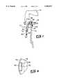
- FIG. 4is a sectional side elevational view of the outer peripheral margin portion of a lid embodying various of the features of the present invention
- FIG. 5is a side elevational view of the exterior of the lid portion depicted in FIG. 4 and taken generally along line 5--5 of FIG. 4;
- FIG. 6is a side elevational view of the interior of the lid portion depicted in FIG. 4 and taken generally along line 6--6 of FIG. 4;
- FIG. 7is a sectional side elevational view of the outer peripheral margin portion of a lid depicting various force vectors associated with the sealing and retention of the lid upon a receptacle, and further depicting a portion of a mold employed in the fabrication of the lid, in accordance with one aspect of the present invention.
- FIG. 8is a partial top view of a lid and depicting a ledge and its associated opening in accordance with one aspect of the present invention.
- a canister 10suitable for use in the capture of fluids withdrawn from a medical patient, such as from a surgical site on or within the body of the patient.
- the canisteris disposed uprightly, i.e. having its centerline 11 oriented vertically, unless stated otherwise, and all directions recited are to be referenced to this orientation of the canister.
- the canisterreferred to at times as a suction canister, includes a tapered, generally cylindrical receptacle 12 having a closed bottom end 14, and open top end 16 and wall means 18 connecting the bottom and top ends to define an open-top receptacle.
- the wall means 18 of the receptacleis folded back over upon itself, in a direction outwardly and downwardly of the receptacle, to define an annular skirt 20 whose innermost wall 22 overlies the uppermost portion 24 of the top portion 26 of the wall means 18, but which is spaced apart therefrom.
- this annular skirtwhen viewed in cross-section, defines an angle "A" with respect to the vertical, of about 20 degrees.
- the folding over of the top edge of the wall means 18further defines a planar rim 32 on the top end of the wall means.
- the lower edge 28 of the annular skirtdefines a horizontally oriented surface 30 (when the receptacle is disposed uprightly, i.e., vertically).
- the receptacleis molded from a plastic, such as a polystyrene plastic which provides substantial rigidity for the receptacle and permits the receptacle to be transparent for visual observation of the contents of the receptacle.
- a plasticsuch as a polystyrene plastic which provides substantial rigidity for the receptacle and permits the receptacle to be transparent for visual observation of the contents of the receptacle.
- plasticsmay be employed, but should be chosen to provide rigidity equivalent to that provided by a polystyrene plastic.
- a lid 40is provided for, among other things, closing the open top end 16 of the receptacle.
- the lid depicted in the several Figuresincludes a body portion 42 which in the depicted embodiment includes an annular concave body portion 44 oriented concentrically about an upstanding central port 46 that is adapted to be connected to a source of vacuum such as the usual vacuum connection found in medical treatment facilities.
- a port 50for connecting the interior of the receptacle in fluid flow communication to a wound site or the like from which fluids are to be collected
- an accessory port 52for connecting any of several accessory items such as containers of gelling compound in flow communication to the interior of the receptacle
- a tandem port 56for connecting the interior of the receptacle in tandem fluid flow communication with a further receptacle
- a post 58for use in storage of caps for one or more of the ports.
- other ports, tethered caps for closing off one or more of the ports, etc.may be included on the lid, all as well known in the art.
- the body portion 42 thereofincludes an annular perimetral skirt 60 which is integrally formed with the body portion 42 of the lid and depends therefrom to terminate in a circumferential rim 66.
- the junction 83 of the body portion of the lid and skirtwhen viewed in cross-section as in FIGS. 2 and 3, is radiussed such that the skirt includes an annular portion 87 that projects both downwardly and outwardly from the junction 83, for example at an angle "B" of about 20 degrees with respect to the vertical.
- the skirt 60includes a further integral annular portion 89 which is a continuation of the portion 87.
- this skirtis provided with a plurality of integrally molded ledges 62 disposed in spaced apart relationship to one another circumferentially about the inner wall 64 of the skirt 60, for example, about 45 degrees apart.
- each ledge 68projects substantially prependicularly from the skirt 60 to define an upper surface 72 and an outboard edge 70 thereof.
- Each ledgeincludes one or more ramps 68 which are inclined in a direction from the inner wall 64 of the skirt 60 toward the outboard edge 70 of their respective ledge, each ramp being disposed on that side of the ledge nearest the rim 66 of the skirt.
- the lid of the present inventionis molded from a plastic material such as high density polyethylene which is chosen to provide, among other things, a degree of resiliency to the skirt 60 of the lid. Accordingly, the skirt 60 of the present lid is amenable to being deformed outwardly from the body 42 of the lid by a distance that is only sufficient to permit the skirt 60 to pass the edge 70 of each ledge 60, and when released will rebound to its original position.
- a plastic materialsuch as high density polyethylene which is chosen to provide, among other things, a degree of resiliency to the skirt 60 of the lid. Accordingly, the skirt 60 of the present lid is amenable to being deformed outwardly from the body 42 of the lid by a distance that is only sufficient to permit the skirt 60 to pass the edge 70 of each ledge 60, and when released will rebound to its original position.
- each ledgehas associated therewith an opening 80 which extends through the thickness of the skirt 60.
- this openingis required to enable the molding of a ledge on the inner surface 64 of the skirt and thereafter to extract the molded lid from a mold 81.
- each opening 80includes a bottom wall 81 which defines a portion of a respective ledge 62, substantially parallel side walls 84 and 86 which extend upwardly from the opposite side ends 88 and 90 of a respective ledge, and an upper wall 92.
- the width of the opening 80 between its opposite side wallsis not less than, and preferably substantially equal to, the length dimension of the ledge 62.
- the height of the openingis a function of the slope or curvature of the junction 83 between the skirt 60 and the body portion 42 of the lid, but in any event, the upper wall includes a planar surface 94, no portion of which projects laterally outwardly of the lid by a distance greater than the inward limit of the outboard edge 70 of a respective ledge.
- This configuration of the walls of the opening 80is important for purposes of designing a mold 81 which includes a shoulder 85 suitable for forming the ledge during molding of the lid, and which will permit the formation of integral ledges projecting from the inner surface of the skirt, and subsequent removal of the molded lid from the mold. As will be seen further hereinafter, this configuration further makes possible the non-removable nature of the interlocking and sealing of the lid to the receptacle.
- the lid 40further includes an annular flange 100 which is integrally formed with, and depends from the inner surface 102, of the body portion 42 of the lid at a location spaced inwardly from the skirt 60 to define an annular trough 104 between the skirt and flange for the receipt therein of the top rim 32 of the receptacle.
- annular flange 100which is integrally formed with, and depends from the inner surface 102, of the body portion 42 of the lid at a location spaced inwardly from the skirt 60 to define an annular trough 104 between the skirt and flange for the receipt therein of the top rim 32 of the receptacle.
- annular sealing locationsprovide assurance of a complete vacuum and liquid seal between the lid and the receptacle.
- the outer edge 108 of the rim 32 of the receptacleengages the inner surface of the trough at a location disposed inwardly of the upper wall 90 of the skirt 60, thereby ensuring that there is sealing of the outer edge 108 to the inner wall of the trough, even in the areas where the ledges and their associated openings are located.
- the sealing of the rim of the receptacle in the trough of the lidis enhanced and insured by means of the plurality of ledges disposed about the circumference of the inner surface of the skirt of the lid.
- the separation distance between the body portion 42 of the lid and the location of each ledge on the inner surface of the skirt of the lidis chosen to be not greater than the distance between the planar rim 32 of the receptacle and the lower edge 28 of the skirt of the receptacle.
- the width and cross sectional geometry of the trough 104 of the lidis substantially equal to the width and cross sectional geometry of the upper end of the receptacle and its annular skirt so that the rim 32 snugly fits within the trough.
- the location of the ledge 62is chosen such that when the receptacle skirt is fully disposed within the trough, the ledge is allowed to move under and engage the lower edge 28 of the rim 32 providing a positive indication that the rim 32 has achieved sealing engagement within the trough and also providing for locking of the lid in engagement with the receptacle.
- Insertion of the rigid rim 32 of the receptacle into the trough 104 of the lidis made possible by means of the inherent resiliency of the lid skirt 60 and the presence of the ramps 62 associated with each ledge.
- pressureis exerted against the lid in a direction toward the receptacle. This pressure forces the lateral expansion of the lid skirt by an amount sufficient to permit the receptacle rim 32 to engage the ramps and move past the ledges to fully enter the trough 104.
- the ledgesare spaced apart from one another circumferentially of the lid skirt, preferably 45 degrees apart about the outer circumference of the lid in the instance of a circular lid. If removal of the lid is attempted by lifting outwardly and upwardly on the lid skirt at any given single location about the circumference of the skirt, only a limited portion of the skirt can be deformed.
- This limited deformation of the lid skirtis only sufficient to permit disengagement of not more than one ledge at a time from the receptacle rim, leaving the remainder of the ledges engaged and in position to retain the lid on the receptacle.
- disengagement of one ledgedoes not permit disengagement of adjacent ledges so that there is no peeling effect possible.
- the present interlocking of the lid with the receptaclehas been found to survive dropping of a fluid-filled canister onto a floor from a height of about four feet without destruction of the seal between the lid and the receptacle. Further, after the canister has been used to collect fluids and is ready for disposal of the fluids, the ports leading into and out of the interior of the canister are closed, usually by caps or plugs, and the canister and its contents may be transported safely to its point of disposal, preferably by incineration.
Landscapes
- Health & Medical Sciences (AREA)
- Heart & Thoracic Surgery (AREA)
- Vascular Medicine (AREA)
- Engineering & Computer Science (AREA)
- Anesthesiology (AREA)
- Biomedical Technology (AREA)
- Hematology (AREA)
- Life Sciences & Earth Sciences (AREA)
- Animal Behavior & Ethology (AREA)
- General Health & Medical Sciences (AREA)
- Public Health (AREA)
- Veterinary Medicine (AREA)
- External Artificial Organs (AREA)
Abstract
Description
Claims (5)
Priority Applications (1)
| Application Number | Priority Date | Filing Date | Title |
|---|---|---|---|
| US08/985,929US5960837A (en) | 1997-12-05 | 1997-12-05 | Suction canister having molded interlocking lid |
Applications Claiming Priority (1)
| Application Number | Priority Date | Filing Date | Title |
|---|---|---|---|
| US08/985,929US5960837A (en) | 1997-12-05 | 1997-12-05 | Suction canister having molded interlocking lid |
Publications (1)
| Publication Number | Publication Date |
|---|---|
| US5960837Atrue US5960837A (en) | 1999-10-05 |
Family
ID=25531918
Family Applications (1)
| Application Number | Title | Priority Date | Filing Date |
|---|---|---|---|
| US08/985,929Expired - LifetimeUS5960837A (en) | 1997-12-05 | 1997-12-05 | Suction canister having molded interlocking lid |
Country Status (1)
| Country | Link |
|---|---|
| US (1) | US5960837A (en) |
Cited By (59)
| Publication number | Priority date | Publication date | Assignee | Title |
|---|---|---|---|---|
| US20020190067A1 (en)* | 2001-04-20 | 2002-12-19 | Getsy Stephen B. | Overcap for container |
| US6588436B2 (en) | 2000-01-14 | 2003-07-08 | Dornoch Medical Systems, Inc. | Liquid waste disposal with canister flushing system having removable lid and method therefor |
| US6599049B2 (en)* | 2000-02-10 | 2003-07-29 | Mannesmann Vdo Ag | Indicating instrument |
| US6606994B1 (en)* | 2000-04-24 | 2003-08-19 | Bradley R. Clark | Automatic ventilator water trap evacuator |
| USD488558S1 (en) | 2003-02-27 | 2004-04-13 | Kci Licensing, Inc. | Drainage canister |
| US20040084450A1 (en)* | 2002-11-05 | 2004-05-06 | Tilia International, Inc. | Canister lid with improved evacuation and vent assembly |
| US20040122383A1 (en)* | 2002-12-11 | 2004-06-24 | Romano Jack W. | Method and apparatus for converting supplies and reducing waste |
| US6789690B2 (en) | 2002-04-19 | 2004-09-14 | Tilia International, Inc. | Hose direct canister lid |
| US20040193100A1 (en)* | 2003-03-25 | 2004-09-30 | Kimberly-Clark Worldwide, Inc. | Drain assembly with a piercing member for removing liquid from a gas directing tube |
| US20040193101A1 (en)* | 2003-03-25 | 2004-09-30 | Kimberly-Clark Worldwide, Inc. | Drain assembly for removing liquid from a gas directing tube |
| US20050061370A1 (en)* | 2003-08-16 | 2005-03-24 | Landen Higer | Vacuum packaging appliance spice rack |
| EP1535634A1 (en)* | 2003-11-28 | 2005-06-01 | FLOW-METER S.p.A. | Container for picking up organic liquids |
| US20050183780A1 (en)* | 2004-02-19 | 2005-08-25 | Michaels Thomas L. | Method and apparatus for the disposal of waste fluids |
| US20050187529A1 (en)* | 2004-02-17 | 2005-08-25 | Reasoner Stephen J. | Waste collection unit |
| US20050215961A1 (en)* | 2004-03-25 | 2005-09-29 | Romano Jack W | Method and apparatus for transforming a delivery container into a waste disposal system |
| US20050267425A1 (en)* | 2004-05-27 | 2005-12-01 | Scimed Life Systems, Inc. | Splash minimizing lid for liquid waste receptacle |
| US20060000733A1 (en)* | 2004-07-02 | 2006-01-05 | Albritton Charles W | Rigid container with vacuum channel walls |
| US20060085900A1 (en)* | 2004-10-22 | 2006-04-27 | Domestic Sanitation Corporation | Vacuum tank assembly |
| US20060183617A1 (en)* | 2005-02-15 | 2006-08-17 | Rogar Capital Corporation | Forming catch tabs on paperboard food container components for retaining containers and lids in releasable attachment |
| US7153294B1 (en) | 2004-06-16 | 2006-12-26 | H2Or, Inc. | Surgical vacuum canister |
| US20080015526A1 (en)* | 2006-05-23 | 2008-01-17 | Solomon Reiner | Suction canister |
| US20090012493A1 (en)* | 2007-07-04 | 2009-01-08 | Volker Harig | Pre-evacuatable or pre-evacuated container for medical purposes |
| US20090292263A1 (en)* | 2008-05-21 | 2009-11-26 | Tyco Healthcare Group, Lp | Wound therapy system with portable container apparatus |
| WO2010021783A1 (en)* | 2008-08-21 | 2010-02-25 | Tyco Healthcare Group Lp | Sensor wth electrical contact protection for use in fluid collection canister and negative pressure wound therapy systems including same |
| DE202009015380U1 (en) | 2009-11-13 | 2010-02-25 | Gfv Verschlusstechnik Gmbh & Co. Kg | Attachment for a container and container |
| US20110118682A1 (en)* | 2006-04-17 | 2011-05-19 | Jack Woodward Romano | Supply chain method and apparatus for sealing and unsealing a vacuum draw path |
| US20110139667A1 (en)* | 2009-12-11 | 2011-06-16 | Burgess James E | Stackable Suction Canister and Lid Assembly |
| US8021347B2 (en) | 2008-07-21 | 2011-09-20 | Tyco Healthcare Group Lp | Thin film wound dressing |
| KR200456798Y1 (en) | 2008-12-16 | 2011-11-21 | 메디플랜(주) | Medical Aspiration Device |
| US8257328B2 (en) | 2008-07-08 | 2012-09-04 | Tyco Healthcare Group Lp | Portable negative pressure wound therapy device |
| US8298200B2 (en) | 2009-06-01 | 2012-10-30 | Tyco Healthcare Group Lp | System for providing continual drainage in negative pressure wound therapy |
| USD679807S1 (en)* | 2010-04-29 | 2013-04-09 | Medline Industries, Inc. | Fluid collection container lid |
| USD694404S1 (en) | 2011-06-09 | 2013-11-26 | Medline Industries, Inc. | Fluid collection container lid |
| US8777911B2 (en) | 2008-08-08 | 2014-07-15 | Smith & Nephew, Inc. | Wound dressing of continuous fibers |
| US8920394B2 (en) | 2012-12-19 | 2014-12-30 | Dornoch Medical Systems, Inc. | Suction canister liner and system |
| US9155821B2 (en) | 2009-06-10 | 2015-10-13 | Smith & Nephew, Inc. | Fluid collection canister including canister top with filter membrane and negative pressure wound therapy systems including same |
| CN105013028A (en)* | 2015-08-03 | 2015-11-04 | 江西龙之吻医疗科技有限公司 | Closed thoracic drainage device |
| US9302034B2 (en) | 2011-04-04 | 2016-04-05 | Smith & Nephew, Inc. | Negative pressure wound therapy dressing |
| USD763691S1 (en) | 2014-11-13 | 2016-08-16 | Cornerstone Cm, Inc. | Cap for a bottle |
| USD764920S1 (en) | 2014-11-13 | 2016-08-30 | Cornerstone Cm, Inc. | Bottle |
| US9474837B2 (en) | 2013-07-03 | 2016-10-25 | Dornoch Medical Systems, Inc. | Fluid level sensor cover for a medical waste fluid collection and disposal system |
| US9505599B2 (en) | 2014-11-13 | 2016-11-29 | Cornerstone Cm, Inc. | Evacuated bottle system |
| US9517922B2 (en) | 2014-11-13 | 2016-12-13 | Cornerstone Cm, Inc. | Evacuated bottle system |
| USD846732S1 (en)* | 2017-04-04 | 2019-04-23 | Arc Medical Design Limited | Specimen trap |
| USD846733S1 (en)* | 2017-04-04 | 2019-04-23 | Arc Medical Design Limited | Specimen trap |
| USD856512S1 (en) | 2018-06-14 | 2019-08-13 | Deroyal Industries, Inc. | Canister lid |
| US10406036B2 (en) | 2009-06-18 | 2019-09-10 | Smith & Nephew, Inc. | Apparatus for vacuum bridging and/or exudate collection |
| USD859986S1 (en) | 2014-11-13 | 2019-09-17 | Cornerstone Cm, Inc. | Stopper for bottle |
| US10744239B2 (en) | 2014-07-31 | 2020-08-18 | Smith & Nephew, Inc. | Leak detection in negative pressure wound therapy system |
| US10912869B2 (en) | 2008-05-21 | 2021-02-09 | Smith & Nephew, Inc. | Wound therapy system with related methods therefor |
| US20210220851A1 (en)* | 2020-01-17 | 2021-07-22 | Port86, Llc | Dispensing Lid and Pump for a Paint Pail |
| US11141325B2 (en) | 2006-09-28 | 2021-10-12 | Smith & Nephew, Inc. | Portable wound therapy system |
| US11141520B2 (en) | 2008-02-27 | 2021-10-12 | Smith & Nephew Plc | Fluid collection |
| US11230421B2 (en) | 2014-11-13 | 2022-01-25 | Cscm Management Company Llc | Evacuated bottle system |
| US11298268B2 (en) | 2018-09-19 | 2022-04-12 | Deroyal Industries, Inc. | Multiple-wound negative pressure wound therapy using multiple fluid collection volumes |
| USD964553S1 (en) | 2020-05-29 | 2022-09-20 | Keymed (Medical & Industrial Equipment) Limited | Medical instrument |
| US11471571B2 (en) | 2017-04-19 | 2022-10-18 | Smith & Nephew, Inc. | Negative pressure wound therapy canisters |
| US12133789B2 (en) | 2014-07-31 | 2024-11-05 | Smith & Nephew, Inc. | Reduced pressure therapy apparatus construction and control |
| US12280203B2 (en) | 2019-10-03 | 2025-04-22 | T.J.Smith And Nephew, Limited | Apparatuses and methods for negative pressure wound therapy |
Citations (8)
| Publication number | Priority date | Publication date | Assignee | Title |
|---|---|---|---|---|
| US2977019A (en)* | 1957-09-19 | 1961-03-28 | Continental Can Co | Easy opening can and cover assembly |
| US3782414A (en)* | 1970-10-29 | 1974-01-01 | Medical Dev Corp | Body fluid collection bottle |
| US3965902A (en)* | 1973-03-23 | 1976-06-29 | Respiratory Care, Inc. | Disposable fluid collection container |
| US4430084A (en)* | 1980-01-21 | 1984-02-07 | American Hospital Supply Corp. | Method for pre-use storage of a medical receptacle |
| US5185007A (en)* | 1989-03-30 | 1993-02-09 | Abbott Laboratories | Suction drainage infection control system |
| US5254080A (en)* | 1990-03-14 | 1993-10-19 | Minnesota Mining And Manufacturing Company | Quick-changeover apparatus for handling medical fluid |
| US5381918A (en)* | 1989-10-18 | 1995-01-17 | Herberts Gesellschaft Mit Beschrankter Haftung | Device for securing the lid of a can, in particular, a can of paint |
| US5538154A (en)* | 1993-06-14 | 1996-07-23 | Von Holdt; John W. | Snap-on, flexible lid |
- 1997
- 1997-12-05USUS08/985,929patent/US5960837A/ennot_activeExpired - Lifetime
Patent Citations (8)
| Publication number | Priority date | Publication date | Assignee | Title |
|---|---|---|---|---|
| US2977019A (en)* | 1957-09-19 | 1961-03-28 | Continental Can Co | Easy opening can and cover assembly |
| US3782414A (en)* | 1970-10-29 | 1974-01-01 | Medical Dev Corp | Body fluid collection bottle |
| US3965902A (en)* | 1973-03-23 | 1976-06-29 | Respiratory Care, Inc. | Disposable fluid collection container |
| US4430084A (en)* | 1980-01-21 | 1984-02-07 | American Hospital Supply Corp. | Method for pre-use storage of a medical receptacle |
| US5185007A (en)* | 1989-03-30 | 1993-02-09 | Abbott Laboratories | Suction drainage infection control system |
| US5381918A (en)* | 1989-10-18 | 1995-01-17 | Herberts Gesellschaft Mit Beschrankter Haftung | Device for securing the lid of a can, in particular, a can of paint |
| US5254080A (en)* | 1990-03-14 | 1993-10-19 | Minnesota Mining And Manufacturing Company | Quick-changeover apparatus for handling medical fluid |
| US5538154A (en)* | 1993-06-14 | 1996-07-23 | Von Holdt; John W. | Snap-on, flexible lid |
Non-Patent Citations (8)
| Title |
|---|
| Product Brochure: Bemis 800 cc System III, 1994, Bemis Healthcare, Sheboygan Fall, WI 53085, 2 pages.* |
| Product Brochure: Bemis System II, 1994, Bemis Healthcare, Sheboygan Falls, WI 53085, 2 pages.* |
| Product Brochure: Bemis System III, 1994, Bemis Healthcare, Sheboygan Falls, WI 53085, 2 pages.* |
| Product Brochure: Medi Vac CRD Suction System, 1995, Baxter Healthcare Corporation, McGaw Park, IL 60085, 2 pages.* |
| Product Brochure: Medi-Vac CRD Suction System, 1995, Baxter Healthcare Corporation, McGaw Park, IL 60085, 2 pages. |
| Product Brochure: New from EZE VAC, 1991, Abbott Laboratories, Hospital Products Division, North Chicago, IL 60064, 4 pages.* |
| Product Brochure: New from EZE-VAC, 1991, Abbott Laboratories, Hospital Products Division, North Chicago, IL 60064, 4 pages. |
| Product Brochure: Receptal, 1987, Abbott Laboratories, Hospital Products Division, North Chicago, IL 60064: 4 pages.* |
Cited By (117)
| Publication number | Priority date | Publication date | Assignee | Title |
|---|---|---|---|---|
| US6796317B2 (en)* | 2000-01-14 | 2004-09-28 | Dornoch Medical Systems, Inc. | Liquid waste disposal canister |
| US6588436B2 (en) | 2000-01-14 | 2003-07-08 | Dornoch Medical Systems, Inc. | Liquid waste disposal with canister flushing system having removable lid and method therefor |
| US20030164180A1 (en)* | 2000-01-14 | 2003-09-04 | Dunn James L. | Liquid waste disposal and canister flushing system and method |
| US6599049B2 (en)* | 2000-02-10 | 2003-07-29 | Mannesmann Vdo Ag | Indicating instrument |
| US6606994B1 (en)* | 2000-04-24 | 2003-08-19 | Bradley R. Clark | Automatic ventilator water trap evacuator |
| US20020190067A1 (en)* | 2001-04-20 | 2002-12-19 | Getsy Stephen B. | Overcap for container |
| US6789690B2 (en) | 2002-04-19 | 2004-09-14 | Tilia International, Inc. | Hose direct canister lid |
| US7048136B2 (en) | 2002-11-05 | 2006-05-23 | Tilia International, Inc. | Canister lid with improved evacuation and vent assembly |
| US20040084450A1 (en)* | 2002-11-05 | 2004-05-06 | Tilia International, Inc. | Canister lid with improved evacuation and vent assembly |
| US20040122383A1 (en)* | 2002-12-11 | 2004-06-24 | Romano Jack W. | Method and apparatus for converting supplies and reducing waste |
| US7329250B2 (en) | 2002-12-11 | 2008-02-12 | Medindica - Pak, Inc. | Method and apparatus for converting supplies and reducing waste |
| USD488558S1 (en) | 2003-02-27 | 2004-04-13 | Kci Licensing, Inc. | Drainage canister |
| US20040193100A1 (en)* | 2003-03-25 | 2004-09-30 | Kimberly-Clark Worldwide, Inc. | Drain assembly with a piercing member for removing liquid from a gas directing tube |
| US20040193101A1 (en)* | 2003-03-25 | 2004-09-30 | Kimberly-Clark Worldwide, Inc. | Drain assembly for removing liquid from a gas directing tube |
| US20050061370A1 (en)* | 2003-08-16 | 2005-03-24 | Landen Higer | Vacuum packaging appliance spice rack |
| EP1535634A1 (en)* | 2003-11-28 | 2005-06-01 | FLOW-METER S.p.A. | Container for picking up organic liquids |
| US20050187529A1 (en)* | 2004-02-17 | 2005-08-25 | Reasoner Stephen J. | Waste collection unit |
| US7481243B2 (en) | 2004-02-19 | 2009-01-27 | Allegiance Corporation | Method and apparatus for the disposal of waste fluids |
| US8651531B2 (en) | 2004-02-19 | 2014-02-18 | Allegiance Corporation | Method and apparatus for the disposal of waste fluids |
| US20050183780A1 (en)* | 2004-02-19 | 2005-08-25 | Michaels Thomas L. | Method and apparatus for the disposal of waste fluids |
| US20090151793A1 (en)* | 2004-02-19 | 2009-06-18 | Allegiance Corporation | Method and Apparatus for the Disposal of Waste Fluids |
| US8137329B2 (en)* | 2004-03-25 | 2012-03-20 | Medindica-Pak, Inc. | Method and apparatus for transforming a delivery container into a waste disposal system |
| US20050215961A1 (en)* | 2004-03-25 | 2005-09-29 | Romano Jack W | Method and apparatus for transforming a delivery container into a waste disposal system |
| US20050267425A1 (en)* | 2004-05-27 | 2005-12-01 | Scimed Life Systems, Inc. | Splash minimizing lid for liquid waste receptacle |
| US7644834B2 (en) | 2004-05-27 | 2010-01-12 | Navilyst Medical, Inc. | Splash minimizing lid for liquid waste receptacle |
| US7153294B1 (en) | 2004-06-16 | 2006-12-26 | H2Or, Inc. | Surgical vacuum canister |
| US20060000733A1 (en)* | 2004-07-02 | 2006-01-05 | Albritton Charles W | Rigid container with vacuum channel walls |
| US7373946B2 (en)* | 2004-10-22 | 2008-05-20 | Dometic Sanitation Corporation | Vacuum tank assembly |
| US20060085900A1 (en)* | 2004-10-22 | 2006-04-27 | Domestic Sanitation Corporation | Vacuum tank assembly |
| US20060183617A1 (en)* | 2005-02-15 | 2006-08-17 | Rogar Capital Corporation | Forming catch tabs on paperboard food container components for retaining containers and lids in releasable attachment |
| US8905984B2 (en)* | 2006-04-17 | 2014-12-09 | Medindica-Pak, Inc. | Supply chain method and apparatus for sealing and unsealing a vacuum draw path |
| US20110118682A1 (en)* | 2006-04-17 | 2011-05-19 | Jack Woodward Romano | Supply chain method and apparatus for sealing and unsealing a vacuum draw path |
| US20080015526A1 (en)* | 2006-05-23 | 2008-01-17 | Solomon Reiner | Suction canister |
| US11141325B2 (en) | 2006-09-28 | 2021-10-12 | Smith & Nephew, Inc. | Portable wound therapy system |
| US12115302B2 (en) | 2006-09-28 | 2024-10-15 | Smith & Nephew, Inc. | Portable wound therapy system |
| US9011407B2 (en)* | 2007-07-04 | 2015-04-21 | Pfm Medical Ag | Pre-evacuatable or pre-evacuated container for medical purposes |
| US20090012493A1 (en)* | 2007-07-04 | 2009-01-08 | Volker Harig | Pre-evacuatable or pre-evacuated container for medical purposes |
| US11141520B2 (en) | 2008-02-27 | 2021-10-12 | Smith & Nephew Plc | Fluid collection |
| US12201764B2 (en) | 2008-02-27 | 2025-01-21 | Smith & Nephew Plc | Fluid collection |
| US8834452B2 (en) | 2008-05-21 | 2014-09-16 | Smith & Nephew, Inc. | Wound therapy system and related methods therefor |
| US9974890B2 (en) | 2008-05-21 | 2018-05-22 | Smith & Nephew, Inc. | Wound therapy system and related methods therefor |
| US8414519B2 (en) | 2008-05-21 | 2013-04-09 | Covidien Lp | Wound therapy system with portable container apparatus |
| US10912869B2 (en) | 2008-05-21 | 2021-02-09 | Smith & Nephew, Inc. | Wound therapy system with related methods therefor |
| US10967106B2 (en) | 2008-05-21 | 2021-04-06 | Smith & Nephew, Inc. | Wound therapy system and related methods therefor |
| US20090292263A1 (en)* | 2008-05-21 | 2009-11-26 | Tyco Healthcare Group, Lp | Wound therapy system with portable container apparatus |
| US9375521B2 (en) | 2008-05-21 | 2016-06-28 | Smith & Nephew, Inc. | Wound therapy system and related methods therefor |
| US8257328B2 (en) | 2008-07-08 | 2012-09-04 | Tyco Healthcare Group Lp | Portable negative pressure wound therapy device |
| US9017302B2 (en) | 2008-07-21 | 2015-04-28 | Smith & Nephew, Inc. | Thin film wound dressing |
| US8021347B2 (en) | 2008-07-21 | 2011-09-20 | Tyco Healthcare Group Lp | Thin film wound dressing |
| US10016545B2 (en) | 2008-07-21 | 2018-07-10 | Smith & Nephew, Inc. | Thin film wound dressing |
| US9474654B2 (en) | 2008-08-08 | 2016-10-25 | Smith & Nephew, Inc. | Wound dressing of continuous fibers |
| US8777911B2 (en) | 2008-08-08 | 2014-07-15 | Smith & Nephew, Inc. | Wound dressing of continuous fibers |
| US8827983B2 (en) | 2008-08-21 | 2014-09-09 | Smith & Nephew, Inc. | Sensor with electrical contact protection for use in fluid collection canister and negative pressure wound therapy systems including same |
| US9801984B2 (en) | 2008-08-21 | 2017-10-31 | Smith & Nephew, Inc. | Sensor with electrical contact protection for use in fluid collection canister and negative pressure wound therapy systems including same |
| US10737000B2 (en) | 2008-08-21 | 2020-08-11 | Smith & Nephew, Inc. | Sensor with electrical contact protection for use in fluid collection canister and negative pressure wound therapy systems including same |
| US20100049150A1 (en)* | 2008-08-21 | 2010-02-25 | Tyco Healthcare Group Lp | Sensor with Electrical Contact Protection for Use in Fluid Collection Canister and Negative Pressure Wound Therapy Systems Including Same |
| WO2010021783A1 (en)* | 2008-08-21 | 2010-02-25 | Tyco Healthcare Group Lp | Sensor wth electrical contact protection for use in fluid collection canister and negative pressure wound therapy systems including same |
| US9415145B2 (en) | 2008-08-21 | 2016-08-16 | Smith & Nephew, Inc. | Sensor with electrical contact protection for use in fluid collection canister and negative pressure wound therapy systems including same |
| KR200456798Y1 (en) | 2008-12-16 | 2011-11-21 | 메디플랜(주) | Medical Aspiration Device |
| US8298200B2 (en) | 2009-06-01 | 2012-10-30 | Tyco Healthcare Group Lp | System for providing continual drainage in negative pressure wound therapy |
| US8784392B2 (en) | 2009-06-01 | 2014-07-22 | Smith & Nephew, Inc. | System for providing continual drainage in negative pressure wound therapy |
| US11992601B2 (en) | 2009-06-01 | 2024-05-28 | Smith & Nephew, Inc. | System for providing continual drainage in negative pressure wound therapy |
| US10828404B2 (en) | 2009-06-01 | 2020-11-10 | Smith & Nephew, Inc. | System for providing continual drainage in negative pressure wound therapy |
| US9889241B2 (en) | 2009-06-01 | 2018-02-13 | Smith & Nephew, Inc. | System for providing continual drainage in negative pressure wound therapy |
| US9155821B2 (en) | 2009-06-10 | 2015-10-13 | Smith & Nephew, Inc. | Fluid collection canister including canister top with filter membrane and negative pressure wound therapy systems including same |
| US10406036B2 (en) | 2009-06-18 | 2019-09-10 | Smith & Nephew, Inc. | Apparatus for vacuum bridging and/or exudate collection |
| DE202009015380U1 (en) | 2009-11-13 | 2010-02-25 | Gfv Verschlusstechnik Gmbh & Co. Kg | Attachment for a container and container |
| EP2322447A1 (en) | 2009-11-13 | 2011-05-18 | GFV Verschlusstechnik GmbH & Co. KG | Attachment for a container and container |
| US20110139667A1 (en)* | 2009-12-11 | 2011-06-16 | Burgess James E | Stackable Suction Canister and Lid Assembly |
| USD679807S1 (en)* | 2010-04-29 | 2013-04-09 | Medline Industries, Inc. | Fluid collection container lid |
| US9302034B2 (en) | 2011-04-04 | 2016-04-05 | Smith & Nephew, Inc. | Negative pressure wound therapy dressing |
| US10154929B2 (en) | 2011-04-04 | 2018-12-18 | Smith & Nephew, Inc. | Negative pressure wound therapy dressing |
| USD789522S1 (en) | 2011-06-09 | 2017-06-13 | Medline Industries, Inc. | Fluid collection container lid |
| USD694404S1 (en) | 2011-06-09 | 2013-11-26 | Medline Industries, Inc. | Fluid collection container lid |
| USD705926S1 (en)* | 2011-06-09 | 2014-05-27 | Medline Industries, Inc | Fluid collection container lid |
| US8920394B2 (en) | 2012-12-19 | 2014-12-30 | Dornoch Medical Systems, Inc. | Suction canister liner and system |
| US9474837B2 (en) | 2013-07-03 | 2016-10-25 | Dornoch Medical Systems, Inc. | Fluid level sensor cover for a medical waste fluid collection and disposal system |
| US10583227B2 (en) | 2013-07-03 | 2020-03-10 | Dornoch Medical Systems, Inc. | Fluid level sensor cover for a medical waste fluid collection and disposal system |
| US12133789B2 (en) | 2014-07-31 | 2024-11-05 | Smith & Nephew, Inc. | Reduced pressure therapy apparatus construction and control |
| US12115298B2 (en) | 2014-07-31 | 2024-10-15 | Smith & Nephew, Inc. | Wound pressure determination for reduced pressure wound therapy |
| US10744239B2 (en) | 2014-07-31 | 2020-08-18 | Smith & Nephew, Inc. | Leak detection in negative pressure wound therapy system |
| US10961039B2 (en) | 2014-11-13 | 2021-03-30 | Cornerstone Cm, Inc | Evacuated bottle system |
| USD764920S1 (en) | 2014-11-13 | 2016-08-30 | Cornerstone Cm, Inc. | Bottle |
| USD871220S1 (en) | 2014-11-13 | 2019-12-31 | Cornerstone Cm, Inc. | Bottle |
| USD805899S1 (en) | 2014-11-13 | 2017-12-26 | Cornerstone Cm, Inc. | Stopper for bottle |
| US9517922B2 (en) | 2014-11-13 | 2016-12-13 | Cornerstone Cm, Inc. | Evacuated bottle system |
| US10308415B2 (en) | 2014-11-13 | 2019-06-04 | Cornerstone Cm, Inc. | Evacuated bottle system |
| US9505599B2 (en) | 2014-11-13 | 2016-11-29 | Cornerstone Cm, Inc. | Evacuated bottle system |
| US10836556B2 (en) | 2014-11-13 | 2020-11-17 | Cornerstone Cm, Inc. | Evacuated bottle system |
| US10858168B2 (en) | 2014-11-13 | 2020-12-08 | Cornerstone Cm, Inc. | Evacuated bottle system |
| US10017315B2 (en) | 2014-11-13 | 2018-07-10 | Cornerstone C.M, Inc. | Evacuated bottle system |
| USD908486S1 (en) | 2014-11-13 | 2021-01-26 | Cornerstone Cm, Inc. | Stopper for bottle |
| US11560267B2 (en) | 2014-11-13 | 2023-01-24 | Cscm Management Company Llc | Evacuated bottle system |
| USD809923S1 (en) | 2014-11-13 | 2018-02-13 | Cornerstone Cm, Inc. | Bottle |
| USD976705S1 (en) | 2014-11-13 | 2023-01-31 | Cscm Management Company Llc | Cap for a bottle |
| USD920796S1 (en) | 2014-11-13 | 2021-06-01 | Cornerstone Cm, Inc. | Bottle |
| US10106308B2 (en) | 2014-11-13 | 2018-10-23 | Cornerstone C.M., Inc. | Evacuated bottle system |
| USD926572S1 (en) | 2014-11-13 | 2021-08-03 | Cornerstone Cm, Inc. | Stopper for bottle |
| USD763691S1 (en) | 2014-11-13 | 2016-08-16 | Cornerstone Cm, Inc. | Cap for a bottle |
| USD859986S1 (en) | 2014-11-13 | 2019-09-17 | Cornerstone Cm, Inc. | Stopper for bottle |
| US11230421B2 (en) | 2014-11-13 | 2022-01-25 | Cscm Management Company Llc | Evacuated bottle system |
| US11242185B2 (en) | 2014-11-13 | 2022-02-08 | Cscm Management Company Llc | Evacuated bottle system |
| US11254484B2 (en) | 2014-11-13 | 2022-02-22 | Cscm Management Company Llc | Evacuated bottle system |
| USD946400S1 (en) | 2014-11-13 | 2022-03-22 | Cscm Management Company Llc | Funnel |
| US10252851B2 (en) | 2014-11-13 | 2019-04-09 | Cornerstone Cm, Inc. | Evacuated bottle system |
| CN105013028A (en)* | 2015-08-03 | 2015-11-04 | 江西龙之吻医疗科技有限公司 | Closed thoracic drainage device |
| USD846732S1 (en)* | 2017-04-04 | 2019-04-23 | Arc Medical Design Limited | Specimen trap |
| USD846733S1 (en)* | 2017-04-04 | 2019-04-23 | Arc Medical Design Limited | Specimen trap |
| US11471571B2 (en) | 2017-04-19 | 2022-10-18 | Smith & Nephew, Inc. | Negative pressure wound therapy canisters |
| US11572221B1 (en) | 2018-06-14 | 2023-02-07 | Deroyal Industries, Inc | Canister lid |
| US10865017B1 (en) | 2018-06-14 | 2020-12-15 | Deroyal Industries, Inc. | Mold for making canister lid |
| USD856512S1 (en) | 2018-06-14 | 2019-08-13 | Deroyal Industries, Inc. | Canister lid |
| US11786411B2 (en) | 2018-09-19 | 2023-10-17 | Deroyal Industries, Inc. | Multiple-wound negative pressure wound therapy using multiple fluid collection volumes |
| US11298268B2 (en) | 2018-09-19 | 2022-04-12 | Deroyal Industries, Inc. | Multiple-wound negative pressure wound therapy using multiple fluid collection volumes |
| US12280203B2 (en) | 2019-10-03 | 2025-04-22 | T.J.Smith And Nephew, Limited | Apparatuses and methods for negative pressure wound therapy |
| US20210220851A1 (en)* | 2020-01-17 | 2021-07-22 | Port86, Llc | Dispensing Lid and Pump for a Paint Pail |
| USD964553S1 (en) | 2020-05-29 | 2022-09-20 | Keymed (Medical & Industrial Equipment) Limited | Medical instrument |
Similar Documents
| Publication | Publication Date | Title |
|---|---|---|
| US5960837A (en) | Suction canister having molded interlocking lid | |
| EP0651718B1 (en) | Multiple cap seal for containers | |
| JP3721519B2 (en) | Device for collecting fluid from a patient | |
| CA2221787C (en) | Locking cap for the pour spout of a suction container | |
| US4878595A (en) | Tamper resistant wide mouth package with labyrinth seal | |
| US8322565B2 (en) | Container and cap assembly | |
| US5692651A (en) | Self-sealing dispensing closure | |
| JP3707561B2 (en) | Waste drug reservoir for suction-type drainage system | |
| US5529202A (en) | Closure for containers and the like | |
| JP4913166B2 (en) | Cap and cap assembly for centrifuge container | |
| CA1299549C (en) | Disposable container | |
| NL1009470C1 (en) | Delivery closure with pressure-operated valve. | |
| US6910607B2 (en) | Cover for dispensing closure with pressure actuated valve | |
| CN103987626B (en) | eyewash container | |
| GB1580305A (en) | Airtight container | |
| US7740155B1 (en) | Self closing cap for dispensing fluids | |
| US20080073368A1 (en) | Containers with discontinuous seal | |
| KR100690036B1 (en) | Medical Infectious Waste Containers | |
| EP0267776A2 (en) | Vessel for disposal of surgical waste | |
| US6659296B2 (en) | Cap for container | |
| US8920394B2 (en) | Suction canister liner and system | |
| US3760967A (en) | Infant feeding unit assembly | |
| RU21288U1 (en) | COSMETIC COVER | |
| PT8968U (en) | TOXIC WASTE CONTAINER | |
| EP1122185A2 (en) | Cap for container |
Legal Events
| Date | Code | Title | Description |
|---|---|---|---|
| AS | Assignment | Owner name:DEROYAL INDUSTRIES, INC., TENNESSEE Free format text:ASSIGNMENT OF ASSIGNORS INTEREST;ASSIGNOR:CUDE, J. MICHAEL;REEL/FRAME:008898/0623 Effective date:19971202 | |
| STCF | Information on status: patent grant | Free format text:PATENTED CASE | |
| AS | Assignment | Owner name:AMSOUTH BANK, TENNESSEE Free format text:SECURITY INTEREST;ASSIGNOR:DEROYAL INDUSTRIES, INC.;REEL/FRAME:012822/0959 Effective date:20020415 | |
| FPAY | Fee payment | Year of fee payment:4 | |
| FPAY | Fee payment | Year of fee payment:8 | |
| AS | Assignment | Owner name:REGIONS BANK, TENNESSEE Free format text:AMENDED AND RESTATED SECURITY AGREEMENT;ASSIGNOR:DEROYAL INDUSTRIES, INC.;REEL/FRAME:020325/0001 Effective date:20071227 | |
| REMI | Maintenance fee reminder mailed | ||
| FPAY | Fee payment | Year of fee payment:12 | |
| SULP | Surcharge for late payment | Year of fee payment:11 | |
| AS | Assignment | Owner name:REGIONS BANK, TENNESSEE Free format text:SECURITY INTEREST;ASSIGNOR:DEROYAL INDUSTRIES, INC.;REEL/FRAME:033624/0862 Effective date:20140421 | |
| AS | Assignment | Owner name:REGIONS BANK, TENNESSEE Free format text:SECURITY INTEREST;ASSIGNOR:DEROYAL INDUSTRIES, INC.;REEL/FRAME:062079/0779 Effective date:20191229 |