US5960766A - Method of operating an internal combustion engine - Google Patents
Method of operating an internal combustion engineDownload PDFInfo
- Publication number
- US5960766A US5960766AUS08/819,947US81994797AUS5960766AUS 5960766 AUS5960766 AUS 5960766AUS 81994797 AUS81994797 AUS 81994797AUS 5960766 AUS5960766 AUS 5960766A
- Authority
- US
- United States
- Prior art keywords
- fuel
- bowl
- internal combustion
- combustion engine
- set forth
- Prior art date
- Legal status (The legal status is an assumption and is not a legal conclusion. Google has not performed a legal analysis and makes no representation as to the accuracy of the status listed.)
- Expired - Fee Related
Links
- 238000002485combustion reactionMethods0.000titleclaimsabstractdescription110
- 238000000034methodMethods0.000titleclaimsabstractdescription22
- 239000000446fuelSubstances0.000claimsabstractdescription150
- 239000000203mixtureSubstances0.000claimsabstractdescription20
- 239000007789gasSubstances0.000claimsabstractdescription7
- 238000002347injectionMethods0.000claimsdescription25
- 239000007924injectionSubstances0.000claimsdescription25
- 230000009977dual effectEffects0.000claimsdescription10
- 238000004146energy storageMethods0.000claimsdescription7
- 230000001174ascending effectEffects0.000claimsdescription3
- 230000007704transitionEffects0.000claimsdescription3
- 238000013517stratificationMethods0.000abstractdescription14
- 238000011144upstream manufacturingMethods0.000description5
- 206010061218InflammationDiseases0.000description3
- 238000009826distributionMethods0.000description3
- 230000004054inflammatory processEffects0.000description3
- 230000000284resting effectEffects0.000description3
- 230000002349favourable effectEffects0.000description2
- 239000002828fuel tankSubstances0.000description2
- 239000011324beadSubstances0.000description1
- 230000015572biosynthetic processEffects0.000description1
- 230000009194climbingEffects0.000description1
- 230000006835compressionEffects0.000description1
- 238000007906compressionMethods0.000description1
- 230000003750conditioning effectEffects0.000description1
- 230000003292diminished effectEffects0.000description1
- 230000000694effectsEffects0.000description1
- 239000007788liquidSubstances0.000description1
- 230000002093peripheral effectEffects0.000description1
- 238000002360preparation methodMethods0.000description1
- 230000000644propagated effectEffects0.000description1
- 238000003892spreadingMethods0.000description1
- XLYOFNOQVPJJNP-UHFFFAOYSA-NwaterSubstancesOXLYOFNOQVPJJNP-UHFFFAOYSA-N0.000description1
Images


Classifications
- F—MECHANICAL ENGINEERING; LIGHTING; HEATING; WEAPONS; BLASTING
- F02—COMBUSTION ENGINES; HOT-GAS OR COMBUSTION-PRODUCT ENGINE PLANTS
- F02B—INTERNAL-COMBUSTION PISTON ENGINES; COMBUSTION ENGINES IN GENERAL
- F02B17/00—Engines characterised by means for effecting stratification of charge in cylinders
- F02B17/005—Engines characterised by means for effecting stratification of charge in cylinders having direct injection in the combustion chamber
- F—MECHANICAL ENGINEERING; LIGHTING; HEATING; WEAPONS; BLASTING
- F02—COMBUSTION ENGINES; HOT-GAS OR COMBUSTION-PRODUCT ENGINE PLANTS
- F02B—INTERNAL-COMBUSTION PISTON ENGINES; COMBUSTION ENGINES IN GENERAL
- F02B23/00—Other engines characterised by special shape or construction of combustion chambers to improve operation
- F02B23/08—Other engines characterised by special shape or construction of combustion chambers to improve operation with positive ignition
- F02B23/10—Other engines characterised by special shape or construction of combustion chambers to improve operation with positive ignition with separate admission of air and fuel into cylinder
- F02B23/101—Other engines characterised by special shape or construction of combustion chambers to improve operation with positive ignition with separate admission of air and fuel into cylinder the injector being placed on or close to the cylinder centre axis, e.g. with mixture formation using spray guided concepts
- F—MECHANICAL ENGINEERING; LIGHTING; HEATING; WEAPONS; BLASTING
- F02—COMBUSTION ENGINES; HOT-GAS OR COMBUSTION-PRODUCT ENGINE PLANTS
- F02F—CYLINDERS, PISTONS OR CASINGS, FOR COMBUSTION ENGINES; ARRANGEMENTS OF SEALINGS IN COMBUSTION ENGINES
- F02F3/00—Pistons
- F02F3/26—Pistons having combustion chamber in piston head
- F—MECHANICAL ENGINEERING; LIGHTING; HEATING; WEAPONS; BLASTING
- F02—COMBUSTION ENGINES; HOT-GAS OR COMBUSTION-PRODUCT ENGINE PLANTS
- F02M—SUPPLYING COMBUSTION ENGINES IN GENERAL WITH COMBUSTIBLE MIXTURES OR CONSTITUENTS THEREOF
- F02M51/00—Fuel-injection apparatus characterised by being operated electrically
- F02M51/04—Pumps peculiar thereto
- F—MECHANICAL ENGINEERING; LIGHTING; HEATING; WEAPONS; BLASTING
- F02—COMBUSTION ENGINES; HOT-GAS OR COMBUSTION-PRODUCT ENGINE PLANTS
- F02B—INTERNAL-COMBUSTION PISTON ENGINES; COMBUSTION ENGINES IN GENERAL
- F02B23/00—Other engines characterised by special shape or construction of combustion chambers to improve operation
- F02B23/08—Other engines characterised by special shape or construction of combustion chambers to improve operation with positive ignition
- F02B23/10—Other engines characterised by special shape or construction of combustion chambers to improve operation with positive ignition with separate admission of air and fuel into cylinder
- F02B2023/102—Other engines characterised by special shape or construction of combustion chambers to improve operation with positive ignition with separate admission of air and fuel into cylinder the spark plug being placed offset the cylinder centre axis
- F—MECHANICAL ENGINEERING; LIGHTING; HEATING; WEAPONS; BLASTING
- F02—COMBUSTION ENGINES; HOT-GAS OR COMBUSTION-PRODUCT ENGINE PLANTS
- F02B—INTERNAL-COMBUSTION PISTON ENGINES; COMBUSTION ENGINES IN GENERAL
- F02B23/00—Other engines characterised by special shape or construction of combustion chambers to improve operation
- F02B23/08—Other engines characterised by special shape or construction of combustion chambers to improve operation with positive ignition
- F02B23/10—Other engines characterised by special shape or construction of combustion chambers to improve operation with positive ignition with separate admission of air and fuel into cylinder
- F02B2023/108—Swirl flow, i.e. the axis of rotation of the main charge flow motion is vertical
- F—MECHANICAL ENGINEERING; LIGHTING; HEATING; WEAPONS; BLASTING
- F02—COMBUSTION ENGINES; HOT-GAS OR COMBUSTION-PRODUCT ENGINE PLANTS
- F02B—INTERNAL-COMBUSTION PISTON ENGINES; COMBUSTION ENGINES IN GENERAL
- F02B75/00—Other engines
- F02B75/02—Engines characterised by their cycles, e.g. six-stroke
- F02B2075/022—Engines characterised by their cycles, e.g. six-stroke having less than six strokes per cycle
- F02B2075/025—Engines characterised by their cycles, e.g. six-stroke having less than six strokes per cycle two
- F—MECHANICAL ENGINEERING; LIGHTING; HEATING; WEAPONS; BLASTING
- F02—COMBUSTION ENGINES; HOT-GAS OR COMBUSTION-PRODUCT ENGINE PLANTS
- F02B—INTERNAL-COMBUSTION PISTON ENGINES; COMBUSTION ENGINES IN GENERAL
- F02B75/00—Other engines
- F02B75/12—Other methods of operation
- F02B2075/125—Direct injection in the combustion chamber for spark ignition engines, i.e. not in pre-combustion chamber
- Y—GENERAL TAGGING OF NEW TECHNOLOGICAL DEVELOPMENTS; GENERAL TAGGING OF CROSS-SECTIONAL TECHNOLOGIES SPANNING OVER SEVERAL SECTIONS OF THE IPC; TECHNICAL SUBJECTS COVERED BY FORMER USPC CROSS-REFERENCE ART COLLECTIONS [XRACs] AND DIGESTS
- Y02—TECHNOLOGIES OR APPLICATIONS FOR MITIGATION OR ADAPTATION AGAINST CLIMATE CHANGE
- Y02T—CLIMATE CHANGE MITIGATION TECHNOLOGIES RELATED TO TRANSPORTATION
- Y02T10/00—Road transport of goods or passengers
- Y02T10/10—Internal combustion engine [ICE] based vehicles
- Y02T10/12—Improving ICE efficiencies
Definitions
- the inventionrelates to a method of operating an internal combustion engine and to an internal combustion engine.
- this internal combustion enginecomprises a combustion chamber defined by a head.
- a combustion chamberdefined by a head.
- In the cylinder headat least one intake valve and one exhaust valve is arranged.
- an injector nozzlePorting into the combustion chamber at the edge portion of the cylinder head directly juxtaposed to the injection valve is an injector nozzle capable of injecting fuel into the combustion chamber at a shallow angle.
- the cylinder headIn its middle portion the cylinder head is elongated downwards into the combustion chamber.
- a spark plugis vertically secured, it protruding into the combustion chamber by its ignition electrodes.
- the pistonAt top dead center (TDC) the piston is at its maximum top position and is directly arranged on the cylinder head by its piston crown.
- the piston crownIn the region of the spark plug the piston crown comprises a small dish-shaped recess surrounding the ignition electrodes of the spark plug at top dead center of the piston.
- a dish-shaped depressionis incorporated in the piston crown. This depression extends from the injector nozzle to the recess in the piston crown, into which the ignition electrodes protrude.
- a first amount of fuelis injected shortly after the piston has reached bottom dead center BDC.
- the first amount of fuelis mixed with the inducted air to form a lean fuel/air mixture.
- a second amount of fuelis injected when the piston is located roughly halfway between upper and lower dead center, so that the fuel vertically impinges the depression and only a minor portion thereof collects in the recess.
- the fuel/air mixture injected initiallyis enriched in the region of the recess to become an ignitable mixture capable of being ignited by the spark plug.
- This internal combustion enginethus operates at high load in accordance with the so-called principle of charge stratification once differingly rich fuel/air mixtures have formed in differing regions in the combustion chamber, the region about the intake duct being richer and thus more ignitable than the remaining regions.
- Charge stratification by dual injectionthus serves above all to operate lean engines.
- German Patent 41 10 618an internal combustion engine is known having a fuel-injection control system which generates a charge stratification by two-stage fuel injection in a medium load range.
- a first amount of fuelis injected in advance and mixes with the inducted air to form a lean fuel/air mixture.
- a second amount of fuelis injected into the region of the spark plug shortly before the ignition point and ignited. The second amount of fuel serves to assist igniting the lean fuel/air mixture.
- this internal combustion engineis operated with an homogenous charge stratification.
- the inventionis based on the object of achieving a simple method of operating an internal combustion engine by means of charge stratification which is more particularly suitable for two-stroke internal combustion engines.
- the inventionis further based on the object of defining an internal combustion engine in which charge stratification can be effectively introduced by simple ways and means and which features very good running properties for both minimum and medium engine loads.
- a jet of fuelis injected by an injector nozzle into a combustion chamber oriented at a steep angle relative to a piston crown, whereby in the region of the piston crown on which the jet of fuel impinges a bowl is configured so that the fuel is reflected back into the combustion chamber.
- This reflection of the fuelcreates in the combustion chamber a region having a predetermined fuel/air ratio.
- the fuel/air ratio in this regiondiffers from that of the remaining region of the combustion chamber by the fuel being introduced directly by the jet of fuel, as a result of which a specific inhomogenous charge distribution is achieved with but a single jet of fuel and thus a desired charge stratification, i.e. no complicated dual injection being necessary.
- FIG. 1is a vertical section through a combustion chamber of an internal combustion engine
- FIG. 2is a vertical section through a combustion chamber of a second example embodiment of an internal combustion engine
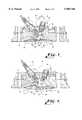
- FIG. 3is a vertical section through a combustion chamber of a third example embodiment of an internal combustion engine
- FIG. 4is a plan view of a piston used in the example embodiment shown in FIG. 3,
- FIG. 5is a longitudinal section of an injection pump.
- the method in accordance with the inventionis applied to an internal combustion engine 1 comprising by known ways and means a cylinder 2 in which a piston 3 is movably arranged.
- the cylinder 2is closed off at the top by a cylinder head 4.
- a combustion chamber 5is defined by an inner surface area 6 of the cylinder 2, an inner surface area 7 of the cylinder head 4 and a piston crown 8 of the piston 3.
- the inner surface area 7 of the cylinder head 4comprises in the center a domed or arched recess 9 adjoining a flanked portion 10 outwardly inclined downwards at a shallow angle.
- a drilled hole 11 for receiving a spark plug 12 and a drilled hole 13 for receiving an injector nozzle 14is incorporated.
- the drilled hole 13 for the injector nozzle 14is disposed roughly vertical in the cylinder head 4 or slightly deviating from a vertical axis 15 by an angle of up to 30° so that the injector nozzle 14 ejects a jet of fuel 16 against the piston crown 8 vertically with a slight inclination relative to an axis oriented perpendicular to the piston crown 8.
- the angle a between the axis 15 oriented perpendicular to the piston crown 8 and a longitudinal axis of the drilled hole 13is in the range 0° to 40° and amounts preferably to approx 10° to 20°.
- the injector nozzle 13is conveniently configured so that the jet of fuel 16 is ejected in the form of a cone, the angle of the cone b being approx 15° to 40°.
- the piston crown 8is arched slightly convex so that it is adapted in the edge portion to the flanked portion 10 of the cylinder head 4, it featuring in accordance with the invention a bowl 17.
- the bowl 17is disposed in the center region of the piston crown 8 in which the jet of fuel 16 impinges against the piston crown 8.
- the bowl 17comprises a flat-surfaced bowl bottom 18 which is defined by a defining wall 19 oriented perpendicular to the bottom of the bowl 18. This defining wall 19 forms a sharp edge 20 with the bottom of the bowl 18
- the spark plug 12comprises ignition electrodes 21 and is disposed in the cylinder head 4 so that it protrudes by its ignition electrodes 21 into the jet of fuel 16 ejected in the form of a cone, the ignition electrodes 21 preferably being in contact with the edge portion of the fuel cone.
- the injection deviceoperates according to the energy storage principle and more particularly according to the solid-state energy storage principle.
- Injection devices operating according to the energy storage principleare known, for example, from the German Patents 213 472, 41 06 015 A1 and 42 06 817 C2.
- an injection device operating according to the solid-state principleconfigured as a reciprocating piston pump 30 with an integrated stop valve inducting fuel on one side from a fuel tank (not shown) (arrow 28) and emitting a burst of fuel to the injector nozzle 14 on other side (arrow 29).
- a coil 37is arranged in a cavity 36 defined by an outer shell 32 and a cylinder inner shell 33 as well as by a face end wall 34 on the tank side and a face end wall 35 at the pressure port side.
- the cylindrical cavity 36 of the housing surrounded by the inner shell 33is divided into a tank side and a pressure port side by a ring 38 extending radially inwards into a cavity region.
- On the pressure port side set against the ring edge of the ring 28is an annular bead 39 of a piston positively seated in said cavity, the piston 40 passing through the annular opening 41 of the ring 38 spaced away from the latter and protruding into the tank side region of the cavity 36.
- a drilled passage 42Passing through the piston 40 is a drilled passage 42 which is configured flared in the edge portion of the piston on the tank side, where it mounts a valve 43 which is urged against a vertical section 45 by a helical spring 44 in the direction of the tank side for the closing position and which can be opened consequently by the effect of a pressure acting from the tank side.
- a pump cylinder 46 of the reciprocating piston pumpSeated positively slidable on the portion of the piston 40 located in the interior of the cavity 36 on the tank side is a pump cylinder 46 of the reciprocating piston pump which is urged by its face end surface area on the tank side against an annular step 49 in the cavity 36 by a helical spring 47 supported at its one end by the ring 38 and at its other end by an annular step 48 of the cylinder.
- a valve port 51 protruding beyond the face ring surface area 50protrudes partly into the cavity 36a which is radially constricted in this region and the face ring surface area of the cylinder 46 on the pressure port side is disposed spaced away from the ring 38, thus creating room for movement of the cylinder 46.
- the cylinder 46 seatingly guided by the inner wall of the cavity 36comprises in the shell surface area an axial parallel arrangement of longitudinal grooves 52 open at the face end, the function of which is described further below.
- a tappet valvemounted on the tank side in the drilled passage 53 passing through the pump cylinder 46 throughout and receiving the piston 40, the tappet plate 54 of which is disposed spaced away from the face ring surface area of the piston 40 in a short flared portion of the drilled passage and the tappet stem 55 of which passes through the constricted drilled passage 53a in the valve port 51 supported by the inner wall of the drilled passage 53a and protrudes into the constricted cavity 36a.
- a plate 56comprising holes 57 the function of which is described further below, the tappet stem 55 protruding partly beyond the plate 56 and coming up against the bottom surface area 58 of the cavity 36a on the tank side.
- the tappet stem 55is selected so long that the tappet plate 56 is lifted from its valve seat, i.e. the opening 59 of the constricted drilled passage 53 on the pressure port side so that a predetermined gap "X" is formed the sense and purpose of which is explained further below.
- a helical spring 60stabilizes this position of the tappet valve in the depicted resting position of the reciprocating piston pump by the spring 60 being supported at one end by the face ring surface area 50 of the cylinder 46 and at the other end by the plate 56.
- the valve space 62is connected to a fuel line leading to the fuel tank (not shown); a pressure line (not shown) being applied to the face end wall 35 on the pressure port side or to an elongated port of the inner wall 33, this pressure line leading to the ejection valve.
- the arrows entered in FIG. 5indicate the passage of the fuel.
- the reciprocating piston pump depicted in FIG. 5functions as follows: when the coil 37 is energized the cylinder 46 is accelerated from the depicted resting position in the direction of the pressure port with practically zero resistance, fuel flowing off from the cavity 36 via the grooves 52 and the drilled passage 52 or the tappet plate space in the direction of the cavity 36a. This accelerated movement abruptly ceases with impact of the valve seat 59 on the valve plate 54 so that the stored energy of the cylinder 46 is translated to the fuel present in the space upstream of the tappet. The valve 43 is opened and the pressure propagated to the fuel present in the drilled passage 42 or in the pressure line, as a result of which ejection of the fuel from the injector nozzle 14 occurs.
- the cylinderOn energization OFF the cylinder is forced back by the spring 47 into its resting or starting position, prior to this the tappet stem 55 coming up against the bottom wall 58 and opening the tappet valve so that fuel is able to flow through the interspace between the tappet stem and the drilled passage 53a into the drilled passage or the space 53 upstream of the tappet plate, valve 43 thereby remaining closed.
- the latterthus acts as a standing pressure valve and maintains a standing pressure in the fuel in the space filled with fuel between the injection valve and the valve plate 54, this pressure being higher e.g. than the vapor pressure of the liquid at the maximum temperature occurring so that the formation of bubbles can be prevented.
- fuelcan be injected at more than 40 bar, preferably 60 bar into the combustion chamber 5, as a result of which the jet of fuel 16 is ejected from the injector nozzle 13 at an exit velocity of approx 15 to 35 m/second,
- the bowl 17is defined sharp-edged by the defining wall 19, the fuel spreading out at the bottom of the bowl 18 is decelerated and reflected back into the combustion chamber 5 with little energy.
- the secondary jet of fuel 16bthus forms a cloud of fuel 70 standing above the center region of the piston crown 8.
- the cloud of fuel 70the fuel is dispersed atomized and forms a homogenous region having a specific fuel/air ratio.
- the burning duration of the ignition sparkis extended preferably to 4 to 5 ms so that reliable ignition can be assured even during unfavorable operating conditions.
- the internal combustion engineAt low loads the internal combustion engine is operated as a full load in accordance with the invention without any throttling of the inducted air, or merely with slight throttling thereof, so that exhaust gases from the previous working stroke are totally swept from the combustion chamber, as a result of which a far greater amount of air than is necessary for generating the desired engine power always exists in the combustion chamber 5.
- the internal combustion enginemay be configured without a butterfly or throttle valve. The output of the engine is set substantially by the amount of fuel injected each time.
- the defining wall 75is arranged approximately at right angles to the bottom of the bowl 74, the transition between the bottom of the bowl 74 and the defining wall 75 not being configured sharp-edged but rounded 76.
- An imaginary elongation oriented linearly upwardsextends into the region of the ignition electrodes 21 of the spark plug 12.
- the fuel impinging the bowl 73is thus redirected substantially non-decelerated into the combustion chamber 5 in the direction of the spark plug 12 as a secondary jet of fuel 16b.
- the kinetic energy of this secondary jet 16bis still sufficient at the ignition electrode for it to reliably burst into flame.
- FIGS. 3 and 4a third preferred example embodiment of the invention is illustrated.
- this dual bowl 80is configured roughly circular, with a narrow deflecting bowl 81, which when viewed from above is roughly pill-shaped, and a decelerating reflector bowl 82 covering the remaining area of the deflecting bowl 80.
- the deflecting bowl 81is configured roughly vee-shaped with two side flanks 81a, b and a rounded bottom 81c.
- the decelerating reflector bowl 82comprises a flat horizontal bowl bottom 83 which in adjoining the deflecting bowl 81 is defined by a defining wall 84 gradually ascending relative to the deflecting bowl 81 and a defining wall 85 oriented vertically to the bottom of the bowl 83 in the remaining edge portion of the decelerating reflector bowl 82.
- the ignition electrodes 21 of the spark plug 12are disposed in the region of the envelope of the cone-shaped jet of fuel 16.
- this inclination of the injector nozzle 14is preferably oriented so that the jet of fuel is directed in the direction of the fresh gas mixture in the cylinder or away from the outlet duct.
- the deflecting bowl 81is disposed below the injector nozzle 14 and the decelerating reflector bowl 82 below the ignition electrodes 21.
- the side flank 81b of the deflecting bowl 81 juxtaposing the decelerating reflector bowl 82points by a linear elongation directed upwards to the ignition electrodes 21 of the spark plug 12.
- a primary jet of fuel 16ais injected from the injector nozzle 14 cone-shaped in the direction of the dual bowl 80.
- a first portion of the primary jet of fuel 16aatomizes on its way to the injector nozzle 14, to the piston crown 8 and intermingles directly with the air present in the combustion chamber.
- the remaining fuelimpinges the piston crown 8 at a steep angle g of e.g. 70°-90°.
- a second portion of the primary jet of fuel 16ais reflected from the decelerating reflector bowl 82 defined sharply edged, This cloud of fuel 70 is disposed substantially above the region of the decelerating reflector bowl 82.
- a third portion of the primary jet of fuel 16ais reflected non-decelerated by the deflecting bowl 81 into the combustion chamber 5.
- the reflected secondary jet of fuel 16bis oriented in the direction of the ignition electrodes 21 when the piston 3 is located in the region of top dead center and enriches the fuel/air mixture in the region of the ignition electrodes 21.
- the time of ignitioncan be selected according to purely thermodynamic considerations. Due to the configuration in accordance with the invention of the dual bowl 80, and depending on engine load and amount of fuel injected, the fuel in the combustion chamber is enriched differingly portionwise, without dual injection, whereby an ignitable fuel/air mixture always materializes in the region of the ignition electrodes 21.
- the time of ignitioncan be optimized solely by thermodynamic considerations both for minimum and medium loads preferably generated by the stratified charging method.
- Start of injectioncan be optimized for the desired engine load or for the inducted air needed without having to sacrifice reliable inflammation conditions at the ignition electrode 21 since at all times in question a cloud of fuel exists in this case with a rich mixture and adequate kinetic energy of the droplets.
- the internal combustion engine in accordance with the inventionis operated preferably as two-stroke internal combustion engine.
Landscapes
- Engineering & Computer Science (AREA)
- Chemical & Material Sciences (AREA)
- Combustion & Propulsion (AREA)
- Mechanical Engineering (AREA)
- General Engineering & Computer Science (AREA)
- Combustion Methods Of Internal-Combustion Engines (AREA)
- Fuel-Injection Apparatus (AREA)
Abstract
Description
Claims (31)
Priority Applications (1)
| Application Number | Priority Date | Filing Date | Title |
|---|---|---|---|
| US09/250,589US5996548A (en) | 1996-10-30 | 1999-02-16 | Method of operating an internal combustion engine |
Applications Claiming Priority (2)
| Application Number | Priority Date | Filing Date | Title |
|---|---|---|---|
| DE19643886 | 1996-10-30 | ||
| DE19643886ADE19643886C2 (en) | 1996-10-30 | 1996-10-30 | Method for operating an internal combustion engine |
Related Child Applications (1)
| Application Number | Title | Priority Date | Filing Date |
|---|---|---|---|
| US09/250,589ContinuationUS5996548A (en) | 1996-10-30 | 1999-02-16 | Method of operating an internal combustion engine |
Publications (1)
| Publication Number | Publication Date |
|---|---|
| US5960766Atrue US5960766A (en) | 1999-10-05 |
Family
ID=7809660
Family Applications (2)
| Application Number | Title | Priority Date | Filing Date |
|---|---|---|---|
| US08/819,947Expired - Fee RelatedUS5960766A (en) | 1996-10-30 | 1997-03-18 | Method of operating an internal combustion engine |
| US09/250,589Expired - Fee RelatedUS5996548A (en) | 1996-10-30 | 1999-02-16 | Method of operating an internal combustion engine |
Family Applications After (1)
| Application Number | Title | Priority Date | Filing Date |
|---|---|---|---|
| US09/250,589Expired - Fee RelatedUS5996548A (en) | 1996-10-30 | 1999-02-16 | Method of operating an internal combustion engine |
Country Status (8)
| Country | Link |
|---|---|
| US (2) | US5960766A (en) |
| EP (1) | EP0948708A1 (en) |
| JP (1) | JP2001502773A (en) |
| AU (1) | AU720617B2 (en) |
| CA (1) | CA2270555A1 (en) |
| DE (1) | DE19643886C2 (en) |
| TW (1) | TW387970B (en) |
| WO (1) | WO1998019058A1 (en) |
Cited By (11)
| Publication number | Priority date | Publication date | Assignee | Title |
|---|---|---|---|---|
| US6176215B1 (en)* | 1997-07-18 | 2001-01-23 | Daimler Benz Aktiengesellschaft | Method for operation of a direct-injection spark-ignition internal combustion engine |
| US6223715B1 (en)* | 1998-03-23 | 2001-05-01 | Yamaha Hatsudoki Kabushiki Kaisha | Combustion chamber for direct injected engine |
| US6276338B1 (en)* | 1998-12-17 | 2001-08-21 | Sanshin Kogyo Kabushiki Kaisha | Direct fuel injection for engine |
| US6357416B1 (en)* | 1995-07-27 | 2002-03-19 | Ficht Gmbh Co. Kg | Process for controlling the ignition point in internal combustion engines |
| US6513486B2 (en)* | 2000-06-02 | 2003-02-04 | Robert Bosch Gmbh | Method for impact-reinforced mixture formation in internal combustion engines with direct gasoline injection |
| US20030127068A1 (en)* | 2002-01-09 | 2003-07-10 | Nissan Motor Co., Ltd. | Direct fuel injection engine |
| US6966760B1 (en) | 2000-03-17 | 2005-11-22 | Brp Us Inc. | Reciprocating fluid pump employing reversing polarity motor |
| US20060171816A1 (en)* | 2005-02-02 | 2006-08-03 | Brp Us Inc. | Method of controlling a pumping assembly |
| US20070163538A1 (en)* | 2005-07-28 | 2007-07-19 | Advanced Engine Technology Ltd. | Light-weight compact diesel engine |
| US20080022967A1 (en)* | 2005-01-06 | 2008-01-31 | Dai Tanaka | Direct-Injection Spark-Ignition Internal Combustion Engine |
| US11346276B2 (en)* | 2018-04-10 | 2022-05-31 | Nissan Motor Co., Ltd. | Combustion chamber structure for internal combustion engine |
Families Citing this family (13)
| Publication number | Priority date | Publication date | Assignee | Title |
|---|---|---|---|---|
| AU712704B2 (en)* | 1996-03-19 | 1999-11-11 | Outboard Marine Corporation | Two-stroke engine piston bowl configurations |
| JP3746344B2 (en)* | 1996-12-24 | 2006-02-15 | トヨタ自動車株式会社 | Combustion chamber structure of internal combustion engine |
| DE19828774A1 (en)* | 1998-06-27 | 1999-12-30 | Bosch Gmbh Robert | Procedure for operating IC engine using direct injection and a regenerating gas |
| GB9821052D0 (en)* | 1998-09-28 | 1998-11-18 | Ricardo Consulting Eng | Direct injection gasoline engines |
| DE10151483A1 (en)* | 2001-10-18 | 2003-04-30 | Bayerische Motoren Werke Ag | Combustion process for a direct-injection, spark-ignition internal combustion engine |
| US6892693B2 (en)* | 2003-02-12 | 2005-05-17 | Bombardier Recreational Products, Inc. | Piston for spark-ignited direct fuel injection engine |
| US7028662B2 (en)* | 2003-11-06 | 2006-04-18 | Nissan Motor Co., Ltd. | Direct fuel injection engine |
| JP4975092B2 (en)* | 2009-12-28 | 2012-07-11 | 川崎重工業株式会社 | Large gas engine combustion chamber |
| EP2418365B1 (en)* | 2010-08-12 | 2012-07-18 | C.R.F. Società Consortile per Azioni | Combustion chamber for diesel engines with inclined engine valves |
| US9341151B2 (en) | 2011-06-30 | 2016-05-17 | Arens Gmbh Metallbau & Bauschlosserei | Fuel pump |
| WO2013001035A2 (en) | 2011-06-30 | 2013-01-03 | Arens Gmbh Metallbau & Bauschlosserei | Fuel distribution block |
| DE102011078466A1 (en) | 2011-06-30 | 2013-01-03 | Arens GmbH Metallbau- und Bauschlosserei | engine system |
| US10352267B2 (en)* | 2017-04-10 | 2019-07-16 | Richard William Condon | Parabolic combustion engine |
Citations (10)
| Publication number | Priority date | Publication date | Assignee | Title |
|---|---|---|---|---|
| US3094974A (en)* | 1961-10-23 | 1963-06-25 | Texaco Inc | Internal combustion engine |
| US4216745A (en)* | 1978-10-10 | 1980-08-12 | R & D Associates | Unthrottled lean mixture gasoline engine |
| US4286557A (en)* | 1979-09-21 | 1981-09-01 | General Motors Corporation | Target injection stratified charge spark ignition engine |
| US4770138A (en)* | 1986-06-19 | 1988-09-13 | Nippon Clen Engine Research Institute Co. Ltd. | Fuel injection type internal combustion engine |
| US4920937A (en)* | 1988-02-26 | 1990-05-01 | Toyota Jidosha Kabushiki Kaisha | Direct fuel injection type spark ignition internal combustion engine having a squish flow for assisting fuel evaporation |
| US5127379A (en)* | 1990-06-26 | 1992-07-07 | Toyota Jidosha Kabushiki Kaisha | Internal combustion engine |
| US5140958A (en)* | 1990-06-27 | 1992-08-25 | Toyota Jidosha Kabushiki Kaisha | Two-stroke engine |
| US5209200A (en)* | 1989-06-29 | 1993-05-11 | Orbital Engine Company (Australia) Pty. Limited | Controlled dispersion of injected fuel |
| US5259348A (en)* | 1991-06-20 | 1993-11-09 | Toyota Jidosha Kabushiki Kaisha | Direct injection type engine |
| US5271362A (en)* | 1990-06-27 | 1993-12-21 | Toyota Jidosha Kabushiki Kaisha | Two-stroke engine |
Family Cites Families (23)
| Publication number | Priority date | Publication date | Assignee | Title |
|---|---|---|---|---|
| DE213472C (en) | ||||
| US2682862A (en)* | 1948-06-23 | 1954-07-06 | Atlas Diesel Ab | Internal-combustion engine with open compression chamber |
| DE1526288A1 (en)* | 1966-09-15 | 1970-01-29 | Daimler Benz Ag | Method for injecting a controllable fuel quantity into the compression stroke of an externally ignited internal combustion engine and internal combustion engine for carrying out the method |
| DE1576005A1 (en)* | 1967-08-09 | 1970-04-09 | Daimler Benz Ag | Air-compressing injection internal combustion engine with external ignition |
| IT997279B (en)* | 1972-07-18 | 1975-12-30 | Showalter Merle R | INTERNAL COMBUSTION ENGINE WITH FUEL INJECTION |
| DE3436461A1 (en)* | 1984-10-05 | 1986-04-10 | Till 6109 Mühltal Freudenberg | Internal combustion engine |
| DE3545440A1 (en)* | 1985-10-16 | 1987-04-16 | Glotur Trust | METHOD AND DEVICE FOR APPLYING A STRATIFIED CHARGE TO OTTO ENGINES |
| US4733643A (en)* | 1985-11-30 | 1988-03-29 | Isuzu Motors Limited | Combustion chamber arrangement for an internal combustion engine |
| US4788942A (en)* | 1986-06-30 | 1988-12-06 | Sonex Research, Inc. | Internal combustion engine using dynamic resonating air chamber |
| DE3622418A1 (en)* | 1986-07-03 | 1988-01-14 | Glotur Trust | Timed and spatially controlled phased stratified charge |
| JPH02126026U (en)* | 1989-03-27 | 1990-10-17 | ||
| US5058548A (en)* | 1989-06-26 | 1991-10-22 | Fuji Jukogyo Kabushiki Kaisha | Combustion chamber of an internal combustion engine |
| US5078107A (en)* | 1990-03-30 | 1992-01-07 | Fuji Jukogyo Kabushiki Kaisha | Fuel injection control system for an internal combustion engine |
| DE69113329T2 (en)* | 1990-06-27 | 1996-03-21 | Toyota Motor Co Ltd | Two stroke internal combustion engine. |
| JPH0571405A (en)* | 1991-02-02 | 1993-03-23 | Sanshin Ind Co Ltd | In-cylinder fuel injection type two-cycle internal combustion engine |
| DE4106015A1 (en) | 1991-02-26 | 1992-08-27 | Ficht Gmbh | PUSHBULE FUEL INJECTION FOR COMBUSTION ENGINES |
| JP2531322B2 (en)* | 1991-09-13 | 1996-09-04 | トヨタ自動車株式会社 | Internal combustion engine |
| DE4206817C2 (en) | 1991-10-07 | 1994-02-24 | Ficht Gmbh | Fuel injection device based on the solid-state energy storage principle for internal combustion engines |
| WO1993018297A1 (en)* | 1992-03-04 | 1993-09-16 | Ficht Gmbh | Fuel injecting device working according to the solid energy accumulator principle, for internal combustion engines |
| US5740777A (en)* | 1995-05-16 | 1998-04-21 | Mitsubishi Jidosha Kogyo Kabushiki Kaisha | In-cylinder injection internal combustion engine |
| DE69610383T2 (en)* | 1995-07-25 | 2001-03-08 | Outboard Marine Corp., Waukegan | Fuel injection engine with improved combustion |
| DE19527550A1 (en)* | 1995-07-27 | 1997-01-30 | Ficht Gmbh | Method for controlling the ignition timing in internal combustion engines |
| AU712704B2 (en)* | 1996-03-19 | 1999-11-11 | Outboard Marine Corporation | Two-stroke engine piston bowl configurations |
- 1996
- 1996-10-30DEDE19643886Apatent/DE19643886C2/ennot_activeExpired - Fee Related
- 1997
- 1997-03-18USUS08/819,947patent/US5960766A/ennot_activeExpired - Fee Related
- 1997-10-15AUAU47818/97Apatent/AU720617B2/ennot_activeCeased
- 1997-10-15EPEP97910441Apatent/EP0948708A1/ennot_activeWithdrawn
- 1997-10-15CACA002270555Apatent/CA2270555A1/ennot_activeAbandoned
- 1997-10-15JPJP10519977Apatent/JP2001502773A/enactivePending
- 1997-10-15WOPCT/EP1997/005655patent/WO1998019058A1/ennot_activeApplication Discontinuation
- 1997-10-20TWTW086115417Apatent/TW387970B/ennot_activeIP Right Cessation
- 1999
- 1999-02-16USUS09/250,589patent/US5996548A/ennot_activeExpired - Fee Related
Patent Citations (10)
| Publication number | Priority date | Publication date | Assignee | Title |
|---|---|---|---|---|
| US3094974A (en)* | 1961-10-23 | 1963-06-25 | Texaco Inc | Internal combustion engine |
| US4216745A (en)* | 1978-10-10 | 1980-08-12 | R & D Associates | Unthrottled lean mixture gasoline engine |
| US4286557A (en)* | 1979-09-21 | 1981-09-01 | General Motors Corporation | Target injection stratified charge spark ignition engine |
| US4770138A (en)* | 1986-06-19 | 1988-09-13 | Nippon Clen Engine Research Institute Co. Ltd. | Fuel injection type internal combustion engine |
| US4920937A (en)* | 1988-02-26 | 1990-05-01 | Toyota Jidosha Kabushiki Kaisha | Direct fuel injection type spark ignition internal combustion engine having a squish flow for assisting fuel evaporation |
| US5209200A (en)* | 1989-06-29 | 1993-05-11 | Orbital Engine Company (Australia) Pty. Limited | Controlled dispersion of injected fuel |
| US5127379A (en)* | 1990-06-26 | 1992-07-07 | Toyota Jidosha Kabushiki Kaisha | Internal combustion engine |
| US5140958A (en)* | 1990-06-27 | 1992-08-25 | Toyota Jidosha Kabushiki Kaisha | Two-stroke engine |
| US5271362A (en)* | 1990-06-27 | 1993-12-21 | Toyota Jidosha Kabushiki Kaisha | Two-stroke engine |
| US5259348A (en)* | 1991-06-20 | 1993-11-09 | Toyota Jidosha Kabushiki Kaisha | Direct injection type engine |
Cited By (18)
| Publication number | Priority date | Publication date | Assignee | Title |
|---|---|---|---|---|
| US6357416B1 (en)* | 1995-07-27 | 2002-03-19 | Ficht Gmbh Co. Kg | Process for controlling the ignition point in internal combustion engines |
| US6604505B2 (en) | 1995-07-27 | 2003-08-12 | Bombardier Motor Corporation Of America | Method and apparatus for controlling the ignition point in internal combustion engines |
| US6176215B1 (en)* | 1997-07-18 | 2001-01-23 | Daimler Benz Aktiengesellschaft | Method for operation of a direct-injection spark-ignition internal combustion engine |
| US6223715B1 (en)* | 1998-03-23 | 2001-05-01 | Yamaha Hatsudoki Kabushiki Kaisha | Combustion chamber for direct injected engine |
| US6276338B1 (en)* | 1998-12-17 | 2001-08-21 | Sanshin Kogyo Kabushiki Kaisha | Direct fuel injection for engine |
| US6966760B1 (en) | 2000-03-17 | 2005-11-22 | Brp Us Inc. | Reciprocating fluid pump employing reversing polarity motor |
| US7410347B2 (en) | 2000-03-17 | 2008-08-12 | Brp Us Inc. | Reciprocating fluid pump assembly employing reversing polarity motor |
| US20050276706A1 (en)* | 2000-03-17 | 2005-12-15 | Brp Us Inc. | Reciprocating fluid pump assembly employing reversing polarity motor |
| US6513486B2 (en)* | 2000-06-02 | 2003-02-04 | Robert Bosch Gmbh | Method for impact-reinforced mixture formation in internal combustion engines with direct gasoline injection |
| US6672276B2 (en)* | 2002-01-09 | 2004-01-06 | Nissan Motor Co., Ltd. | Direct fuel injection engine |
| US20030127068A1 (en)* | 2002-01-09 | 2003-07-10 | Nissan Motor Co., Ltd. | Direct fuel injection engine |
| US20080022967A1 (en)* | 2005-01-06 | 2008-01-31 | Dai Tanaka | Direct-Injection Spark-Ignition Internal Combustion Engine |
| US7690348B2 (en)* | 2005-01-06 | 2010-04-06 | Mitsubishi Jidosha Kogyo Kabushiki Kaisha | Direct-injection spark-ignition internal combustion engine |
| US20060171816A1 (en)* | 2005-02-02 | 2006-08-03 | Brp Us Inc. | Method of controlling a pumping assembly |
| US7753657B2 (en) | 2005-02-02 | 2010-07-13 | Brp Us Inc. | Method of controlling a pumping assembly |
| US20070163538A1 (en)* | 2005-07-28 | 2007-07-19 | Advanced Engine Technology Ltd. | Light-weight compact diesel engine |
| US7438044B2 (en)* | 2005-07-28 | 2008-10-21 | Advanced Engine Technology Ltd. | Light-weight compact diesel engine |
| US11346276B2 (en)* | 2018-04-10 | 2022-05-31 | Nissan Motor Co., Ltd. | Combustion chamber structure for internal combustion engine |
Also Published As
| Publication number | Publication date |
|---|---|
| CA2270555A1 (en) | 1998-05-07 |
| AU720617B2 (en) | 2000-06-08 |
| EP0948708A1 (en) | 1999-10-13 |
| JP2001502773A (en) | 2001-02-27 |
| WO1998019058A1 (en) | 1998-05-07 |
| DE19643886C2 (en) | 2002-10-17 |
| US5996548A (en) | 1999-12-07 |
| AU4781897A (en) | 1998-05-22 |
| DE19643886A1 (en) | 1998-05-07 |
| TW387970B (en) | 2000-04-21 |
Similar Documents
| Publication | Publication Date | Title |
|---|---|---|
| US5960766A (en) | Method of operating an internal combustion engine | |
| CA2126659C (en) | Internal combustion engine | |
| US4759335A (en) | Direct fuel injection by compressed gas | |
| US6158409A (en) | Two-stroke engine piston bowl configurations | |
| US6575132B1 (en) | Direct injection, spark ignition internal combustion engine | |
| EP0544920B1 (en) | Direct injection type compression ignition internal combustion engine | |
| JP3295975B2 (en) | gasoline engine | |
| US7047946B2 (en) | Method for operating an internal combustion engine | |
| US7152572B2 (en) | Internal combustion engine | |
| EP0218834B1 (en) | Direct injection type diesel engine | |
| JPS633129B2 (en) | ||
| US4116234A (en) | Internal combustion engine with an auxiliary combustion chamber | |
| US4114569A (en) | Internal combustion engine with an auxiliary combustion chamber | |
| JP3674135B2 (en) | Direct in-cylinder spark ignition engine | |
| JPH0633770A (en) | Subsidiary chamber ignition internal combustion engine | |
| KR100227905B1 (en) | Structure of combustion chamber for direct injection typed internal combustion engines | |
| JPH08232663A (en) | Combustion chamber for subsidiary chamber type internal combustion engine | |
| GB2064643A (en) | A Method of Injecting Fuel in an Air-compression Internal Combustion Engine | |
| JPH10274038A (en) | Direct injection engine | |
| JP2005155395A (en) | In-cylinder direct injection internal combustion engine | |
| JPH102268A (en) | Fuel injection nozzle of diesel engine | |
| JPH063137B2 (en) | Combustion chamber of internal combustion engine | |
| JPH04255524A (en) | Combustion chamber of diesel engine | |
| JPS62243914A (en) | Combustion chamber of internal combustion engine | |
| JPH06336928A (en) | Combustion chamber of auxiliary chamber type internal combustion engine |
Legal Events
| Date | Code | Title | Description |
|---|---|---|---|
| AS | Assignment | Owner name:FICHT GMBH & CO. KG, GERMANY Free format text:ASSIGNMENT OF ASSIGNORS INTEREST;ASSIGNOR:HELLMICH, WOLFRAM;REEL/FRAME:008697/0529 Effective date:19970506 | |
| AS | Assignment | Owner name:BOMBARDIER MOTOR CORPORATION OF AMERICA, FLORIDA Free format text:TRANSFER OF ASSETS;ASSIGNORS:OUTBOARD MARINE GMBH;FICHT GMBH / FICHT GMBH & CO. KG;PROVENION GMBH;REEL/FRAME:013532/0034;SIGNING DATES FROM 20010807 TO 20021024 Owner name:OUTBOARD MARINE GMBH, GERMANY Free format text:TRANSFER OF ASSETS;ASSIGNORS:OUTBOARD MARINE GMBH;FICHT GMBH / FICHT GMBH & CO. KG;PROVENION GMBH;REEL/FRAME:013532/0034;SIGNING DATES FROM 20010807 TO 20021024 Owner name:PROVENION GMBH, GERMANY Free format text:TRANSFER OF ASSETS;ASSIGNORS:OUTBOARD MARINE GMBH;FICHT GMBH / FICHT GMBH & CO. KG;PROVENION GMBH;REEL/FRAME:013532/0034;SIGNING DATES FROM 20010807 TO 20021024 | |
| FEPP | Fee payment procedure | Free format text:PAT HOLDER NO LONGER CLAIMS SMALL ENTITY STATUS, ENTITY STATUS SET TO UNDISCOUNTED (ORIGINAL EVENT CODE: STOL); ENTITY STATUS OF PATENT OWNER: LARGE ENTITY | |
| REFU | Refund | Free format text:REFUND - SURCHARGE, PETITION TO ACCEPT PYMT AFTER EXP, UNINTENTIONAL (ORIGINAL EVENT CODE: R2551); ENTITY STATUS OF PATENT OWNER: LARGE ENTITY | |
| FPAY | Fee payment | Year of fee payment:4 | |
| AS | Assignment | Owner name:BOMBARDIER MOTOR CORPORATION OF AMERICA, FLORIDA Free format text:NUNC PRO TUNC ASSIGNMENT;ASSIGNORS:PROVENION GMBH;OUTBOARD MARINE CORPORATION;REEL/FRAME:014201/0230 Effective date:20031211 Owner name:FICHT GMBH & CO. KG., GERMANY Free format text:CHANGE OF CORPORATE FORM;ASSIGNORS:FICHT GMBH;FICHT GMBH & CO. KG.;REEL/FRAME:014201/0195;SIGNING DATES FROM 19951109 TO 20010807 Owner name:OUTBOARD MARINE CORPORATION, ILLINOIS Free format text:NUNC PRO TUNC ASSIGNMENT;ASSIGNORS:PROVENION GMBH;OUTBOARD MARINE CORPORATION;REEL/FRAME:014201/0230 Effective date:20031211 Owner name:OUTBOARD MARINE GMBH, GERMANY Free format text:CHANGE OF CORPORATE FORM;ASSIGNORS:FICHT GMBH;FICHT GMBH & CO. KG.;REEL/FRAME:014201/0195;SIGNING DATES FROM 19951109 TO 20010807 Owner name:PROVENION GMBH, GERMANY Free format text:CHANGE OF NAME;ASSIGNOR:OUTBOARD MARINE GMBH;REEL/FRAME:014201/0209 Effective date:20010531 | |
| AS | Assignment | Owner name:BOMBARDIER RECREATIONAL PRODUCTS INC., CANADA Free format text:ASSIGNMENT OF ASSIGNORS INTEREST;ASSIGNOR:BOMBARDIER MOTOR CORPORATION OF AMERICA;REEL/FRAME:014532/0126 Effective date:20031218 | |
| AS | Assignment | Owner name:BANK OF MONTREAL, CANADA Free format text:SECURITY INTEREST;ASSIGNOR:BOMBARDIER RECREATIONAL PRODUCTS INC.;REEL/FRAME:014546/0629 Effective date:20040130 | |
| AS | Assignment | Owner name:BRP US INC., WISCONSIN Free format text:ASSIGNMENT OF ASSIGNORS INTEREST;ASSIGNOR:BOMBARDIER RECREATIONAL PRODUCTS INC.;REEL/FRAME:016087/0282 Effective date:20050131 | |
| AS | Assignment | Owner name:BANK OF MONTREAL, AS ADMINISTRATIVE AGENT, CANADA Free format text:SECURITY AGREEMENT;ASSIGNOR:BRP US INC.;REEL/FRAME:018350/0269 Effective date:20060628 | |
| REMI | Maintenance fee reminder mailed | ||
| LAPS | Lapse for failure to pay maintenance fees | ||
| STCH | Information on status: patent discontinuation | Free format text:PATENT EXPIRED DUE TO NONPAYMENT OF MAINTENANCE FEES UNDER 37 CFR 1.362 | |
| FP | Lapsed due to failure to pay maintenance fee | Effective date:20071005 |