US5959678A - Ultrasound image management system - Google Patents
Ultrasound image management systemDownload PDFInfo
- Publication number
- US5959678A US5959678AUS08/547,266US54726695AUS5959678AUS 5959678 AUS5959678 AUS 5959678AUS 54726695 AUS54726695 AUS 54726695AUS 5959678 AUS5959678 AUS 5959678A
- Authority
- US
- United States
- Prior art keywords
- output signal
- video
- video output
- input
- switch
- Prior art date
- Legal status (The legal status is an assumption and is not a legal conclusion. Google has not performed a legal analysis and makes no representation as to the accuracy of the status listed.)
- Expired - Lifetime
Links
Images


Classifications
- G—PHYSICS
- G01—MEASURING; TESTING
- G01S—RADIO DIRECTION-FINDING; RADIO NAVIGATION; DETERMINING DISTANCE OR VELOCITY BY USE OF RADIO WAVES; LOCATING OR PRESENCE-DETECTING BY USE OF THE REFLECTION OR RERADIATION OF RADIO WAVES; ANALOGOUS ARRANGEMENTS USING OTHER WAVES
- G01S7/00—Details of systems according to groups G01S13/00, G01S15/00, G01S17/00
- G01S7/52—Details of systems according to groups G01S13/00, G01S15/00, G01S17/00 of systems according to group G01S15/00
- G01S7/52017—Details of systems according to groups G01S13/00, G01S15/00, G01S17/00 of systems according to group G01S15/00 particularly adapted to short-range imaging
- G01S7/52023—Details of receivers
- G01S7/52034—Data rate converters
- G—PHYSICS
- G01—MEASURING; TESTING
- G01S—RADIO DIRECTION-FINDING; RADIO NAVIGATION; DETERMINING DISTANCE OR VELOCITY BY USE OF RADIO WAVES; LOCATING OR PRESENCE-DETECTING BY USE OF THE REFLECTION OR RERADIATION OF RADIO WAVES; ANALOGOUS ARRANGEMENTS USING OTHER WAVES
- G01S15/00—Systems using the reflection or reradiation of acoustic waves, e.g. sonar systems
- G01S15/88—Sonar systems specially adapted for specific applications
- G01S15/89—Sonar systems specially adapted for specific applications for mapping or imaging
- G01S15/8906—Short-range imaging systems; Acoustic microscope systems using pulse-echo techniques
- G01S15/899—Combination of imaging systems with ancillary equipment
- G—PHYSICS
- G01—MEASURING; TESTING
- G01S—RADIO DIRECTION-FINDING; RADIO NAVIGATION; DETERMINING DISTANCE OR VELOCITY BY USE OF RADIO WAVES; LOCATING OR PRESENCE-DETECTING BY USE OF THE REFLECTION OR RERADIATION OF RADIO WAVES; ANALOGOUS ARRANGEMENTS USING OTHER WAVES
- G01S7/00—Details of systems according to groups G01S13/00, G01S15/00, G01S17/00
- G01S7/003—Transmission of data between radar, sonar or lidar systems and remote stations
- G—PHYSICS
- G06—COMPUTING OR CALCULATING; COUNTING
- G06F—ELECTRIC DIGITAL DATA PROCESSING
- G06F16/00—Information retrieval; Database structures therefor; File system structures therefor
- G06F16/20—Information retrieval; Database structures therefor; File system structures therefor of structured data, e.g. relational data
- G06F16/25—Integrating or interfacing systems involving database management systems
- G06F16/258—Data format conversion from or to a database
Definitions
- the present inventionrelates to image management systems, and more particularly to an image manager for use with an ultrasonic imaging station.
- Ultrasound imaging machinesare a mainstay of modern medical practice. Ultrasound machines utilize ultrasonic waves, i.e. sonar, to scan a patient's body. The ultrasound machine produces images which are viewed by doctors in the diagnosis and care of patients. Ultrasound is particularly useful for viewing a foetus during prenatal care in a pregnancy. Ultrasound is also used to view blood-flow patterns in arteries.
- ultrasonic wavesi.e. sonar
- the ultrasound machinesare networked with a Picture Archive and Communications System ACS).
- the PACSprovides a central library for storing and retrieving ultrasound images.
- a hospitalwill have one PACS connected to several ultrasound stations spread throughout the hospital or at remote locations connected by a communication network.
- the images generated by the ultrasound stationsare transferred to the PACS for storage and later retrieval and review. Because of the cost, PACS are mostly found in the larger metropolitan hospitals.
- the present inventionprovides an image management system which allows conventional ultrasound machines to be upgraded to advanced picture formats, such as DICOM3 or DEFF compatibility.
- the image managerfeatures a communication interface to connect the ultrasound to a PACS or a networked ultrasound management system.
- the image manageralso provides an ultrasound machine with micro-PACS capability for local archive and retrieval of ultrasound images.
- the capability to store images independently of a Review stationeliminates downtime when the networked system is down.
- the image manager according to the present inventiongives a user the capability to display a live or frozen image generated by the ultrasound machine or captured images stored locally by the image manager. This allows the ultrasound monitor to be used for displaying both the ultrasound image and the captured ultrasound images.
- Another feature of the image management system according to the present inventionis the ability to operate in a loop-back mode without affecting the quality of the original video output signal generated by the ultrasound machine. Because the interpretation of ultrasound images depends to a large degree on the skill of an operator, the subtle features and textures of images generated by the ultrasound become important to the operator, especially an operator who has trained on a particular ultrasound machine. Therefore, it is undesirable to introduce artifacts, for example due to digitization or analog conversion, into the video input signal being displayed on the ultrasound monitor, and accordingly, in loop-back mode, the image manager passes the video output signal directly to the ultrasound monitor.
- the image managerincludes impedance matching to maintain termination integrity for the ultrasound display monitor and thereby minimize the detrimental effects of noise on image quality.
- the present inventionprovides an image management system for use in conjunction with an ultrasound machine having a scan converter for converting ultrasonic scan data into a video output signal and a monitor having an input for receiving a video input signal for display.
- the image management systemcomprises: (a) an input port coupled to the ultrasound machine for receiving the video output signal; (b) a switch for routing a signal to the monitor, the switch having a switch output coupled to the input of the monitor and a first switch input coupled to the input port for receiving the video output signal from the ultrasound machine and a second switch input for receiving another video output signal; and (c) a controller coupled to the switch for selectively switching the video output signal and the other video output signal to the switch output for displaying the selected video signal on the monitor.
- the present inventionprovides an image management system for use in conjunction with an ultrasound machine having a scan converter for converting ultrasonic scan data into a video output signal and a monitor having an input for receiving a video input signal for display.
- the image management systemcomprises: (a) an input port coupled to the ultrasound machine for receiving the video output signal; (b) a switch for routing a signal for display on the monitor, the switch having a switch output coupled to the input of the monitor and a first switch input coupled to the input port for receiving the video output signal from the ultrasound machine and a second switch input for receiving another video output signal; (c) a controller coupled to the switch for selectively switching the video output signal and the other video output signal to the switch output for displaying the selected video signal on the monitor; (d) a frame buffer having an input for receiving the video output signal and having an image processor for processing the video output signal and generating a video output signal at an output coupled to the second switch input; (e) the image processor having means for generating digital image files corresponding to the video output signal; and (
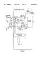
- FIG. 1is a block diagram showing an image management system according to the present invention
- FIG. 2is block diagram showing the switching control of the image management system of FIG. 1 in more detail
- FIG. 3is a schematic diagram of a video clamping and buffer stage for the image management system of FIG. 1;
- FIG. 4is a schematic diagram of the switching control aspect of the image management system depicted in FIG. 1.
- FIG. 1shows an image management system 10 according to the present invention.
- the image management system 10is also referred to as an image manager 10.
- the image management system 10is connected to an ultrasound station 12 and to a Review/Archive station 14, for example a remote PACS (Picture Archive Communications System).
- a remote PACSPicture Archive Communications System
- the image management system 10provides the ultrasound station 12 with DICOM3 or DEFF compatibility, i.e. the capability to produce ultrasound image files in the DICOM3 or DEFF formats.
- the image manager 10also allows the ultrasound station 12 to connect to the DICOM3 (or DEFF) compatible Review/Archive station 14 through a communication link or network 16, e.g. Ethernet.
- the image management system 10allows the ultrasound station 12 to operate independently, i.e. as a stand-alone ultrasound console located in an examination room of a hospital with a local or "micro-PACS" capability as will be described in more detail below.
- the ultrasound station 12is a well-known device and comprises an ultrasound machine 18 and a display monitor 20.
- the ultrasound machine 18uses ultrasonic waves for scanning a patient's body for medical diagnosis, e.g. prenatal care.
- the scan signalsare translated into a 2-dimensional digital image which is then converted into an analog video output signal 22 on video-out port 23 for display on the monitor 20.
- the analog video output signal 22includes an associated synchronization signal (not shown).
- Ultrasound machines known in the arttypically produce a video output based on the RGB, NTSC or PAL standards as will be understood by those skilled in the art.
- the display monitor 20has a video-in port 24 for receiving the analog video output signal 22.
- the video-out port 23(and analog video output signal 22) is coupled directly to the video-in port 24 on the monitor 20 for the ultrasound station 12.
- the analog video signal 22is coupled to a video input port 26 on the image manager 10.
- the video input port 26is connected to a switching stage 28 which is coupled to a frame buffer 30.
- the switching stage 28has an output which forms a video output port 32.
- the video output port 32is connected to the video-in port 24 on the ultrasound monitor 20.
- the frame buffer 30provides one of the inputs (output video signal 25) to the switching stage 28 and the video-out port 23 from the ultrasound machine 18 provides another input, i.e. the analog video signal 22.
- the switching stage 28controls the input source for the ultrasound monitor 20 by switching between the analog signal 22 or the output video signal 25 generated by the frame buffer 30.
- the default state for the switching stage 28is loop-back mode, i.e. switching the analog video signal 22 directly to the video-in port 24 on the ultrasound monitor 20. Because the video signal 22 is looped directly back to the monitor 20, the image manager 10 minimizes artifacts in the images displayed on the monitor 20. Artifacts arise from analog-to-digital conversions, for example, due to quantization error.
- the analog video signal 22is fed to the frame buffer 30 through a video buffer 34.
- the output of the frame buffer 30is connected to the switching stage 28 through another video buffer 36.
- the video buffers 34,36buffer the respective video signals 22,23 and prevent loading.
- the frame buffer 30digitizes the analog video signal 22 from the ultrasound machine 28 and stores the digitized ultrasound images or frames in local memory. The digitized images can be recalled by the operator for display on the monitor 20.
- the local memorycomprises resident memory (not shown) in the frame buffer 30 and a mass storage device and control logic to provide local image archive and database storage 38.
- the frame buffer 30comprises one of the IMAGSCANTM family of products available from Imagraph of Boston, Mass.
- the frame buffer 30preferably includes the capability to produce ultrasound image scan files in the DICOM3 and DEFF formats.
- the configuration of the frame buffer 30is within the understanding of one skilled the art. According to the invention, the frame buffer 30 is synchronized with the digital sampling rate, i.e. pixel frequency, of the scan converter in the ultrasound machine 18.
- the image manager 10includes a communications input/output port 40, for example, based on the industry-standard Ethernet protocol.
- the Ethernet standardis preferable for interfacing to PACS which utilize the same.
- the communications port 40allows the image manager 10 and ultrasound station 12 to be connected to a Review/Archive station 14 and/or networked with an ultrasound management system, for example, comprising a number of ultrasound stations and one or more PACS.
- the image manager 10includes other ports for connecting to a variety of peripherals.
- the image manager 10has an optical drive input/output port 42 for connecting to a Magneto Optical Drive (MOD) 44.
- the interface 42 and MOD 44provide the manager 10 with a substantial local archive and review or PACS (Picture Archive and Communications System) capability, thereby allowing the image manager 10 to be combined with an ultrasound 12 to form a stand-alone ultrasound management system suitable for smaller hospitals or medical clinics, i.e. storage and retrieval of ultrasound images in DICOM3 or DEFF format.
- PACSPicture Archive and Communications System
- the local archive and review capability of the image manager 10may be further augmented by a CD ROM device 45.
- the image manager 10includes a SCSI (Small Computer Systems Interface) port 46 which is suitable for use with a standard digital colour printer 48 and other SCSI compatible devices.
- the image manager 10also includes an auxiliary video port 50.
- the auxiliary video port 50comprises a video output 52 for a colour printer 54; a video output 56 for a video cassette recorder 58; a video output (black and white) 60 for a high definition multi-format camera 62; and a video output 64 for a black and white printer 66.
- the image manager 10also includes a video output 68 for a high resolution laser camera 70.
- the laser camera 70is a known device which generates high definition slides that are viewed with the aid of a light box.
- the digital communications port 40is used to control the operation of the laser camera 70 and the implementation of the port 40 will depend on the specifications of the particular laser camera 70 being utilized, for example, known laser cameras use an Ethernet interface.
- the operation of the image manager 10is controlled by a microcomputer.
- the image manager 10includes a keypad 72 and a foot switch 74 for accepting commands from an ultrasound technician or hospital professional. For example, the operator will use the keypad 72 to retrieve captured images from the frame buffer 30 for display on the monitor 20.
- FIG. 2shows the switching stage 28 and video buffers 34,36 in more detail.
- the analog video signal 22 on the video-out port 23is generated by the ultrasound machine 18 and comprise a RGB, NTSC or PAL standard. For convenience a single line is shown in FIG. 2.
- the image manager 10includes a video clamp stage 72 which is coupled between the video buffer 34 and the video-out port 23 on the ultrasound machine 18.
- the function of the clamp stage 72is to clamp or limit the voltage level of the analog signal 22 in order to protect the analog-to-digital converter on the input of the frame buffer 30.
- a video signalis typically 0.7 Volts.
- the clamp stage 72clamps the input video signal 22 at approximately 1.2 Volts.
- the implementation of the clamp stage 72is within the understanding of those skilled in the art and shown in more detail in FIG. 3.
- the implementation of the video buffer stage 34is also shown in FIG. 3.
- the video buffer stage 34comprises video amplifiers 34a, 34b, 34c for R, G, B, signals comprising the analog video signal 22.
- the video amplifiers 34a, 34b, 34care configured as unity gain buffers as will be within the understanding of those skilled in the art.
- a suitable component for the video buffers 34is the LM6181N Video Amplifier available from National Semiconductor of Santa Clara, Calif.
- the image manager 10includes a synchronization logic stage 74.
- the sync logic stage 74is coupled to the sync output 76 on the ultrasound machine 18.
- the function of the sync logic stage 74is to generate a synchronization signal 78 associated with the video output signal 25 produced by the frame buffer 30 so that the video signal 25 is compatible with the monitor 20.
- the sync logic stage 74is configured to generate SYNC, Composite Sync (i.e. Horizontal Sync and Vertical Sync), and Sync-on-Green synchronization signals 78.
- the sync logic stage 74is shown in detail in FIG. 4.
- the sync logic stage 74includes two EXOR logic gates 75a,75b which generate a composite sync signal 78a from the Horizontal Sync and Vertical Sync.
- the sync logic stage 78also includes an analog adder circuit 77 to generate a sync-on-green signal 78b by adding the sync signal with the green video signal as will be understood by one skilled in the art.
- the sync logic 78also includes a buffer 79 for buffering the sync signal 78.
- the appropriate sync signal 78,78a or 78bis connected to an input on the switching stage 28 using a jumper.
- the signal leveli.e.
- the switching stage 28controls the source of the sync signal 78, i.e. from the sync out 76 on the ultrasound machine in loop-back mode or from the frame buffer 30 for the output video 25.
- the switching stage 28comprises a switch 80 for switching the video signal source and a switch 82 for switching the sync signal source.
- the switching stage 28includes a pair of switches 84,86 for impedance matching with the ultrasound monitor 20.
- the switches 80 to 86are implemented using a bank of relays as shown in FIG. 4.
- the switching stage 28is coupled to and controlled by a microcomputer through a digital control interface 88.
- the digital control interface 88is coupled to the microcomputer bus as a memory-mapped peripheral.
- the implementation of the digital control interface 88is within the understanding of one skilled in the art and shown in more detail in FIG. 4.
- the first switch 80controls the video source to the ultrasound monitor 20.
- One input 80a of the switch 80is connected to the video-out port 23 of the ultrasound 18 and receives the analog video signal 22.
- the other input 80b of the switch 80is connected to the output of the frame buffer 30 through the video buffer 36 and receives the output video signal 25.
- the second switch 82controls the sync signal source for the ultrasound monitor 20.
- One input 82a of the switch 82is connected to the sync-out port 76 on the ultrasound machine 18 and receives the sync signal associated with the analog video signal 22.
- the other input 82b of the switch 82is connected to the output of the sync logic stage 74 and receives the sync signal 78 associated with the output video signal 25.
- user commandse.g.
- the microcomputerthrough the digital control interface 88 activates the switches 80,82 to change the video/sync source for the monitor 20.
- the default state for the switches 80,82is loop-back mode, i.e. the analog video signal 22 and sync signal is looped directly back to the video-in port 24 and sync-in port on the ultrasound monitor 20. This ensures that should the image manager 10 or network go down, the ultrasound station 12 can maintain normal operation.
- the third and fourth switches 84,86provide impedance matching for the ultrasound monitor 20. Because the ultrasound images are used for medical diagnosis, it is critical that the integrity of the analog video signal 22 and video output signal 25 be maintained. Impedance matching is important for maintaining the signal integrity and minimizing noise in the loop-back mode. As shown in FIG. 2, the switch 84 is coupled to a resistor 90. The resistance value for the resistor 90 depends on the specifications of the monitor 20. The switch 86 is also coupled to a resistor 92. In the loop-back mode, the switch 84 couples the resistor 90 to the video-in port 24 so that the monitor 20 sees a 75 Ohm impedance. The other switch 86 couples the output of the video buffer 36 to ground through the resistor 92 in order to minimize noise which may be coupled by the video-in port 24 and corrupt the video signal 22 being switched to the ultrasound monitor 20.
- a medical technicianuses the ultrasound station 12 to scan a patient, for example, an expectant mother.
- the ultrasound 12generates the video output signal 22, and in loop-back mode the video output 22 is displayed on the monitor 20.
- the video output signal 22is also fed to the frame buffer 30 through the video buffer 34 and digitized in the background by the image manager 10.
- the medical technicianuses the keypad 72 to switch between the display of the image produced by the ultrasound station 12 or the digital images stored in the frame buffer 30.
- the medical technicianmay direct the digital images from the image manager 10 to any one of the peripherals, e.g. the laser camera 70 or for long-term storage and retrieval to the MOD 44 or archive station 14 in a networked system.
- the analog video output signal 22is routed directly (i.e. without passing through the frame buffer 30) to the video-in port 24 on the monitor 20 in order to maintain the integrity of the ultrasound image. This is important because the interpretation of ultrasound images depends largely on an operator's ability to distinguish subtle textures and features in the image being displayed on the ultrasound monitor 20 and changes introduced to the image may affect the operator's interpretation.
Landscapes
- Engineering & Computer Science (AREA)
- Physics & Mathematics (AREA)
- Radar, Positioning & Navigation (AREA)
- Remote Sensing (AREA)
- Computer Networks & Wireless Communication (AREA)
- General Physics & Mathematics (AREA)
- Databases & Information Systems (AREA)
- Acoustics & Sound (AREA)
- Theoretical Computer Science (AREA)
- Data Mining & Analysis (AREA)
- General Engineering & Computer Science (AREA)
- Ultra Sonic Daignosis Equipment (AREA)
Abstract
Description
Claims (16)
Priority Applications (2)
| Application Number | Priority Date | Filing Date | Title |
|---|---|---|---|
| US08/547,266US5959678A (en) | 1995-10-24 | 1995-10-24 | Ultrasound image management system |
| US08/980,413US5949491A (en) | 1995-10-24 | 1997-11-28 | Ultrasound image management system |
Applications Claiming Priority (1)
| Application Number | Priority Date | Filing Date | Title |
|---|---|---|---|
| US08/547,266US5959678A (en) | 1995-10-24 | 1995-10-24 | Ultrasound image management system |
Related Child Applications (1)
| Application Number | Title | Priority Date | Filing Date |
|---|---|---|---|
| US08/980,413Continuation-In-PartUS5949491A (en) | 1995-10-24 | 1997-11-28 | Ultrasound image management system |
Publications (1)
| Publication Number | Publication Date |
|---|---|
| US5959678Atrue US5959678A (en) | 1999-09-28 |
Family
ID=24184009
Family Applications (1)
| Application Number | Title | Priority Date | Filing Date |
|---|---|---|---|
| US08/547,266Expired - LifetimeUS5959678A (en) | 1995-10-24 | 1995-10-24 | Ultrasound image management system |
Country Status (1)
| Country | Link |
|---|---|
| US (1) | US5959678A (en) |
Cited By (10)
| Publication number | Priority date | Publication date | Assignee | Title |
|---|---|---|---|---|
| US6210327B1 (en)* | 1999-04-28 | 2001-04-03 | General Electric Company | Method and apparatus for sending ultrasound image data to remotely located device |
| US6256686B1 (en)* | 1998-04-21 | 2001-07-03 | Grass Valley (Us) Inc. | Bi-directional serial video port |
| US20020099569A1 (en)* | 2000-08-04 | 2002-07-25 | Connex Md, Inc. | System and method for adaptive transmission of information |
| US6434569B1 (en)* | 1996-06-06 | 2002-08-13 | Kabushiki Kaisha Toshiba | Integrated medical information system formed of text-based and image-based databases, and display thereof |
| US20030002748A1 (en)* | 2001-04-16 | 2003-01-02 | Fuji Photo Film Co., Ltd. | Image management system, image management method and image display device |
| US6678703B2 (en) | 2000-06-22 | 2004-01-13 | Radvault, Inc. | Medical image management system and method |
| US6718192B1 (en) | 1999-11-24 | 2004-04-06 | Ge Medical Systems Global Technology Company, Llc | Method and apparatus for real-time 3D image rendering on a picture archival and communications system (PACS) workstation |
| US20040184643A1 (en)* | 2003-03-21 | 2004-09-23 | Stantchev Gueorgui H. | Methods and apparatus for imaging |
| US6834374B1 (en)* | 1998-12-28 | 2004-12-21 | Sanyo Electric Co., Ltd. | Audio-video control system |
| US7013032B1 (en) | 1999-11-24 | 2006-03-14 | The General Electric Company | Method and apparatus for secondary capture of 3D based images on a picture archival and communications (PACS) system |
Citations (4)
| Publication number | Priority date | Publication date | Assignee | Title |
|---|---|---|---|---|
| US5322066A (en)* | 1992-05-22 | 1994-06-21 | Shimadzu Corporation | Discretely modifiable imaging in ultrasonic diagnostic equipment |
| US5469353A (en)* | 1993-11-26 | 1995-11-21 | Access Radiology Corp. | Radiological image interpretation apparatus and method |
| US5528302A (en)* | 1995-08-31 | 1996-06-18 | University Of Washington | Real-time ultrasound scan conversion |
| US5586160A (en)* | 1995-03-20 | 1996-12-17 | The Regents Of The University Of California | Automated analysis for microcalcifications in high resolution digital mammograms |
- 1995
- 1995-10-24USUS08/547,266patent/US5959678A/ennot_activeExpired - Lifetime
Patent Citations (4)
| Publication number | Priority date | Publication date | Assignee | Title |
|---|---|---|---|---|
| US5322066A (en)* | 1992-05-22 | 1994-06-21 | Shimadzu Corporation | Discretely modifiable imaging in ultrasonic diagnostic equipment |
| US5469353A (en)* | 1993-11-26 | 1995-11-21 | Access Radiology Corp. | Radiological image interpretation apparatus and method |
| US5586160A (en)* | 1995-03-20 | 1996-12-17 | The Regents Of The University Of California | Automated analysis for microcalcifications in high resolution digital mammograms |
| US5528302A (en)* | 1995-08-31 | 1996-06-18 | University Of Washington | Real-time ultrasound scan conversion |
Non-Patent Citations (1)
| Title |
|---|
| Product Brochure for Access Acquisition Module and Image Management System by Advanced Technology Laboratories Undated.* |
Cited By (11)
| Publication number | Priority date | Publication date | Assignee | Title |
|---|---|---|---|---|
| US6434569B1 (en)* | 1996-06-06 | 2002-08-13 | Kabushiki Kaisha Toshiba | Integrated medical information system formed of text-based and image-based databases, and display thereof |
| US6256686B1 (en)* | 1998-04-21 | 2001-07-03 | Grass Valley (Us) Inc. | Bi-directional serial video port |
| US6834374B1 (en)* | 1998-12-28 | 2004-12-21 | Sanyo Electric Co., Ltd. | Audio-video control system |
| US6210327B1 (en)* | 1999-04-28 | 2001-04-03 | General Electric Company | Method and apparatus for sending ultrasound image data to remotely located device |
| US6718192B1 (en) | 1999-11-24 | 2004-04-06 | Ge Medical Systems Global Technology Company, Llc | Method and apparatus for real-time 3D image rendering on a picture archival and communications system (PACS) workstation |
| US7013032B1 (en) | 1999-11-24 | 2006-03-14 | The General Electric Company | Method and apparatus for secondary capture of 3D based images on a picture archival and communications (PACS) system |
| US6678703B2 (en) | 2000-06-22 | 2004-01-13 | Radvault, Inc. | Medical image management system and method |
| US20020099569A1 (en)* | 2000-08-04 | 2002-07-25 | Connex Md, Inc. | System and method for adaptive transmission of information |
| US20030002748A1 (en)* | 2001-04-16 | 2003-01-02 | Fuji Photo Film Co., Ltd. | Image management system, image management method and image display device |
| US7062105B2 (en)* | 2001-04-16 | 2006-06-13 | Fuji Photo Film Co., Ltd. | Image management system, image management method and image display device |
| US20040184643A1 (en)* | 2003-03-21 | 2004-09-23 | Stantchev Gueorgui H. | Methods and apparatus for imaging |
Similar Documents
| Publication | Publication Date | Title |
|---|---|---|
| US5949491A (en) | Ultrasound image management system | |
| US5592237A (en) | High resolution image processor with multiple bus architecture | |
| US6778208B2 (en) | Electronic endoscope system | |
| US4764870A (en) | System and method for remote presentation of diagnostic image information | |
| US6791601B1 (en) | Multi-function image and video capture device for use in an endoscopic camera system | |
| US6774930B2 (en) | Image processing unit for expanding endoscope image signal processing capability | |
| US7821529B2 (en) | Image pickup system | |
| US6230043B1 (en) | Method and apparatus for capturing and automatically transferring an x-ray image to a remote location | |
| US5959678A (en) | Ultrasound image management system | |
| JPH04987A (en) | Endoscope image filing system | |
| GB2288511A (en) | Diagnostic method and apparatus | |
| US5902230A (en) | Electronic endoscope system with information combined in digital output | |
| JP3510733B2 (en) | Video signal processing device connectable to electronic endoscope | |
| CA2157150C (en) | Ultrasound image management system | |
| JP3034747B2 (en) | Ultrasound diagnostic equipment | |
| US5914755A (en) | Image transmission apparatus | |
| JPH0552215B2 (en) | ||
| JPH1199125A (en) | Endoscope image filing system | |
| JP3331142B2 (en) | Electronic endoscope device | |
| US5777683A (en) | Ultrasonic imaging system adopting a non-interlaced scanning method | |
| JPH02191424A (en) | Video endoscopic apparatus | |
| JP2021125814A (en) | Medical image processing system and encoding device | |
| JPH08154244A (en) | Image storage | |
| JP5089838B2 (en) | Endoscope device | |
| Wootton | Equipment for minor injuries telemedicine |
Legal Events
| Date | Code | Title | Description |
|---|---|---|---|
| AS | Assignment | Owner name:DICOMIT IMAGING SYSTEMS CORP, CANADA Free format text:ASSIGNMENT OF ASSIGNORS INTEREST;ASSIGNORS:CALLAHAN, TERRANCE;HIRSON, DESMOND;REEL/FRAME:007964/0205 Effective date:19951003 | |
| AS | Assignment | Owner name:DICOMIT IMAGING SYSTEMS CORP., CANADA Free format text:ASSIGNMENT OF ASSIGNORS INTEREST;ASSIGNOR:DICOMIT IMAGING INC.;REEL/FRAME:008623/0057 Effective date:19970722 | |
| STCF | Information on status: patent grant | Free format text:PATENTED CASE | |
| AS | Assignment | Owner name:DICOMIT DICOM INFORMATION TECHNOLOGIES CORP., ONTA Free format text:ASSIGNMENT OF ASSIGNORS INTEREST;ASSIGNOR:DICOMIT IMAGING SYSTEMS CORP.;REEL/FRAME:010371/0424 Effective date:19990830 | |
| FEPP | Fee payment procedure | Free format text:PAYOR NUMBER ASSIGNED (ORIGINAL EVENT CODE: ASPN); ENTITY STATUS OF PATENT OWNER: LARGE ENTITY Free format text:PAT HOLDER NO LONGER CLAIMS SMALL ENTITY STATUS, ENTITY STATUS SET TO UNDISCOUNTED (ORIGINAL EVENT CODE: STOL); ENTITY STATUS OF PATENT OWNER: LARGE ENTITY | |
| AS | Assignment | Owner name:ANALOGIC CORPORATION, MASSACHUSETTS Free format text:SECURITY INTEREST;ASSIGNOR:CEDARA SOFTWARE CORP.;REEL/FRAME:013804/0536 Effective date:20030203 Owner name:NATIONAL BANK OF CANADA, CANADA Free format text:SECURITY INTEREST;ASSIGNOR:CEDARA SOFTWARE CORP.;REEL/FRAME:013804/0536 Effective date:20030203 | |
| FPAY | Fee payment | Year of fee payment:4 | |
| AS | Assignment | Owner name:CEDARA SOFTWARE CORP., CANADA Free format text:MERGER;ASSIGNOR:DICOMIT DICOM INFORMATION TECHNOLOGIES CORP.;REEL/FRAME:014692/0283 Effective date:20020701 | |
| AS | Assignment | Owner name:CEDARA SOFTWARE CORP., ONTARIO Free format text:RELEASE BY SECURED PARTY;ASSIGNOR:ANALOGIC CORPORATION;REEL/FRAME:018247/0347 Effective date:20040630 Owner name:CEDARA SOFTWARE CORP., ONTARIO Free format text:RELEASE BY SECURED PARTY;ASSIGNOR:NATIONAL BANK OF CANADA;REEL/FRAME:018247/0396 Effective date:20041006 | |
| FEPP | Fee payment procedure | Free format text:PAYER NUMBER DE-ASSIGNED (ORIGINAL EVENT CODE: RMPN); ENTITY STATUS OF PATENT OWNER: LARGE ENTITY Free format text:PAYOR NUMBER ASSIGNED (ORIGINAL EVENT CODE: ASPN); ENTITY STATUS OF PATENT OWNER: LARGE ENTITY | |
| FEPP | Fee payment procedure | Free format text:PAYER NUMBER DE-ASSIGNED (ORIGINAL EVENT CODE: RMPN); ENTITY STATUS OF PATENT OWNER: LARGE ENTITY Free format text:PAYOR NUMBER ASSIGNED (ORIGINAL EVENT CODE: ASPN); ENTITY STATUS OF PATENT OWNER: LARGE ENTITY | |
| FPAY | Fee payment | Year of fee payment:8 | |
| AS | Assignment | Owner name:MERRICK RIS, LLC, ILLINOIS Free format text:SECURITY AGREEMENT;ASSIGNOR:CEDARA SOFTWARE CORP.;REEL/FRAME:021085/0154 Effective date:20080604 | |
| FEPP | Fee payment procedure | Free format text:PAYER NUMBER DE-ASSIGNED (ORIGINAL EVENT CODE: RMPN); ENTITY STATUS OF PATENT OWNER: LARGE ENTITY Free format text:PAYOR NUMBER ASSIGNED (ORIGINAL EVENT CODE: ASPN); ENTITY STATUS OF PATENT OWNER: LARGE ENTITY | |
| FEPP | Fee payment procedure | Free format text:PAYER NUMBER DE-ASSIGNED (ORIGINAL EVENT CODE: RMPN); ENTITY STATUS OF PATENT OWNER: LARGE ENTITY Free format text:PAYOR NUMBER ASSIGNED (ORIGINAL EVENT CODE: ASPN); ENTITY STATUS OF PATENT OWNER: LARGE ENTITY | |
| FPAY | Fee payment | Year of fee payment:12 | |
| AS | Assignment | Owner name:JEFFERIES FINANCE LLC, NEW YORK Free format text:SECURITY AGREEMENT;ASSIGNORS:MERGE HEALTHCARE INCORPORATED;MERGE ASSET MANAGEMENT CORP.;MERGE ECLINICAL INC.;AND OTHERS;REEL/FRAME:030281/0510 Effective date:20130423 | |
| AS | Assignment | Owner name:MERGE HEALTHCARE SOLUTIONS INC., WISCONSIN Free format text:TERMINATION AND RELEASE OF SECURITY INTEREST (PATENTS) (REEL 030281/FRAME 0510);ASSIGNOR:JEFFERIES FINANCE LLC, AS COLLATERAL AGENT;REEL/FRAME:032784/0850 Effective date:20140429 Owner name:MERGE ECLINICAL INC., WISCONSIN Free format text:TERMINATION AND RELEASE OF SECURITY INTEREST (PATENTS) (REEL 030281/FRAME 0510);ASSIGNOR:JEFFERIES FINANCE LLC, AS COLLATERAL AGENT;REEL/FRAME:032784/0850 Effective date:20140429 Owner name:MERGE SH HOLDINGS, INC., WISCONSIN Free format text:TERMINATION AND RELEASE OF SECURITY INTEREST (PATENTS) (REEL 030281/FRAME 0510);ASSIGNOR:JEFFERIES FINANCE LLC, AS COLLATERAL AGENT;REEL/FRAME:032784/0850 Effective date:20140429 Owner name:MERGE ASSET MANAGEMENT CORP., WISCONSIN Free format text:TERMINATION AND RELEASE OF SECURITY INTEREST (PATENTS) (REEL 030281/FRAME 0510);ASSIGNOR:JEFFERIES FINANCE LLC, AS COLLATERAL AGENT;REEL/FRAME:032784/0850 Effective date:20140429 Owner name:MERGE INTERACTIVE, INCORPORATED, WISCONSIN Free format text:TERMINATION AND RELEASE OF SECURITY INTEREST (PATENTS) (REEL 030281/FRAME 0510);ASSIGNOR:JEFFERIES FINANCE LLC, AS COLLATERAL AGENT;REEL/FRAME:032784/0850 Effective date:20140429 Owner name:GUGGENHEIM CORPORATE FUNDING, LLC, AS COLLATERAL A Free format text:PATENT SECURITY AGREEMENT;ASSIGNORS:MERGE HEALTHCARE INCORPORATED;MERGE ASSET MANAGEMENT CORP.;MERGE ECLINICAL INC.;AND OTHERS;REEL/FRAME:032784/0644 Effective date:20140429 Owner name:REQUISITE SOFTWARE INC., WISCONSIN Free format text:TERMINATION AND RELEASE OF SECURITY INTEREST (PATENTS) (REEL 030281/FRAME 0510);ASSIGNOR:JEFFERIES FINANCE LLC, AS COLLATERAL AGENT;REEL/FRAME:032784/0850 Effective date:20140429 Owner name:MERGE HEALTHCARE INCORPORATED, ILLINOIS Free format text:TERMINATION AND RELEASE OF SECURITY INTEREST (PATENTS) (REEL 030281/FRAME 0510);ASSIGNOR:JEFFERIES FINANCE LLC, AS COLLATERAL AGENT;REEL/FRAME:032784/0850 Effective date:20140429 Owner name:MERGE SF HOLDINGS, INC., WISCONSIN Free format text:TERMINATION AND RELEASE OF SECURITY INTEREST (PATENTS) (REEL 030281/FRAME 0510);ASSIGNOR:JEFFERIES FINANCE LLC, AS COLLATERAL AGENT;REEL/FRAME:032784/0850 Effective date:20140429 | |
| AS | Assignment | Owner name:ULTRAVISUAL MEDICAL SYSTEMS CORPORATION, WISCONSIN Free format text:RELEASE BY SECURED PARTY;ASSIGNOR:GUGGENHEIM CORPORATE FUNDING, LLC;REEL/FRAME:036874/0234 Effective date:20151013 Owner name:MERGE SH HOLDINGS, INC., WISCONSIN Free format text:RELEASE BY SECURED PARTY;ASSIGNOR:GUGGENHEIM CORPORATE FUNDING, LLC;REEL/FRAME:036874/0234 Effective date:20151013 Owner name:MERGE HEALTHCARE SOLUTIONS INC., WISCONSIN Free format text:RELEASE BY SECURED PARTY;ASSIGNOR:GUGGENHEIM CORPORATE FUNDING, LLC;REEL/FRAME:036874/0234 Effective date:20151013 Owner name:REQUISITE SOFTWARE, INC., WISCONSIN Free format text:RELEASE BY SECURED PARTY;ASSIGNOR:GUGGENHEIM CORPORATE FUNDING, LLC;REEL/FRAME:036874/0234 Effective date:20151013 Owner name:CEDARA SOFTWARE CORP., WISCONSIN Free format text:RELEASE BY SECURED PARTY;ASSIGNOR:GUGGENHEIM CORPORATE FUNDING, LLC;REEL/FRAME:036874/0234 Effective date:20151013 Owner name:MERGE HEALTHCARE INCORPORATED, WISCONSIN Free format text:RELEASE BY SECURED PARTY;ASSIGNOR:GUGGENHEIM CORPORATE FUNDING, LLC;REEL/FRAME:036874/0234 Effective date:20151013 Owner name:MERGE ECLINICAL, INC., WISCONSIN Free format text:RELEASE BY SECURED PARTY;ASSIGNOR:GUGGENHEIM CORPORATE FUNDING, LLC;REEL/FRAME:036874/0234 Effective date:20151013 | |
| AS | Assignment | Owner name:MERRICK RIS, LLC, ILLINOIS Free format text:RELEASE BY SECURED PARTY;ASSIGNOR:CEDARA SOFTWARE CORP.;REEL/FRAME:049391/0973 Effective date:20080604 | |
| AS | Assignment | Owner name:CEDARA SOFTWARE CORP., CANADA Free format text:CORRECTIVE ASSIGNMENT TO CORRECT THE CONVEYING AND RECEIVING PARTIES PREVIOUSLY RECORDED AT REEL: 049391 FRAME: 0973. ASSIGNOR(S) HEREBY CONFIRMS THE RELEASE OF SECURITY INTEREST;ASSIGNOR:MERRICK RIS, LLC;REEL/FRAME:050263/0804 Effective date:20190513 | |
| AS | Assignment | Owner name:INTERNATIONAL BUSINESS MACHINES CORPORATION, NEW YORK Free format text:ASSIGNMENT OF ASSIGNORS INTEREST;ASSIGNOR:MERGE HEALTHCARE CANADA CORP.;REEL/FRAME:055603/0514 Effective date:20210316 | |
| AS | Assignment | Owner name:MERGE HEALTHCARE CANADA CORP., CANADA Free format text:CHANGE OF NAME;ASSIGNOR:CEDARA SOFTWARE CORP;REEL/FRAME:055833/0069 Effective date:20111121 |