US5959660A - Subchannelization scheme for use in a broadband communications system - Google Patents
Subchannelization scheme for use in a broadband communications systemDownload PDFInfo
- Publication number
- US5959660A US5959660AUS08/702,932US70293296AUS5959660AUS 5959660 AUS5959660 AUS 5959660AUS 70293296 AUS70293296 AUS 70293296AUS 5959660 AUS5959660 AUS 5959660A
- Authority
- US
- United States
- Prior art keywords
- signal
- client
- downconverter
- tuner
- signals
- Prior art date
- Legal status (The legal status is an assumption and is not a legal conclusion. Google has not performed a legal analysis and makes no representation as to the accuracy of the status listed.)
- Expired - Fee Related
Links
- 230000006854communicationEffects0.000titleclaimsabstractdescription26
- 238000004891communicationMethods0.000titleclaimsabstractdescription26
- 238000000034methodMethods0.000claimsabstractdescription15
- 238000011144upstream manufacturingMethods0.000claimsdescription51
- 238000011084recoveryMethods0.000claimsdescription13
- 230000005540biological transmissionEffects0.000claimsdescription8
- 238000001228spectrumMethods0.000claimsdescription2
- 230000008878couplingEffects0.000claims1
- 238000010168coupling processMethods0.000claims1
- 238000005859coupling reactionMethods0.000claims1
- 238000012546transferMethods0.000abstractdescription3
- 238000010586diagramMethods0.000description11
- 230000000694effectsEffects0.000description8
- 230000006735deficitEffects0.000description6
- 239000002131composite materialSubstances0.000description5
- 238000012360testing methodMethods0.000description5
- 238000007796conventional methodMethods0.000description4
- 238000010897surface acoustic wave methodMethods0.000description4
- 230000035945sensitivityEffects0.000description3
- 230000008901benefitEffects0.000description2
- 230000007175bidirectional communicationEffects0.000description2
- 238000005070samplingMethods0.000description2
- 239000000969carrierSubstances0.000description1
- 230000003750conditioning effectEffects0.000description1
- 238000013500data storageMethods0.000description1
- 238000005516engineering processMethods0.000description1
- 238000007726management methodMethods0.000description1
- 238000012545processingMethods0.000description1
- 230000035755proliferationEffects0.000description1
- 238000007493shaping processMethods0.000description1
- 230000001360synchronised effectEffects0.000description1
Images


Classifications
- H—ELECTRICITY
- H04—ELECTRIC COMMUNICATION TECHNIQUE
- H04N—PICTORIAL COMMUNICATION, e.g. TELEVISION
- H04N7/00—Television systems
- H04N7/12—Systems in which the television signal is transmitted via one channel or a plurality of parallel channels, the bandwidth of each channel being less than the bandwidth of the television signal
- H—ELECTRICITY
- H04—ELECTRIC COMMUNICATION TECHNIQUE
- H04L—TRANSMISSION OF DIGITAL INFORMATION, e.g. TELEGRAPHIC COMMUNICATION
- H04L12/00—Data switching networks
- H04L12/28—Data switching networks characterised by path configuration, e.g. LAN [Local Area Networks] or WAN [Wide Area Networks]
- H04L12/2801—Broadband local area networks
- H—ELECTRICITY
- H04—ELECTRIC COMMUNICATION TECHNIQUE
- H04N—PICTORIAL COMMUNICATION, e.g. TELEVISION
- H04N7/00—Television systems
- H04N7/16—Analogue secrecy systems; Analogue subscription systems
- H04N7/173—Analogue secrecy systems; Analogue subscription systems with two-way working, e.g. subscriber sending a programme selection signal
Definitions
- the present inventionrelates generally to subchannelization schemes in which a wide band data channel is segmented into plural narrow band subchannels, and more particularly, a method and apparatus for subchannelizing a standard television channel to permit data transfer over plural data channels of smaller bandwidth in a full-duplex, asymmetric hybrid network communication system.
- a television channel carrier signal in a communication networkfor the transmission of digital data is known.
- a cable modemfor example, is one application of this technology.
- the transmission of high speed digital data over a single television channelleaves the data carried on that channel very susceptible to interference and other noise which tend to degrade the quality of data being transmitted.
- the data rate of a network receiving such transmissionsdoes not necessarily match the maximum available data rate of the television channel and thus special hardware may be required to efficiently utilize the full bandwidth. Due to the proliferation of the Internet and intranets and an ever increasing demand for higher data throughput by client devices connected to such networks, methods and apparatuses for increasing quality throughput and reducing error rates are desirable.
- the present inventionprovides a method and apparatus for increasing the quality throughput of data transmitted in a network over a standard television channel and for providing an efficient scheme for subdividing the television channel into plural subchannels of data rates that match the data rate of the network to which client devices are connected.
- By subdividing a standard television channelone can reduce the overall effect of noise ingress, near-end cross talk, intermodulation, and sensitivity to frequency response on the client devices receiving data over the television channel.
- a further object of the present inventionis to reduce the effect of near-end cross talk on clients receiving data in a network over a standard television channel.
- Another object of the present inventionis to reduce the effect of intermodulation on clients receiving data in a network over a standard television channel.
- a further object of the present inventionis to reduce the effect of sensitivity to frequency response variations on clients receiving data in a network over a standard television channel.
- a further object of the present inventionis to improve the bit error rate of standard television channels used for transmission of digital data.
- a further object of an embodiment of the present inventionis to provide a data subchannel of a standard television channel whose throughput is approximately equal to the Ethernet 10 Mbit/sec standard.
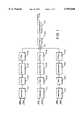
- FIG. 1is a block diagram of a channel divider according to an embodiment of the present invention
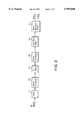
- FIG. 2is a block diagram of a data recovery device according to an embodiment of the present invention.
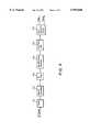
- FIG. 3is a block diagram of a channel divider according to another embodiment of the present invention.
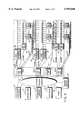
- FIG. 4is a block diagram of a data recovery device according to another embodiment of the present invention.
- FIG. 5is a block diagram of a hybrid access system in which the channelizer of the present invention may be employed
- FIG. 6ais a block diagram of a hybrid access system point of presence (POP) in which the channelizer of the present invention may be employed;
- POPpoint of presence
- FIG. 6bis a block diagram of a downstream router
- FIG. 6cis a block diagram of an upstream router
- FIGS. 7a, b and care block diagrams of a hybrid access system depicting upstream channels and high speed downstream links to respective client devices in which an embodiment of the present invention is employed.
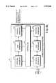
- FIG. 1depicts a three-way channelizer in which a broadband television channel (6 Mhz wide in the United States) is subdivided into three 2 Mhz data channels.
- the channelization schemesmay also be altered to accommodate 8 Mhz channels utilized in Europe and elsewhere.
- three digital data serial streamseach of preferably about 10 Mbits/sec, e.g., a conventional 10BaseT LAN data rate, are input into three modulators 101A-C.
- the modulatorsuse a common clock to modulate three data input streams by quadrature amplitude modulation (QAM).
- QAMquadrature amplitude modulation
- Other forms of modulationsuch as vestigial side band (e.g., 4 VSB or 8 VSB modulation), may be used.
- 64 QAM modulationprovides a data throughput of about 1.536 or 1.648 megasymbols per second per subchannel.
- each of the modulated data streamsare low pass filtered by filters 102A-C.
- Filters 102A-Care preferably elliptically-shaped Butterworth filters having 7 or 9 poles and a cut-off frequency of about 2.5 MHz.
- the three filtered signalsare then upconverted in upconverters 103A-C using conventional techniques.
- the upconverters 103A-Cupconvert the signals to intermediate frequency (IF) signals centered about 42 MHz (subchannel A), 44 MHz (subchannel B) and 46 MHz (subchannel C), respectively.
- IFintermediate frequency
- the reason that the data streams are modulated and later upconvertedis that present circuit limitations prevent direct modulation using 64 QAM. It is to be understood that the scope of the present invention does not exclude direct QAM modulation to intermediate frequencies (IF) for further conditioning and processing by standard television components.
- IF filters 104A-Care 2 MHz wide surface-acoustic-wave (SAW) filters.
- SAWsurface-acoustic-wave
- IF filter 106The output of IF filter 106 is supplied to upconverter 107 where the IF composite signal is upconverted again using techniques common to standard television signals.
- the data recovery circuit of FIG. 2located at a receiving end of a data transmission, it is seen that data received from the network flows to a client over a specific subchannel.
- the particular subchannelis defined by the tuned frequency of tuner 111.
- the incoming RF signalsare supplied to the tuner 111 in which a specific 2 Mhz television subchannel frequency is selected (or tuned). For instance, tuner 111 may tune to the RF frequency of 55 MHz, representing subchannel A of television channel 2. That signal is then downconverted to an IF frequency centered at 44 MHz in downconverter 112 and run through an IF filter 113, preferably one matching IF filters 104A-C in FIG. 1.
- the filtered signalis then downconverted at downconverter 115 to baseband and filtered again at filter 116 preferably using a filter matching filters 102A-C used on the modulating end.
- the digital datais then recovered from the baseband signal in data recovery circuit 117 using conventional techniques such as baseband sampling at four, eight or sixteen times the symbol rate.
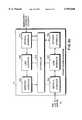
- three digital data serial streamspreferably each utilizing the same clock signal, are input into three modulators 121A-C.
- These modulators 121A-Cvestigial sideband modulate (VSB) the three input data streams by carriers of 42.950 MHz, 44.950 MHz and 46.950 MHz, respectively.
- VSBvestigial sideband modulate
- 4 VSBis utilized.
- any other acceptable form of modulationmay be used.
- IF filters 124A-Care 2 MHz wide surface-acoustic-wave (SAW) filters.
- IF filter 126The output of IF filter 126 is fed to upconverter 127 where the IF composite signal is upconverted again using conventional techniques to a common television channel carrier frequency.
- the datathen flows to a client over a specific subchannel.
- the incoming RF signalsare fed into a tuner 131 in which a specific television subchannel frequency is selected. That signal is then downconverted to an IF frequency centered at 44 MHz in downconverter 132 and run through an IF filter 133, preferably one matching IF filters 124A-C in FIG. 3.
- the filtered signalis then fed to synchronous detector 135 followed by low pass filter 136.
- Filter 136is preferably an elliptically-shaped Butterworth filter with 7 or 9 poles and a cut-off frequency of about 2.5 MHz.
- the digital datais then recovered from the baseband signal in data recovery circuit 137 using conventional techniques, such as sampling at two times the symbol rate.
- datamay be transmitted from a client to a television headend facility utilizing a television subchannel as well by modulating (as described above) a single data bit stream for transmission over a subchannel frequency.
- FIG. 5is a detailed schematic drawing of a hybrid access system 1 in which the subchannelizer and data recovery device is employed respectively at the cable television headend 28 and a the remote link adapters 29 in order to permit subdividing a standard 6 Mhz channel transmitted from headend 28 into three 2 Mhz subchannels that are conveyed over a high speed downstream channel to plural remote like adapters 29.
- FIG. 5shows a remote link adapter (RLA) and client workstation 29 connected through hybrid access system 1 to a variety of entities connected to a backbone network 20 such as Internet, including information providers 21, corporations 22, government agencies 23, universities 24, and others 25.
- a backbone networkis one which is typically not directly connected to a client.
- Hybrid access system 1includes hybrid access system (HAS) points of presence (POPs) 26 and other points of presence 27.
- HAS POPs 26include individual HAS POPs 26 (1)-26(3) which enable communication over a broadband network, either by upstream and downstream cable communications or by downstream cable and upstream telephone communications or various other hybrid configurations (e.g., wireless or satellite).
- a hybrid access system utilizing the present inventionmay include: (1) a hybrid access configuration which uses downstream cable television subchannels and upstream public switch telephone network (PSTN), wireless RF communications or integrated services digital network (ISDN) telephone lines; (2) a hybrid access configuration which uses downstream wireless television subchannels and upstream public switch telephone network (PSTN), wireless RF communications or integrated services digital network (ISDN) telephone lines; (3) a hybrid access configuration which uses both downstream and upstream cable television subchannels; (4) a hybrid access configuration which uses both downstream and upstream wireless television subchannels; and (5) a hybrid access configuration with downstream satellite television subchannels and upstream PSTN, wireless RF communications or ISDN telephone channels.
- PSTNpublic switch telephone network
- ISDNintegrated services digital network
- Backbone network 20such as the Internet which includes a plurality of Internet serves 20 connected to HAS POPs 26 each including a plurality of host computers and/or servers, collectively referred to as hybrid servers.
- Hybrid access system 1further includes broadcast units such as, a cable television headend 28, independent upstream channels 28, and RLA 29.
- broadcast unitssuch as, a cable television headend 28, independent upstream channels 28, and RLA 29.
- U.S. Pat. No. 5,347,304 (1994) assigned to Hybrid Networks, Inc., describing an example of an RLA,is hereby expressly referenced and incorporated herein in its entirety.
- An RLAmay receive analog broadcast signals including encoded digital information which the RLA decodes and provides to a data terminal or computer.
- the downstream flow of informationproceeds from HAS POPs 26(1)-26(3) through cable television headend or television transmitters 28 through television subchannels or cell sites 30 and through RLA and client workstation 29.
- Upstream information flowproceeds in one case from RLA and client workstation 29 through independent upstream channels 28 to HASPOP 26(1) and then to backbone network 20 along T1 or T3 or other digital lines.
- upstream informationproceeds from client workstation through RLA 29 through the cable television network, and cable television headend 28 to hybrid access system point of presence and then through T1, T3, or other digital lines to backbone network 20.
- the outputs of the cable television headends or television transmitters 28include pluralities of high speed downstream broadband radio frequency (RF) subchannels connected to respective remote clients 29.
- RFradio frequency
- Hybrid access system 1further includes a plurality of cell sites 30 connected through high speed links to a corresponding hybrid access system point of presence 5.
- the outputs of cell sites 30include pluralities of high speed downstream broadband subchannels connected to selected remote clients 29.
- a particular remote client 29can be connected via an independent lower speed upstream channel to a hybrid access system point of presence 26 as discussed below or via a similar independent lower speed upstream channel to another point of presence system 27.
- lower speedit is meant as a speed reduced from the speed of the high speed link used to transmit information downstream.
- a particular hybrid access system point of presence 5can be connected via duplex high speed links to a plurality of cable television headends or television transmitters, to a plurality of cell sites 30, or a combination of cable television headends or television transmitters 28 and cell sites 30.
- FIG. 6ais a schematic drawing of a point of presence (POP) system 26(1) according to the present invention, including host computers or servers 39 and a POP local area network, i.e., LAN switch 33 to which host computers or servers 39 are connected. Further connected to LAN switch 33 are one or more downstream and one or more upstream hybrid access system point of presence routers, respectively 34 and 35, one or more dial-up routers 36, a network management system 37, and conventional routers 38. Connected to POP LAN switch 33 are one or more data storage elements or systems (not shown). Each downstream hybrid access system point of presence router 34 is connected with a high speed link to a television transmitter or cable television headend for transmission of data over television subchannels, for example.
- POPpoint of presence
- each upstream hybrid access system point of presence router 35is connected to a plurality of independent upstream channels, which operate at a lower speed than the downstream high speed links to television transmitters or cable television headends.
- Each dial-up router 36is connected to a plurality of independent upstream channels operating at a lower speed than the indicated downstream high speed links.
- Each conventional router 38is connected along a high speed line to wide area network (WAN) lines to selected information providers, Internet, or other nodes or businesses.
- POP LAN switch 33may be connected directly along a high speed line to wide area network (WAN) lines to selected information providers, Internet, or other nodes or businesses.
- FIG. 6bis a block diagram of hybrid downstream router 34 for use with the present invention.
- downstream router 34includes network interface 34a, link interface 34F, and network interface 34g.
- Downstream router 34 and physical interface 34eare connected to POP LAN switch 33 for sending and receiving information, and physical interface 34e, link interface 34f, and network interface 34g are serially connected to each other and to controller 34d for bi-directional communication of selected information.
- controller 34dis connected directly to each of physical interface 34e and link interface 34f along indicated lines to accomplish control and messaging functions.
- Downstream router 34 and physical interface 34care connected to cable television headends, television broadcast sites, cell cites or the like, to communicate information primarily or exclusively in a unidirectional or downstream direction over television subchannels, and physical interface 34c, link interface 34b, and network interface 34a are serially connected to each other and to controller 34d for selected communication of selected information. Additionally, controller 34d is connected directly to each of physical interface 34c and link interface 34b along indicated lines to accomplish control and messaging functions. Downstream router 34 may include one or more of physical interfaces 34c. Router 34 may be a bridge without network interfaces 34a and 34g or a connection without network interfaces 34a and 34g and without link interfaces 34b and 34f. Router 34 can also be a gateway.
- FIG. 6cis a block diagram of upstream router 35 for use with the present invention.
- upstream router 35includes network interface 35a, link interface 35b, physical interface 35c, controller 35d, physical interface 35e, link interface 35f, and network interface 35g.
- Upstream router 35 and physical interface 35eare connected to POP LAN switch 33 for sending and receiving information, and physical interface 35e, link interface 35f, and network interface 35g are serially connected to each other and to controller 35d for bi-directional communication of selected information.
- controller 35dis connected directly to each other physical interface 35e and link interface 35f along indicated lines to accomplish control and messaging functions.
- Upstream router 35 and physical interface 35care connected to upstream channels, e.g.
- Upstream router 35may include one or more of physical interfaces 35c.
- Router 35may be a bridge without network interfaces 35a and 35g or a connection without network interfaces 35a and 35g and without link interfaces 35b and 35f. Router 35 can also be a gateway.
- FIGS. 7a-care drawings of a hybrid access system 1 in which a remote client having a workstation 2 is connected to LAN 61, as shown respectively in FIGS. 7b and 7c, can communicate with a selected information provider 21 including LAN 50, bridge or router 51 connected to LAN 50, and dial-up router 52 connected to LAN 50 through a hybrid access system point of presence 5.
- HAS POP 5is connected along a high speed link to bridge or router 51.
- HAS POP 5is linked to other information providers to receive selected information items.
- dial-up router 52is connected to a plurality of upstream channels.
- first and second clientsadditionally show respective first and second clients, in one case including workstation 2 which includes RLA 60 and in the other instance including RLA 60 and a local area network (LAN) 61 connected to RLA 60.
- First client 29(1)is connected to an upstream channel from client workstation 2
- second client 29(2)is connected to an upstream channel directly from RLA 60.
- RLA 60receives input information, particularly radio frequency (RF) information along one of respective input subchannels connected thereto.
- RFradio frequency
- channel impairmentsBy utilizing the present invention, the effects of channel impairments on a television channel utilized for transfer of high speed digital data can be dramatically improved. Without the use of the invention, channel impairments such as noise ingress, near-end cross talk, composite intermodulation, and poor frequency response can severely restrict the usable throughput on a channel.
- noise ingresstends to have a narrow band effect.
- the ingressaffects one of the subchannels rather than the entire channel.
- CWcontinuous wave
- the effects of near-end cross talkare reduced.
- Near-end cross talk interferencewhich appears as a continuous wave (CW) interferer, will also fall within one subchannel.
- sensitivity to intermodulationsuch as the composite second order or the composite triple beat, caused by nonlinearity in distribution amplifiers is improved.
- the main intermod impactis also placed in one of the subchannels.
- the same IF filter that would be utilized for data on a channelis utilized for data on the subchannel.
- the filter effectivenesswill be increased by the ratio of the channel size to the subchannel size.
- the filter effectivenesswould be increased threefold. This increase in effectiveness will yield better channel shaping and more effective cancellation of channel impairments. So not only would a smaller number of clients be affected by the channel impairments due to the containment of the impairments within single subchannels, the channel impairments would be better canceled.
- subchannelsAnother benefit of the use of subchannels is that the data rate approximately matches the 10 Mbit/sec standard Ethernet data rate. If subchannels are not used, special cards are needed to create a 30 Mbit/sec network.
- any standard television channelcould be subdivided (such as a European 8 MHz channel) and can be subdivided into any size subchannel.
- subchannelsneed not be of uniform bandwidth. For example, a 6 MHz channel could be broken down into a 4 MHz subchannel and a 2 MHz subchannel. Additionally, all channels do not need to be subdivided into subchannels.
- the bit error rate testerwas then connected to a channel divider utilizing 64 QAM according to the present invention. Three data streams of 10 Mbit/sec each were then fed into the respective inputs of the channel divider according to the present invention (as shown in FIG. 1) and one of those bit streams was recovered at a simulated client (as shown in FIG. 2). This test was repeated for each of the three data streams. Under this test of the utilization of subchannels, bit errors in the range of 1 ⁇ 10-8 were experienced.
Landscapes
- Engineering & Computer Science (AREA)
- Signal Processing (AREA)
- Multimedia (AREA)
- Computer Networks & Wireless Communication (AREA)
- Two-Way Televisions, Distribution Of Moving Picture Or The Like (AREA)
- Television Systems (AREA)
Abstract
Description
Claims (42)
Priority Applications (3)
| Application Number | Priority Date | Filing Date | Title |
|---|---|---|---|
| US08/702,932US5959660A (en) | 1996-08-26 | 1996-08-26 | Subchannelization scheme for use in a broadband communications system |
| AU40899/97AAU4089997A (en) | 1996-08-26 | 1997-08-26 | Subchannelization scheme for use in a broadband communication system |
| PCT/US1997/014990WO1998009438A1 (en) | 1996-08-26 | 1997-08-26 | Subchannelization scheme for use in a broadband communication system |
Applications Claiming Priority (1)
| Application Number | Priority Date | Filing Date | Title |
|---|---|---|---|
| US08/702,932US5959660A (en) | 1996-08-26 | 1996-08-26 | Subchannelization scheme for use in a broadband communications system |
Publications (1)
| Publication Number | Publication Date |
|---|---|
| US5959660Atrue US5959660A (en) | 1999-09-28 |
Family
ID=24823211
Family Applications (1)
| Application Number | Title | Priority Date | Filing Date |
|---|---|---|---|
| US08/702,932Expired - Fee RelatedUS5959660A (en) | 1996-08-26 | 1996-08-26 | Subchannelization scheme for use in a broadband communications system |
Country Status (3)
| Country | Link |
|---|---|
| US (1) | US5959660A (en) |
| AU (1) | AU4089997A (en) |
| WO (1) | WO1998009438A1 (en) |
Cited By (56)
| Publication number | Priority date | Publication date | Assignee | Title |
|---|---|---|---|---|
| US6256302B1 (en)* | 1995-09-22 | 2001-07-03 | Robert Bosch Gmbh | Method for the common transmission of digital and analogue modulated radio broadcasting and/or television broadcasting signals |
| US20020028680A1 (en)* | 2000-07-07 | 2002-03-07 | Open Pit Networks, Inc | System, method and computer program product for wireless data transmission over conventional television frequency bands |
| US20020073431A1 (en)* | 2000-12-11 | 2002-06-13 | Adc Telecommunications, Inc. | Supporting multiple data channels in a cable modem termination system |
| US6433835B1 (en) | 1998-04-17 | 2002-08-13 | Encamera Sciences Corporation | Expanded information capacity for existing communication transmission systems |
| US20020152303A1 (en)* | 2000-10-17 | 2002-10-17 | Steve Dispensa | Performance management system |
| US6493335B1 (en)* | 1996-09-24 | 2002-12-10 | At&T Corp. | Method and system for providing low-cost high-speed data services |
| US20020188953A1 (en)* | 2001-06-06 | 2002-12-12 | Kevin Kenworthy | Centralized aggregation of broadcast television programming and multi-market digital delivery thereof over interconnected terrestrial fiber optic networks |
| US6570913B1 (en) | 1999-04-05 | 2003-05-27 | Cisco Technology, Inc. | Method and apparatus for selecting optimum frequency for upstream data transmission in a network system utilizing cable modems |
| US6574797B1 (en) | 1999-01-08 | 2003-06-03 | Cisco Technology, Inc. | Method and apparatus for locating a cleaner bandwidth in a frequency channel for data transmission |
| US20030112883A1 (en)* | 2001-12-13 | 2003-06-19 | Ihrie David Wayne | Method and apparatus for bi-directional communication in systems broadcasting multi-carrier signals |
| US20040008765A1 (en)* | 2001-12-18 | 2004-01-15 | Wonzoo Chung | Joint adaptive optimization of soft decision device and feedback equalizer |
| US6742044B1 (en) | 2000-05-10 | 2004-05-25 | Cisco Technology, Inc. | Distributed network traffic load balancing technique implemented without gateway router |
| US6751191B1 (en) | 1999-06-29 | 2004-06-15 | Cisco Technology, Inc. | Load sharing and redundancy scheme |
| US6775840B1 (en) | 1997-12-19 | 2004-08-10 | Cisco Technology, Inc. | Method and apparatus for using a spectrum analyzer for locating ingress noise gaps |
| US6789125B1 (en) | 2000-05-10 | 2004-09-07 | Cisco Technology, Inc. | Distributed network traffic load balancing technique implemented without gateway router |
| US6795858B1 (en) | 2000-12-29 | 2004-09-21 | Cisco Technology, Inc. | Method and apparatus for metric based server selection |
| US20050025179A1 (en)* | 2003-07-31 | 2005-02-03 | Cisco Technology, Inc. | Distributing and balancing traffic flow in a virtual gateway |
| US6965593B2 (en)* | 1996-11-12 | 2005-11-15 | Ds Systems, Inc. | High bandwidth broadcast system having localized multicast access to broadcast content |
| US6981056B1 (en) | 2000-06-28 | 2005-12-27 | Cisco Technology, Inc. | Wide area load balancing of web traffic |
| US7002937B1 (en) | 2000-10-17 | 2006-02-21 | Sprint Communications Company L.P. | Access based on termination in a wireless communication system |
| US7062571B1 (en) | 2000-06-30 | 2006-06-13 | Cisco Technology, Inc. | Efficient IP load-balancing traffic distribution using ternary CAMs |
| US7062562B1 (en) | 2001-04-11 | 2006-06-13 | Cisco Technology, Inc. | Methods and apparatus for content server selection |
| US7069324B1 (en) | 2000-06-30 | 2006-06-27 | Cisco Technology, Inc. | Methods and apparatus slow-starting a web cache system |
| US20060140164A1 (en)* | 2004-12-29 | 2006-06-29 | Cisco Technology, Inc. | Methods and apparatus for using DHCP for home address management of nodes attached to an edge device and for performing mobility and address management as a proxy home agent |
| US7072979B1 (en) | 2000-06-28 | 2006-07-04 | Cisco Technology, Inc. | Wide area load balancing of web traffic |
| US7080138B1 (en) | 2001-04-11 | 2006-07-18 | Cisco Technology, Inc. | Methods and apparatus for content server selection |
| US7085287B1 (en) | 2001-06-27 | 2006-08-01 | Cisco Technology, Inc. | Map routing technique implemented in access networks |
| US7113494B1 (en) | 2000-10-17 | 2006-09-26 | Sprint Communications Company L.P. | Broadband wireless communications using multiple contention channels |
| US20060251097A1 (en)* | 1999-10-13 | 2006-11-09 | Cisco Technology, Inc. | Downstream channel change technique implemented in an access network |
| US7227863B1 (en) | 2001-11-09 | 2007-06-05 | Cisco Technology, Inc. | Methods and apparatus for implementing home agent redundancy |
| US7227838B1 (en) | 2001-12-14 | 2007-06-05 | Cisco Technology, Inc. | Enhanced internal router redundancy |
| US7266080B1 (en) | 2000-10-17 | 2007-09-04 | Sprint Communications Company L.P. | Access based on a rate in a wireless communication system |
| US20070234394A1 (en)* | 2006-03-30 | 2007-10-04 | Radiosophy, Llc | Method and Apparatus for Switching Between Subchannels on a Single Radio Frequency Broadcast |
| US7287072B1 (en) | 2000-10-17 | 2007-10-23 | Sprint Communications Company L.P. | Remote monitoring information management |
| US20070284441A1 (en)* | 2006-06-13 | 2007-12-13 | Joseph Walczyk | Method and apparatus for uniquely associating a bar code reading terminal to a cash register in a retail store network |
| US7310522B2 (en) | 1996-05-20 | 2007-12-18 | Adc Telecommunications, Inc. | Systems for synchronous multipoint-to-point orthogonal frequency division multiplexing communication |
| US7349430B1 (en) | 2001-06-27 | 2008-03-25 | Cisco Technology, Inc. | Addressing scheme implemented in access networks |
| US7395348B1 (en) | 2000-06-05 | 2008-07-01 | Cisco Technology, Inc. | Network cache-based content routing |
| US7580482B2 (en) | 2003-02-19 | 2009-08-25 | Endres Thomas J | Joint, adaptive control of equalization, synchronization, and gain in a digital communications receiver |
| US20090234968A1 (en)* | 2008-03-13 | 2009-09-17 | Cisco Technology, Inc. | Server selection for routing content to a client using application layer redirection |
| US7720997B1 (en) | 2001-12-19 | 2010-05-18 | Cisco Technology, Inc. | Path selection system |
| USRE41771E1 (en) | 1995-02-06 | 2010-09-28 | Adc Telecommunications, Inc. | System for multiple use subchannels |
| US7814232B2 (en) | 2003-03-28 | 2010-10-12 | Cisco Technology, Inc. | Network address translation with gateway load distribution |
| US7840988B1 (en) | 2004-05-07 | 2010-11-23 | Cisco Technology, Inc. | Front-end structure for access network line card |
| US7881208B1 (en) | 2001-06-18 | 2011-02-01 | Cisco Technology, Inc. | Gateway load balancing protocol |
| USRE42236E1 (en) | 1995-02-06 | 2011-03-22 | Adc Telecommunications, Inc. | Multiuse subcarriers in multipoint-to-point communication using orthogonal frequency division multiplexing |
| US7966409B1 (en) | 2000-01-18 | 2011-06-21 | Cisco Technology, Inc. | Routing protocol based redundancy design for shared-access networks |
| US20110182255A1 (en)* | 2010-01-27 | 2011-07-28 | Samsung Electronics Co. Ltd. | Method for transmitting and receiving ethernet data between digital unit and rf unit and apparatus thereof |
| US8180883B1 (en) | 2004-08-02 | 2012-05-15 | Cisco Technology, Inc. | Method and system for processing directives included in management events |
| USRE44661E1 (en) | 2000-01-18 | 2013-12-24 | Cisco Technology, Inc. | Method for a cable modem to rapidly switch to a backup CMTS |
| US8635305B1 (en) | 2001-12-19 | 2014-01-21 | Cisco Technology, Inc. | Mechanisms for providing differentiated services within a web cache |
| US9271192B1 (en) | 2003-08-12 | 2016-02-23 | Marvell International Ltd. | Rate adaptation in wireless systems |
| US9369914B1 (en)* | 2004-03-11 | 2016-06-14 | Marvell International Ltd. | Adaptively determining a data rate of packetized information transmission over a wireless channel |
| US9461732B2 (en) | 2014-08-15 | 2016-10-04 | SEAKR Engineering, Inc. | Integrated mixed-signal ASIC with ADC, DAC, and DSP |
| US10917163B2 (en) | 2014-08-15 | 2021-02-09 | SEAKR Engineering, Inc. | Integrated mixed-signal RF transceiver with ADC, DAC, and DSP and high-bandwidth coherent recombination |
| US20240232108A9 (en)* | 2020-12-09 | 2024-07-11 | Arris Enterprises Llc | Dynamic dma buffer management |
Families Citing this family (7)
| Publication number | Priority date | Publication date | Assignee | Title |
|---|---|---|---|---|
| WO2001003440A1 (en)* | 1999-07-06 | 2001-01-11 | General Instrument Corporation | Method and apparatus for generating multiple independent qam channels |
| US6473593B1 (en)* | 1999-12-20 | 2002-10-29 | General Instruments Corporation | Multiple channel upconverter having adjacent channel output and method of implementing the same |
| US8713623B2 (en) | 2001-09-20 | 2014-04-29 | Time Warner Cable Enterprises, LLC | Technique for effectively providing program material in a cable television system |
| US7353004B2 (en)* | 2001-11-01 | 2008-04-01 | Broadlogic Network Technologies, Inc. | Multi-channel broadband content distribution system |
| US9723267B2 (en)* | 2004-12-15 | 2017-08-01 | Time Warner Cable Enterprises Llc | Method and apparatus for wideband distribution of content |
| US9300445B2 (en) | 2010-05-27 | 2016-03-29 | Time Warner Cable Enterprise LLC | Digital domain content processing and distribution apparatus and methods |
| US9185341B2 (en) | 2010-09-03 | 2015-11-10 | Time Warner Cable Enterprises Llc | Digital domain content processing and distribution apparatus and methods |
Citations (10)
| Publication number | Priority date | Publication date | Assignee | Title |
|---|---|---|---|---|
| US4805014A (en)* | 1983-11-07 | 1989-02-14 | Sony Corporation | Signal transmission system for a CATV system |
| US4893316A (en)* | 1985-04-04 | 1990-01-09 | Motorola, Inc. | Digital radio frequency receiver |
| US4937821A (en)* | 1987-01-27 | 1990-06-26 | Readtronics | Pipeline information delivery system |
| US5243629A (en)* | 1991-09-03 | 1993-09-07 | At&T Bell Laboratories | Multi-subcarrier modulation for hdtv transmission |
| US5351234A (en)* | 1990-12-28 | 1994-09-27 | Nynex Corporation | System for integrated distribution of switched voice and television on coaxial cable |
| US5477199A (en)* | 1994-04-05 | 1995-12-19 | Scientific-Atlanta, Inc. | Digital quadrature amplitude and vestigial sideband modulation decoding method and apparatus |
| US5586121A (en)* | 1995-04-21 | 1996-12-17 | Hybrid Networks, Inc. | Asymmetric hybrid access system and method |
| US5594726A (en)* | 1993-09-17 | 1997-01-14 | Scientific-Atlanta, Inc. | Frequency agile broadband communications system |
| US5619251A (en)* | 1993-08-13 | 1997-04-08 | Kabushiki Kaisha Toshiba | Two-way CATV system and remote control system |
| US5629736A (en)* | 1994-11-01 | 1997-05-13 | Lucent Technologies Inc. | Coded domain picture composition for multimedia communications systems |
Family Cites Families (2)
| Publication number | Priority date | Publication date | Assignee | Title |
|---|---|---|---|---|
| US4615040A (en)* | 1984-06-14 | 1986-09-30 | Coenco Ltd. | High speed data communications system |
| US5602847A (en)* | 1995-09-27 | 1997-02-11 | Lucent Technologies Inc. | Segregated spectrum RF downconverter for digitization systems |
- 1996
- 1996-08-26USUS08/702,932patent/US5959660A/ennot_activeExpired - Fee Related
- 1997
- 1997-08-26AUAU40899/97Apatent/AU4089997A/ennot_activeAbandoned
- 1997-08-26WOPCT/US1997/014990patent/WO1998009438A1/enactiveApplication Filing
Patent Citations (10)
| Publication number | Priority date | Publication date | Assignee | Title |
|---|---|---|---|---|
| US4805014A (en)* | 1983-11-07 | 1989-02-14 | Sony Corporation | Signal transmission system for a CATV system |
| US4893316A (en)* | 1985-04-04 | 1990-01-09 | Motorola, Inc. | Digital radio frequency receiver |
| US4937821A (en)* | 1987-01-27 | 1990-06-26 | Readtronics | Pipeline information delivery system |
| US5351234A (en)* | 1990-12-28 | 1994-09-27 | Nynex Corporation | System for integrated distribution of switched voice and television on coaxial cable |
| US5243629A (en)* | 1991-09-03 | 1993-09-07 | At&T Bell Laboratories | Multi-subcarrier modulation for hdtv transmission |
| US5619251A (en)* | 1993-08-13 | 1997-04-08 | Kabushiki Kaisha Toshiba | Two-way CATV system and remote control system |
| US5594726A (en)* | 1993-09-17 | 1997-01-14 | Scientific-Atlanta, Inc. | Frequency agile broadband communications system |
| US5477199A (en)* | 1994-04-05 | 1995-12-19 | Scientific-Atlanta, Inc. | Digital quadrature amplitude and vestigial sideband modulation decoding method and apparatus |
| US5629736A (en)* | 1994-11-01 | 1997-05-13 | Lucent Technologies Inc. | Coded domain picture composition for multimedia communications systems |
| US5586121A (en)* | 1995-04-21 | 1996-12-17 | Hybrid Networks, Inc. | Asymmetric hybrid access system and method |
Cited By (118)
| Publication number | Priority date | Publication date | Assignee | Title |
|---|---|---|---|---|
| US8638655B2 (en) | 1994-09-26 | 2014-01-28 | Htc Corporation | Systems and method for orthogonal frequency divisional multiplexing |
| USRE44460E1 (en) | 1994-09-26 | 2013-08-27 | Htc Corporation | Systems for synchronous multipoint-to-point orthogonal frequency division multiplexing communication |
| US8547824B2 (en) | 1994-09-26 | 2013-10-01 | Htc Corporation | Systems and methods for orthogonal frequency divisional multiplexing |
| US7983141B2 (en) | 1995-02-06 | 2011-07-19 | Geile Michael J | Synchronized multipoint-to-point communication using orthogonal frequency division |
| US7773537B2 (en) | 1995-02-06 | 2010-08-10 | Adc Telecommunications, Inc. | Ranging and round trip delay timing adjustment in a multi-point to point bidirectional communication system |
| US8315150B2 (en) | 1995-02-06 | 2012-11-20 | Htc Corporation | Synchronized multipoint-to-point communication using orthogonal frequency division |
| US7535822B2 (en) | 1995-02-06 | 2009-05-19 | Adc Telecommunications, Inc. | Synchronization of remote units for a communication network |
| US8213398B2 (en) | 1995-02-06 | 2012-07-03 | Htc Corporation | Method for multiple use subchannels |
| US8089853B2 (en) | 1995-02-06 | 2012-01-03 | Htc Corporation | Systems and method for orthogonal frequency divisional multiplexing |
| US7881180B2 (en) | 1995-02-06 | 2011-02-01 | Adc Telecommunications, Inc. | Systems and method for orthogonal frequency divisional multiplexing |
| US8174956B2 (en) | 1995-02-06 | 2012-05-08 | Htc Corporation | Systems and method for orthogonal frequency divisional multiplexing |
| US7872985B2 (en) | 1995-02-06 | 2011-01-18 | Adc Dsl Systems, Inc. | System for multi-frame alignment |
| US8576693B2 (en) | 1995-02-06 | 2013-11-05 | Htc Corporation | Systems and method for orthogonal frequency division multiplexing |
| US7881181B2 (en) | 1995-02-06 | 2011-02-01 | Adc Telecommunications, Inc. | Systems and method for orthogonal frequency divisional multiplexing |
| US8213399B2 (en) | 1995-02-06 | 2012-07-03 | Htc Corporation | System for multiple use subchannels |
| US7706349B2 (en) | 1995-02-06 | 2010-04-27 | Adc Telecommunications, Inc. | Methods and systems for selecting modulation in an orthogonal frequency division multiplexing system |
| US7672219B2 (en) | 1995-02-06 | 2010-03-02 | Adc Telecommunications, Inc. | Multipoint-to-point communication using orthogonal frequency division multiplexing |
| USRE41771E1 (en) | 1995-02-06 | 2010-09-28 | Adc Telecommunications, Inc. | System for multiple use subchannels |
| US7995454B2 (en) | 1995-02-06 | 2011-08-09 | Htc Corporation | Systems and method for orthogonal frequency divisional multiplexing |
| USRE42236E1 (en) | 1995-02-06 | 2011-03-22 | Adc Telecommunications, Inc. | Multiuse subcarriers in multipoint-to-point communication using orthogonal frequency division multiplexing |
| US7756060B2 (en) | 1995-02-06 | 2010-07-13 | Adc Telecommunications, Inc. | Tone allocation in multipoint-to-point communication using orthogonal frequency division multiplexing |
| US7675843B2 (en) | 1995-02-06 | 2010-03-09 | Adc Telecommunications, Inc. | Multipoint-to-point communication using orthogonal frequency division multiplexing |
| US7912138B2 (en) | 1995-02-06 | 2011-03-22 | Adc Telecommunications, Inc. | Timing and symbol alignment in multipoint-to-point communication using orthogonal frequency division multiplexing |
| US7697453B2 (en) | 1995-02-06 | 2010-04-13 | Adc Telecommunications, Inc. | Synchronization techniques in multipoint-to-point communication using orthogonal frequency division multiplexing |
| US8199632B2 (en) | 1995-02-06 | 2012-06-12 | Htc Corporation | Systems and method for orthogonal frequency divisional multiplexing |
| US7936662B2 (en) | 1995-02-06 | 2011-05-03 | Adc Telecommunications, Inc. | Ranging and round trip delay timing adjustment in a multi-point to point bidirectional communication system |
| US8406115B2 (en) | 1995-02-06 | 2013-03-26 | Htc Corporation | Systems and methods for orthogonal frequency division multiplexing |
| US7957265B2 (en) | 1995-02-06 | 2011-06-07 | Adc Telecommunications, Inc. | Systems and method for orthogonal frequency divisional multiplexing |
| US8351321B2 (en) | 1995-02-06 | 2013-01-08 | Htc Corporation | Systems and method for orthogonal frequency divisional multiplexing |
| US6256302B1 (en)* | 1995-09-22 | 2001-07-03 | Robert Bosch Gmbh | Method for the common transmission of digital and analogue modulated radio broadcasting and/or television broadcasting signals |
| US7310522B2 (en) | 1996-05-20 | 2007-12-18 | Adc Telecommunications, Inc. | Systems for synchronous multipoint-to-point orthogonal frequency division multiplexing communication |
| US6493335B1 (en)* | 1996-09-24 | 2002-12-10 | At&T Corp. | Method and system for providing low-cost high-speed data services |
| US6965593B2 (en)* | 1996-11-12 | 2005-11-15 | Ds Systems, Inc. | High bandwidth broadcast system having localized multicast access to broadcast content |
| USRE43843E1 (en)* | 1996-11-12 | 2012-12-04 | Megawave Audio Llc | High bandwidth broadcast system having localized multicast access to broadcast content |
| US6775840B1 (en) | 1997-12-19 | 2004-08-10 | Cisco Technology, Inc. | Method and apparatus for using a spectrum analyzer for locating ingress noise gaps |
| US20040100588A1 (en)* | 1998-04-17 | 2004-05-27 | Hartson Ted E. | Expanded information capacity for existing communication transmission systems |
| US6433835B1 (en) | 1998-04-17 | 2002-08-13 | Encamera Sciences Corporation | Expanded information capacity for existing communication transmission systems |
| US7333153B2 (en) | 1998-04-17 | 2008-02-19 | Dotcast, Inc. | Expanded information capacity for existing communication transmission systems |
| US7509670B1 (en) | 1999-01-08 | 2009-03-24 | Cisco Technology, Inc. | Method and apparatus for locating a cleaner bandwidth in a frequency channel for data transmission |
| US6574797B1 (en) | 1999-01-08 | 2003-06-03 | Cisco Technology, Inc. | Method and apparatus for locating a cleaner bandwidth in a frequency channel for data transmission |
| US6570913B1 (en) | 1999-04-05 | 2003-05-27 | Cisco Technology, Inc. | Method and apparatus for selecting optimum frequency for upstream data transmission in a network system utilizing cable modems |
| US7006431B1 (en) | 1999-06-29 | 2006-02-28 | Cisco Technology, Inc. | Load sharing and redundancy scheme |
| US6751191B1 (en) | 1999-06-29 | 2004-06-15 | Cisco Technology, Inc. | Load sharing and redundancy scheme |
| US8077604B1 (en) | 1999-06-29 | 2011-12-13 | Cisco Technology, Inc. | Load sharing and redundancy scheme |
| US9276834B2 (en) | 1999-06-29 | 2016-03-01 | Cisco Technology, Inc. | Load sharing and redundancy scheme |
| US7656890B2 (en) | 1999-10-13 | 2010-02-02 | Cisco Technology, Inc. | Downstream channel change technique implemented in an access network |
| US20060251097A1 (en)* | 1999-10-13 | 2006-11-09 | Cisco Technology, Inc. | Downstream channel change technique implemented in an access network |
| US7672230B2 (en) | 1999-10-13 | 2010-03-02 | Cisco Technology, Inc. | Downstream channel change technique implemented in an access network |
| US7966409B1 (en) | 2000-01-18 | 2011-06-21 | Cisco Technology, Inc. | Routing protocol based redundancy design for shared-access networks |
| USRE44661E1 (en) | 2000-01-18 | 2013-12-24 | Cisco Technology, Inc. | Method for a cable modem to rapidly switch to a backup CMTS |
| US6789125B1 (en) | 2000-05-10 | 2004-09-07 | Cisco Technology, Inc. | Distributed network traffic load balancing technique implemented without gateway router |
| US6742044B1 (en) | 2000-05-10 | 2004-05-25 | Cisco Technology, Inc. | Distributed network traffic load balancing technique implemented without gateway router |
| US7401159B1 (en) | 2000-05-10 | 2008-07-15 | Cisco Technology, Inc. | Distributed network traffic load balancing technique implemented without gateway router |
| US20080222305A1 (en)* | 2000-06-05 | 2008-09-11 | Cisco Technology, Inc. | Network cache-based content routing |
| US7395348B1 (en) | 2000-06-05 | 2008-07-01 | Cisco Technology, Inc. | Network cache-based content routing |
| US7725598B2 (en) | 2000-06-05 | 2010-05-25 | Cisco Technology, Inc. | Network cache-based content routing |
| US6981056B1 (en) | 2000-06-28 | 2005-12-27 | Cisco Technology, Inc. | Wide area load balancing of web traffic |
| US7072979B1 (en) | 2000-06-28 | 2006-07-04 | Cisco Technology, Inc. | Wide area load balancing of web traffic |
| US7069324B1 (en) | 2000-06-30 | 2006-06-27 | Cisco Technology, Inc. | Methods and apparatus slow-starting a web cache system |
| US7062571B1 (en) | 2000-06-30 | 2006-06-13 | Cisco Technology, Inc. | Efficient IP load-balancing traffic distribution using ternary CAMs |
| US20020028680A1 (en)* | 2000-07-07 | 2002-03-07 | Open Pit Networks, Inc | System, method and computer program product for wireless data transmission over conventional television frequency bands |
| US20020152303A1 (en)* | 2000-10-17 | 2002-10-17 | Steve Dispensa | Performance management system |
| US7266080B1 (en) | 2000-10-17 | 2007-09-04 | Sprint Communications Company L.P. | Access based on a rate in a wireless communication system |
| US7002937B1 (en) | 2000-10-17 | 2006-02-21 | Sprint Communications Company L.P. | Access based on termination in a wireless communication system |
| US7113494B1 (en) | 2000-10-17 | 2006-09-26 | Sprint Communications Company L.P. | Broadband wireless communications using multiple contention channels |
| US7904542B1 (en) | 2000-10-17 | 2011-03-08 | Sprint Communications Company L.P. | Probe device for testing broadband wireless system |
| US7843963B1 (en) | 2000-10-17 | 2010-11-30 | Sprint Communications Company L.P. | Probe device for determining channel information in a broadband wireless system |
| US7287072B1 (en) | 2000-10-17 | 2007-10-23 | Sprint Communications Company L.P. | Remote monitoring information management |
| US20020073431A1 (en)* | 2000-12-11 | 2002-06-13 | Adc Telecommunications, Inc. | Supporting multiple data channels in a cable modem termination system |
| WO2002049280A3 (en)* | 2000-12-11 | 2003-01-03 | Adc Telecommunications Inc | Supporting multiple upstream and downstream channels in a cable modem termination system line card |
| US6795858B1 (en) | 2000-12-29 | 2004-09-21 | Cisco Technology, Inc. | Method and apparatus for metric based server selection |
| US7080138B1 (en) | 2001-04-11 | 2006-07-18 | Cisco Technology, Inc. | Methods and apparatus for content server selection |
| US7062562B1 (en) | 2001-04-11 | 2006-06-13 | Cisco Technology, Inc. | Methods and apparatus for content server selection |
| US6718553B2 (en)* | 2001-06-06 | 2004-04-06 | Complete Tv Llc | Centralized aggregation of broadcast television programming and multi-market digital delivery thereof over interconnected terrestrial fiber optic networks |
| US20040255333A1 (en)* | 2001-06-06 | 2004-12-16 | Kevin Kenworthy | Centralized aggregation of broadcast television programming and multi-market digital delivery thereof over interconnected terrestrial fiber optic networks |
| US20020188953A1 (en)* | 2001-06-06 | 2002-12-12 | Kevin Kenworthy | Centralized aggregation of broadcast television programming and multi-market digital delivery thereof over interconnected terrestrial fiber optic networks |
| US7881208B1 (en) | 2001-06-18 | 2011-02-01 | Cisco Technology, Inc. | Gateway load balancing protocol |
| US7085287B1 (en) | 2001-06-27 | 2006-08-01 | Cisco Technology, Inc. | Map routing technique implemented in access networks |
| US7672332B1 (en) | 2001-06-27 | 2010-03-02 | Cisco Technology, Inc. | Map routing technique implemented in access networks |
| US7349430B1 (en) | 2001-06-27 | 2008-03-25 | Cisco Technology, Inc. | Addressing scheme implemented in access networks |
| US7227863B1 (en) | 2001-11-09 | 2007-06-05 | Cisco Technology, Inc. | Methods and apparatus for implementing home agent redundancy |
| US20030112883A1 (en)* | 2001-12-13 | 2003-06-19 | Ihrie David Wayne | Method and apparatus for bi-directional communication in systems broadcasting multi-carrier signals |
| US7693048B1 (en) | 2001-12-14 | 2010-04-06 | Cisco Technology, Inc. | Enhanced internal router redundancy |
| US7227838B1 (en) | 2001-12-14 | 2007-06-05 | Cisco Technology, Inc. | Enhanced internal router redundancy |
| US20040008765A1 (en)* | 2001-12-18 | 2004-01-15 | Wonzoo Chung | Joint adaptive optimization of soft decision device and feedback equalizer |
| USRE42558E1 (en) | 2001-12-18 | 2011-07-19 | Omereen Wireless, Llc | Joint adaptive optimization of soft decision device and feedback equalizer |
| US7180942B2 (en) | 2001-12-18 | 2007-02-20 | Dotcast, Inc. | Joint adaptive optimization of soft decision device and feedback equalizer |
| US7720997B1 (en) | 2001-12-19 | 2010-05-18 | Cisco Technology, Inc. | Path selection system |
| US8635305B1 (en) | 2001-12-19 | 2014-01-21 | Cisco Technology, Inc. | Mechanisms for providing differentiated services within a web cache |
| US7580482B2 (en) | 2003-02-19 | 2009-08-25 | Endres Thomas J | Joint, adaptive control of equalization, synchronization, and gain in a digital communications receiver |
| US8194791B2 (en) | 2003-02-19 | 2012-06-05 | Omereen Wireless, Llc | Joint, adaptive control of equalization, synchronization, and gain in a digital communications receiver |
| US7814232B2 (en) | 2003-03-28 | 2010-10-12 | Cisco Technology, Inc. | Network address translation with gateway load distribution |
| US7593346B2 (en) | 2003-07-31 | 2009-09-22 | Cisco Technology, Inc. | Distributing and balancing traffic flow in a virtual gateway |
| US20050025179A1 (en)* | 2003-07-31 | 2005-02-03 | Cisco Technology, Inc. | Distributing and balancing traffic flow in a virtual gateway |
| US9271192B1 (en) | 2003-08-12 | 2016-02-23 | Marvell International Ltd. | Rate adaptation in wireless systems |
| US9369914B1 (en)* | 2004-03-11 | 2016-06-14 | Marvell International Ltd. | Adaptively determining a data rate of packetized information transmission over a wireless channel |
| US7840988B1 (en) | 2004-05-07 | 2010-11-23 | Cisco Technology, Inc. | Front-end structure for access network line card |
| US8180883B1 (en) | 2004-08-02 | 2012-05-15 | Cisco Technology, Inc. | Method and system for processing directives included in management events |
| US20060140164A1 (en)* | 2004-12-29 | 2006-06-29 | Cisco Technology, Inc. | Methods and apparatus for using DHCP for home address management of nodes attached to an edge device and for performing mobility and address management as a proxy home agent |
| US8059661B2 (en) | 2004-12-29 | 2011-11-15 | Cisco Technology, Inc. | Methods and apparatus for using DHCP for home address management of nodes attached to an edge device and for performing mobility and address management as a proxy home agent |
| US20070234394A1 (en)* | 2006-03-30 | 2007-10-04 | Radiosophy, Llc | Method and Apparatus for Switching Between Subchannels on a Single Radio Frequency Broadcast |
| US7756497B2 (en)* | 2006-03-30 | 2010-07-13 | Radiosophy, Llc | Method and apparatus for switching between subchannels on a single radio frequency broadcast |
| US20070284441A1 (en)* | 2006-06-13 | 2007-12-13 | Joseph Walczyk | Method and apparatus for uniquely associating a bar code reading terminal to a cash register in a retail store network |
| US7686216B2 (en) | 2006-06-13 | 2010-03-30 | Hand Held Products, Inc. | Method and apparatus for uniquely associating a bar code reading terminal to a cash register in a retail store network |
| US20090234968A1 (en)* | 2008-03-13 | 2009-09-17 | Cisco Technology, Inc. | Server selection for routing content to a client using application layer redirection |
| US8667175B2 (en) | 2008-03-13 | 2014-03-04 | Cisco Technology, Inc. | Server selection for routing content to a client using application layer redirection |
| US8514800B2 (en) | 2010-01-27 | 2013-08-20 | Samsung Electronics Co., Ltd. | Method for transmitting and receiving ethernet data between digital unit and RF unit and apparatus thereof |
| WO2011093621A3 (en)* | 2010-01-27 | 2011-12-15 | Samsung Electronics Co., Ltd. | Method for transmitting and receiving ethernet data between digital unit and rf unit and apparatus thereof |
| US20110182255A1 (en)* | 2010-01-27 | 2011-07-28 | Samsung Electronics Co. Ltd. | Method for transmitting and receiving ethernet data between digital unit and rf unit and apparatus thereof |
| US10243650B2 (en) | 2014-08-15 | 2019-03-26 | SEAKR Engineering, Inc. | Integrated mixed-signal ASIC with ADC and DSP |
| US10218430B2 (en) | 2014-08-15 | 2019-02-26 | SEAKR Engineering, Inc. | Integrated mixed-signal ASIC with DAC and DSP |
| US9461732B2 (en) | 2014-08-15 | 2016-10-04 | SEAKR Engineering, Inc. | Integrated mixed-signal ASIC with ADC, DAC, and DSP |
| US10917163B2 (en) | 2014-08-15 | 2021-02-09 | SEAKR Engineering, Inc. | Integrated mixed-signal RF transceiver with ADC, DAC, and DSP and high-bandwidth coherent recombination |
| US11329718B2 (en) | 2014-08-15 | 2022-05-10 | SEAKR Engineering, Inc. | Integrated mixed-signal ASIC with ADC, DAC, and DSP |
| US11711139B2 (en) | 2014-08-15 | 2023-07-25 | SEAKR Engineering, Inc. | Integrated mixed-signal ASIC with ADC, DAC, and DSP |
| US12255729B2 (en) | 2014-08-15 | 2025-03-18 | Seakr Engineering, Llc | Integrated mixed-signal ASIC with ADC, DAC, and DSP |
| US20240232108A9 (en)* | 2020-12-09 | 2024-07-11 | Arris Enterprises Llc | Dynamic dma buffer management |
| US12265493B2 (en)* | 2020-12-09 | 2025-04-01 | Arris Enterprises Llc | Dynamic DMA buffer management |
Also Published As
| Publication number | Publication date |
|---|---|
| AU4089997A (en) | 1998-03-19 |
| WO1998009438A1 (en) | 1998-03-05 |
Similar Documents
| Publication | Publication Date | Title |
|---|---|---|
| US5959660A (en) | Subchannelization scheme for use in a broadband communications system | |
| US5956346A (en) | Broadband communication system using TV channel roll-off spectrum | |
| WO1998008345A9 (en) | System for use in television roll-off band channels for data transfer over a network | |
| US7298796B2 (en) | Coaxial cable communications systems and methods employing single and multiple sinewave modulation and demodulation techniques | |
| US5825829A (en) | Modulator for a broadband communications system | |
| FI123210B (en) | Multi-point-to-point telecommunication system | |
| WO1998008345B1 (en) | System for use in television roll-off band channels for data transfer over a network | |
| US6449071B1 (en) | Digital signal processing optical transmitter | |
| US6665296B1 (en) | Network access communication system | |
| US20040041948A1 (en) | Method and apparatus for transmitting analog and digital information signals | |
| US6272681B1 (en) | Cable modem optimized for high-speed data transmission from the home to the cable head | |
| US20020073431A1 (en) | Supporting multiple data channels in a cable modem termination system | |
| US7340012B2 (en) | Single and multiple sinewave modulation and demodulation techniques employing carrier-zero and carrier-peak data-word start and stop | |
| US20020083475A1 (en) | Intelligent device system and method for distribution of digital signals on a wideband signal distribution system | |
| US6496982B1 (en) | Device and method relating to cable TV networks | |
| JP3128602B2 (en) | Digital transmission equipment | |
| KR100237708B1 (en) | Broadband Wireless Subscriber Network System based on Cable Modem | |
| Langston | Local Multipoint Distribution Services (LMDS) system concepts and implementation | |
| US20220393849A1 (en) | Full duplex wireless communication system with single master clock | |
| Suzuki et al. | Report of 3.2 Gbps transmission experiment result using WINDS satellite [International Communications Satellite Systems Conference] | |
| CN116633420A (en) | A Non-Orthogonal Multiple Access Satellite Communication System Based on Inversion Matrix | |
| JPH0648818B2 (en) | Information transmission method | |
| MXPA98006685A (en) | Device and method related to ac tv networks | |
| JPH11346212A (en) | Broadband information system for distribution and interaction services |
Legal Events
| Date | Code | Title | Description |
|---|---|---|---|
| AS | Assignment | Owner name:HYBRID NETWORKS, INC., CALIFORNIA Free format text:ASSIGNMENT OF ASSIGNORS INTEREST;ASSIGNOR:LEVAN, WILLIAM;REEL/FRAME:008202/0780 Effective date:19960822 | |
| AS | Assignment | Owner name:LONDON PACIFIC LIFE & ANNUITY COMPANY, NORTH CAROL Free format text:SECURITY INTEREST;ASSIGNOR:HYBRID NETWORKS, INC.;REEL/FRAME:008478/0877 Effective date:19970430 | |
| AS | Assignment | Owner name:BG SERVICES LIMITED, CHANNEL ISLANDS Free format text:ASSIGNMENT, ASSUMPTION AND CONSENT;ASSIGNOR:LONDON PACIFIC LIFE & ANNUITY COMPANY;REEL/FRAME:008773/0822 Effective date:19970811 | |
| AS | Assignment | Owner name:VENTURE BANKING GROUP, CALIFORNIA Free format text:SECURITY AGREEMENT;ASSIGNOR:HYBRID NETWORKS, INC.;REEL/FRAME:008763/0955 Effective date:19971016 | |
| FEPP | Fee payment procedure | Free format text:PAYOR NUMBER ASSIGNED (ORIGINAL EVENT CODE: ASPN); ENTITY STATUS OF PATENT OWNER: LARGE ENTITY | |
| AS | Assignment | Owner name:HYBRID NETWORKS, INC., CALIFORNIA Free format text:ASSIGNMENT OF ASSIGNORS INTEREST;ASSIGNOR:VENTURE BANKING GROUP, A DIVISION OF CUPERTINO NATIONAL BANK;REEL/FRAME:009643/0419 Effective date:19981203 | |
| AS | Assignment | Owner name:HYBR WIRELESS INDUSTRIES LIMITED, CHANNEL ISLANDS Free format text:ASSIGNMENT OF ASSIGNORS INTEREST;ASSIGNOR:LONDON PACIFIC LIFE & ANNUITY COMPANY, A NORTH CAROLINA STOCK LIFE INSURER;REEL/FRAME:013117/0667 Effective date:20020531 | |
| AS | Assignment | Owner name:LONDON PACIFIC LIFE & ANNUITY COMPANY, NORTH CAROL Free format text:ASSIGNMENT OF ASSIGNORS INTEREST;ASSIGNOR:HYBRID NETWORKS, INC.;REEL/FRAME:013117/0854 Effective date:20020521 | |
| FEPP | Fee payment procedure | Free format text:PAT HOLDER CLAIMS SMALL ENTITY STATUS, ENTITY STATUS SET TO SMALL (ORIGINAL EVENT CODE: LTOS); ENTITY STATUS OF PATENT OWNER: LARGE ENTITY | |
| REFU | Refund | Free format text:REFUND - PAYMENT OF MAINTENANCE FEE, 4TH YEAR, LARGE ENTITY (ORIGINAL EVENT CODE: R1551); ENTITY STATUS OF PATENT OWNER: LARGE ENTITY Free format text:REFUND - SURCHARGE FOR LATE PAYMENT, LARGE ENTITY (ORIGINAL EVENT CODE: R1554); ENTITY STATUS OF PATENT OWNER: LARGE ENTITY | |
| REMI | Maintenance fee reminder mailed | ||
| FPAY | Fee payment | Year of fee payment:4 | |
| SULP | Surcharge for late payment | ||
| AS | Assignment | Owner name:HYBRID PATENTS INCORPORATED, TEXAS Free format text:ASSIGNMENT OF ASSIGNORS INTEREST;ASSIGNOR:HYBR WIRELESS INDUSRIES LIMITED;REEL/FRAME:013974/0614 Effective date:20030307 | |
| AS | Assignment | Owner name:HYBRID PATENTS INCORPORATED, TEXAS Free format text:ASSIGNMENT OF ASSIGNORS INTEREST;ASSIGNOR:HYBR WIRELESS INDUSTRIES LIMITED;REEL/FRAME:014532/0235 Effective date:20030307 | |
| FEPP | Fee payment procedure | Free format text:PAT HOLDER NO LONGER CLAIMS SMALL ENTITY STATUS, ENTITY STATUS SET TO UNDISCOUNTED (ORIGINAL EVENT CODE: STOL); ENTITY STATUS OF PATENT OWNER: LARGE ENTITY | |
| REFU | Refund | Free format text:REFUND - PAYMENT OF MAINTENANCE FEE, 8TH YR, SMALL ENTITY (ORIGINAL EVENT CODE: R2552); ENTITY STATUS OF PATENT OWNER: LARGE ENTITY | |
| FPAY | Fee payment | Year of fee payment:8 | |
| REMI | Maintenance fee reminder mailed | ||
| LAPS | Lapse for failure to pay maintenance fees | ||
| STCH | Information on status: patent discontinuation | Free format text:PATENT EXPIRED DUE TO NONPAYMENT OF MAINTENANCE FEES UNDER 37 CFR 1.362 | |
| FP | Lapsed due to failure to pay maintenance fee | Effective date:20110928 |