US5959614A - Pointing control system for controlling rotations of an object within a three dimensional view - Google Patents
Pointing control system for controlling rotations of an object within a three dimensional viewDownload PDFInfo
- Publication number
- US5959614A US5959614AUS08/940,836US94083697AUS5959614AUS 5959614 AUS5959614 AUS 5959614AUS 94083697 AUS94083697 AUS 94083697AUS 5959614 AUS5959614 AUS 5959614A
- Authority
- US
- United States
- Prior art keywords
- pointing
- angle displacement
- rotations
- controller
- control system
- Prior art date
- Legal status (The legal status is an assumption and is not a legal conclusion. Google has not performed a legal analysis and makes no representation as to the accuracy of the status listed.)
- Expired - Lifetime
Links
Images


Classifications
- G—PHYSICS
- G06—COMPUTING OR CALCULATING; COUNTING
- G06F—ELECTRIC DIGITAL DATA PROCESSING
- G06F3/00—Input arrangements for transferring data to be processed into a form capable of being handled by the computer; Output arrangements for transferring data from processing unit to output unit, e.g. interface arrangements
- G06F3/01—Input arrangements or combined input and output arrangements for interaction between user and computer
- G06F3/048—Interaction techniques based on graphical user interfaces [GUI]
- G06F3/0484—Interaction techniques based on graphical user interfaces [GUI] for the control of specific functions or operations, e.g. selecting or manipulating an object, an image or a displayed text element, setting a parameter value or selecting a range
- G06F3/04845—Interaction techniques based on graphical user interfaces [GUI] for the control of specific functions or operations, e.g. selecting or manipulating an object, an image or a displayed text element, setting a parameter value or selecting a range for image manipulation, e.g. dragging, rotation, expansion or change of colour
Definitions
- the present inventionrelates to a pointing control system, and more particularly, to a pointing control system for controlling rotations of an object within a three dimensional view displayed over a displaying device.
- Pointing devicessuch as mouse, track ball, etc. are commonly used in personal computer systems for controlling movements of an object within a two dimensional image displayed over a displaying device.
- control of three dimensional actionssuch as rotations of an object around various axes of a three dimensional view using a traditional pointing device is usually implemented in a piecemeal manner. For example, a user has to identify one of the axes first, and then use a cursor to guide rotations of an object around the selected axis. Such method is not very convenient in controlling such three dimensional rotations.
- the present inventionincludes a pointing control system for controlling rotations of an object within a three dimensional view, the three dimensional view comprising first ans second axes which are perpendicular to each other, the pointing control system comprising an image displaying device for displaying the three dimensional view, a computer electrically connected to the displaying device and a pointing device electrically connected to the computer, the computer comprising a program for controlling image display of the displaying device and rotations of the object within the three dimensional view, the pointing device comprising a housing and a first pointing controller installed in the housing, the first pointing controller comprising:
- the programwhen the program receives the first angle displacement signal, the program will transform the first angle displacement signal into a first rotation angle and then rotate the object along the first axis about the first rotation angle, and when the program receives the second angle displacement signal, the program will transform the second angle displacement signal into a second rotation angle and then rotate the object along the second axis about the second rotation angle.
- the pointing deviceprovides a rotatable ball which can be rotated to control rotations of the object along two axes in a three dimensional view.
- FIG. 1is a schematic diagram of a pointing control system according to the present invention.
- FIG. 2is a schematic diagram of partial structure of the pointing device shown in FIG. 1.
- FIG. 3is a function block diagram of the pointing control system shown in FIG. 1.
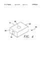
- FIG. 4is an alternative embodiment of the pointing device shown in FIG. 1.
- FIG. 1is a schematic diagram of a pointing control system 10 according to the present invention.
- System 10is a portable computer which comprises a displaying device 14 for displaying an object 18 within a three dimensional view 16 over a displaying screen 17, a computer 20 connected to the displaying device 14 with a keyboard 22 installed above it, and a pointing device 12 installed in the computer 20 for controlling rotations of the object 18 within the three dimensional view 16.
- the pointing device 12comprises a right-angled shell 24 having a horizontal plane 26 and a vertical plane 28, a first pointing controller 30 which is a track ball installed in the horizontal plane 26, a second pointing controller 32 which is also a track ball installed in the vertical plane 28, and two push buttons 34. Both the pointing controllers 30 and 32 are used for controlling rotations of the object 18.
- the three dimensional view 16comprises three mutually perpendicular axes X, Y and Z.
- the vertical plane formed by the screen 17can be represented as X-Z plane.
- the Y axisis perpendicular to the screen 17.
- the first pointing controller 30 installed in the horizontal plane 26is used for controlling rotations of the object 18 along X axis and Y axis whereas the second pointing controller 32 installed in vertical plane 28 is used for controlling rotations of the object 18 along X axis and Z axis.
- the three dimensional view 16 presented over the screen 17is substantially matched with the three dimensional arrangement of the horizontal plane 26 and the vertical plane 28 of the pointing device 12.
- a usercan thus intuitively use the first pointing controller 30 on the horizontal plane 26 to manipulate rotations of the object 18 in X axis and Y axis, and use the second pointing controller 32 on the vertical plane 28 to manipulate rotations of the object 18 in X axis and Z axis.
- FIG. 2is a schematic diagram of the structure of the first pointing controller 30 shown in FIG. 1.
- the pointing controller 30is a traditional track ball which comprises a ball 40 rotatably installed in the housing 24, two mutually perpendicular rods 42 and 44 rotatably installed in the housing 24 and attached to the ball 40 for interacting with the ball 40 to detect rotations of ball 40 in two different directions, a first angle displacement detector 46 for detecting rotations of the rod 42 and generating a corresponding first angle displacement signal, and a second angle displacement detector 48 for detecting rotations of the rod 44 and generating a corresponding second angle displacement signal.
- Each of the angle displacement detectors 46 and 48comprises a wheel 50 installed at one end of the corresponding rod and a sensing device 52 for sensing rotations of the corresponding wheel 50 to generate the first or second angle displacement signal.
- both rods 42 and 44When the ball 40 is rotated by a user, both rods 42 and 44 will be driven and make the wheels 50 of the first and second angle displacement detectors 46 and 48 rotate.
- the sensing devices 52 of both angle displacement detectors 46 and 48will then sense the rotations of the two wheels 50 and generate corresponding first and second angle displacement signals.
- the first angle displacement signal generated by the first angle displacement detector 46is used for controlling rotations of the object 18 along Y axis and the second angle displacement signal generated by the second angle displacement detector 48 is used for controlling rotations of the object 18 along X axis.
- the structure of the second pointing controller 32 shown in FIG. 1is also the same as that of the first pointing controller 30 shown in FIG. 2. It also compresses a ball rotatably installed in the vertical plane 28 of the housing 24, two mutually perpendicular rods rotatably installed in the housing 24 for interacting with the ball to detect rotations of the ball and two angle displacement detectors for detecting rotations of the two rods and generating two corresponding angle displacement signals to control rotations of the object 18 along Z axis and X axis.
- FIG. 3is function block diagram of the pointing control system 10 shown in FIG. 1.
- System 10comprises a pointing device 12, a displaying device 14 and a computer 20 electrically connected between the pointing device 12 and displaying device 14.
- the computer 20comprises a RAM (random access memory) 84 for storing programs, a central processing unit 80 for executing programs stored in the memory 84, a display control program 86 stored in the memory 84 for controlling displays of the three dimensional view 16 over the displaying device 14 and rotations of the object 18 within the three dimensional view 16 according to angle displacement signals generated by the pointing device 12, and a video circuit 82 for processing video signals displayed over the displaying device 14.
- RAMrandom access memory
- the pointing device 12comprises a first pointing controller 30 which is a track ball for generating two angle displacement signals to control rotations of the object 18 within the three dimensional view 16 along X axis and Y axis, a second pointing controller 32 which is also a track ball for generating two angle displacement signals to control rotations of the object 18 within the three dimensional view 16 along X axis and Z axis, a keypad circuit 74 composed of the two push buttons 34 for generating key signals, and a control circuit 70 for transmitting the signals generated by the pointing device 12 to the computer 20 through an interface circuit 72.
- a first pointing controller 30which is a track ball for generating two angle displacement signals to control rotations of the object 18 within the three dimensional view 16 along X axis and Y axis
- a second pointing controller 32which is also a track ball for generating two angle displacement signals to control rotations of the object 18 within the three dimensional view 16 along X axis and Z axis
- the display control program 86 of the computer 20After receiving the angle displacement signals transmitted from the interface circuit 72, the display control program 86 of the computer 20 will transform each angle displacement signal into a rotation angle according to a predetermined conversion method and then rotate the object 18 displayed in the three dimensional view 16 along a corresponding axis of the angle displacement signal.
- the program 86will receive two angle displacement signals for rotating the object 18 along the X axis because each of the two pointing controllers 30 and 32 can generate an angle displacement signal to control rotations of the object 18 along the X axis. This will make the rotation speed of the object 18 along the X axis faster than the other two axes.
- the display control program 86can select the larger angle displacement signal and neglects the smaller one, or it can average the two signals first and then rotate the object 18 according to the averaged signal.
- FIG. 4shows another pointing device 90 which is an alternative embodiment of the pointing device 12 shown in FIG. 1.
- the pointing device 90comprises a housing 91 having a horizontal plane 92 and a vertical plane 94, a first pointing controller 96 which is a track ball installed in the horizontal plane 92, a second pointing controller 98 which is a rotatable wheel installed in the vertical plane 94 which can be rotated back and forth.
- the first pointing controller 96is used for controlling rotations of the object 18 along X axis and Y axis
- the second pointing controller 98is used for controlling rotations of the object 18 along Z axis.
- the second pointing controller 98 of the pointing device 90only control rotations of the object 18 along one axis instead of two.
- the function block diagram of the pointing device 90is basically the same as that of the pointing controller 12 shown in FIG. 3.
Landscapes
- Engineering & Computer Science (AREA)
- General Engineering & Computer Science (AREA)
- Theoretical Computer Science (AREA)
- Human Computer Interaction (AREA)
- Physics & Mathematics (AREA)
- General Physics & Mathematics (AREA)
- Position Input By Displaying (AREA)
- Ultra Sonic Daignosis Equipment (AREA)
Abstract
Description
Claims (8)
Priority Applications (2)
| Application Number | Priority Date | Filing Date | Title |
|---|---|---|---|
| US08/940,836US5959614A (en) | 1997-09-30 | 1997-09-30 | Pointing control system for controlling rotations of an object within a three dimensional view |
| DE29718327UDE29718327U1 (en) | 1997-09-30 | 1997-10-15 | Pointer control for controlling rotations of an object within a three-dimensional representation |
Applications Claiming Priority (2)
| Application Number | Priority Date | Filing Date | Title |
|---|---|---|---|
| US08/940,836US5959614A (en) | 1997-09-30 | 1997-09-30 | Pointing control system for controlling rotations of an object within a three dimensional view |
| DE29718327UDE29718327U1 (en) | 1997-09-30 | 1997-10-15 | Pointer control for controlling rotations of an object within a three-dimensional representation |
Publications (1)
| Publication Number | Publication Date |
|---|---|
| US5959614Atrue US5959614A (en) | 1999-09-28 |
Family
ID=26060810
Family Applications (1)
| Application Number | Title | Priority Date | Filing Date |
|---|---|---|---|
| US08/940,836Expired - LifetimeUS5959614A (en) | 1997-09-30 | 1997-09-30 | Pointing control system for controlling rotations of an object within a three dimensional view |
Country Status (2)
| Country | Link |
|---|---|
| US (1) | US5959614A (en) |
| DE (1) | DE29718327U1 (en) |
Cited By (15)
| Publication number | Priority date | Publication date | Assignee | Title |
|---|---|---|---|---|
| US20030025673A1 (en)* | 2001-04-30 | 2003-02-06 | Microsoft Corporation | Input device including a wheel assembly for scrolling an image in multiple directions |
| US20030142144A1 (en)* | 2002-01-25 | 2003-07-31 | Silicon Graphics, Inc. | Techniques for pointing to locations within a volumetric display |
| US6618037B2 (en)* | 2000-06-23 | 2003-09-09 | Fuji Xerox Co., Ltd. | Pointing device and information processing apparatus |
| US20040001111A1 (en)* | 2002-06-28 | 2004-01-01 | Silicon Graphics, Inc. | Widgets displayed and operable on a surface of a volumetric display enclosure |
| US20040001112A1 (en)* | 2002-01-25 | 2004-01-01 | Silicon Graphics, Inc. | Volume management system for volumetric displays |
| US20040001075A1 (en)* | 2002-06-28 | 2004-01-01 | Silicon Graphics, Inc. | System for physical rotation of volumetric display enclosures to facilitate viewing |
| US6677927B1 (en)* | 1999-08-23 | 2004-01-13 | Microsoft Corporation | X-Y navigation input device |
| US20040174336A1 (en)* | 2003-03-07 | 2004-09-09 | Microsoft Corporation | Scroll wheel assembly for scrolling an image in multiple directions |
| US20040239629A1 (en)* | 2002-06-03 | 2004-12-02 | Microsoft Corporation | Modular scroll wheel with integral detent-engaging spring tab |
| US6865718B2 (en)* | 1999-09-29 | 2005-03-08 | Microsoft Corp. | Accelerated scrolling |
| US20050140655A1 (en)* | 2001-04-30 | 2005-06-30 | Microsoft Corporation | Keyboard with improved lateral region |
| US20050259077A1 (en)* | 2002-06-28 | 2005-11-24 | Adams Aditha M | Input device including a scroll wheel assembly for manipulating an image in multiple directions |
| US20060044272A1 (en)* | 2004-08-27 | 2006-03-02 | Microsoft Corporation | Scroll wheel carriage |
| US20090081973A1 (en)* | 2007-09-26 | 2009-03-26 | Analog Devices, Inc. | Multi-slot power control for wireless transmission |
| US20150213651A1 (en)* | 2013-10-10 | 2015-07-30 | Aaron SELVERSTON | Outdoor, interactive 3d viewing apparatus |
Citations (7)
| Publication number | Priority date | Publication date | Assignee | Title |
|---|---|---|---|---|
| US5019809A (en)* | 1988-07-29 | 1991-05-28 | University Of Toronto Innovations Foundation | Two-dimensional emulation of three-dimensional trackball |
| US5095303A (en)* | 1990-03-27 | 1992-03-10 | Apple Computer, Inc. | Six degree of freedom graphic object controller |
| US5311209A (en)* | 1993-03-24 | 1994-05-10 | Sysgration Ltd. | Assembled photomechanical mouse structure |
| US5477237A (en)* | 1993-06-24 | 1995-12-19 | Dell Usa, L.P. | Positioning device reporting X, Y and yaw motion |
| US5563631A (en)* | 1993-10-26 | 1996-10-08 | Canon Kabushiki Kaisha | Portable information apparatus |
| US5565891A (en)* | 1992-03-05 | 1996-10-15 | Armstrong; Brad A. | Six degrees of freedom graphics controller |
| US5619231A (en)* | 1993-04-28 | 1997-04-08 | Fujitsu Limited | Multi-dimensional coordinate input apparatus adapted for simple input operation, and system using the same |
- 1997
- 1997-09-30USUS08/940,836patent/US5959614A/ennot_activeExpired - Lifetime
- 1997-10-15DEDE29718327Upatent/DE29718327U1/ennot_activeExpired - Lifetime
Patent Citations (7)
| Publication number | Priority date | Publication date | Assignee | Title |
|---|---|---|---|---|
| US5019809A (en)* | 1988-07-29 | 1991-05-28 | University Of Toronto Innovations Foundation | Two-dimensional emulation of three-dimensional trackball |
| US5095303A (en)* | 1990-03-27 | 1992-03-10 | Apple Computer, Inc. | Six degree of freedom graphic object controller |
| US5565891A (en)* | 1992-03-05 | 1996-10-15 | Armstrong; Brad A. | Six degrees of freedom graphics controller |
| US5311209A (en)* | 1993-03-24 | 1994-05-10 | Sysgration Ltd. | Assembled photomechanical mouse structure |
| US5619231A (en)* | 1993-04-28 | 1997-04-08 | Fujitsu Limited | Multi-dimensional coordinate input apparatus adapted for simple input operation, and system using the same |
| US5477237A (en)* | 1993-06-24 | 1995-12-19 | Dell Usa, L.P. | Positioning device reporting X, Y and yaw motion |
| US5563631A (en)* | 1993-10-26 | 1996-10-08 | Canon Kabushiki Kaisha | Portable information apparatus |
Cited By (50)
| Publication number | Priority date | Publication date | Assignee | Title |
|---|---|---|---|---|
| US6677927B1 (en)* | 1999-08-23 | 2004-01-13 | Microsoft Corporation | X-Y navigation input device |
| US7665034B2 (en) | 1999-09-29 | 2010-02-16 | Microsoft Corporation | Accelerated scrolling |
| US7170491B2 (en) | 1999-09-29 | 2007-01-30 | Microsoft Corporation | Accelerated scrolling |
| US7661072B2 (en) | 1999-09-29 | 2010-02-09 | Microsoft Corporation | Accelerated scrolling |
| US20050097468A1 (en)* | 1999-09-29 | 2005-05-05 | Microsoft Corporation | Accelerated scrolling |
| US6865718B2 (en)* | 1999-09-29 | 2005-03-08 | Microsoft Corp. | Accelerated scrolling |
| US6618037B2 (en)* | 2000-06-23 | 2003-09-09 | Fuji Xerox Co., Ltd. | Pointing device and information processing apparatus |
| US20090189861A1 (en)* | 2001-04-30 | 2009-07-30 | Microsoft Corporation | Input device including a wheel assembly for scrolling an image in multiple directions |
| US7229227B2 (en)* | 2001-04-30 | 2007-06-12 | Microsoft Corporation | Keyboard with improved lateral region |
| US20040150623A1 (en)* | 2001-04-30 | 2004-08-05 | Microsoft Corporation | Input device including a wheel assembly for scrolling an image in multiple directions |
| US7199785B2 (en) | 2001-04-30 | 2007-04-03 | Microsoft Corporation | Input device including a wheel assembly for scrolling an image in multiple directions |
| US7205977B2 (en) | 2001-04-30 | 2007-04-17 | Microsoft Corporation | Input device including a wheel assembly for scrolling an image in multiple directions |
| US7079110B2 (en) | 2001-04-30 | 2006-07-18 | Microsoft Corporation | Input device including a wheel assembly for scrolling an image in multiple directions |
| US20050140655A1 (en)* | 2001-04-30 | 2005-06-30 | Microsoft Corporation | Keyboard with improved lateral region |
| US7187358B2 (en) | 2001-04-30 | 2007-03-06 | Microsoft Corporation | Input device including a wheel assembly for scrolling an image in multiple directions |
| US20050179660A1 (en)* | 2001-04-30 | 2005-08-18 | Microsoft Corp. | Input device including a wheel assembly for scrolling an image in multiple directions |
| US20030025673A1 (en)* | 2001-04-30 | 2003-02-06 | Microsoft Corporation | Input device including a wheel assembly for scrolling an image in multiple directions |
| US7463239B2 (en) | 2001-04-30 | 2008-12-09 | Microsoft Corporation | Input device including a wheel assembly for scrolling an image in multiple directions |
| US20060007153A1 (en)* | 2001-04-30 | 2006-01-12 | Microsoft Corp. | Input device including a wheel assembly for scrolling an image in multiple directions |
| US20050275628A1 (en)* | 2002-01-25 | 2005-12-15 | Alias Systems Corp. | System for physical rotation of volumetric display enclosures to facilitate viewing |
| US7528823B2 (en) | 2002-01-25 | 2009-05-05 | Autodesk, Inc. | Techniques for pointing to locations within a volumetric display |
| US20080036738A1 (en)* | 2002-01-25 | 2008-02-14 | Ravin Balakrishnan | Techniques for pointing to locations within a volumetric display |
| US7324085B2 (en)* | 2002-01-25 | 2008-01-29 | Autodesk, Inc. | Techniques for pointing to locations within a volumetric display |
| US7701441B2 (en) | 2002-01-25 | 2010-04-20 | Autodesk, Inc. | Techniques for pointing to locations within a volumetric display |
| US7839400B2 (en) | 2002-01-25 | 2010-11-23 | Autodesk, Inc. | Volume management system for volumetric displays |
| US20040001112A1 (en)* | 2002-01-25 | 2004-01-01 | Silicon Graphics, Inc. | Volume management system for volumetric displays |
| US7724251B2 (en) | 2002-01-25 | 2010-05-25 | Autodesk, Inc. | System for physical rotation of volumetric display enclosures to facilitate viewing |
| US20030142144A1 (en)* | 2002-01-25 | 2003-07-31 | Silicon Graphics, Inc. | Techniques for pointing to locations within a volumetric display |
| US7362308B2 (en) | 2002-06-03 | 2008-04-22 | Microsoft Corporation | Modular scroll wheel with integral detent-engaging spring tab |
| US7324090B2 (en) | 2002-06-03 | 2008-01-29 | Microsoft Corporation | Modular scroll wheel with integral detent-engaging sprint tab |
| US20040239629A1 (en)* | 2002-06-03 | 2004-12-02 | Microsoft Corporation | Modular scroll wheel with integral detent-engaging spring tab |
| US20050110759A1 (en)* | 2002-06-03 | 2005-05-26 | Microsoft Corporation | Modular scroll wheel with integral detent-engaging sprint tab |
| US20050259077A1 (en)* | 2002-06-28 | 2005-11-24 | Adams Aditha M | Input device including a scroll wheel assembly for manipulating an image in multiple directions |
| US20060192759A1 (en)* | 2002-06-28 | 2006-08-31 | Microsoft Corporation | Input Device Including a Scroll Wheel Assembly for Manipulating an Image in Multiple Directions |
| US7042441B2 (en)* | 2002-06-28 | 2006-05-09 | Microsoft Corporation | Input device including a scroll wheel assembly for manipulating an image in multiple directions |
| US7986318B2 (en) | 2002-06-28 | 2011-07-26 | Autodesk, Inc. | Volume management system for volumetric displays |
| US20040001111A1 (en)* | 2002-06-28 | 2004-01-01 | Silicon Graphics, Inc. | Widgets displayed and operable on a surface of a volumetric display enclosure |
| US20060125822A1 (en)* | 2002-06-28 | 2006-06-15 | Alias Systems Corp. | Volume management system for volumetric displays |
| US20040001075A1 (en)* | 2002-06-28 | 2004-01-01 | Silicon Graphics, Inc. | System for physical rotation of volumetric display enclosures to facilitate viewing |
| US7138997B2 (en) | 2002-06-28 | 2006-11-21 | Autodesk, Inc. | System for physical rotation of volumetric display enclosures to facilitate viewing |
| US7554541B2 (en) | 2002-06-28 | 2009-06-30 | Autodesk, Inc. | Widgets displayed and operable on a surface of a volumetric display enclosure |
| US20050270271A1 (en)* | 2003-03-07 | 2005-12-08 | Microsoft Corporation | Scroll wheel assembly for scrolling an image in multiple directions |
| US7075516B2 (en) | 2003-03-07 | 2006-07-11 | Microsoft Corporation | Scroll wheel assembly for scrolling an image in multiple directions |
| US20050179661A1 (en)* | 2003-03-07 | 2005-08-18 | Microsoft Corporation | Scroll wheel assembly for scrolling an image in multiple directions |
| US20040174336A1 (en)* | 2003-03-07 | 2004-09-09 | Microsoft Corporation | Scroll wheel assembly for scrolling an image in multiple directions |
| US9600098B2 (en) | 2003-03-07 | 2017-03-21 | Microsoft Technology Licensing, Llc | Scroll wheel assembly for scrolling an image in multiple directions |
| US7443382B2 (en) | 2004-08-27 | 2008-10-28 | Microsoft Corporation | Scroll wheel carriage |
| US20060044272A1 (en)* | 2004-08-27 | 2006-03-02 | Microsoft Corporation | Scroll wheel carriage |
| US20090081973A1 (en)* | 2007-09-26 | 2009-03-26 | Analog Devices, Inc. | Multi-slot power control for wireless transmission |
| US20150213651A1 (en)* | 2013-10-10 | 2015-07-30 | Aaron SELVERSTON | Outdoor, interactive 3d viewing apparatus |
Also Published As
| Publication number | Publication date |
|---|---|
| DE29718327U1 (en) | 1997-12-11 |
Similar Documents
| Publication | Publication Date | Title |
|---|---|---|
| US5959614A (en) | Pointing control system for controlling rotations of an object within a three dimensional view | |
| US6351257B1 (en) | Pointing device which uses an image picture to generate pointing signals | |
| CN104219560B (en) | The user interface of set-top box | |
| US7330198B2 (en) | Three-dimensional object manipulating apparatus, method and computer program | |
| RU2242043C2 (en) | Method for operation of user interface of portable data processing device | |
| CA2011517C (en) | Flat touch screen workpad for a data processing system | |
| CN102105853B (en) | Touch Interaction with Curved Displays | |
| EP2584446B1 (en) | Gui applications for use with 3d remote controller | |
| US7038664B2 (en) | Input device for scrolling a computer display | |
| US20040239702A1 (en) | Motion-based electronic device control apparatus and method | |
| US8102372B2 (en) | Optical mouse testing device | |
| US20140118247A1 (en) | Control apparatus, control method, program, input signal receiving apparatus, operation input apparatus, and input system | |
| US20110157231A1 (en) | Electronic control apparatus and method for responsively controlling media content displayed on portable electronic device | |
| US20130342455A1 (en) | Display apparatus, remote controlling apparatus and control method thereof | |
| US20100201618A1 (en) | User interface | |
| JP2001043017A (en) | Pointing device using two linear sensors and fingerprint for generating displacement signal | |
| CN1227014A (en) | Selective call radio with contraposed touchpad | |
| CN112817453A (en) | Virtual reality equipment and sight following method of object in virtual reality scene | |
| CN104346076B (en) | Information processing equipment, information processing method and program | |
| CN101393027A (en) | Handheld starry sky display equipment and starry sky display method | |
| JP5882517B1 (en) | Content viewing system using head-mounted display | |
| JP3277428B2 (en) | Control system | |
| JP2016225967A (en) | Content viewing system using head-mounted display | |
| US8970491B2 (en) | Computer system, computer system control method, program, and information storage medium | |
| CN213338681U (en) | Multimedia interaction device with metal touch sensor combined with real object |
Legal Events
| Date | Code | Title | Description |
|---|---|---|---|
| AS | Assignment | Owner name:PRIMAX ELECTRONICS LTD., TAIWAN Free format text:ASSIGNMENT OF ASSIGNORS INTEREST;ASSIGNOR:HO, HENG-CHUN;REEL/FRAME:008836/0481 Effective date:19970908 | |
| STCF | Information on status: patent grant | Free format text:PATENTED CASE | |
| FPAY | Fee payment | Year of fee payment:4 | |
| AS | Assignment | Owner name:TRANSPACIFIC PLASMA, LLC,TAIWAN Free format text:ASSIGNMENT OF ASSIGNORS INTEREST;ASSIGNOR:PRIMAX ELECTRONICS LTD.;REEL/FRAME:018047/0778 Effective date:20060626 Owner name:TRANSPACIFIC PLASMA, LLC, TAIWAN Free format text:ASSIGNMENT OF ASSIGNORS INTEREST;ASSIGNOR:PRIMAX ELECTRONICS LTD.;REEL/FRAME:018047/0778 Effective date:20060626 | |
| AS | Assignment | Owner name:PRIMAX ELECTRONICS LTD.,TAIWAN Free format text:LICENSE;ASSIGNORS:TRANSPACIFIC IP LTD.;TRANSPACIFIC PLASMA LLC;REEL/FRAME:018787/0358 Effective date:20060404 Owner name:PRIMAX ELECTRONICS LTD., TAIWAN Free format text:LICENSE;ASSIGNORS:TRANSPACIFIC IP LTD.;TRANSPACIFIC PLASMA LLC;REEL/FRAME:018787/0358 Effective date:20060404 | |
| FPAY | Fee payment | Year of fee payment:8 | |
| FEPP | Fee payment procedure | Free format text:PAYOR NUMBER ASSIGNED (ORIGINAL EVENT CODE: ASPN); ENTITY STATUS OF PATENT OWNER: LARGE ENTITY Free format text:PAYER NUMBER DE-ASSIGNED (ORIGINAL EVENT CODE: RMPN); ENTITY STATUS OF PATENT OWNER: LARGE ENTITY | |
| FPAY | Fee payment | Year of fee payment:12 | |
| AS | Assignment | Owner name:GIZMODO LIMITED LIABILITY COMPANY, DELAWARE Free format text:MERGER;ASSIGNOR:TRANSPACIFIC PLASMA, LLC;REEL/FRAME:030628/0659 Effective date:20130213 | |
| AS | Assignment | Owner name:INTELLECTUAL VENTURES I LLC, DELAWARE Free format text:MERGER;ASSIGNOR:GIZMODO LIMITED LIABILITY COMPANY;REEL/FRAME:030639/0298 Effective date:20130214 | |
| AS | Assignment | Owner name:HANGER SOLUTIONS, LLC, GEORGIA Free format text:ASSIGNMENT OF ASSIGNORS INTEREST;ASSIGNOR:INTELLECTUAL VENTURES ASSETS 161 LLC;REEL/FRAME:052159/0509 Effective date:20191206 | |
| AS | Assignment | Owner name:INTELLECTUAL VENTURES ASSETS 161 LLC, DELAWARE Free format text:ASSIGNMENT OF ASSIGNORS INTEREST;ASSIGNOR:INTELLECTUAL VENTURES I LLC;REEL/FRAME:051945/0001 Effective date:20191126 |