US5959610A - Computer-mirrored panel input device - Google Patents
Computer-mirrored panel input deviceDownload PDFInfo
- Publication number
- US5959610A US5959610AUS08/371,462US37146295AUS5959610AUS 5959610 AUS5959610 AUS 5959610AUS 37146295 AUS37146295 AUS 37146295AUS 5959610 AUS5959610 AUS 5959610A
- Authority
- US
- United States
- Prior art keywords
- real
- input
- user
- display screen
- knobs
- Prior art date
- Legal status (The legal status is an assumption and is not a legal conclusion. Google has not performed a legal analysis and makes no representation as to the accuracy of the status listed.)
- Expired - Lifetime
Links
- 230000033001locomotionEffects0.000claimsdescription18
- 230000005236sound signalEffects0.000claimsdescription18
- 238000000034methodMethods0.000claimsdescription7
- 230000006870functionEffects0.000claimsdescription6
- 230000000007visual effectEffects0.000claimsdescription6
- 238000004891communicationMethods0.000claimsdescription5
- 230000008859changeEffects0.000claimsdescription2
- 230000004044responseEffects0.000claims6
- 238000004519manufacturing processMethods0.000description5
- 238000010586diagramMethods0.000description4
- 230000003750conditioning effectEffects0.000description2
- 238000003825pressingMethods0.000description2
- 230000008569processEffects0.000description2
- 230000010076replicationEffects0.000description2
- 230000002411adverseEffects0.000description1
- 230000004075alterationEffects0.000description1
- 238000003491arrayMethods0.000description1
- 230000001143conditioned effectEffects0.000description1
- 230000020169heat generationEffects0.000description1
- 230000005055memory storageEffects0.000description1
- 230000003340mental effectEffects0.000description1
- 230000003252repetitive effectEffects0.000description1
- 238000000926separation methodMethods0.000description1
Images


Classifications
- H—ELECTRICITY
- H01—ELECTRIC ELEMENTS
- H01H—ELECTRIC SWITCHES; RELAYS; SELECTORS; EMERGENCY PROTECTIVE DEVICES
- H01H19/00—Switches operated by an operating part which is rotatable about a longitudinal axis thereof and which is acted upon directly by a solid body external to the switch, e.g. by a hand
- G—PHYSICS
- G11—INFORMATION STORAGE
- G11B—INFORMATION STORAGE BASED ON RELATIVE MOVEMENT BETWEEN RECORD CARRIER AND TRANSDUCER
- G11B27/00—Editing; Indexing; Addressing; Timing or synchronising; Monitoring; Measuring tape travel
- G11B27/02—Editing, e.g. varying the order of information signals recorded on, or reproduced from, record carriers
- G11B27/031—Electronic editing of digitised analogue information signals, e.g. audio or video signals
- G11B27/034—Electronic editing of digitised analogue information signals, e.g. audio or video signals on discs
- H—ELECTRICITY
- H01—ELECTRIC ELEMENTS
- H01H—ELECTRIC SWITCHES; RELAYS; SELECTORS; EMERGENCY PROTECTIVE DEVICES
- H01H2217/00—Facilitation of operation; Human engineering
- H01H2217/032—Feedback about selected symbol, e.g. display
- Y—GENERAL TAGGING OF NEW TECHNOLOGICAL DEVELOPMENTS; GENERAL TAGGING OF CROSS-SECTIONAL TECHNOLOGIES SPANNING OVER SEVERAL SECTIONS OF THE IPC; TECHNICAL SUBJECTS COVERED BY FORMER USPC CROSS-REFERENCE ART COLLECTIONS [XRACs] AND DIGESTS
- Y10—TECHNICAL SUBJECTS COVERED BY FORMER USPC
- Y10S—TECHNICAL SUBJECTS COVERED BY FORMER USPC CROSS-REFERENCE ART COLLECTIONS [XRACs] AND DIGESTS
- Y10S715/00—Data processing: presentation processing of document, operator interface processing, and screen saver display processing
- Y10S715/978—Audio interaction as part of an operator interface
Definitions
- the present inventionis in the area of instruments and systems for managing and mixing audio input for production purposes, such as recordings, and pertains particularly to input actuators and means for resetting same.
- Audio production for television, video, film, and recorded music salesis a large and growing enterprise, and is the foundation of much of the entertainment industry.
- Automation in the form of computerizationis becoming more and more important as the basis of technical advances in this industry, to provide ability to mix and process more sophisticated and more voluminous audio input, and to provide more flexibility in output.
- Computerizationis also seen as a requirement for cost-effective competition. Manual instruments, systems, and techniques are, by comparison, increasingly more expensive to use.
- the basic instrument of audio productionis the production mixing console, a workstation presenting an interface to a sound engineer through which he or she may condition multiple channels of audio input, and mix the conditioned results into mono or stereo outputs for direct broadcast or for recording.
- a production mixing consolehereinafter a mixer, typically presents arrays of input devices, such as switches, knobs, and "faders", for an engineer to set to condition and route audio signals.
- a faderis typically a slide rheostat through which an amplitude may be adjusted as a result of the linear position of the input lever relative to a track.
- Mixerstypically route audio input signals to individual channels, and each such channel has a repetitive layout of switches, knobs, and faders.
- a single channelcan have more than one input, such as a microphone input and an input from an instrument, a group of instruments, or a tape.
- an engineercan select microphone, line, and tape inputs, route the inputs to signal conditioning devices like faders and equalizers, and mix and route the output from the conditioning devices as well.
- Audio mixingis historically a rather recent development.
- rock-and-roll musicwas first introduced there was no such device as a mixer.
- recordingwas done by direct input.
- Modern mixingwas initiated about the time of the appearance of the Beatles, and the first units were highly individualistic.
- direct audio mixerscontinued to be developed, and continued to be relatively small units with a few channels and were very unique in layout.
- standardsbegan to appear, especially relative to layout of switches, rotary potentiometers, and faders. With a standard layout it became possible for a sound engineer to go from one studio to another, and take over the functions comfortably.
- FIG. 1is an isometric view of a system 11 developed by Euphonix, Inc. of Palo Alto, Calif. for applying the power of digital techniques to audio processing and mixing.
- system console 13is almost entirely digital, and all audio processing is accomplished in an audio tower 15.
- FIG. 2is an illustration of a pattern 17 of input devices, such as knobs, slide rheostats, and so forth, on the front panel of the console of FIG. 1.
- the purpose of FIG. 2is to illustrate the density of input devices and position indicators, which pretty much cover the console surface, being arranged in channels and blocks of like devices.
- These input devicesprovide digital position signals which are manipulated and stored, and used to compose and send digital signals to digitally controllable audio processing and mixing devices in the audio tower.
- knobsoperate rotary potentiometers.
- An exampleis a one-turn pot.
- the pothad a minimum and a maximum input setting, and could be set at any position in between, the resistance of the pot being proportional to the setting position setting.
- a knobIn a digital system a knob is typically sensed by a shaft encoder, and the "real" setting is determined by recording the amount of rotary movement from an assigned base, or zero, position. Such a rotary input can correctly be called an infinite knob, in that there is no minimum or maximum physical setting. A new base position may be assigned at any time. Likewise, a new position relative to "zero" may be assigned at any time.
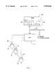
- FIG. 3is a block diagram illustrating the general situation with a series of digital input knobs 19, 21, and 23, representing a set of knobs 1-n.
- Shaft encoders 25, 27, and 29respectively "read” the rotation of knobs 19, 21, and 23, and present the magnitude and direction of rotary movement to a CPU 31, configured to calculate and store values in a series of operating registers 33 in RAM 39.
- the values in operating registers 33are used by the digital system to drive signal processors that actually alter and mix the audio signals input to the system. It will be apparent to one with skill in the art, as well, that there may be multiple processors, various kinds of bus devices such as bus 30, and other arrangements of digital elements for computation and communication, which are known in the art.
- the encodersread discrete increments of rotary motion in some number of increments of revolution, the greater the number the greater the resolution. For example, a particular encoder may be configured to report 256 increments per revolution.
- the setting for each knobis determined in operating registers 33 by adding and subtracting the discrete increments of rotation.
- a setting (snapshot) of the series of knobs 1-nis made on signal by the engineer operating the board by storing the immediate value of operating registers 33 in another series of registers 35 for later retrieval and use, and then continuing to update the immediate registers. Any number of snapshots may be made and stored, depending on the configuration of the system, in separate memory register locations, with the snapshots having names or numbers for identification in retrieval.
- One solution known to the inventorsis to have absolute indicators on the knobs and the panel, and to provide motor drives for the knobs, so when a snapshot is recalled, the recalled values are used to operate the motors to drive the knobs to the recalled setting. Then the engineer can operate the board from the new position just as is done in the older, directly-coupled systems.
- the motor drivesare relatively bulky, the drives are expensive, having to be coupled in a manner, such as by clutches, to allow manual movement of the knobs after resetting, and the density of control and power wiring behind the panel is typically more than doubled. Heat generation is increased, and system reliability is adversely affected.
- knob 37has a series of built-in LEDs, such as LED 40, around the periphery, and an absolute indicator 41 on the panel.
- LED 40the new setting value is used to light the one appropriate LED in the knob that most closely shows the new setting relative to absolute indicator 41. If the recalled value for this particular knob indicates 50% of full value, for example, the system will light LED 43, 180 degrees from the absolute indicator.
- the knobis then effectively "reset” just as though driven to a new position by a motor. The engineer knows which direction of rotation increases setting value, so that is not a problem.
- the LEDs in the knob solutionsuffers from the density problem as well.
- the panel densitydictates that knobs are relatively small, and there is a low limit to the number of LEDs that may be installed in one knob, providing poor resolution. Also, there is the problem of selectively lighting the LEDs in the rotary knob.
- FIG. 4Bshows a variation of the solution of FIG. 4A.
- knob 45has an absolute indicator 47, and the LEDs are arranged in a circle around the knob, such as LED 49.
- the appropriate LEDis lighted indicating the setting. For example, if the recalled setting is 50% of full value, LED 51 may be lighted.
- FIG. 4Brelieves the resolution problem of that of FIG. 4A, but not by much.
- a system for digital input and virtual feedbackcomprising manually operable input means for providing a digital signal relative to movement of the input means, display means for displaying a virtual image of the manually operable input means including position indication, CPU means for managing operation of the system, and for receiving, processing, and routing digital signals from the input means and driving the display means, and memory means for storing data and control routines for use by said CPU means.
- the CPU meansis configured to drive the display means to provide visual position indication on the virtual image corresponding to movement of the input means, and to provide the digital signals to digitally controllable devices.
- the inventionis particularly applicable to a digital audio mixer panel, and in that aspect allows resetting of inputs for various control devices without requiring manual resetting of the input devices.
- input meansis provided to selectively reassign one set of physical input devices, such a rotary knobs, to various different controlled devices.
- the presentation of the input devices as virtual images with position indicatorsallows the real input panel to remain free of resettable position indicators, and input device position to be reliably indicated with excellent resolution.
- FIG. 1is an isometric view of a digital audio mixing console in the prior art.
- FIG. 2is a partial view of input operating devices on the console of FIG. 1.
- FIG. 3is a block diagram illustrating knob input operations in a digital console system.
- FIG. 4Ashows one possible solution to the problem of knob position in snapshot recall.
- FIG. 4Bshows a variation to the solution of FIG. 4A.
- FIG. 5Ais an isometric view of an input panel with a display according to an embodiment of the invention.
- FIG. 5Bis a block diagram of the input panel of FIG. 5A.
- FIG. 5Ashows an array of rotary knobs 53 adjacent a flat panel display 55 in a system 57 according to an embodiment of the present invention for providing digital signals to control audio mixing and processing equipment.
- the audio mixing and processing elementsare not shown, and may be in a separate enclosure at some distance, and addressed by digital communication lines, such as a serial communication link.
- the displayneed not be a flat panel display, but such a display lends itself most conveniently to embodiments of the invention.
- knobs 59are arranged in a rectangular array 4 wide and three deep, for a total of 12 physical knobs.
- FIG. 5Bis a block diagram showing the general electronic arrangement of elements in system 57.
- Knobs 59feed rotary information to CPU 61 which communicates on a bus 63 to RAM 65 to maintain position setting values for knobs 59 in operating registers 67. Snapshots signalled cause position settings in registers 67 to be stored in separate registers, such as registers 69, identified for later retrieval.
- the operating registersare used in the system to drive digitally responsive processing and mixing devices to accomplish the purposes of the audio engineer, which devices may, as described above, be located in a separate enclosure.
- the values of the operating registersare used in conjunction with stored control routines and data to drive display panel 55 to display an array 71 of virtual rotary knobs corresponding on a one-to-one positional basis to physical rotary knob array 53.
- the operatormanipulates physical knobs such as knob 59 in array 53, and the computerized system displays virtual corresponding knobs in array 71.
- the physical knobsneed not have, and in this embodiment, do not have, indicators, either on the knobs or on the panel. Absolute indicators are indicated on both the virtual panel and knobs in the display.
- the real time correspondence of the real and virtual knobsis such that as an operator manipulates (rotates) a real knob, such as upper left knob 59 (FIG. 5A), the geometrically corresponding knob 73 in the display is seen to rotate by a like amount, with a knob position indicator 75 changing position in apparently real time.
- a real knobsuch as upper left knob 59 (FIG. 5A)
- the geometrically corresponding knob 73 in the displayis seen to rotate by a like amount, with a knob position indicator 75 changing position in apparently real time.
- the virtual knobsare, in this embodiment, implemented as a full plan view (no shadowing), it is actually only necessary to move the knob position indicators to indicate knob rotation.
- the real and virtual knobsare color coded to increase the comfort of visual correlation for the operator engineer.
- the codingcan be by any of a number of schemes, with the virtual knob carrying the same color as the real.
- knob size, shape, and other visual indicatorsmight be used as well.
- the inventionis applicable as well to other than knobs, although all the advantages of the replication of knob inputs are not realized.
- an array of pushbuttonsmay be replicated, or pushbuttons along with knobs or other input devices, with the state of the pushbutton switches indicated in the virtual array. This allows for use of real pushbuttons without internal LEDs to indicate state, and for snapshots to be retrieved for pushbutton states as well as knob positions.
- Slide rheostatsmay also be replicated, but this implementation suffers from the drawback that the actual physical faders will be in a different position than the virtual after retrieval of a snapshot. In this case the operator has to move the physical faders to the retrieved indicated position, and the equivalence may be signalled with visual, auditory, or even sensual indication.
- the virtual replication of input indicatorshas another dimension beyond solving the feedback problem for snapshot retrieval. That is that the correspondence of input devices to audio processing and mixing equipment may be selectable.
- an audio mixing consoleas shown in FIG. 1, there are typically multiple channels assigned by such as patch cords to individual or grouped audio inputs.
- lead guitarmay be assigned to Channel 1, base to Channel 2, keyboard to channel 3, etc.
- Each of the channelstypically has a similar array of input devices assigned to particular processing devices.
- a single channelmay have a one or more bar graph meters assignable to various sources, an input amplifier controlled by certain input devices, filters, one or more faders, and other associated processing and mixing equipment.
- the one set of physical input devicesmay be assigned selectively to different channels by pressing one of attention keys 79, and to a function within a channel by pressing one of attention keys 81.
- the displaychanges to show the "current" setting for the particular function in the particular channel selected, and a caption or other legend, such as caption 83, changes to indicate the channel and function selected. In this case the selection of Channel 5 EQ (for equalizer) is shown.
- an entire sophisticated mixer consolemay be implemented by a single array of input devices, and a single display, while still retaining all of the necessary feedback ability and the physical feel of manual manipulation for "playing" the board.
Landscapes
- Circuit For Audible Band Transducer (AREA)
Abstract
Description
Claims (28)
Priority Applications (2)
| Application Number | Priority Date | Filing Date | Title |
|---|---|---|---|
| US08/371,462US5959610A (en) | 1993-06-21 | 1995-01-11 | Computer-mirrored panel input device |
| US08/912,384US6057829A (en) | 1993-06-21 | 1997-08-18 | Computer-mirrored panel input device |
Applications Claiming Priority (2)
| Application Number | Priority Date | Filing Date | Title |
|---|---|---|---|
| US8029693A | 1993-06-21 | 1993-06-21 | |
| US08/371,462US5959610A (en) | 1993-06-21 | 1995-01-11 | Computer-mirrored panel input device |
Related Parent Applications (1)
| Application Number | Title | Priority Date | Filing Date |
|---|---|---|---|
| US8029693AContinuation | 1993-06-21 | 1993-06-21 |
Related Child Applications (1)
| Application Number | Title | Priority Date | Filing Date |
|---|---|---|---|
| US08/912,384ContinuationUS6057829A (en) | 1993-06-21 | 1997-08-18 | Computer-mirrored panel input device |
Publications (1)
| Publication Number | Publication Date |
|---|---|
| US5959610Atrue US5959610A (en) | 1999-09-28 |
Family
ID=22156483
Family Applications (2)
| Application Number | Title | Priority Date | Filing Date |
|---|---|---|---|
| US08/371,462Expired - LifetimeUS5959610A (en) | 1993-06-21 | 1995-01-11 | Computer-mirrored panel input device |
| US08/912,384Expired - LifetimeUS6057829A (en) | 1993-06-21 | 1997-08-18 | Computer-mirrored panel input device |
Family Applications After (1)
| Application Number | Title | Priority Date | Filing Date |
|---|---|---|---|
| US08/912,384Expired - LifetimeUS6057829A (en) | 1993-06-21 | 1997-08-18 | Computer-mirrored panel input device |
Country Status (1)
| Country | Link |
|---|---|
| US (2) | US5959610A (en) |
Cited By (57)
| Publication number | Priority date | Publication date | Assignee | Title |
|---|---|---|---|---|
| GB2354140A (en)* | 1999-09-09 | 2001-03-14 | Sony Uk Ltd | Display and control panel e.g. for audio mixers |
| US6356045B1 (en) | 2000-07-17 | 2002-03-12 | Otari Inc. | Operating knob device and electronic equipment including the same |
| US20020080981A1 (en)* | 2000-12-22 | 2002-06-27 | Yamaha Corporation | Signal processing method, program, and signal processing apparatus |
| US20020107592A1 (en)* | 2001-02-06 | 2002-08-08 | Craig David Iain | Panel search engine for digital sound processing systems |
| US20040066943A1 (en)* | 2002-10-04 | 2004-04-08 | Yamaha Corporation | Mixing console having visual marking system applied to manual operators with subgrouping |
| US6728382B1 (en)* | 1998-02-23 | 2004-04-27 | Euphonix, Inc. | Functional panel for audio mixer |
| US20040179695A1 (en)* | 2003-03-10 | 2004-09-16 | Yamaha Corporation | Audio signal processing device |
| USD500493S1 (en)* | 2004-01-08 | 2005-01-04 | American Dj Supply, Inc. | Audio mixer |
| US20050090913A1 (en)* | 2003-10-28 | 2005-04-28 | Yamaha Corporation | Parameter display method and program therefor, and parameter setting apparatus |
| US20050212802A1 (en)* | 2004-03-09 | 2005-09-29 | Yamaha Corporation | Apparatus for displaying formation of network |
| US20050212781A1 (en)* | 2004-03-25 | 2005-09-29 | Clapper Edward O | Performance control apparatus |
| US20060030957A1 (en)* | 2004-08-03 | 2006-02-09 | Yamaha Corporation | Method, apparatus and program for setting function to operation control of signal processing apparatus |
| US20060060071A1 (en)* | 2004-09-21 | 2006-03-23 | Yamaha Corporation | Parameter setting apparatus and method |
| US20060195801A1 (en)* | 2005-02-28 | 2006-08-31 | Ryuichi Iwamura | User interface with thin display device |
| US7187357B1 (en)* | 1998-10-26 | 2007-03-06 | Studer Professional Audio Ag | Device for entering values using a display screen |
| US20070156290A1 (en)* | 2002-11-15 | 2007-07-05 | Yigal Froman | Virtual Dial Irrigation Controller |
| US20070170168A1 (en)* | 2007-04-13 | 2007-07-26 | Moschetti Mitchell R | Color-coded cooktop and controls |
| USD553608S1 (en) | 2006-03-28 | 2007-10-23 | Numark Industries Llc | Docking system and mixer for portable media devices |
| USD553641S1 (en) | 2006-03-28 | 2007-10-23 | Numark Industries Llc | Media storage manager and player |
| US20070280489A1 (en)* | 2006-03-28 | 2007-12-06 | Numark Industries, Llc | Docking system and mixer for portable media devices with graphical interface |
| USD560203S1 (en) | 2006-03-28 | 2008-01-22 | Numark Industries, Llc | Combined media player and computer controller |
| US20080056514A1 (en)* | 2006-07-05 | 2008-03-06 | Yamaha Corporation | Audio signal processing system |
| US20100313409A1 (en)* | 2006-09-11 | 2010-12-16 | Apple Inc. | Hybrid button |
| US20110013786A1 (en)* | 2009-06-19 | 2011-01-20 | PreSonus Audio Electronics Inc. | Multichannel mixer having multipurpose controls and meters |
| US7910843B2 (en) | 2007-09-04 | 2011-03-22 | Apple Inc. | Compact input device |
| US7932897B2 (en) | 2004-08-16 | 2011-04-26 | Apple Inc. | Method of increasing the spatial resolution of touch sensitive devices |
| US8022935B2 (en) | 2006-07-06 | 2011-09-20 | Apple Inc. | Capacitance sensing electrode with integrated I/O mechanism |
| US8059099B2 (en) | 2006-06-02 | 2011-11-15 | Apple Inc. | Techniques for interactive input to portable electronic devices |
| USD654345S1 (en)* | 2011-06-09 | 2012-02-21 | Alto Professional, Llc | Knob |
| US8125461B2 (en) | 2008-01-11 | 2012-02-28 | Apple Inc. | Dynamic input graphic display |
| US8274479B2 (en) | 2006-10-11 | 2012-09-25 | Apple Inc. | Gimballed scroll wheel |
| US8395590B2 (en) | 2008-12-17 | 2013-03-12 | Apple Inc. | Integrated contact switch and touch sensor elements |
| US8416198B2 (en) | 2007-12-03 | 2013-04-09 | Apple Inc. | Multi-dimensional scroll wheel |
| US8446370B2 (en) | 2002-02-25 | 2013-05-21 | Apple Inc. | Touch pad for handheld device |
| US8482530B2 (en) | 2006-11-13 | 2013-07-09 | Apple Inc. | Method of capacitively sensing finger position |
| US8514185B2 (en) | 2006-07-06 | 2013-08-20 | Apple Inc. | Mutual capacitance touch sensing device |
| US8537132B2 (en) | 2005-12-30 | 2013-09-17 | Apple Inc. | Illuminated touchpad |
| US8552990B2 (en) | 2003-11-25 | 2013-10-08 | Apple Inc. | Touch pad for handheld device |
| US8683378B2 (en) | 2007-09-04 | 2014-03-25 | Apple Inc. | Scrolling techniques for user interfaces |
| US8743060B2 (en) | 2006-07-06 | 2014-06-03 | Apple Inc. | Mutual capacitance touch sensing device |
| US8749493B2 (en) | 2003-08-18 | 2014-06-10 | Apple Inc. | Movable touch pad with added functionality |
| US8816967B2 (en) | 2008-09-25 | 2014-08-26 | Apple Inc. | Capacitive sensor having electrodes arranged on the substrate and the flex circuit |
| US8820133B2 (en) | 2008-02-01 | 2014-09-02 | Apple Inc. | Co-extruded materials and methods |
| US20140266569A1 (en)* | 2013-03-15 | 2014-09-18 | Miselu, Inc | Controlling music variables |
| US8872771B2 (en) | 2009-07-07 | 2014-10-28 | Apple Inc. | Touch sensing device having conductive nodes |
| US20150029145A1 (en)* | 2013-07-24 | 2015-01-29 | Native Instruments Gmbh | Method, Apparatus and Computer-Readable Storage Means for Adjusting at Least Two Parameters |
| US8952886B2 (en) | 2001-10-22 | 2015-02-10 | Apple Inc. | Method and apparatus for accelerated scrolling |
| US20150193073A1 (en)* | 2012-09-21 | 2015-07-09 | Diehl Ako Stiftung & Co. Kg | Virtual touch knob assembly |
| US9192110B2 (en) | 2010-08-11 | 2015-11-24 | The Toro Company | Central irrigation control system |
| US9354751B2 (en) | 2009-05-15 | 2016-05-31 | Apple Inc. | Input device with optimized capacitive sensing |
| US9367151B2 (en) | 2005-12-30 | 2016-06-14 | Apple Inc. | Touch pad with symbols based on mode |
| US9454256B2 (en) | 2008-03-14 | 2016-09-27 | Apple Inc. | Sensor configurations of an input device that are switchable based on mode |
| USD815064S1 (en) | 2016-04-05 | 2018-04-10 | Dasz Instruments Inc. | Music control device |
| US10048667B1 (en) | 2017-07-20 | 2018-08-14 | Brandon Vinyard | Knob for an electric mixer |
| USD839240S1 (en) | 2017-07-20 | 2019-01-29 | Brandon Vinyard | Mixer knob |
| US10446129B2 (en) | 2016-04-06 | 2019-10-15 | Dariusz Bartlomiej Garncarz | Music control device and method of operating same |
| US11533033B2 (en)* | 2020-06-12 | 2022-12-20 | Bose Corporation | Audio signal amplifier gain control |
Families Citing this family (17)
| Publication number | Priority date | Publication date | Assignee | Title |
|---|---|---|---|---|
| GB9722766D0 (en) | 1997-10-28 | 1997-12-24 | British Telecomm | Portable computers |
| US6813524B2 (en)* | 2001-08-06 | 2004-11-02 | Emerson Electric Co. | Appliance control system with auxiliary inputs |
| US7046230B2 (en)* | 2001-10-22 | 2006-05-16 | Apple Computer, Inc. | Touch pad handheld device |
| US7345671B2 (en) | 2001-10-22 | 2008-03-18 | Apple Inc. | Method and apparatus for use of rotational user inputs |
| EP1434372B1 (en) | 2002-12-24 | 2014-08-27 | Yamaha Corporation | Operation panel for mixing system |
| JP4135624B2 (en)* | 2003-11-19 | 2008-08-20 | ヤマハ株式会社 | How to manage component data |
| EP1569371A3 (en)* | 2004-02-27 | 2012-10-10 | Yamaha Corporation | Editing apparatus of scene data for digital mixer |
| US7738980B2 (en)* | 2004-03-04 | 2010-06-15 | Yamaha Corporation | Apparatus for editing configuration data of digital mixer |
| JP4192841B2 (en)* | 2004-05-17 | 2008-12-10 | ヤマハ株式会社 | Mixer engine control device and program |
| US7810164B2 (en)* | 2004-11-11 | 2010-10-05 | Yamaha Corporation | User management method, and computer program having user authorization management function |
| US7671837B2 (en)* | 2005-09-06 | 2010-03-02 | Apple Inc. | Scrolling input arrangements using capacitive sensors on a flexible membrane |
| US7880729B2 (en) | 2005-10-11 | 2011-02-01 | Apple Inc. | Center button isolation ring |
| US9654104B2 (en) | 2007-07-17 | 2017-05-16 | Apple Inc. | Resistive force sensor with capacitive discrimination |
| JP5120198B2 (en)* | 2008-10-22 | 2013-01-16 | ヤマハ株式会社 | Panel opening / closing structure of electric operation device |
| US9179235B2 (en)* | 2008-11-07 | 2015-11-03 | Adobe Systems Incorporated | Meta-parameter control for digital audio data |
| JP2010171226A (en)* | 2009-01-23 | 2010-08-05 | Yamaha Corp | Housing structure of acoustic adjusting device |
| GB2511668A (en)* | 2012-04-12 | 2014-09-10 | Supercell Oy | System and method for controlling technical processes |
Citations (14)
| Publication number | Priority date | Publication date | Assignee | Title |
|---|---|---|---|---|
| US4635288A (en)* | 1983-04-22 | 1987-01-06 | Soundout Laboratories, Ltd. | Electrical signal mixing apparatus |
| US4644337A (en)* | 1984-10-29 | 1987-02-17 | Tektronix, Inc. | Method and apparatus for controlling oscilloscope displayed menu selection |
| US4918293A (en)* | 1984-12-24 | 1990-04-17 | Robertshaw Controls Company | Electrically operated appliance controls and methods of making the same |
| US4964004A (en)* | 1983-12-02 | 1990-10-16 | Lex Computer And Management Corporation | Video composition method and apparatus employing visual and tactile feedback |
| US5060272A (en)* | 1989-10-13 | 1991-10-22 | Yamahan Corporation | Audio mixing console |
| US5128661A (en)* | 1982-10-12 | 1992-07-07 | Robertshaw Controls Company | Solid state rotary entry control system |
| US5212733A (en)* | 1990-02-28 | 1993-05-18 | Voyager Sound, Inc. | Sound mixing device |
| US5239458A (en)* | 1989-07-26 | 1993-08-24 | Yamaha Corporation | Fader device having a fine adjustment of the signal level |
| US5243513A (en)* | 1991-04-23 | 1993-09-07 | Peters John M | Automation control with improved operator/system interface |
| US5257317A (en)* | 1988-09-01 | 1993-10-26 | Stavrou Michael P | Sound recording console |
| US5270689A (en)* | 1988-10-27 | 1993-12-14 | Baverische Motoren Werke Ag | Multi-function operating device |
| US5299267A (en)* | 1990-10-26 | 1994-03-29 | Sony Corporation | Operating apparatus of an audio mixer |
| US5327160A (en)* | 1991-05-09 | 1994-07-05 | Asher David J | Touch sensitive user interface for television control |
| US5485600A (en)* | 1992-11-09 | 1996-01-16 | Virtual Prototypes, Inc. | Computer modelling system and method for specifying the behavior of graphical operator interfaces |
- 1995
- 1995-01-11USUS08/371,462patent/US5959610A/ennot_activeExpired - Lifetime
- 1997
- 1997-08-18USUS08/912,384patent/US6057829A/ennot_activeExpired - Lifetime
Patent Citations (14)
| Publication number | Priority date | Publication date | Assignee | Title |
|---|---|---|---|---|
| US5128661A (en)* | 1982-10-12 | 1992-07-07 | Robertshaw Controls Company | Solid state rotary entry control system |
| US4635288A (en)* | 1983-04-22 | 1987-01-06 | Soundout Laboratories, Ltd. | Electrical signal mixing apparatus |
| US4964004A (en)* | 1983-12-02 | 1990-10-16 | Lex Computer And Management Corporation | Video composition method and apparatus employing visual and tactile feedback |
| US4644337A (en)* | 1984-10-29 | 1987-02-17 | Tektronix, Inc. | Method and apparatus for controlling oscilloscope displayed menu selection |
| US4918293A (en)* | 1984-12-24 | 1990-04-17 | Robertshaw Controls Company | Electrically operated appliance controls and methods of making the same |
| US5257317A (en)* | 1988-09-01 | 1993-10-26 | Stavrou Michael P | Sound recording console |
| US5270689A (en)* | 1988-10-27 | 1993-12-14 | Baverische Motoren Werke Ag | Multi-function operating device |
| US5239458A (en)* | 1989-07-26 | 1993-08-24 | Yamaha Corporation | Fader device having a fine adjustment of the signal level |
| US5060272A (en)* | 1989-10-13 | 1991-10-22 | Yamahan Corporation | Audio mixing console |
| US5212733A (en)* | 1990-02-28 | 1993-05-18 | Voyager Sound, Inc. | Sound mixing device |
| US5299267A (en)* | 1990-10-26 | 1994-03-29 | Sony Corporation | Operating apparatus of an audio mixer |
| US5243513A (en)* | 1991-04-23 | 1993-09-07 | Peters John M | Automation control with improved operator/system interface |
| US5327160A (en)* | 1991-05-09 | 1994-07-05 | Asher David J | Touch sensitive user interface for television control |
| US5485600A (en)* | 1992-11-09 | 1996-01-16 | Virtual Prototypes, Inc. | Computer modelling system and method for specifying the behavior of graphical operator interfaces |
Non-Patent Citations (2)
| Title |
|---|
| Fisher, Gene; "An Overview of a Graphical Multilanguage Applications Environment", IEEE, 1988 pp. 774-785. |
| Fisher, Gene; An Overview of a Graphical Multilanguage Applications Environment , IEEE, 1988 pp. 774 785.* |
Cited By (90)
| Publication number | Priority date | Publication date | Assignee | Title |
|---|---|---|---|---|
| US6728382B1 (en)* | 1998-02-23 | 2004-04-27 | Euphonix, Inc. | Functional panel for audio mixer |
| US20070159460A1 (en)* | 1998-10-26 | 2007-07-12 | Studer Professional Audio Ag | Device for entering values with a display screen |
| US7187357B1 (en)* | 1998-10-26 | 2007-03-06 | Studer Professional Audio Ag | Device for entering values using a display screen |
| GB2354140B (en)* | 1999-09-09 | 2004-03-10 | Sony Uk Ltd | Display and control panel |
| GB2354140A (en)* | 1999-09-09 | 2001-03-14 | Sony Uk Ltd | Display and control panel e.g. for audio mixers |
| US6356045B1 (en) | 2000-07-17 | 2002-03-12 | Otari Inc. | Operating knob device and electronic equipment including the same |
| US6987858B2 (en)* | 2000-12-22 | 2006-01-17 | Yamaha Corporation | Signal processing method, program, and signal processing apparatus |
| US20020080981A1 (en)* | 2000-12-22 | 2002-06-27 | Yamaha Corporation | Signal processing method, program, and signal processing apparatus |
| US20020107592A1 (en)* | 2001-02-06 | 2002-08-08 | Craig David Iain | Panel search engine for digital sound processing systems |
| US9977518B2 (en) | 2001-10-22 | 2018-05-22 | Apple Inc. | Scrolling based on rotational movement |
| US9009626B2 (en)* | 2001-10-22 | 2015-04-14 | Apple Inc. | Method and apparatus for accelerated scrolling |
| US8952886B2 (en) | 2001-10-22 | 2015-02-10 | Apple Inc. | Method and apparatus for accelerated scrolling |
| US8446370B2 (en) | 2002-02-25 | 2013-05-21 | Apple Inc. | Touch pad for handheld device |
| US10353565B2 (en) | 2002-02-25 | 2019-07-16 | Apple Inc. | Input apparatus and button arrangement for handheld device |
| US20040066943A1 (en)* | 2002-10-04 | 2004-04-08 | Yamaha Corporation | Mixing console having visual marking system applied to manual operators with subgrouping |
| US7366313B2 (en)* | 2002-10-04 | 2008-04-29 | Yamaha Corporation | Mixing console having visual marking system applied to manual operators with subgrouping |
| US7761189B2 (en)* | 2002-11-15 | 2010-07-20 | The Toro Company | Virtual dial irrigation controller |
| US20070156290A1 (en)* | 2002-11-15 | 2007-07-05 | Yigal Froman | Virtual Dial Irrigation Controller |
| US20040179695A1 (en)* | 2003-03-10 | 2004-09-16 | Yamaha Corporation | Audio signal processing device |
| US7561934B2 (en)* | 2003-03-10 | 2009-07-14 | Yamaha Corporation | Audio signal processing device |
| US8749493B2 (en) | 2003-08-18 | 2014-06-10 | Apple Inc. | Movable touch pad with added functionality |
| US20050090913A1 (en)* | 2003-10-28 | 2005-04-28 | Yamaha Corporation | Parameter display method and program therefor, and parameter setting apparatus |
| US7945060B2 (en)* | 2003-10-28 | 2011-05-17 | Yamaha Corporation | Parameter display method and program therefor, and parameter setting apparatus |
| US8933890B2 (en) | 2003-11-25 | 2015-01-13 | Apple Inc. | Techniques for interactive input to portable electronic devices |
| US8552990B2 (en) | 2003-11-25 | 2013-10-08 | Apple Inc. | Touch pad for handheld device |
| USD500493S1 (en)* | 2004-01-08 | 2005-01-04 | American Dj Supply, Inc. | Audio mixer |
| US8161390B2 (en) | 2004-03-09 | 2012-04-17 | Yamaha Corporation | Apparatus for displaying formation of network |
| US20050212802A1 (en)* | 2004-03-09 | 2005-09-29 | Yamaha Corporation | Apparatus for displaying formation of network |
| US20050212781A1 (en)* | 2004-03-25 | 2005-09-29 | Clapper Edward O | Performance control apparatus |
| US7434171B2 (en)* | 2004-03-25 | 2008-10-07 | Intel Corporation | Performance control apparatus |
| US20060030957A1 (en)* | 2004-08-03 | 2006-02-09 | Yamaha Corporation | Method, apparatus and program for setting function to operation control of signal processing apparatus |
| US8046686B2 (en)* | 2004-08-03 | 2011-10-25 | Yamaha Corporation | Method, apparatus and program for setting function to operation control of signal processing apparatus |
| US7932897B2 (en) | 2004-08-16 | 2011-04-26 | Apple Inc. | Method of increasing the spatial resolution of touch sensitive devices |
| US20060060071A1 (en)* | 2004-09-21 | 2006-03-23 | Yamaha Corporation | Parameter setting apparatus and method |
| US20060195801A1 (en)* | 2005-02-28 | 2006-08-31 | Ryuichi Iwamura | User interface with thin display device |
| US20080180393A1 (en)* | 2005-02-28 | 2008-07-31 | Ryuichi Iwamura | User Interface with Thin Display Device |
| US7692635B2 (en) | 2005-02-28 | 2010-04-06 | Sony Corporation | User interface with thin display device |
| US8269718B2 (en) | 2005-02-28 | 2012-09-18 | Sony Corporation | User interface with thin display device |
| US9367151B2 (en) | 2005-12-30 | 2016-06-14 | Apple Inc. | Touch pad with symbols based on mode |
| US8537132B2 (en) | 2005-12-30 | 2013-09-17 | Apple Inc. | Illuminated touchpad |
| USD560203S1 (en) | 2006-03-28 | 2008-01-22 | Numark Industries, Llc | Combined media player and computer controller |
| USD553608S1 (en) | 2006-03-28 | 2007-10-23 | Numark Industries Llc | Docking system and mixer for portable media devices |
| USD553641S1 (en) | 2006-03-28 | 2007-10-23 | Numark Industries Llc | Media storage manager and player |
| US20070280489A1 (en)* | 2006-03-28 | 2007-12-06 | Numark Industries, Llc | Docking system and mixer for portable media devices with graphical interface |
| US8059099B2 (en) | 2006-06-02 | 2011-11-15 | Apple Inc. | Techniques for interactive input to portable electronic devices |
| US8249278B2 (en)* | 2006-07-05 | 2012-08-21 | Yamaha Corporation | Audio signal processing system |
| US20080056514A1 (en)* | 2006-07-05 | 2008-03-06 | Yamaha Corporation | Audio signal processing system |
| US10359813B2 (en) | 2006-07-06 | 2019-07-23 | Apple Inc. | Capacitance sensing electrode with integrated I/O mechanism |
| US8743060B2 (en) | 2006-07-06 | 2014-06-03 | Apple Inc. | Mutual capacitance touch sensing device |
| US10139870B2 (en) | 2006-07-06 | 2018-11-27 | Apple Inc. | Capacitance sensing electrode with integrated I/O mechanism |
| US8022935B2 (en) | 2006-07-06 | 2011-09-20 | Apple Inc. | Capacitance sensing electrode with integrated I/O mechanism |
| US8514185B2 (en) | 2006-07-06 | 2013-08-20 | Apple Inc. | Mutual capacitance touch sensing device |
| US9405421B2 (en) | 2006-07-06 | 2016-08-02 | Apple Inc. | Mutual capacitance touch sensing device |
| US10890953B2 (en) | 2006-07-06 | 2021-01-12 | Apple Inc. | Capacitance sensing electrode with integrated I/O mechanism |
| US9360967B2 (en) | 2006-07-06 | 2016-06-07 | Apple Inc. | Mutual capacitance touch sensing device |
| US20100313409A1 (en)* | 2006-09-11 | 2010-12-16 | Apple Inc. | Hybrid button |
| US8044314B2 (en) | 2006-09-11 | 2011-10-25 | Apple Inc. | Hybrid button |
| US10180732B2 (en) | 2006-10-11 | 2019-01-15 | Apple Inc. | Gimballed scroll wheel |
| US8274479B2 (en) | 2006-10-11 | 2012-09-25 | Apple Inc. | Gimballed scroll wheel |
| US8482530B2 (en) | 2006-11-13 | 2013-07-09 | Apple Inc. | Method of capacitively sensing finger position |
| US20070170168A1 (en)* | 2007-04-13 | 2007-07-26 | Moschetti Mitchell R | Color-coded cooktop and controls |
| US10866718B2 (en) | 2007-09-04 | 2020-12-15 | Apple Inc. | Scrolling techniques for user interfaces |
| US8330061B2 (en) | 2007-09-04 | 2012-12-11 | Apple Inc. | Compact input device |
| US8683378B2 (en) | 2007-09-04 | 2014-03-25 | Apple Inc. | Scrolling techniques for user interfaces |
| US7910843B2 (en) | 2007-09-04 | 2011-03-22 | Apple Inc. | Compact input device |
| US12159028B2 (en) | 2007-09-04 | 2024-12-03 | Apple Inc. | Scrolling techniques for user interfaces |
| US8416198B2 (en) | 2007-12-03 | 2013-04-09 | Apple Inc. | Multi-dimensional scroll wheel |
| US8866780B2 (en) | 2007-12-03 | 2014-10-21 | Apple Inc. | Multi-dimensional scroll wheel |
| US8125461B2 (en) | 2008-01-11 | 2012-02-28 | Apple Inc. | Dynamic input graphic display |
| US8820133B2 (en) | 2008-02-01 | 2014-09-02 | Apple Inc. | Co-extruded materials and methods |
| US9454256B2 (en) | 2008-03-14 | 2016-09-27 | Apple Inc. | Sensor configurations of an input device that are switchable based on mode |
| US8816967B2 (en) | 2008-09-25 | 2014-08-26 | Apple Inc. | Capacitive sensor having electrodes arranged on the substrate and the flex circuit |
| US8395590B2 (en) | 2008-12-17 | 2013-03-12 | Apple Inc. | Integrated contact switch and touch sensor elements |
| US9354751B2 (en) | 2009-05-15 | 2016-05-31 | Apple Inc. | Input device with optimized capacitive sensing |
| US20110013786A1 (en)* | 2009-06-19 | 2011-01-20 | PreSonus Audio Electronics Inc. | Multichannel mixer having multipurpose controls and meters |
| US8872771B2 (en) | 2009-07-07 | 2014-10-28 | Apple Inc. | Touch sensing device having conductive nodes |
| US9192110B2 (en) | 2010-08-11 | 2015-11-24 | The Toro Company | Central irrigation control system |
| USD654345S1 (en)* | 2011-06-09 | 2012-02-21 | Alto Professional, Llc | Knob |
| US10678352B2 (en)* | 2012-09-21 | 2020-06-09 | Diehl Ako Stiftung & Co. Kg | Virtual touch knob assembly |
| US20150193073A1 (en)* | 2012-09-21 | 2015-07-09 | Diehl Ako Stiftung & Co. Kg | Virtual touch knob assembly |
| US20140266569A1 (en)* | 2013-03-15 | 2014-09-18 | Miselu, Inc | Controlling music variables |
| US20150029145A1 (en)* | 2013-07-24 | 2015-01-29 | Native Instruments Gmbh | Method, Apparatus and Computer-Readable Storage Means for Adjusting at Least Two Parameters |
| US9857948B2 (en) | 2013-07-24 | 2018-01-02 | Native Instruments Gmbh | Method, apparatus and computer-readable storage means for adjusting at least one parameter |
| US9753616B2 (en)* | 2013-07-24 | 2017-09-05 | Native Instruments Gmbh | Method, apparatus and computer-readable storage means for adjusting at least two parameters |
| USD815064S1 (en) | 2016-04-05 | 2018-04-10 | Dasz Instruments Inc. | Music control device |
| USD863257S1 (en) | 2016-04-05 | 2019-10-15 | Dasz Instruments Inc. | Music control device |
| US10446129B2 (en) | 2016-04-06 | 2019-10-15 | Dariusz Bartlomiej Garncarz | Music control device and method of operating same |
| USD839240S1 (en) | 2017-07-20 | 2019-01-29 | Brandon Vinyard | Mixer knob |
| US10048667B1 (en) | 2017-07-20 | 2018-08-14 | Brandon Vinyard | Knob for an electric mixer |
| US11533033B2 (en)* | 2020-06-12 | 2022-12-20 | Bose Corporation | Audio signal amplifier gain control |
Also Published As
| Publication number | Publication date |
|---|---|
| US6057829A (en) | 2000-05-02 |
Similar Documents
| Publication | Publication Date | Title |
|---|---|---|
| US5959610A (en) | Computer-mirrored panel input device | |
| US6839441B1 (en) | Sound mixing console with master control section | |
| US7689307B2 (en) | Digital audio mixer | |
| US4879751A (en) | Audio production console | |
| US5212733A (en) | Sound mixing device | |
| US5243513A (en) | Automation control with improved operator/system interface | |
| US5524060A (en) | Visuasl dynamics management for audio instrument | |
| CN102006133A (en) | Audio signal editing apparatus and control method therefor | |
| US7299421B2 (en) | Screen change control apparatus and method using tabs | |
| US8611562B2 (en) | Sound mixing console | |
| CN1038090C (en) | Operators for mixing sound and/or images with digital and/or analog backup systems | |
| EP2456103B1 (en) | Digital mixer with user-friendly display control | |
| US7860257B2 (en) | Mixer apparatus and parameter setting method for the apparatus, and program for the apparatus and method | |
| US4604064A (en) | Portable demonstrator for electronic equipment | |
| CA2198367A1 (en) | Apparatus for presenting picture along with sound | |
| US4703412A (en) | Portable control unit for theater, television, and film lighting control systems | |
| US20050207597A1 (en) | Mixing apparatus, mixing method, and mixing program | |
| CN101547050B (en) | Audio signal editing apparatus and control method therefor | |
| US6813530B1 (en) | Audio console with motorized joystick panning system | |
| US10281948B2 (en) | Multi-operational music hardware controller | |
| US20050092163A1 (en) | Parameter control method and program therefor, and parameter setting apparatus | |
| EP1528701A2 (en) | Parameter display method and program therefor, and parameter setting apparatus | |
| JP4085766B2 (en) | Mixing console | |
| JP2004207823A (en) | Structure of operating panel of mixing system and the mixing system | |
| AU8109487A (en) | Control system |
Legal Events
| Date | Code | Title | Description |
|---|---|---|---|
| STCF | Information on status: patent grant | Free format text:PATENTED CASE | |
| AS | Assignment | Owner name:MEIER, DIETER, CALIFORNIA Free format text:SECURITY INTEREST;ASSIGNOR:EUPHONIX, INC.;REEL/FRAME:012119/0001 Effective date:20010315 Owner name:BOSCH, WALTER, SWITZERLAND Free format text:SECURITY INTEREST;ASSIGNOR:EUPHONIX, INC.;REEL/FRAME:012119/0001 Effective date:20010315 | |
| FPAY | Fee payment | Year of fee payment:4 | |
| FPAY | Fee payment | Year of fee payment:8 | |
| FEPP | Fee payment procedure | Free format text:PAT HOLDER NO LONGER CLAIMS SMALL ENTITY STATUS, ENTITY STATUS SET TO UNDISCOUNTED (ORIGINAL EVENT CODE: STOL); ENTITY STATUS OF PATENT OWNER: LARGE ENTITY | |
| AS | Assignment | Owner name:EUPHONIX, INC.,CALIFORNIA Free format text:RELEASE BY SECURED PARTY;ASSIGNORS:MEIER, DIETER;BOSCH, WALTER;REEL/FRAME:024091/0545 Effective date:20100310 | |
| AS | Assignment | Owner name:AVID TECHNOLOGY, INC., MASSACHUSETTS Free format text:ASSIGNMENT OF ASSIGNORS INTEREST;ASSIGNOR:EUPHONIX, INC.;REEL/FRAME:025051/0194 Effective date:20100927 | |
| AS | Assignment | Owner name:WELLS FARGO CAPITAL FINANCE, LLC, AS AGENT, MASSAC Free format text:SECURITY AGREEMENT;ASSIGNORS:AVID TECHNOLOGY, INC.;PINNACLE SYSTEMS, INC.;REEL/FRAME:025675/0413 Effective date:20101001 | |
| FPAY | Fee payment | Year of fee payment:12 | |
| AS | Assignment | Owner name:KEYBANK NATIONAL ASSOCIATION, AS THE ADMINISTRATIV Free format text:PATENT SECURITY AGREEMENT;ASSIGNOR:AVID TECHNOLOGY, INC.;REEL/FRAME:036008/0824 Effective date:20150622 | |
| AS | Assignment | Owner name:AVID TECHNOLOGY INC., MASSACHUSETTS Free format text:RELEASE BY SECURED PARTY;ASSIGNOR:WELLS FARGO CAPITAL FINANCE, LLC;REEL/FRAME:036037/0693 Effective date:20150622 Owner name:AVID SYSTEMS, INC., MASSACHUSETTS Free format text:RELEASE BY SECURED PARTY;ASSIGNOR:WELLS FARGO CAPITAL FINANCE, LLC;REEL/FRAME:036037/0693 Effective date:20150622 | |
| AS | Assignment | Owner name:AVID TECHNOLOGY, INC., MASSACHUSETTS Free format text:RELEASE OF SECURITY INTEREST IN UNITED STATES PATENTS;ASSIGNOR:KEYBANK NATIONAL ASSOCIATION;REEL/FRAME:037970/0201 Effective date:20160226 |