US5959539A - Apparatus for the remote control of electronic devices with key allocation - Google Patents
Apparatus for the remote control of electronic devices with key allocationDownload PDFInfo
- Publication number
- US5959539A US5959539AUS08/763,561US76356196AUS5959539AUS 5959539 AUS5959539 AUS 5959539AUS 76356196 AUS76356196 AUS 76356196AUS 5959539 AUS5959539 AUS 5959539A
- Authority
- US
- United States
- Prior art keywords
- remote control
- identification number
- electronic device
- interrogation
- information data
- Prior art date
- Legal status (The legal status is an assumption and is not a legal conclusion. Google has not performed a legal analysis and makes no representation as to the accuracy of the status listed.)
- Expired - Lifetime
Links
Images


Classifications
- H—ELECTRICITY
- H04—ELECTRIC COMMUNICATION TECHNIQUE
- H04B—TRANSMISSION
- H04B1/00—Details of transmission systems, not covered by a single one of groups H04B3/00 - H04B13/00; Details of transmission systems not characterised by the medium used for transmission
- H04B1/06—Receivers
- H04B1/16—Circuits
- H04B1/20—Circuits for coupling gramophone pick-up, recorder output, or microphone to receiver
- H04B1/202—Circuits for coupling gramophone pick-up, recorder output, or microphone to receiver by remote control
- H—ELECTRICITY
- H04—ELECTRIC COMMUNICATION TECHNIQUE
- H04B—TRANSMISSION
- H04B1/00—Details of transmission systems, not covered by a single one of groups H04B3/00 - H04B13/00; Details of transmission systems not characterised by the medium used for transmission
- H04B1/06—Receivers
- H04B1/16—Circuits
- H04B1/20—Circuits for coupling gramophone pick-up, recorder output, or microphone to receiver
- H04B1/205—Circuits for coupling gramophone pick-up, recorder output, or microphone to receiver with control bus for exchanging commands between units
- H—ELECTRICITY
- H04—ELECTRIC COMMUNICATION TECHNIQUE
- H04N—PICTORIAL COMMUNICATION, e.g. TELEVISION
- H04N21/00—Selective content distribution, e.g. interactive television or video on demand [VOD]
- H04N21/40—Client devices specifically adapted for the reception of or interaction with content, e.g. set-top-box [STB]; Operations thereof
- H04N21/41—Structure of client; Structure of client peripherals
- H04N21/422—Input-only peripherals, i.e. input devices connected to specially adapted client devices, e.g. global positioning system [GPS]
- H04N21/42204—User interfaces specially adapted for controlling a client device through a remote control device; Remote control devices therefor
- H—ELECTRICITY
- H04—ELECTRIC COMMUNICATION TECHNIQUE
- H04N—PICTORIAL COMMUNICATION, e.g. TELEVISION
- H04N5/00—Details of television systems
- H04N5/76—Television signal recording
- H04N5/765—Interface circuits between an apparatus for recording and another apparatus
Definitions
- the inventionrelates to a method for the remote control of electronic devices, and apparatus for the remote control of electronic devices, and also an electronic device.
- the inventionis based on a method for the remote control of electronic devices of the generic type as specified in the.
- a method for the remote control of electronic deviceshas already been disclosed in U.S. Pat. No. 5,282,028. It is known from this to design a remote control in such a way that a variety of devices can be controlled by it. Specifically, a digital music tuner and a so-called set-top box are controlled with the aid of the remote control. At the same time, data transmission is possible issuing both from the remote control to one of the electronic devices, and from an electronic device to the remote control. Data regarding the receivable programmes can be transmitted from the digital music tuner to the remote control with the aid of a corresponding communications protocol. These data are then displayed on a display unit of the remote control.
- the remote controlAs regards the remote control, mention is made of the fact that it contains a programmed memory, in which information data regarding the remote control functions of a large number of different devices are stored. Each of these devices can have a separate communications protocol in accordance with which it can be remotely controlled. Since a multiplicity of devices of different types are commercially available, the memory in the remote control must contain a multiplicity of different communications protocols for the respective device types.
- DE-P-37 10 218discloses a remote control which has a key function and display memory for temporarily storing the key function display information items transmitted by the devices to be controlled. Consequently, it is not necessary to modify the remote control when new devices to be controlled are added to the equipment base.
- a general device codeis first transmitted for the control of a device. All of the active devices thereupon transmit their device identifier after predetermined times. All of the available devices are displayed on the display of the remote control. The user selects one of the devices. Following reception of the associated device identifier, the device transmits its possible control functions. The control of the device can thereupon be carried out in accordance with the functions displayed on the remote control.
- the object of the inventionis to specify a method and an apparatus for the remote control of electronic devices, which method and apparatus are capable of controlling a multiplicity of electronic devices, the intention being that electronic devices produced in the future will also be able to be controlled in a simple manner by means of the remote control.
- the method according to the inventionhas the advantage that the information data regarding the remote control functions of an electronic device do not have to be stored from the outset in the memory of the remote control. These data are transmitted from the electronic device to the remote control.
- the remote controlstores these data in its memory and can thus in future control the electronic device. Practically an automatic reconfiguration of the equipment base to be controlled takes place in that whenever a device is connected for the first time to the power supply system, it transmits at least its device identification number and the device type.
- the display unit of the remote controlcan be designed as a touch-sensitive display unit. Only the symbols assigned to the control functions then need to be displayed on this display unit. The operator can then initiate a corresponding function simply by touching the symbol.
- the remote controlhas an additional interrogation key, the actuation of which results in the transmission of an interrogation code with which the at least one electronic device is requested to communicate its information data regarding the remote control functions.
- a remote control type codeis transmitted in addition to the interrogation code.
- the remote controlthen informs the electronic device of the version of the remote control and, therefore, also of which display possibilities the remote control has available. Accordingly, the electronic device can transmit either only specific function codes or entire graphical information items to the remote control.
- an electronic deviceit is particularly advantageous that it has a memory in which information data regarding the remote control functions of the electronic device are stored, and that it has means which automatically transmit at least some (see above) of these information data, in particular after connection to a power supply system.
- the electronic devicecontains information data regarding its input and output possibilities in its memory and transmits these data in addition to the information data regarding the remote control functions.
- each individual device to be controlledhas an identification number via which it can be addressed separately. This avoids incorrect functions when individual devices have partly identical control functions.
- the electronic devicehas stored at least one further record of information data regarding its remote control functions in the memory, the further record of information data being provided for another remote control type. It then becomes possible for the device to offer different types of user guidance depending on the remote control used. This additionally achieves a divorce from the technical progress, for example in display technology.
- FIG. 1shows an interconnection of a plurality of electronic devices with the aid of a data transmission channel
- FIG. 2shows a rough block diagram showing the connection of the electronic devices to the transmission channel
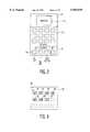
- FIG. 3shows a diagrammatic illustration of the external view of a remote control device
- FIG. 4shows the display of the possible remote control functions of a CD player on the display unit of the remote control device
- FIG. 5shows a rough block diagram of the remote control device
- FIG. 6shows a rough block diagram of an electronic device
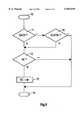
- FIG. 7shows a flow diagram for a program for a remote control device for the interrogation of the controllable devices
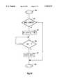
- FIG. 8shows a flow diagram for a program for an electronic device which is executed following the reception of an interrogation code
- FIG. 9shows a flow diagram for a program for a remote control device which is executed for the control request of an electronic device
- FIG. 10shows a flow diagram for a program which is executed following the reception of a control request in an electronic device
- FIG. 11shows the structure of an interrogation message which is transmitted from the remote control device
- FIG. 12shows the structure of an acknowledgement message which is transmitted from an electronic device following the reception of an interrogation message
- FIG. 13shows the structure of a control request message which is transmitted from a remote control device
- FIG. 14shows the structure of an information message which is transmitted from an electronic device following the reception of a control request message
- FIG. 15shows the structure of a control function message which is transmitted from the remote control device.
- FIG. 1illustrates a wide variety of terminals which are connected to one another via a digital data transmission channel.
- the reference number 10designates a satellite receiver.
- the reference number 11designates a television set which is connected to the broadband cable network.
- the reference number 12designates a television set which is connected to a house aerial.
- the reference number 13designates a fax machine.
- the reference number 14designates a modem.
- the reference number 15designates a radio device which is equipped with a wire aerial.
- the reference number 16designates a radio device which is likewise connected to the broadband cable network.
- the reference number 17designates a radio device which is connected to a house aerial.
- the reference number 18designates a third television set in the house.
- the reference number 19designates the amplifier of a stereo system.
- the reference number 20designates a video recorder.
- the reference number 21designates a CD player (CD in this case stands for Compact Disc).
- the reference number 22designates a printer.
- the reference number 23designates a telephone apparatus.
- the reference number 24designates a fourth television set.
- the reference number 25designates a computer.
- the reference number 26designates the digital data transmission channel. Also connected to the latter, finally, is a remote control device 27.
- the devices illustratedcan be provided, for example, in a house.
- the data transmission channel 26is at least partly of a wire-free design. All of the devices 10 to 25 illustrated can be remotely controlled by the remote control device 27.
- FIG. 2diagrammatically illustrates the same equipment interconnection as in FIG. 1.
- identical reference numbersdesignate the same components as in FIG. 1. These reference numbers are therefore not explained again.
- the reference number 28designates a communications interface.
- Each of the devices illustrated in FIG. 2contains a communications interface 28 of this type.
- Communications interfaces 28 of this typehave been sufficiently disclosed in the prior art. Reference is made in this respect to the serial interface designated RS232, or else an IIC bus interface (Inter-Integrated Circuit) or a CAN bus interface (Controller Area Network), which enjoy widespread application in computer technology.
- the communications interface 28contains circuits which realize a defined data transmission protocol. Such a transmission protocol can also be realized with the aid of programming measures and a microcomputer.
- the reference number 30designates the display unit of the remote control 27.
- the reference number 31designates a keypad.
- the keypad 31represents a freely programmable keypad.
- the reference number 32designates a further keypad.
- the keys contained thereinare fixed-programmed, they are each allocated a special function.
- the reference number 33in this case designates a selection key. A device to be controlled is selected using this selection key.
- the selection key 33can be actuated repeatedly. Each time this selection key 33 is actuated, a symbol of a different controllable device is displayed on the display unit 30.
- the reference number 34designates an interrogation key.
- the information data of the controllable devicescan be interrogated with the aid of this interrogation key 34. This key is actuated whenever another further device is to be added to the equipment interconnection illustrated in FIG. 2.
- the interrogation operationwill be explained in more detail below.
- the reference number 35designates a control request key. This key is actuated when the desired device to be controlled has been selected using the selection key 33. By pressing the control request key 35, a control request code is then communicated to the device to be controlled. Using this code, the corresponding device recognizes that it is to be subsequently controlled, and, as a response to this code, it communicates its specific information data relating to its control functions. This operation, too, will be explained in more detail below.
- FIG. 4now shows an image which is displayed on the display unit 30 and is provided for the remote control of a CD player.
- the CD symbol 40indicates that the displayed image is applicable to the remote control of a CD player.
- the reference number 41designates a playback symbol.
- the reference number 42designates a pause symbol.
- the reference number 43designates a symbol for a fast forward run and the reference number 44 designates a symbol for a fast reverse run.
- the reference number 45designates a forward skip symbol and the reference number 46 designates a reverse skip symbol.
- the reference number 47designates a stop symbol.
- the said symbols 41 to 47each indicate to the user a possible control function of the CD player. It goes without saying that even further symbols for further functions of a CD player could be provided here.
- the arrangement of the symbols 41 to 47is such that it coincides with the arrangement of the keys in the freely programmable keypad 31.
- the arrangement of the playback symbol in the top left corner of the display unit 30informs the user of the remote control 27, for example, of the fact that by pressing the top left key in the freely programmable keypad 31 he is activating the playback function of the CD player.
- FIG. 5illustrates a block diagram of the remote control 27.
- the reference number 50designates a receiving circuit. Receiving circuits of this type have been sufficiently disclosed in the prior art.
- the receiving circuitis one for infrared radiation.
- the receiving circuit 50is connected to a microcomputer 52.
- a transmitting circuit 51is furthermore provided.
- the transmitting circuittoo, has been generally disclosed in the prior art.
- the transmitting circuitis likewise one for infrared radiation.
- the transmitting circuit 51is also connected to the microcomputer 52.
- An operator unit 53is furthermore provided.
- the keypads 31 and 32are connected to the operator unit 53.
- the operator unit 53is also connected to the microcomputer 52.
- a memory unit 54is also provided.
- the microcomputer 52has access to the memory unit 54 via a bidirectional bus.
- the display unit 30is also illustrated.
- the display unit 30is likewise connected to the microcomputer 52.
- the memory unit 54is used as a data memory.
- the microcomputer 52additionally has a programmed memory in which, as has been sufficiently disclosed in the prior art, the data transmission protocol already mentioned above is stored.
- FIG. 6now illustrates a block diagram of the CD player 21. In this case, however, only the part relating to the communications interface 28 is illustrated in more detail. The remaining parts of the CD player are well known from the prior art.
- the reference numbers in FIG. 6correspond to the reference numbers in FIG. 5 and respectively designate the same components. It only remains to be mentioned, then, that a bidirectional bus issues from the microcomputer 52 and leads to the controller of the CD player.
- the reference number 60designates the program start, which is initiated by the actuation of the interrogation key 34.
- An interrogation codeis transmitted in the program step 61.
- the interrogation codeis transmitted with an interrogation message.
- the structure of the interrogation messageis illustrated in FIG. 11.
- the start bit(not illustrated) is followed by a source address field 100 in which the identification number of the remote control is entered as the source address.
- the source address field 100is followed by a control field 101.
- the manner in which the message is to be evaluatedis defined in this control field 101, by the code which is entered here.
- the control field 101thus determines the structure of the following fields, in particular the length and meaning thereof.
- the control field 101is followed by a destination address field 102. An identification number of an electronic device whose information data has already been read in during an earlier interrogation operation is entered into this field.
- the destination address field 102is then followed by a data field 103.
- An interrogation codeis stored in the latter.
- the device which receives the interrogation messageis thus informed that an interrogation operation is taking place and that it has to react accordingly.
- the data field 103is then also followed by a check code field 104. There is stored in the latter a check sum which can be used to verify error-free transmission of the message.
- the last thing to followis a stop bit, but it is not illustrated in FIG. 11.
- the interrogation code transmitted in program step 61is therefore intended for a specific electronic device and is accepted only by this electronic device.
- the remote controlwaits for a readiness message of the device addressed. If this message is received within a predetermined time, the program is continued with program step 61, in which case, however, a further electronic device is then interrogated whose device code has already previously been entered in the memory of the remote control. If no corresponding acknowledgement message arrives at the remote control within the predetermined time in program step 62, the associated device code is removed from the list in the memory 54. This is done in program step 63.
- interrogation messagesare likewise communicated to the other external devices whose device codes have been entered in the list of devices to be controlled in the memory 54 of the remote control. After the last of the devices has communicated its readiness code, the transmission of a further interrogation message ensues in the program step 64.
- this interrogation messageis likewise illustrated in FIG. 11.
- This messagehas the same structure as the interrogation message explained above. The difference is that a general device code is entered in the destination address field 102. From this code, all of the external devices which have previously not identified an interrogation message addressed to them within a predetermined time recognize that they are being requested to transmit an acknowledgement message. They then immediately communicate their acknowledgement message to the remote control device 27. In the program step 65, therefore, the remote control device 27 waits for the arrival of a further acknowledgement message. When such a message arrives, the associated device code is likewise entered in the list of remotely controllable devices in the memory 54. This then takes place in program step 66.
- each remotely controllable devicewhose device code has not yet been entered in the list of remotely controllable devices in the memory 54 of the remote control 27 generates a random number which determines the period of time after which the respective device transmits its acknowledgement message. In this way, data collisions are then avoided to the largest possible extent.
- this section of the programis ended in the program step 68. If no more acknowledgement messages have been received by the remote control 27 after a predetermined maximum time in the program step 65, the program is ended directly with program step 68.
- FIG. 8now shows the program sequence on the part of an electronic device 10 to 25, after it has received an interrogation message.
- the reference number 70designates the program start. This is initiated by the reception of an interrogation message.
- the received messageis thoroughly checked to see whether it contains the address of this device in the destination address field 103. If this address is contained in the destination address field 103, an interrogation is effected in the program step 72 to see whether the data field 103 contains the interrogation code. If this is likewise the case, then an acknowledgement message is transmitted back to the remote control 27. This is then done in program step 73. After this, the program is ended in program step 74.
- interrogation 71If it was discovered in interrogation 71 that the associated device address is not entered in the destination address field 102, an interrogation is effected in the program step 75 to see whether a general device address is entered in the corresponding destination address field 102. If this is the case, the program is continued with program step 72. If this is not the case, the program is immediately ended in the program step 74.
- FIG. 12shows the structure of an acknowledgement message.
- the structureis fundamentally the same as in FIG. 11.
- the same reference numbersdesignate the same as in FIG. 11.
- the device identification numberis entered in the source address field 100.
- the identification number of the remote controlis then entered as destination address in the destination address field 102.
- FIG. 9now illustrates a flow diagram for a program which is executed by the remote control device 27 following actuation of the control request key 35.
- the reference number 80designates the program start.
- the reference number 81then designates a program step in which a control request message is transmitted to the selected device.
- the structure of this control request messageis illustrated in FIG. 13.
- the special feature of this messageis that a remote control type code is additionally transmitted as well as the control request code in the data field 103. Since the data field 103 is longer in this case than in the preceding cases, a corresponding control code must also be entered in the control field 101.
- the identification number of the remote controlis entered in the source address field 100 and the device identification number is entered in the destination address field 102.
- program section 82there is an evaluation of the control information message which is then transmitted from the addressed device to the remote control.
- the evaluation of the control information items transmitted with the information messagethen takes place in program step 83.
- the transmitted function codes and meaning codesare entered in the memory 54 of the remote control.
- the displayis then also reconfigured in accordance with the received data, as illustrated in FIG. 4, for example.
- the programwaits in program step 84 for the actuation of a key of the keypad 31.
- the associated control codeis transmitted to the electronic device in the program step 85.
- the programis then continued again with program step 84 until it is ended by the actuation of another function key.
- FIG. 10now shows a flow diagram for an electronic device which has received the control request message.
- the programis started in the program step 90.
- interrogation 91a check is made to see whether the received control request message contains a control request code as well as a remote control type code and also the associated device identification number. If this is the case, the aforementioned information message is transmitted to the remote control device 27. This is then done in program step 92.
- the structure of the information messageis illustrated in FIG. 14.
- the device identification numberis entered in the source address field 100 of this message.
- the remote control identification numberis entered in the destination address field 102 of this message.
- a control code for the information messageis entered in the control field 101.
- the function codes and meaning codes of the remote control functions of the deviceare then successively entered in the data field 103 of this message.
- Information items regarding the input or output possibilities of the respective devicemay additionally be entered in the data field 103.
- Information items of this typeare, for example in the case of a video recorder, the information that the device has the following inputs for audio information items: namely a stereo channel, a mono channel and an input for a five-channel Dolby Surround program.
- the input possibility specifiedmay be the information "Input for video data" according to the PAL standard and/or according to the PAL Plus standard.
- the same details as for the input informationcan then be given as output information.
- these input and output information itemsthen have the following form, for example: as input possibilities, a mono input and a stereo input are made available for audio data.
- a PAL and/or PAL Plus inputis made available as input possibility for video data.
- the same information itemsare then considered as output possibilities.
- the ability of the television receiver to decode teletext datais also considered as an output possibility.
- control information itemsAfter the control information items have been transmitted to the remote control, the program waits in interrogation 93 to see whether a control function message arrives. If this is the case, the function assigned to the corresponding control code is executed. This is then done in the program step 94. This program section is then ended in program step 95.
- FIG. 15illustrates the structure of the control function message.
- the transmitted control codeis entered in the data field 103.
- the identification number of the remote controlis entered in the source address field 100.
- the device identification numberis entered in the destination address field 102.
- a dedicated identification numberis assigned to each remote control and also to each electronic device. Each individual device can be identified using this number. The numbers must be continually selected so that double allocations do not arise.
- One possible way of modifying this exemplary embodimentconsists in giving specific type identification numbers to the various devices. It is thus possible, for example, to give the same identification number both to all the television sets of one type, and to the CD players of one type, or the remote controls of one type, etc. Should two identical devices then appear in a multimedia interconnection, then it would be possible to distinguish between them only with difficulty. This would then require all of the devices to transmit a name proposal in their acknowledgement message to the remote control.
- remote controldetermines that such a name is already present in the memory, a different name would then automatically have to be selected and would then also have to be communicated to the device to be controlled in a separate message. Mix-ups can then be avoided in this way. Each device must then answer again in future under the respective name.
- the information datado not necessarily have to be transmitted in a wire-free manner to the remote control device. If, for example, the individual devices of the equipment interconnection are accommodated in different rooms and all of the devices are connected to one another via a separate data network, the information data can also be transmitted to the remote control device via this data network. The remote control device must then likewise be connected to this data network.
- the power supply systemcan also be considered as a data network. The devices are connected to the said power supply system in any case. The remote control device must then likewise be connected to the power supply system.
- a telephone network or a radio networkcan also be used as a data network for transmitting the information items.
- the field of applicationis also extended to include remote control functions such as, for example, the switching on of an alarm system or of a heating installation, etc. with the aid of the remote control.
- the remote controlcan also be designed in such a way that it is of portable design, on the one hand, but also has an interface for data reception via the data network (power supply system) in order to receive the information data of a large number of devices which do not have an infrared transmitter.
- the remote control deviceis temporarily connected to the data network for this purpose. After it has received these data, it can control the devices in a wire-free manner if the devices are designed for this.
- the individual devices 10 to 25may exchange data between one another in accordance with the same communications protocol.
- datamay be, for example, video data and audio data.
- the datamay also be selected data, for example regarding the programming of a video recorder.
- graphical data for driving the display unit 30could also be transmitted.
- the individual datacould then be bit map information items. These data could then be displayed on a touch-sensitive screen. The operator would then only have to touch the corresponding area of the screen in order to initiate a remote control operation. A voice output of the received data at the remote control would also be possible.
- a further possible modificationconsists in the information data being transmitted to the remote control device as early as after the reception of the interrogation message.
- the remote controlwould then store these data immediately in the memory.
- a separate control request keywould not then be necessary. However, a larger memory would be necessary.
Landscapes
- Engineering & Computer Science (AREA)
- Computer Networks & Wireless Communication (AREA)
- Signal Processing (AREA)
- Selective Calling Equipment (AREA)
Abstract
Description
Claims (9)
Applications Claiming Priority (2)
| Application Number | Priority Date | Filing Date | Title |
|---|---|---|---|
| DE19548776ADE19548776A1 (en) | 1995-12-23 | 1995-12-23 | Method for remote control of electronic devices and device for remote control of electronic devices and electronic device |
| DE19548776 | 1995-12-23 |
Publications (1)
| Publication Number | Publication Date |
|---|---|
| US5959539Atrue US5959539A (en) | 1999-09-28 |
Family
ID=7781447
Family Applications (1)
| Application Number | Title | Priority Date | Filing Date |
|---|---|---|---|
| US08/763,561Expired - LifetimeUS5959539A (en) | 1995-12-23 | 1996-12-10 | Apparatus for the remote control of electronic devices with key allocation |
Country Status (5)
| Country | Link |
|---|---|
| US (1) | US5959539A (en) |
| EP (1) | EP0780990B1 (en) |
| JP (2) | JPH09187085A (en) |
| CN (1) | CN1105433C (en) |
| DE (2) | DE19548776A1 (en) |
Cited By (86)
| Publication number | Priority date | Publication date | Assignee | Title |
|---|---|---|---|---|
| US6097309A (en)* | 1998-07-23 | 2000-08-01 | Universal Electronics Inc. | Remote control learning system and method using signal envelope pattern recognition |
| US6133847A (en)* | 1997-10-09 | 2000-10-17 | At&T Corp. | Configurable remote control device |
| US6157319A (en)* | 1998-07-23 | 2000-12-05 | Universal Electronics Inc. | Universal remote control system with device activated setup |
| US6225938B1 (en) | 1999-01-14 | 2001-05-01 | Universal Electronics Inc. | Universal remote control system with bar code setup |
| EP1111911A1 (en)* | 1999-12-21 | 2001-06-27 | Grundig AG | Device for remote controlling of a television receiver or a videorecorder |
| US6285357B1 (en)* | 1997-09-25 | 2001-09-04 | Mitsubishi Denki Kabushiki Kaisha | Remote control device |
| EP1133830A1 (en)* | 1999-09-24 | 2001-09-19 | Koninklijke Philips Electronics N.V. | Universal remote control unit |
| WO2001024451A3 (en)* | 1999-09-30 | 2001-10-11 | Siemens Ag | Remote control conversion method |
| US20020033760A1 (en)* | 2000-09-18 | 2002-03-21 | Shinji Kobayashi | Portable information divice, access device for portable information device, home network system, and home network access method |
| US20020047774A1 (en)* | 2000-04-10 | 2002-04-25 | Christensen Carlos Melia | RF home automation system with replicable controllers |
| US6392964B2 (en)* | 1997-09-19 | 2002-05-21 | Sony Corporation | Digital signal recording/reproducing apparatus and remote controlling apparatus capable of displaying program names in a plurality of display fields using different character symbols and recording and reproducing methods thereof |
| US6492909B1 (en)* | 1997-09-10 | 2002-12-10 | Sony Corporation | Audio signal processing apparatus |
| WO2003015451A1 (en) | 2001-08-02 | 2003-02-20 | Sony Corporation | Remote operation system, remote operation method, apparatus for performing remote operation and control method thereof, apparatus operated by remote operation and control method thereof, and recording medium |
| US6544228B1 (en)* | 1999-12-24 | 2003-04-08 | B. Braun Melsungen Ag | Infusion device comprising a plurality of infusion pumps |
| US6636899B1 (en)* | 1998-09-24 | 2003-10-21 | Xerox Corporation | Architecture for software for remote maintenance of a machine such as a copier |
| US6650247B1 (en) | 2002-02-20 | 2003-11-18 | Universal Electronics Inc. | System and method for configuring a home appliance communications network |
| FR2840717A1 (en)* | 2002-06-11 | 2003-12-12 | Somfy | Building equipment control device configuration having transmitter/receiver with command sent transmitter with ergonomic features and receiver comparing features with list/translating commands equipment executables |
| US20040002779A1 (en)* | 2002-07-01 | 2004-01-01 | Noriko Shimba | Home electrical appliance control device, control method, control program and home electrical appliance |
| US20040032495A1 (en)* | 2000-10-26 | 2004-02-19 | Ortiz Luis M. | Providing multiple synchronized camera views for broadcast from a live venue activity to remote viewers |
| US6784804B1 (en)* | 1998-07-23 | 2004-08-31 | Universal Electronics Inc. | Digital interconnect of entertainment equipment |
| US20050009173A1 (en)* | 2001-11-29 | 2005-01-13 | Frank Amand | System for remote control of identical devices |
| US20050088275A1 (en)* | 2002-02-11 | 2005-04-28 | Francis Valoteau | Method for matching bidirectional objects |
| US20050120096A1 (en)* | 2001-08-02 | 2005-06-02 | Junichi Rekimoto | Remote control system and remote control method, device for performing remote control operation and control method therefor, device operable by remote control operation and control method therefor, and storage medium |
| US20050140521A1 (en)* | 2003-12-29 | 2005-06-30 | Benq Corporation | Method for controlling an electronic device from a distance via a command controller |
| US20050273828A1 (en)* | 1999-12-21 | 2005-12-08 | Tivo Inc. | Method for enhancing digital video recorder television advertising viewership |
| US20060048194A1 (en)* | 2004-08-26 | 2006-03-02 | Thomas Poslinski | Network remote control |
| WO2006048435A1 (en)* | 2004-11-03 | 2006-05-11 | E.C.E. Sa (Etude Concept Electronique) | Remote control method and device |
| US20060109138A1 (en)* | 2004-11-23 | 2006-05-25 | Shao-Pin Chiang | Apparatus and method for interactive touch screen remote control |
| FR2878638A1 (en)* | 2004-11-03 | 2006-06-02 | Etude Concept Electronique Sa | Remote control code transmitter for e.g. controlling receivers, has keyboard on which identifier of receiver to be controlled is input, and memories to respectively store input identifier and identification code of transmitter |
| US20060132287A1 (en)* | 2004-12-16 | 2006-06-22 | Xerox Corporation | Radio frequency identification interrogation method and radio frequency identification device |
| US20060143546A1 (en)* | 2004-12-15 | 2006-06-29 | Samsung Electronics Co., Ltd. | Method and apparatus for performing external device's diagnostic functions in host computer |
| US7113228B1 (en) | 1999-07-07 | 2006-09-26 | Thomson Licensing | Modular control panel for video apparatus |
| US20060267726A1 (en)* | 2005-05-31 | 2006-11-30 | Sony Corporation | Remote controller, equipment operation system, and remote control method |
| EP1736948A1 (en)* | 2005-06-21 | 2006-12-27 | Mitac Technology Corp. | Apparatus and method for remotely controlling an appliance using a touch screen |
| EP1290653A4 (en)* | 2000-03-23 | 2007-06-27 | Flextronics Semiconductor Inc | METHOD, DEVICE AND SYSTEM FOR THE ADAPTIVE, INTERACTIVE AND UNIVERSAL REMOTE CONTROL OF DEVICES |
| US20070246553A1 (en)* | 2006-04-22 | 2007-10-25 | International Controls And Measurements Corp. | Reconfigurable programmable thermostat |
| US20080065768A1 (en)* | 2000-06-27 | 2008-03-13 | Ortiz Luis M | Processing of entertainment venue-based data utilizing wireless hand held devices |
| US20080158003A1 (en)* | 2006-12-29 | 2008-07-03 | John William Linebarger | Two-way communication for control of an entertainment device |
| US20080157936A1 (en)* | 2005-06-09 | 2008-07-03 | Whirlpool Corporation | Appliance Network for a Networked Appliance and a Remote User Interface |
| US20090008228A1 (en)* | 2007-06-07 | 2009-01-08 | Ming-Tsai Wang | Power saving device for power source |
| US20090009605A1 (en)* | 2000-06-27 | 2009-01-08 | Ortiz Luis M | Providing multiple video perspectives of activities through a data network to a remote multimedia server for selective display by remote viewing audiences |
| US20090040016A1 (en)* | 2007-08-10 | 2009-02-12 | Sony Corporation | Remote controller, remote control system, and remote control method |
| US20090086110A1 (en)* | 2007-10-01 | 2009-04-02 | Echostar Technologies Corporation | Remote control device and method employing random addressing |
| US20090102696A1 (en)* | 2007-10-18 | 2009-04-23 | Samsung Electronics Co., Ltd. | Universal remote control apparatus, system for controlling universal remote control, and method for the same based on batch instruction |
| US20090195407A1 (en)* | 2008-02-04 | 2009-08-06 | Sony Corporation | Remote controlling apparatus, reception apparatus, and remote control method |
| US20090251280A1 (en)* | 2006-03-07 | 2009-10-08 | Nice S.P.A. | Radio Receiver and Transmitter Apparatus for Radio-Controlled Automation Systems for Opening/Closure |
| US20090251559A1 (en)* | 2002-11-20 | 2009-10-08 | Koninklijke Philips Electronics N.V. | User interface system based on pointing device |
| US7640351B2 (en) | 2005-11-04 | 2009-12-29 | Intermatic Incorporated | Application updating in a home automation data transfer system |
| WO2010028230A1 (en)* | 2008-09-08 | 2010-03-11 | Universal Electronics Inc. | Two way communication between an appliance and a remote control |
| US20100060791A1 (en)* | 2001-05-03 | 2010-03-11 | Mitsubishi Digital Electronics America, Inc. | Control system and user interface for network of input devices |
| US7694005B2 (en) | 2005-11-04 | 2010-04-06 | Intermatic Incorporated | Remote device management in a home automation data transfer system |
| US7698448B2 (en) | 2005-11-04 | 2010-04-13 | Intermatic Incorporated | Proxy commands and devices for a home automation data transfer system |
| US20100150532A1 (en)* | 2000-01-11 | 2010-06-17 | Nobukazu Sugiyama | Electronic device system |
| US20100157171A1 (en)* | 1998-07-23 | 2010-06-24 | Universal Electronics Inc. | Digital interconnect of entertainment equipment in the home |
| US7812856B2 (en) | 2000-10-26 | 2010-10-12 | Front Row Technologies, Llc | Providing multiple perspectives of a venue activity to electronic wireless hand held devices |
| US7870232B2 (en) | 2005-11-04 | 2011-01-11 | Intermatic Incorporated | Messaging in a home automation data transfer system |
| EP1677269A3 (en)* | 2004-12-31 | 2011-01-12 | LG Electronics Inc. | Remote control signal, remote control system, and method of controlling device with remote controller |
| US20110033167A1 (en)* | 2000-11-21 | 2011-02-10 | Universal Electronics Inc. | Media return system |
| US8098140B1 (en) | 2000-07-13 | 2012-01-17 | Universal Electronics Inc. | Customizable and upgradable devices and methods related thereto |
| US20120178371A1 (en)* | 2010-07-23 | 2012-07-12 | Mukesh Patel | Automatic updates to a remote control device |
| US20120256737A1 (en)* | 2011-04-11 | 2012-10-11 | Electronics And Telecommunications Research Institute | Portable terminal with remote control function and method of performing remote control using the same |
| US20130265501A1 (en)* | 2012-04-09 | 2013-10-10 | Sony Corporation | Remote touch gestures |
| US8583027B2 (en) | 2000-10-26 | 2013-11-12 | Front Row Technologies, Llc | Methods and systems for authorizing computing devices for receipt of venue-based data based on the location of a user |
| US20140009689A1 (en)* | 2001-01-29 | 2014-01-09 | Universal Electronics Inc. | System and method for using a mark-up language page to command an appliance |
| US8653951B2 (en) | 2010-11-24 | 2014-02-18 | Industrial Technology Research Institute | Method, system and devices for remote control and be-controlled |
| US8659400B2 (en) | 2006-09-05 | 2014-02-25 | Universal Electronics Inc. | System and method for configuring the remote control functionality of a portable device |
| US8786411B1 (en)* | 2003-10-02 | 2014-07-22 | Tivo Inc. | Remote control programming system |
| US20140218622A1 (en)* | 2011-12-28 | 2014-08-07 | Sanyo Electric Co., Ltd. | Video display device and external device |
| US8812629B2 (en) | 2008-04-18 | 2014-08-19 | Universal Electronics Inc. | System and method for configuring the remote control functionality of a portable device |
| US8837259B2 (en) | 2011-10-19 | 2014-09-16 | Cggveritas Services Sa | Source for marine seismic acquisition and method |
| US8976303B2 (en)* | 2012-08-22 | 2015-03-10 | Sony Corporation | Presenting snapshot of controlled device display on display of remote commander to facilitate control of the controlled device by user who cannot see controlled device |
| US9208679B2 (en) | 2006-09-05 | 2015-12-08 | Universal Electronics Inc. | System and method for configuring the remote control functionality of a portable device |
| US9350850B2 (en) | 2008-04-18 | 2016-05-24 | Uei Cayman Inc. | Using HDMI-CEC to identify a codeset |
| US20160191838A1 (en)* | 2011-10-28 | 2016-06-30 | Universal Electronics Inc. | System and method for optimized appliance control |
| US20170024999A1 (en)* | 1998-07-23 | 2017-01-26 | Universal Electronics Inc. | System and method for automatically setting up a universal remote control |
| US9646444B2 (en) | 2000-06-27 | 2017-05-09 | Mesa Digital, Llc | Electronic wireless hand held multimedia device |
| US10148900B2 (en) | 2014-07-16 | 2018-12-04 | Alibaba Group Holding Limited | Controlling one or more source terminals based on remote control information |
| US10217352B2 (en) | 2008-04-18 | 2019-02-26 | Universal Electronics Inc. | System and method for appliance control via a network |
| US10325487B2 (en) | 2011-10-28 | 2019-06-18 | Universal Electronics Inc. | System and method for optimized appliance control |
| US10593195B2 (en) | 2011-10-28 | 2020-03-17 | Universal Electronics Inc. | System and method for optimized appliance control |
| US10896600B2 (en)* | 2017-10-16 | 2021-01-19 | Universal Electronics Inc. | Apparatus, system and method for using a universal controlling device for displaying a graphical user element in a display device |
| US10937308B2 (en) | 2011-10-28 | 2021-03-02 | Universal Electronics Inc. | System and method for optimized appliance control |
| US11295603B2 (en) | 2011-10-28 | 2022-04-05 | Universal Electronics Inc. | System and method for optimized appliance control |
| US12154428B2 (en) | 2005-09-08 | 2024-11-26 | Universal Electronics Inc. | System and method for widget-assisted setup of a universal remote control |
| US12192559B2 (en) | 2011-09-22 | 2025-01-07 | Universal Electronics Inc. | System and method for configuring controlling device functionality |
| US12307884B2 (en) | 2011-10-28 | 2025-05-20 | Universal Electronics Inc. | Systems and methods for associating services and/or devices with a voice assistant |
Families Citing this family (15)
| Publication number | Priority date | Publication date | Assignee | Title |
|---|---|---|---|---|
| US6667992B1 (en) | 1997-08-04 | 2003-12-23 | Matsushita Electric Industrial Co., Ltd. | Network control system |
| US7218243B2 (en) | 1998-07-23 | 2007-05-15 | Universal Electronics Inc. | System and method for automatically setting up a universal remote control |
| US6434447B1 (en)* | 1998-10-02 | 2002-08-13 | Koninklijke Philips Electronics N.V. | Control property is mapped modally compatible GUI element |
| US6757906B1 (en) | 1999-03-30 | 2004-06-29 | Tivo, Inc. | Television viewer interface system |
| US8689265B2 (en) | 1999-03-30 | 2014-04-01 | Tivo Inc. | Multimedia mobile personalization system |
| US6507762B1 (en)* | 1999-03-31 | 2003-01-14 | International Business Machines Corporation | Method and system for remotely controlling an appliance using a personal digital assistant |
| DE19935004A1 (en)* | 1999-07-26 | 2001-05-17 | Infineon Technologies Ag | Remote control arrangement, device to be operated remotely, control device for remote control and household appliance |
| JP4854121B2 (en)* | 2001-03-08 | 2012-01-18 | オンセミコンダクター・トレーディング・リミテッド | IIC bus control circuit |
| US7154566B2 (en)* | 2002-12-05 | 2006-12-26 | Koninklijke Philips Electronics N.V. | Programmable universal remote control unit and method of programming same |
| DE10353564A1 (en)* | 2003-11-14 | 2005-06-16 | Deutsche Thomson-Brandt Gmbh | Method for the intermittent, discontinuous transmission of data in a network of distributed stations and network subscriber station as a request device in the implementation of such a method as well as network subscriber station as a source device in the implementation of such a method |
| EP1622312A1 (en)* | 2004-07-29 | 2006-02-01 | Sun Microsystems France S.A. | Method and apparatus for discovering wireless devices in a wireless network |
| CN100438586C (en)* | 2004-08-28 | 2008-11-26 | 康佳集团股份有限公司 | Method for reading/writing data using remote controller in TV set |
| CN101814230A (en)* | 2010-04-01 | 2010-08-25 | 青岛海信电器股份有限公司 | Serial data communication transmitting method and device |
| CN101938595A (en)* | 2010-09-15 | 2011-01-05 | 福建新大陆通信科技股份有限公司 | Flash storage-based remote control self-learning method |
| CN111085999B (en)* | 2019-12-18 | 2022-11-15 | 达闼机器人股份有限公司 | Robot control method, device and system and robot controller |
Citations (10)
| Publication number | Priority date | Publication date | Assignee | Title |
|---|---|---|---|---|
| US4566034A (en)* | 1983-05-02 | 1986-01-21 | Rca Corporation | Remote control transmitter arrangement for one or more television devices |
| US4728949A (en)* | 1983-03-23 | 1988-03-01 | Telefunken Fernseh Und Rundfunk Gmbh | Remote control device for controlling various functions of one or more appliances |
| US4746919A (en)* | 1986-03-28 | 1988-05-24 | Rca Licensing Corporation | Remote control system with key function display provisions |
| US4764981A (en)* | 1985-05-29 | 1988-08-16 | Alps Electric Co., Ltd. | Remote control circuit |
| US4773005A (en)* | 1984-09-07 | 1988-09-20 | Tektronix, Inc. | Dynamic address assignment system |
| US4825209A (en)* | 1985-03-06 | 1989-04-25 | Alps Electric Co., Ltd | Remote control apparatus |
| DE4042129A1 (en)* | 1989-12-30 | 1991-07-11 | Gold Star Co | Send-receive procedure for remote control device - processing keyed signals with stored key code and sign code enabling several electrical appliances to be operated by single control |
| GB2275800A (en)* | 1993-03-05 | 1994-09-07 | Pioneer Electronic Corp | Remote control system for controlling a plurality of devices |
| US5351041A (en)* | 1990-10-25 | 1994-09-27 | Pioneer Electronic Corporation | Method of data communication in communication network on automobile |
| US5621484A (en)* | 1994-05-18 | 1997-04-15 | U.S. Philips Corporation | User-programmable control device for a television apparatus |
Family Cites Families (10)
| Publication number | Priority date | Publication date | Assignee | Title |
|---|---|---|---|---|
| US5282028A (en) | 1990-11-27 | 1994-01-25 | Scientific-Atlanta, Inc. | Remote control for digital music terminal with synchronized communications |
| JP2590468Y2 (en)* | 1992-02-25 | 1999-02-17 | 株式会社ケンウッド | Wireless communication equipment |
| JP3272046B2 (en)* | 1992-09-22 | 2002-04-08 | 三洋電機株式会社 | Remote control transmitter, operation target device operated and controlled by the remote control transmitter, and remote control system using them |
| US5410326A (en)* | 1992-12-04 | 1995-04-25 | Goldstein; Steven W. | Programmable remote control device for interacting with a plurality of remotely controlled devices |
| JPH06213496A (en)* | 1993-01-12 | 1994-08-02 | Toshiba Corp | Air conditioner |
| EP0626635B1 (en)* | 1993-05-24 | 2003-03-05 | Sun Microsystems, Inc. | Improved graphical user interface with method for interfacing to remote devices |
| JPH07111508A (en)* | 1993-10-12 | 1995-04-25 | Matsushita Electric Ind Co Ltd | Transceiver |
| JP3035877B2 (en)* | 1993-11-10 | 2000-04-24 | 松下電器産業株式会社 | Remote control device |
| JP3347861B2 (en)* | 1994-02-28 | 2002-11-20 | コーナンエンジニアリング株式会社 | Remote control device |
| JPH07303190A (en)* | 1994-05-06 | 1995-11-14 | Ricoh Co Ltd | Image processing device |
- 1995
- 1995-12-23DEDE19548776Apatent/DE19548776A1/ennot_activeWithdrawn
- 1996
- 1996-12-10USUS08/763,561patent/US5959539A/ennot_activeExpired - Lifetime
- 1996-12-16EPEP96120167Apatent/EP0780990B1/ennot_activeExpired - Lifetime
- 1996-12-16JPJP8336136Apatent/JPH09187085A/enactivePending
- 1996-12-16DEDE59611109Tpatent/DE59611109D1/ennot_activeExpired - Lifetime
- 1996-12-18CNCN96123133Apatent/CN1105433C/ennot_activeExpired - Lifetime
- 2006
- 2006-09-27JPJP2006262695Apatent/JP2007006534A/enactivePending
Patent Citations (10)
| Publication number | Priority date | Publication date | Assignee | Title |
|---|---|---|---|---|
| US4728949A (en)* | 1983-03-23 | 1988-03-01 | Telefunken Fernseh Und Rundfunk Gmbh | Remote control device for controlling various functions of one or more appliances |
| US4566034A (en)* | 1983-05-02 | 1986-01-21 | Rca Corporation | Remote control transmitter arrangement for one or more television devices |
| US4773005A (en)* | 1984-09-07 | 1988-09-20 | Tektronix, Inc. | Dynamic address assignment system |
| US4825209A (en)* | 1985-03-06 | 1989-04-25 | Alps Electric Co., Ltd | Remote control apparatus |
| US4764981A (en)* | 1985-05-29 | 1988-08-16 | Alps Electric Co., Ltd. | Remote control circuit |
| US4746919A (en)* | 1986-03-28 | 1988-05-24 | Rca Licensing Corporation | Remote control system with key function display provisions |
| DE4042129A1 (en)* | 1989-12-30 | 1991-07-11 | Gold Star Co | Send-receive procedure for remote control device - processing keyed signals with stored key code and sign code enabling several electrical appliances to be operated by single control |
| US5351041A (en)* | 1990-10-25 | 1994-09-27 | Pioneer Electronic Corporation | Method of data communication in communication network on automobile |
| GB2275800A (en)* | 1993-03-05 | 1994-09-07 | Pioneer Electronic Corp | Remote control system for controlling a plurality of devices |
| US5621484A (en)* | 1994-05-18 | 1997-04-15 | U.S. Philips Corporation | User-programmable control device for a television apparatus |
Non-Patent Citations (6)
| Title |
|---|
| Audio and Video in Home Networks, Funkschau Jun. 1991,pp. 74 79, Germany.* |
| Audio and Video in Home Networks, Funkschau Jun. 1991,pp. 74-79, Germany. |
| Continuous Dialog with Audio and Video, Funkschau, Jan. 1991, pp. 53 55, Germany.* |
| Continuous Dialog with Audio and Video, Funkschau, Jan. 1991, pp. 53-55, Germany. |
| Tomohiro Hase, Morimasa Matsuda, A New Audio Visual Control Using Message Object Transmission, Abstract, IEE Transactions on Consumer Electronics, vol. 40, No. 4, Nov. 1994.* |
| Tomohiro Hase, Morimasa Matsuda, A New Audio-Visual Control Using Message Object Transmission, Abstract, IEE Transactions on Consumer Electronics, vol. 40, No. 4, Nov. 1994. |
Cited By (190)
| Publication number | Priority date | Publication date | Assignee | Title |
|---|---|---|---|---|
| US6492909B1 (en)* | 1997-09-10 | 2002-12-10 | Sony Corporation | Audio signal processing apparatus |
| US6392964B2 (en)* | 1997-09-19 | 2002-05-21 | Sony Corporation | Digital signal recording/reproducing apparatus and remote controlling apparatus capable of displaying program names in a plurality of display fields using different character symbols and recording and reproducing methods thereof |
| US6285357B1 (en)* | 1997-09-25 | 2001-09-04 | Mitsubishi Denki Kabushiki Kaisha | Remote control device |
| US6133847A (en)* | 1997-10-09 | 2000-10-17 | At&T Corp. | Configurable remote control device |
| US20170024999A1 (en)* | 1998-07-23 | 2017-01-26 | Universal Electronics Inc. | System and method for automatically setting up a universal remote control |
| US7119710B2 (en)* | 1998-07-23 | 2006-10-10 | Universal Electronics Inc. | Digital interconnect of entertainment equipment |
| US6781518B1 (en) | 1998-07-23 | 2004-08-24 | Universal Electronics Inc. | Digital interconnect of entertainment equipment |
| US9818293B2 (en)* | 1998-07-23 | 2017-11-14 | Universal Electronics Inc. | System and method for automatically setting up a universal remote control |
| US7319409B2 (en) | 1998-07-23 | 2008-01-15 | Universal Electronics | Digital interconnect of entertainment equipment |
| US8558676B2 (en) | 1998-07-23 | 2013-10-15 | Universal Electronics Inc. | Digital interconnect of entertainment equipment in the home |
| US6157319A (en)* | 1998-07-23 | 2000-12-05 | Universal Electronics Inc. | Universal remote control system with device activated setup |
| US20100157171A1 (en)* | 1998-07-23 | 2010-06-24 | Universal Electronics Inc. | Digital interconnect of entertainment equipment in the home |
| US6784804B1 (en)* | 1998-07-23 | 2004-08-31 | Universal Electronics Inc. | Digital interconnect of entertainment equipment |
| US20050024226A1 (en)* | 1998-07-23 | 2005-02-03 | Universal Electronics Inc. | Digital interconnect of entertainment equipment |
| US20050285750A1 (en)* | 1998-07-23 | 2005-12-29 | Universal Electronics Inc. | Digital interconnect of entertainment equipment |
| US6097309A (en)* | 1998-07-23 | 2000-08-01 | Universal Electronics Inc. | Remote control learning system and method using signal envelope pattern recognition |
| US6636899B1 (en)* | 1998-09-24 | 2003-10-21 | Xerox Corporation | Architecture for software for remote maintenance of a machine such as a copier |
| US6225938B1 (en) | 1999-01-14 | 2001-05-01 | Universal Electronics Inc. | Universal remote control system with bar code setup |
| US7113228B1 (en) | 1999-07-07 | 2006-09-26 | Thomson Licensing | Modular control panel for video apparatus |
| EP1133830A1 (en)* | 1999-09-24 | 2001-09-19 | Koninklijke Philips Electronics N.V. | Universal remote control unit |
| WO2001024451A3 (en)* | 1999-09-30 | 2001-10-11 | Siemens Ag | Remote control conversion method |
| US20050273828A1 (en)* | 1999-12-21 | 2005-12-08 | Tivo Inc. | Method for enhancing digital video recorder television advertising viewership |
| EP1111911A1 (en)* | 1999-12-21 | 2001-06-27 | Grundig AG | Device for remote controlling of a television receiver or a videorecorder |
| US6544228B1 (en)* | 1999-12-24 | 2003-04-08 | B. Braun Melsungen Ag | Infusion device comprising a plurality of infusion pumps |
| US20100150532A1 (en)* | 2000-01-11 | 2010-06-17 | Nobukazu Sugiyama | Electronic device system |
| EP1290653A4 (en)* | 2000-03-23 | 2007-06-27 | Flextronics Semiconductor Inc | METHOD, DEVICE AND SYSTEM FOR THE ADAPTIVE, INTERACTIVE AND UNIVERSAL REMOTE CONTROL OF DEVICES |
| US6980080B2 (en)* | 2000-04-10 | 2005-12-27 | Zensys A/S | RF home automation system with replicable controllers |
| US20020047774A1 (en)* | 2000-04-10 | 2002-04-25 | Christensen Carlos Melia | RF home automation system with replicable controllers |
| US8184169B2 (en) | 2000-06-27 | 2012-05-22 | Front Row Technologies, Llc | Providing multiple video perspectives of activities through a data network to a remote multimedia server for selective display by remote viewing audiences |
| US9646444B2 (en) | 2000-06-27 | 2017-05-09 | Mesa Digital, Llc | Electronic wireless hand held multimedia device |
| US20090009605A1 (en)* | 2000-06-27 | 2009-01-08 | Ortiz Luis M | Providing multiple video perspectives of activities through a data network to a remote multimedia server for selective display by remote viewing audiences |
| US8610786B2 (en) | 2000-06-27 | 2013-12-17 | Front Row Technologies, Llc | Providing multiple video perspectives of activities through a data network to a remote multimedia server for selective display by remote viewing audiences |
| US20080065768A1 (en)* | 2000-06-27 | 2008-03-13 | Ortiz Luis M | Processing of entertainment venue-based data utilizing wireless hand held devices |
| US20100289900A1 (en)* | 2000-06-27 | 2010-11-18 | Ortiz Luis M | Providing multiple video perspectives of activities through a data network to a remote multimedia server for selective display by remote viewing audiences |
| US7782363B2 (en) | 2000-06-27 | 2010-08-24 | Front Row Technologies, Llc | Providing multiple video perspectives of activities through a data network to a remote multimedia server for selective display by remote viewing audiences |
| US8098140B1 (en) | 2000-07-13 | 2012-01-17 | Universal Electronics Inc. | Customizable and upgradable devices and methods related thereto |
| US20020033760A1 (en)* | 2000-09-18 | 2002-03-21 | Shinji Kobayashi | Portable information divice, access device for portable information device, home network system, and home network access method |
| US7142128B2 (en)* | 2000-09-18 | 2006-11-28 | Sony Corporation | Portable information device, access device for portable information device, home network system, and home network access method |
| US8750784B2 (en) | 2000-10-26 | 2014-06-10 | Front Row Technologies, Llc | Method, system and server for authorizing computing devices for receipt of venue-based data based on the geographic location of a user |
| US10129569B2 (en) | 2000-10-26 | 2018-11-13 | Front Row Technologies, Llc | Wireless transmission of sports venue-based data including video to hand held devices |
| US8090321B2 (en) | 2000-10-26 | 2012-01-03 | Front Row Technologies, Llc | Transmitting sports and entertainment data to wireless hand held devices over a telecommunications network |
| US8086184B2 (en) | 2000-10-26 | 2011-12-27 | Front Row Technologies, Llc | Transmitting sports and entertainment data to wireless hand held devices over a telecommunications network |
| US7884855B2 (en) | 2000-10-26 | 2011-02-08 | Front Row Technologies, Llc | Displaying broadcasts of multiple camera perspective recordings from live activities at entertainment venues on remote video monitors |
| US7826877B2 (en) | 2000-10-26 | 2010-11-02 | Front Row Technologies, Llc | Transmitting sports and entertainment data to wireless hand held devices over a telecommunications network |
| US8270895B2 (en) | 2000-10-26 | 2012-09-18 | Front Row Technologies, Llc | Transmitting sports and entertainment data to wireless hand held devices over a telecommunications network |
| US7812856B2 (en) | 2000-10-26 | 2010-10-12 | Front Row Technologies, Llc | Providing multiple perspectives of a venue activity to electronic wireless hand held devices |
| US7796162B2 (en) | 2000-10-26 | 2010-09-14 | Front Row Technologies, Llc | Providing multiple synchronized camera views for broadcast from a live venue activity to remote viewers |
| US20040032495A1 (en)* | 2000-10-26 | 2004-02-19 | Ortiz Luis M. | Providing multiple synchronized camera views for broadcast from a live venue activity to remote viewers |
| US8319845B2 (en) | 2000-10-26 | 2012-11-27 | Front Row Technologies | In-play camera associated with headgear used in sporting events and configured to provide wireless transmission of captured video for broadcast to and display at remote video monitors |
| US8401460B2 (en) | 2000-10-26 | 2013-03-19 | Front Row Technologies, Llc | Transmitting sports and entertainment data to wireless hand held devices over a telecommunications network |
| US8583027B2 (en) | 2000-10-26 | 2013-11-12 | Front Row Technologies, Llc | Methods and systems for authorizing computing devices for receipt of venue-based data based on the location of a user |
| US20110033167A1 (en)* | 2000-11-21 | 2011-02-10 | Universal Electronics Inc. | Media return system |
| US9100612B2 (en)* | 2000-11-21 | 2015-08-04 | Universal Electronics Inc. | Media return system |
| US20140009689A1 (en)* | 2001-01-29 | 2014-01-09 | Universal Electronics Inc. | System and method for using a mark-up language page to command an appliance |
| US8134650B2 (en)* | 2001-05-03 | 2012-03-13 | Mitsubishi Electric Visual Solutions America, Inc. | Control system and user interface for network of input devices |
| US20100060791A1 (en)* | 2001-05-03 | 2010-03-11 | Mitsubishi Digital Electronics America, Inc. | Control system and user interface for network of input devices |
| US20050120096A1 (en)* | 2001-08-02 | 2005-06-02 | Junichi Rekimoto | Remote control system and remote control method, device for performing remote control operation and control method therefor, device operable by remote control operation and control method therefor, and storage medium |
| EP1414264A4 (en)* | 2001-08-02 | 2008-12-10 | Sony Corp | Remote operation system, remote operation method, apparatus for performing remote operation and control method thereof, apparatus operated by remote operation and control method thereof, and recording medium |
| WO2003015451A1 (en) | 2001-08-02 | 2003-02-20 | Sony Corporation | Remote operation system, remote operation method, apparatus for performing remote operation and control method thereof, apparatus operated by remote operation and control method thereof, and recording medium |
| EP2334095A3 (en)* | 2001-08-02 | 2012-01-11 | Sony Corporation | Remote control system and remote control method, device for performing remote control operation and control method therefor, device operable by remote control operation and control method thereof, and storage medium |
| US9913007B2 (en) | 2001-08-02 | 2018-03-06 | Sony Corporation | Remote control system and remote control method, device for performing remote control operation and control method therefor, device operable by remote control operation and control method therefor, and storage medium |
| US8190695B2 (en) | 2001-08-02 | 2012-05-29 | Sony Corporation | Remote control system and remote control method, device for performing remote control operation and control method therefor, device operable by remote control operation and control method therefor, and storage medium |
| US9135811B2 (en) | 2001-09-27 | 2015-09-15 | Universal Electronics Inc. | Two way communication between an appliance and a remote control |
| US20050009173A1 (en)* | 2001-11-29 | 2005-01-13 | Frank Amand | System for remote control of identical devices |
| US7388511B2 (en)* | 2001-11-29 | 2008-06-17 | Koninklijke Philips Electronics N.V. | System for remote control of identical devices |
| US20050088275A1 (en)* | 2002-02-11 | 2005-04-28 | Francis Valoteau | Method for matching bidirectional objects |
| US7639115B2 (en)* | 2002-02-11 | 2009-12-29 | Somfy Sas | Method for matching bidirectional objects |
| US6650247B1 (en) | 2002-02-20 | 2003-11-18 | Universal Electronics Inc. | System and method for configuring a home appliance communications network |
| US20150279204A1 (en)* | 2002-05-20 | 2015-10-01 | Universal Electronics Inc. | System and method for setting up a universal remote control |
| US10204509B2 (en)* | 2002-05-20 | 2019-02-12 | Universal Electronics Inc. | System and method for setting up a universal remote control |
| FR2840717A1 (en)* | 2002-06-11 | 2003-12-12 | Somfy | Building equipment control device configuration having transmitter/receiver with command sent transmitter with ergonomic features and receiver comparing features with list/translating commands equipment executables |
| WO2003105103A3 (en)* | 2002-06-11 | 2004-02-05 | Somfy | Method for configuration of an equipment control device |
| US20040002779A1 (en)* | 2002-07-01 | 2004-01-01 | Noriko Shimba | Home electrical appliance control device, control method, control program and home electrical appliance |
| US7081830B2 (en) | 2002-07-01 | 2006-07-25 | Matsushita Electric Industrial, Co., Ltd. | Home electrical appliance control device, control method, control program and home electrical appliance |
| US8971629B2 (en) | 2002-11-20 | 2015-03-03 | Koninklijke Philips N.V. | User interface system based on pointing device |
| US20090251559A1 (en)* | 2002-11-20 | 2009-10-08 | Koninklijke Philips Electronics N.V. | User interface system based on pointing device |
| US8970725B2 (en) | 2002-11-20 | 2015-03-03 | Koninklijke Philips N.V. | User interface system based on pointing device |
| US20110187643A1 (en)* | 2002-11-20 | 2011-08-04 | Koninklijke Philips Electronics N.V. | User interface system based on pointing device |
| US8537231B2 (en) | 2002-11-20 | 2013-09-17 | Koninklijke Philips N.V. | User interface system based on pointing device |
| US20160353153A1 (en)* | 2003-10-02 | 2016-12-01 | Tivo Inc. | Remote control programming system |
| US9414005B1 (en) | 2003-10-02 | 2016-08-09 | Tivo Inc. | Remote control programming system |
| US8786411B1 (en)* | 2003-10-02 | 2014-07-22 | Tivo Inc. | Remote control programming system |
| US20050140521A1 (en)* | 2003-12-29 | 2005-06-30 | Benq Corporation | Method for controlling an electronic device from a distance via a command controller |
| US20060048194A1 (en)* | 2004-08-26 | 2006-03-02 | Thomas Poslinski | Network remote control |
| US8902924B2 (en) | 2004-08-26 | 2014-12-02 | Sony Corporation | Network remote control |
| US8054854B2 (en)* | 2004-08-26 | 2011-11-08 | Sony Corporation | Network remote control |
| WO2006048435A1 (en)* | 2004-11-03 | 2006-05-11 | E.C.E. Sa (Etude Concept Electronique) | Remote control method and device |
| FR2878638A1 (en)* | 2004-11-03 | 2006-06-02 | Etude Concept Electronique Sa | Remote control code transmitter for e.g. controlling receivers, has keyboard on which identifier of receiver to be controlled is input, and memories to respectively store input identifier and identification code of transmitter |
| US20060109138A1 (en)* | 2004-11-23 | 2006-05-25 | Shao-Pin Chiang | Apparatus and method for interactive touch screen remote control |
| US20060143546A1 (en)* | 2004-12-15 | 2006-06-29 | Samsung Electronics Co., Ltd. | Method and apparatus for performing external device's diagnostic functions in host computer |
| US7861124B2 (en)* | 2004-12-15 | 2010-12-28 | Samsung Electronics Co., Ltd. | Method and apparatus for performing external device's diagnostic functions in host computer |
| US8205119B2 (en)* | 2004-12-15 | 2012-06-19 | Samsung Electronics Co., Ltd. | Method and apparatus for performing external device's diagnostic functions in host computer |
| US20110072311A1 (en)* | 2004-12-15 | 2011-03-24 | Samsung Electronics Co., Ltd. | Method and apparatus for performing external device's diagnostic functions in host computer |
| US20060132287A1 (en)* | 2004-12-16 | 2006-06-22 | Xerox Corporation | Radio frequency identification interrogation method and radio frequency identification device |
| EP1677269A3 (en)* | 2004-12-31 | 2011-01-12 | LG Electronics Inc. | Remote control signal, remote control system, and method of controlling device with remote controller |
| US7821377B2 (en)* | 2005-05-31 | 2010-10-26 | Sony Corporation | Remote controller, equipment operation system, and remote control method |
| US20060267726A1 (en)* | 2005-05-31 | 2006-11-30 | Sony Corporation | Remote controller, equipment operation system, and remote control method |
| US20080157936A1 (en)* | 2005-06-09 | 2008-07-03 | Whirlpool Corporation | Appliance Network for a Networked Appliance and a Remote User Interface |
| US8786412B2 (en)* | 2005-06-09 | 2014-07-22 | Whirlpool Corporation | Appliance network for a networked appliance and a remote user interface |
| EP1736948A1 (en)* | 2005-06-21 | 2006-12-27 | Mitac Technology Corp. | Apparatus and method for remotely controlling an appliance using a touch screen |
| US12154428B2 (en) | 2005-09-08 | 2024-11-26 | Universal Electronics Inc. | System and method for widget-assisted setup of a universal remote control |
| US7698448B2 (en) | 2005-11-04 | 2010-04-13 | Intermatic Incorporated | Proxy commands and devices for a home automation data transfer system |
| US7870232B2 (en) | 2005-11-04 | 2011-01-11 | Intermatic Incorporated | Messaging in a home automation data transfer system |
| US7694005B2 (en) | 2005-11-04 | 2010-04-06 | Intermatic Incorporated | Remote device management in a home automation data transfer system |
| US7640351B2 (en) | 2005-11-04 | 2009-12-29 | Intermatic Incorporated | Application updating in a home automation data transfer system |
| US20090251280A1 (en)* | 2006-03-07 | 2009-10-08 | Nice S.P.A. | Radio Receiver and Transmitter Apparatus for Radio-Controlled Automation Systems for Opening/Closure |
| US8228165B2 (en) | 2006-03-07 | 2012-07-24 | Nice S.P.A. | Radio receiver and transmitter apparatus for radio-controlled automation systems for opening/closure |
| US20070246553A1 (en)* | 2006-04-22 | 2007-10-25 | International Controls And Measurements Corp. | Reconfigurable programmable thermostat |
| US7575179B2 (en)* | 2006-04-22 | 2009-08-18 | International Contols And Measurments Corp. | Reconfigurable programmable thermostat |
| US9530308B2 (en) | 2006-09-05 | 2016-12-27 | Universal Electronics Inc. | System and method for configuring the remote control functionality of a portable device |
| US10431074B2 (en) | 2006-09-05 | 2019-10-01 | Universal Electronics Inc. | System and method for configuring the remote control functionality of a portable device |
| US9558654B2 (en) | 2006-09-05 | 2017-01-31 | Universal Electronics Inc. | System and method for configuring the remote control functionality of a portable device |
| US9454899B2 (en) | 2006-09-05 | 2016-09-27 | Universal Electronics Inc. | System and method for configuring the remote control functionality of a portable device |
| US9437102B2 (en) | 2006-09-05 | 2016-09-06 | Universal Electronics Inc. | System and method for configuring the remote control functionality of a portable device |
| US8659400B2 (en) | 2006-09-05 | 2014-02-25 | Universal Electronics Inc. | System and method for configuring the remote control functionality of a portable device |
| US9478125B2 (en) | 2006-09-05 | 2016-10-25 | Universal Electronics Inc. | System and method for configuring the remote control functionality of a portable device |
| US9208679B2 (en) | 2006-09-05 | 2015-12-08 | Universal Electronics Inc. | System and method for configuring the remote control functionality of a portable device |
| US9293032B2 (en)* | 2006-12-29 | 2016-03-22 | Echostar Technologies L.L.C. | Two-way communication for control of an entertainment device |
| US20080158003A1 (en)* | 2006-12-29 | 2008-07-03 | John William Linebarger | Two-way communication for control of an entertainment device |
| US20090008228A1 (en)* | 2007-06-07 | 2009-01-08 | Ming-Tsai Wang | Power saving device for power source |
| US8203436B2 (en)* | 2007-08-10 | 2012-06-19 | Sony Corporation | Remote controller for enabling an operation command to be obtained from an electronic apparatus and set into an operation key, remote control system having said remote controller, and remote control method pertaining thereto |
| US20090040016A1 (en)* | 2007-08-10 | 2009-02-12 | Sony Corporation | Remote controller, remote control system, and remote control method |
| US8289455B2 (en)* | 2007-10-01 | 2012-10-16 | Echostar Technologies, Llc | Remote control device and method employing random addressing |
| US20090086110A1 (en)* | 2007-10-01 | 2009-04-02 | Echostar Technologies Corporation | Remote control device and method employing random addressing |
| US8704959B2 (en) | 2007-10-01 | 2014-04-22 | Echostar Technologies L.L.C. | Remote control device and method employing random addressing |
| US8704698B2 (en)* | 2007-10-18 | 2014-04-22 | Samsung Electronics Co., Ltd. | Universal remote control apparatus, system for controlling universal remote control, and method for the same based on batch instruction |
| US20090102696A1 (en)* | 2007-10-18 | 2009-04-23 | Samsung Electronics Co., Ltd. | Universal remote control apparatus, system for controlling universal remote control, and method for the same based on batch instruction |
| US20090195407A1 (en)* | 2008-02-04 | 2009-08-06 | Sony Corporation | Remote controlling apparatus, reception apparatus, and remote control method |
| US8461960B2 (en)* | 2008-02-04 | 2013-06-11 | Sony Corporation | Remote controlling apparatus, reception apparatus, and remote control method |
| US20130241714A1 (en)* | 2008-02-04 | 2013-09-19 | Sony Corporation | Remote controlling apparatus, reception apparatus, and remote control method |
| US9350850B2 (en) | 2008-04-18 | 2016-05-24 | Uei Cayman Inc. | Using HDMI-CEC to identify a codeset |
| US9437104B2 (en) | 2008-04-18 | 2016-09-06 | Universal Electronics Inc. | System and method for configuring the remote control functionality of a portable device |
| US8812629B2 (en) | 2008-04-18 | 2014-08-19 | Universal Electronics Inc. | System and method for configuring the remote control functionality of a portable device |
| US9087100B2 (en) | 2008-04-18 | 2015-07-21 | Universal Electronics Inc. | System and method for configuring the remote control functionality of a portable device |
| US10217352B2 (en) | 2008-04-18 | 2019-02-26 | Universal Electronics Inc. | System and method for appliance control via a network |
| WO2010028230A1 (en)* | 2008-09-08 | 2010-03-11 | Universal Electronics Inc. | Two way communication between an appliance and a remote control |
| US9691273B2 (en) | 2010-07-23 | 2017-06-27 | Tivo Solutions Inc. | Automatic updates to a remote control device |
| US9685072B2 (en) | 2010-07-23 | 2017-06-20 | Tivo Solutions Inc. | Privacy level indicator |
| US9424738B2 (en)* | 2010-07-23 | 2016-08-23 | Tivo Inc. | Automatic updates to a remote control device |
| US9786159B2 (en) | 2010-07-23 | 2017-10-10 | Tivo Solutions Inc. | Multi-function remote control device |
| US20120178371A1 (en)* | 2010-07-23 | 2012-07-12 | Mukesh Patel | Automatic updates to a remote control device |
| US8653951B2 (en) | 2010-11-24 | 2014-02-18 | Industrial Technology Research Institute | Method, system and devices for remote control and be-controlled |
| US10984651B2 (en) | 2011-03-25 | 2021-04-20 | Universal Electronics Inc. | System and method for appliance control via a network |
| US11640760B2 (en) | 2011-03-25 | 2023-05-02 | Universal Electronics Inc. | System and method for appliance control via a network |
| US20120256737A1 (en)* | 2011-04-11 | 2012-10-11 | Electronics And Telecommunications Research Institute | Portable terminal with remote control function and method of performing remote control using the same |
| US12192559B2 (en) | 2011-09-22 | 2025-01-07 | Universal Electronics Inc. | System and method for configuring controlling device functionality |
| US10520616B2 (en) | 2011-10-19 | 2019-12-31 | Cgg Services Sas | Source for marine seismic acquisition and method |
| US9562981B2 (en) | 2011-10-19 | 2017-02-07 | Cgg Services Sas | Source for marine seismic acquisition and method |
| US8837259B2 (en) | 2011-10-19 | 2014-09-16 | Cggveritas Services Sa | Source for marine seismic acquisition and method |
| US10325486B2 (en) | 2011-10-28 | 2019-06-18 | Universal Electronics Inc. | System and method for optimized appliance control |
| US11113954B2 (en) | 2011-10-28 | 2021-09-07 | Universal Electronics Inc. | System and method for optimized appliance control |
| US10091019B2 (en) | 2011-10-28 | 2018-10-02 | Universal Electronics Inc. | System and method for optimized appliance control |
| US9942509B2 (en)* | 2011-10-28 | 2018-04-10 | Universal Electronics Inc. | System and method for optimized appliance control |
| US10325487B2 (en) | 2011-10-28 | 2019-06-18 | Universal Electronics Inc. | System and method for optimized appliance control |
| US9800818B2 (en)* | 2011-10-28 | 2017-10-24 | Universal Electronics Inc. | System and method for optimized appliance control |
| US10339797B2 (en) | 2011-10-28 | 2019-07-02 | Universal Electronics Inc. | System and method for optimized appliance control |
| US20170289484A1 (en)* | 2011-10-28 | 2017-10-05 | Universal Electronics Inc. | System and method for optimized appliance control |
| US12307884B2 (en) | 2011-10-28 | 2025-05-20 | Universal Electronics Inc. | Systems and methods for associating services and/or devices with a voice assistant |
| US10593196B2 (en) | 2011-10-28 | 2020-03-17 | Universal Electronics Inc. | System and method for optimized appliance control |
| US10593195B2 (en) | 2011-10-28 | 2020-03-17 | Universal Electronics Inc. | System and method for optimized appliance control |
| US10614704B2 (en) | 2011-10-28 | 2020-04-07 | Universal Electronics Inc. | System and method for optimized appliance control |
| US10636288B2 (en) | 2011-10-28 | 2020-04-28 | Universal Electronics Inc. | System and method for optimized appliance control |
| US12217601B2 (en) | 2011-10-28 | 2025-02-04 | Universal Electronics Inc. | System and method for optimized appliance control |
| US10922958B2 (en) | 2011-10-28 | 2021-02-16 | Universal Electronics Inc. | System and method for optimized appliance control |
| US10937306B2 (en) | 2011-10-28 | 2021-03-02 | Universal Electronics Inc. | System and method for optimized appliance control |
| US10937308B2 (en) | 2011-10-28 | 2021-03-02 | Universal Electronics Inc. | System and method for optimized appliance control |
| US10943469B2 (en) | 2011-10-28 | 2021-03-09 | Universal Electronics Inc. | System and method for optimized appliance control |
| US10970997B2 (en) | 2011-10-28 | 2021-04-06 | Universal Electronics Inc. | System and method for optimized appliance control |
| US20160191838A1 (en)* | 2011-10-28 | 2016-06-30 | Universal Electronics Inc. | System and method for optimized appliance control |
| US10991239B2 (en) | 2011-10-28 | 2021-04-27 | Universal Electronics Inc. | System and method for optimized appliance control |
| US12073711B2 (en) | 2011-10-28 | 2024-08-27 | Universal Electronics Inc. | System and method for optimized appliance control |
| US11145189B2 (en) | 2011-10-28 | 2021-10-12 | Universal Electronics Inc. | System and method for optimized appliance control |
| US11170636B2 (en) | 2011-10-28 | 2021-11-09 | Universal Electronics Inc. | System and method for optimized appliance control |
| US11295603B2 (en) | 2011-10-28 | 2022-04-05 | Universal Electronics Inc. | System and method for optimized appliance control |
| US11295605B2 (en) | 2011-10-28 | 2022-04-05 | Universal Electronics Inc. | System and method for optimized appliance control |
| US11295606B2 (en) | 2011-10-28 | 2022-04-05 | Universal Electronics Inc. | System and method for optimized appliance control |
| US11308796B2 (en) | 2011-10-28 | 2022-04-19 | Universal Electronics Inc. | System and method for optimized appliance control |
| US11315410B2 (en) | 2011-10-28 | 2022-04-26 | Universal Electronics Inc. | System and method for optimized appliance control |
| US11322016B2 (en) | 2011-10-28 | 2022-05-03 | Universal Electronics Inc. | System and method for optimized appliance control |
| US11887469B2 (en) | 2011-10-28 | 2024-01-30 | Universal Electronics Inc. | System and method for optimized appliance control |
| US11769397B2 (en) | 2011-10-28 | 2023-09-26 | Universal Electronics Inc. | System and method for optimized appliance control |
| US11651677B2 (en) | 2011-10-28 | 2023-05-16 | Universal Electronics Inc. | System and method for optimized appliance control |
| US8810737B1 (en)* | 2011-12-28 | 2014-08-19 | Sanyo Electric Co., Ltd. | Video display device and external device |
| US20140218622A1 (en)* | 2011-12-28 | 2014-08-07 | Sanyo Electric Co., Ltd. | Video display device and external device |
| US20130265501A1 (en)* | 2012-04-09 | 2013-10-10 | Sony Corporation | Remote touch gestures |
| US8976303B2 (en)* | 2012-08-22 | 2015-03-10 | Sony Corporation | Presenting snapshot of controlled device display on display of remote commander to facilitate control of the controlled device by user who cannot see controlled device |
| US10148900B2 (en) | 2014-07-16 | 2018-12-04 | Alibaba Group Holding Limited | Controlling one or more source terminals based on remote control information |
| US11862010B2 (en) | 2017-10-16 | 2024-01-02 | Universal Electronics Inc. | Apparatus, system and method for using a universal controlling device for displaying a graphical user element in a display device |
| US11557200B2 (en) | 2017-10-16 | 2023-01-17 | Universal Electronics Inc. | Apparatus, system and method for using a universal controlling device for displaying a graphical user element in a display device |
| US10896600B2 (en)* | 2017-10-16 | 2021-01-19 | Universal Electronics Inc. | Apparatus, system and method for using a universal controlling device for displaying a graphical user element in a display device |
Also Published As
| Publication number | Publication date |
|---|---|
| CN1105433C (en) | 2003-04-09 |
| JPH09187085A (en) | 1997-07-15 |
| EP0780990A3 (en) | 2002-12-18 |
| JP2007006534A (en) | 2007-01-11 |
| DE19548776A1 (en) | 1997-06-26 |
| CN1159686A (en) | 1997-09-17 |
| EP0780990A2 (en) | 1997-06-25 |
| DE59611109D1 (en) | 2004-11-11 |
| EP0780990B1 (en) | 2004-10-06 |
Similar Documents
| Publication | Publication Date | Title |
|---|---|---|
| US5959539A (en) | Apparatus for the remote control of electronic devices with key allocation | |
| JP3300794B2 (en) | Local communication bus system and device used therefor | |
| EP1535121B1 (en) | System and method for automatically setting up a universal remote control | |
| US5835864A (en) | Method and apparatus for customizing a device with a smart card | |
| US6069672A (en) | Remote control for a receiver | |
| US5321846A (en) | Signal transmission system with quicker response and with parallel and serial outputs | |
| US5541670A (en) | Electric apparatus and connector | |
| EP0843468A2 (en) | EPG apparatus and its control method | |
| JPH09187085A5 (en) | ||
| JPH0620301B2 (en) | Audio / Video interconnection device | |
| JP2006513601A (en) | Remote control system and authentication method | |
| US9257037B2 (en) | System and method for automatically setting up a universal remote control | |
| US9311814B2 (en) | System and method for automatically setting up a universal remote control | |
| JP3862431B2 (en) | Bidirectional remote control system | |
| EP1096453A2 (en) | Remote-control system | |
| US20180089990A1 (en) | System and method for automatically setting up a universal remote control | |
| KR100373194B1 (en) | Local communication system and station for use in such a system | |
| JP3934675B2 (en) | Local communication system and station for use of this system | |
| JPH02285745A (en) | Single channel communication bus system | |
| KR100608848B1 (en) | Scheduled recording and playback method of video recorder using link function | |
| JP2001168887A (en) | Device and method for selecting unit | |
| WO2005027362A1 (en) | System for controlling source devices and playback devices | |
| KR100556934B1 (en) | Text control method of video device using link function | |
| KR100620018B1 (en) | Link Control Device of Video Equipment | |
| US6204841B1 (en) | Programmed recording device and method of cable television broadcasting signal |
Legal Events
| Date | Code | Title | Description |
|---|---|---|---|
| AS | Assignment | Owner name:DEUTSCHE THOMSON-BRANDT GMBH, GERMANY Free format text:ASSIGNMENT OF ASSIGNORS INTEREST;ASSIGNORS:ADOLPH, DIRK;HERPEL, CARSTEN;HUETTER, INGO;REEL/FRAME:008439/0625 Effective date:19970307 | |
| STCF | Information on status: patent grant | Free format text:PATENTED CASE | |
| FPAY | Fee payment | Year of fee payment:4 | |
| REMI | Maintenance fee reminder mailed | ||
| FPAY | Fee payment | Year of fee payment:8 | |
| FPAY | Fee payment | Year of fee payment:12 | |
| AS | Assignment | Owner name:DEUTSCHE THOMSON OHG, GERMANY Free format text:CHANGE OF NAME;ASSIGNOR:DEUTSCHE THOMSON-BRANDT GMBH;REEL/FRAME:026430/0678 Effective date:20060824 Owner name:TECHNICOLOR, FRANCE Free format text:ASSIGNMENT OF ASSIGNORS INTEREST;ASSIGNOR:DEUTSCHE THOMSON OHG;REEL/FRAME:026430/0492 Effective date:20110608 | |
| AS | Assignment | Owner name:THOMSON LICENSING, FRANCE Free format text:ASSIGNMENT OF ASSIGNORS INTEREST;ASSIGNOR:TECHNICOLOR;REEL/FRAME:026584/0830 Effective date:20110608 |