US5959533A - Tamper detection for body worn transmitter - Google Patents
Tamper detection for body worn transmitterDownload PDFInfo
- Publication number
- US5959533A US5959533AUS08/863,158US86315897AUS5959533AUS 5959533 AUS5959533 AUS 5959533AUS 86315897 AUS86315897 AUS 86315897AUS 5959533 AUS5959533 AUS 5959533A
- Authority
- US
- United States
- Prior art keywords
- transmitter
- body worn
- antenna
- worn transmitter
- tamper detection
- Prior art date
- Legal status (The legal status is an assumption and is not a legal conclusion. Google has not performed a legal analysis and makes no representation as to the accuracy of the status listed.)
- Expired - Lifetime
Links
Images


Classifications
- G—PHYSICS
- G08—SIGNALLING
- G08B—SIGNALLING OR CALLING SYSTEMS; ORDER TELEGRAPHS; ALARM SYSTEMS
- G08B21/00—Alarms responsive to a single specified undesired or abnormal condition and not otherwise provided for
- G08B21/18—Status alarms
- G08B21/22—Status alarms responsive to presence or absence of persons
- G—PHYSICS
- G07—CHECKING-DEVICES
- G07C—TIME OR ATTENDANCE REGISTERS; REGISTERING OR INDICATING THE WORKING OF MACHINES; GENERATING RANDOM NUMBERS; VOTING OR LOTTERY APPARATUS; ARRANGEMENTS, SYSTEMS OR APPARATUS FOR CHECKING NOT PROVIDED FOR ELSEWHERE
- G07C9/00—Individual registration on entry or exit
- G07C9/20—Individual registration on entry or exit involving the use of a pass
- G07C9/28—Individual registration on entry or exit involving the use of a pass the pass enabling tracking or indicating presence
Definitions
- This inventionrelates to body worn transmitters and methods for determining if tampering has occurred. More particularly, it refers to methods of detecting removal of a transmitter without inhibiting the subject's ability to perform his or her occupation.
- Body worn transmitters containing tamper detection elementsare used today with a fixed position monitoring receiver for the purpose of house arrest, curfew sentencing, pre-trial sentencing, parole and probation.
- Todaytamper detection only can be reported while the body worn transmitter is communicating with an associated monitoring receiver in a fixed location.
- portable monitoring receivers for body worn transmitters determining location using radio triangulationhave been designed to report the location of tampering with a body worn transmitter whenever and wherever such tampering occurs.
- the current house arrest tamper detection systemsdo not allow subjects to have occupations requiring them to be immersed in water above the body worn transmitter. Such immersion in water prevents operation of the transmitter to the associated monitoring receiver. Either being immersed in an electrolyte solution or not being able to communicate with the monitoring receiver due to immersion results in potentially false tampering reports.
- determining tampering with a body worn transmitteris accomplished by using either embedded wires or fiber optics in a strap attached to the transmitter.
- the transmitteris attached with the strap either at the ankle or wrist of the subject.
- a continuity circuit through the strap using either wires or fiber opticsdetects if the attaching strap has been severed.
- jumper wirescan be used to circumvent the continuity circuit.
- fiber opticsclean and optically flat connection interfaces are difficult to achieve when cutting the strap for fitting around the ankle or wrist of the subject, thus requiring optical interface gels or oils which could leach out of the connectors from repeated immersion causing false tampering signals.
- a transmitted signal from the current body worn transmittersis capable of being recorded using a scanner and retransmitted using a signal generator in order to mislead the monitoring receiver. Such action would allow transmitter tampering to occur without detection by the monitoring receiver.
- Body worn transmittersneed to latch when tampering is detected. If a notification of tampering is determined to be false, then a system to reset the tamper latch remotely is desired to remove the need to physically reset the tamper latch on the body transmitter.
- the integrity of the signal between the body worn transmitter and the monitoring receiveralso needs to be improved to prevent misleading tamper detection signals generated by the body worn transmitter or masking of the tamper detection signal by the subject.
- a portable monitoring receiveris required to be carried by the subject wherever he or she moves in the community.
- An antennais imbedded in a strap attached to the body worn transmitter continuously communicating with the portable monitoring receiver.
- a strap alarmelectrically couples the antenna to the transmitter.
- the transmittercontains a program exhibiting a unique identification coded signal, data encryption for the coded signal, tamper detection using an antenna reflected power sensor and level detector, an antenna voltage standing wave ratio sensor and change detector and a transmitter cover pressure sensitive switch.
- there is an electrolyte immersion sensorsending a tamper inhibit signal via the antenna.
- a real-time clock in the body worn transmitterprevents masking the detection of tampering and provides a remote method of resetting the tamper latch.
- FIG. 1is a diagram of a prior art house arrest system including a body worn transmitter, a fixed location monitoring receiver at the offender's residence and monitoring center;
- FIG. 2is a diagram of a twenty-four hour portable locating system employed in this invention showing body worn transmitter, portable monitoring receiver and central data base;
- FIG. 3is an exploded view of the body worn transmitter describing the strap antenna and body worn transmitter case
- FIG. 4is a schematic of the body worn bracelet circuitry
- FIG. 5is a block diagram describing the body worn transmitter incorporating data encryption to prevent tamper by spoofing, the strap antenna and a reflected power and VSWR tamper detection apparatus;
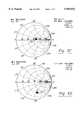
- FIGS. 6A-6Hare Smith Chart polar diagrams containing constant-resistance circles used to calculate data for Examples 1-8, respectively, in the specification.
- FIG. 1illustrates the prior art house arrest system 10 for a subject 12 incorporating a body worn transmitter 11 that communicates with a monitoring receiver 13 at the subject's residence 14 to determine when the subject is at the residence 14.
- the monitoring receiver 13can no longer receive signals from the body worn transmitter 11 on the subject 12.
- the monitoring receiver 13,using house power 16 or internal batteries, generates a phone call via the house telephone line 18 through the public switched telephone network 19 to the monitoring center 22 where the host computer 24 compares the allowable departure times to the time of the call from the monitoring receiver 13 at the subject's residence 14.
- Tamper detection in the prior art house arrest body worn transmitter 11can only report tampering signals to the subject 12 and the monitoring center 22 while the transmitter 11 is within range of the fixed location monitoring receiver 13. Therefore, while the subject 12 is away from his or her residence 14, activities are not reported that would trigger tampering signals or a violation of the subject's schedule or location.
- This prior art systemis subject to recording and retransmission known in the art as spoofing. This can either mask tampering with the transmission signal from the body worn transmitter 11 or make the transmitter 11 appear within range of the monitoring receiver when it is actually out of range.
- FIG. 2illustrates the twenty-four hour portable locating system 30 of this invention.
- the subject 12has an improved body worn transmitter 34 communicating with a portable monitoring receiver 36 carried by the subject 12 from his or her residence 14 to allowed locations such as his her workplace. Since there is no hard line phone number to verify the location of the monitoring receiver 36, radio signal triangulation from satellites 48 is performed in the portable monitoring receiver 36 allowing the monitoring receiver to determine its location. Location information for the subject 12 as well as transmitter 34 and portable monitoring receiver 36 health and status information is reported using a wireless network 38 and the public switched telephone network 19 to a central monitoring facility 42 where a subject's movements can be recorded for real-time or historical processing. When the subject is at his or her residence 14, the twenty-four hour portable monitoring receiver 36 connects directly to the public switched telephone network 19 using the subject's residential telephone line 18 connected to the battery charging stand 40.
- Law enforcement 46also can review the subject's current or recorded location data and can be dispatched to the subject's current location for apprehension of the subject.
- FIG. 3illustrates the twenty-four hour portable system body worn transmitter 34.
- the attaching strap 52is cut to fit the subject's ankle and is locked to the transmitter housing 54 by strap clamps 56 at each end of the attaching strap 52.
- the inner core 58 of the attaching strap 52is a corrosion resistant metal foil coated with a soft synthetic insulating material 60.
- the strap clamps 56secure the body worn transmitter 34 to the subject's body.
- the strap clamps 56electrically connect the attachment strap inner core 58 which acts as an antenna to the transmitter electronic circuit board 62 using embedded wires in the transmitter case between the tapped threads 65 for the strap clamp screws 63 and the transmitter electronics circuit board 62.
- the attachment strap antenna 58inductively couples the transmitted signal energy to the body of the subject.
- This methoduses the body of the subject as the antenna for the body worn transmitter.
- the body worn transmitter circuit board 62is powered by a replaceable battery 64.
- the body worn transmitter housing 54has a pressure sensitive switch 66 to determine when the cover 68 is removed.
- a waterproof gasket 61seals the cover 68 to the housing 54 of the body worn transmitter protecting the transmitter electronics.
- the cover 68when attached, covers the access to the strap clamp screws 63 forming tamper detection for access to strap clamps 56. Since the strap clamps 56 electrically connect the antenna 58 to the transmitter circuit board 62, removal of the strap clamps 56 will generate a tampering signal when the transmitter circuit board 62 loses connection to the antenna 58.
- the body worn transmitter circuit board 62When the body worn transmitter circuit board 62 is transmitting and the subject's body is functioning as an inductively coupled antenna through the inner core 58 of the attachment strap 52, radio power from the transmitter 34 is radiated by the antenna formed by the subject's body.
- the body of the subjectbecomes an antenna by the loop formed by the attachment strap antenna 58.
- This loopserves as a winding of a coil inducing transmitter power on the body of the subject. If the body worn transmitter 34 is removed from the body, the radio power from the transmitter 34 cannot be inductively transferred to the subject's body through the attaching strap antenna and is reflected back to the transmitter 34.
- the body worn bracelet circuitry shown in FIG. 4detects changes to the antenna reflected radio power or the voltage standing wave ratio (VSWR).
- VSWRvoltage standing wave ratio
- any portion of the body not immersed in an electrolyteserves as an antenna for the body worn transmitter. This permits the body worn transmitter to remain in contact with the monitoring receiver.
- the antennaBy embedding the transmitter antenna 58 in the attaching strap 52, the antenna must be altered in order to remove the body worn transmitter. Further, by measuring the reflected energy of the antenna coupling to the human body, any changes to the radio frequency characteristics of the antenna can be detected. Using a jumper wire to bridge a cut to the strap antenna or removing the transmitter from the body changes the antenna characteristics which will change the reflected energy of the antenna.
- Detecting changes to the reflected energy against a set threshold or changes to the ratio of transmitter power to the antenna reflected powerwill indicate tampering with the attachment strap.
- the ratio of transmitter power to reflected poweris commonly called reflection coefficient (10*log (power reflected/power coupled)).
- FIG. 4schematic illustrates the improved body worn transmitter tamper detection circuit for the portable locating system.
- a directional coupler 70is used to detect the reflected antenna 58 power or the ratio of power from the transmitter 34 to the reflected power from the antenna 58. In order for the ratio to be constant, the load impedance of the antenna 58 must remain constant. The portion of the power reflected from the antenna divided by the power sent from the antenna is known as the reflection coefficient.
- the directional coupler 70 reflected port 92is connected to a reflected power detector 76 that detects when the antennae reflected power is greater than a preset threshold 78 value.
- the directional coupler 70 reflected port 92 and the transmitter coupled port 90are connected to an analog comparator 94 that detects changes in the reflection coefficient.
- the forward powercan be measured at the couple port 90 resistor because the forward voltage and current are in phase with each other but the reflected voltage and current are 180 degrees out of phase and cancel.
- the reflected powercan be measured at the reflected port 92 resistor because the reflected voltage and current are in phase with each other but the forward voltage and current are 180 degrees out of phase and cancel.
- VSWRis the ratio of the peak additive voltage to the minimum subtractive voltage measured across the coupled port 90 and the reflected port 92.
- FIG. 5illustrates the functional block diagram of the tamper detection for body worn transmitters of this invention.
- the reflected power detector 100is an analog comparator that measures the reflected energy 102 sensed by the directional coupler 105 and compares it against a reference threshold 106 set at the desired reflected energy level when the antenna 58 is coupled to the body of the subject 12.
- the reflected power detector 100can also be a VSWR detector by replacing the threshold voltage 106 with the voltage measured at the coupled port 104 of the directional coupler 105.
- the body worn transmitter signalwill no longer be received by the portable tracking device since the subject's body no longer performs as the antenna exposed above the electrolyte solution.
- the portable monitoring receiver 36will report the lack of signal as a violation.
- the body worn transmitter 34sends strap tamper detection signal 125 as part of coded information 127 which is modulated on the transmitter's signal.
- the strap tamper detection logic 120will send a signal to reset the real time clock 145.
- the transmitter circuitrymatches the attachment strap antenna 58 to an approximate 50 ohm impedance using an adjustment 134.
- the body worn transmitter strap tampering signalcannot be defeated by jumpering a cut attachment strap antenna 58 since the jumper will change the impedance of the antenna thereby changing the reflected energy.
- the strap tamper detection logic 120cannot be bypassed inside the body worn transmitter housing 54 since the body worn transmitter 34 has case tamper detection 132 for an attempt to open the housing 54.
- the case tamper detection logic 132also will send a reset signal 147 to the real time clock 145.
- tamper defeating features of the body worn transmitterare an unique identification code 135 for each body worn transmitter, battery level reporting 140, a real-time clock 145 and data encryption 150.
- the portable monitoring receiver 36can be directed to accept the new body worn transmitter clock value from the central monitoring station 42, thereby allowing a remote reset of the tamper detection latch caused by resetting the real-time clock 145 in the body worn transmitter 34.
- the horizontal axis 205 of the Smith Chart 200represents normalized or constant resistance.
- the normal impedanceis at 50 ohms when inductively coupled to the body of the subject.
- the left half of the Smith Chartis high impedance and the right side is low impedance.
- the top half of the Smith Chartis positive reactance and inductive.
- the bottom of the Smith Chartis negative reactance and capacitive.
- FIG. 6Ameasurements were obtained from a connected (i.e., at both ends) 10 inch circumference attachment strap antenna 52 but not placed on the body of a subject.
- FIG. 6Bmeasurements were obtained from a connected 10 inch circumference attachment strap antenna 52 placed loosely on the body of the subject.
- the data points 210 from the table of measurementsdepict a measurable reduction in resistance and a measurable increase in inductance.
- FIG. 6C measurementswere obtained from a connected 10 inch circumference attachment strap antenna 52 placed closely to the body of the subject.
- the data points 220 from the table of measurementsdepict a measurable reduction in resistance, an increase in inductance and a transition to neutral reactance. These observations form a measurable trend from no coupling to loose coupling to close coupling to the subject's body.
- FIG. 6D measurementswere obtained from a fourteen inch circumference strap antenna 52 simulating an ideal severed attachment strap antenna 52 with a conductive jumper placed loosely on the subject's body.
- the data points 230 from the table of measurementsdepict a measurable difference in reactance, inductance and resistance to the data in FIG. 6B where the attachment strap antenna was placed loosely on the subject's body.
- FIG. 6Emeasurements wee obtained from a connected 14 inch circumference attachment strap antenna but not placed on the body of the subject.
- the data points 240 from the table of measurementsdepict that the reflected power characteristics (i.e., reactance and inductance) of a 14 inch and a 10 inch circumference antenna are similar, thereby making the measurements independent of the length of the attachment strap antenna.
- FIG. 6F measurementswere obtained from a connected 10 inch circumference attachment strap antenna immersed in salt water (strong electrolytic solution) but not placed on the body of the subject.
- the data points 250 from the table of measurementsdepict a measurable transition from negative to positive reactance and a lower impedance value than all other tests with the attachment strap antenna not immersed in an electrolyte.
- FIG. 6G measurementswere obtained from a connected 10 inch circumference attachment strap antenna immersed in tap water (weak electrolytic solution) but not placed on the body of the subject.
- the data points 260 from the table of measurementsestablishes that immersion of the attachment strap antenna in a weak electrolytic solution has similar results to immersion in a strong electrolytic solution from FIG. 6F.
- FIG. 6H measurementswere obtained from a connected 10 inch circumference attachment strap antenna immersed in tap water (weak electrolytic solution) coupled closely to the body of the subject.
- the data points 270 from the table of measurementsdepict that the immersion of the attachment strap antenna has similar results to immersion with the attachment strap antenna not placed on the body of the subject.
Landscapes
- Physics & Mathematics (AREA)
- General Physics & Mathematics (AREA)
- Business, Economics & Management (AREA)
- Emergency Management (AREA)
- Arrangements For Transmission Of Measured Signals (AREA)
Abstract
Description
______________________________________ Table of Frequency Measurements1: Mkr (MHz) Ohm Ohm______________________________________1: 406.00 66.11 -363.92: 410.00 55.28 -328.53: 414.00 50.19 -308.24: 418.00 49.96 -280.85: 422.00 47.6 -268.86: 426.00 41.5 -2527: 430.00 40.95 -237.18: 434.00 42.97 -226.5______________________________________
______________________________________ Table of Frequency Measurements1: Mkr (MHz) Ohm Ohm______________________________________1: 406.00 60.07 -61.872: 410.00 61.64 -59.793: 414.00 62.48 -59.444: 418.00 63.13 -57.975: 422.00 62.07 -57.456: 426.00 61.28 -56.647: 430.00 59.29 -55.658: 434.00 59.35 -53.77______________________________________
______________________________________ Table of Frequency Measurements1: Mkr (MHz) Ohm Ohm______________________________________1: 406.00 51.68 3.2152: 410.00 52.56 3.6683: 414.00 53.64 4.0434: 418.00 54.68 4.3535: 422.00 55.78 4.5656: 426.00 56.97 4.7467: 430.00 58.19 4.6558: 434.00 59.39 4.628______________________________________
______________________________________ Table of Frequency Measurements1: Mkr MHz Ohm Ohm______________________________________1: 406.00 32.23 -56.362: 410.00 32.72 -55.113: 414.00 31.92 -53.844: 418.00 31.76 -52.815 422.00 31.34 -51.496: 426.00 31 -50.277: 430.00 30.72 -48.598: 434.00 30.91 -48.08______________________________________
______________________________________ Table ofFrequency Measurements 1. Mkr MHz Ohm Ohm______________________________________1: 406.00 40.88 -205.22: 410.00 36.11 -197.33: 414.00 33.96 -190.44: 418.00 32.65 -186.45: 422.00 27.95 -176.26: 426.00 25.28 -171.97: 430.00 26.13 -164.88: 434.00 24.78 -160.2______________________________________
______________________________________ Table ofFrequency Measurements 1. Mkr MHz Ohm Ohm______________________________________1: 406.00 7.682 12.862: 410.00 7.508 12.553: 414.00 7.66 12.884: 418.00 7.847 12.95: 422.00 8.035 13.36: 426.00 8.045 12.87: 430.00 8.249 13.498: 434.00 8.384 13.19______________________________________
______________________________________ Table ofFrequency Measurements 1. Mkr MHz Ohm Ohm______________________________________1: 406.00 2.553 9.7562: 410.00 2.615 9.523: 414.00 2.679 10.494: 418.00 2.628 10.085: 422.00 2.82 116: 426.00 2.73 11.317: 430.00 2.901 11.978: 434.00 3.246 12.25______________________________________
______________________________________ Table ofFrequency Measurements 1. Mkr MHz Ohm Ohm______________________________________1: 406.00 4.135 8.9222: 410.00 4.349 8.9473. 414.00 4.325 9.6074: 418.00 4.489 9.4165: 422.00 4.599 10.026: 426.00 4.568 9.8617: 430.00 4.455 10.68: 434.00 4.388 10.55______________________________________
Claims (17)
Priority Applications (2)
| Application Number | Priority Date | Filing Date | Title |
|---|---|---|---|
| US08/863,158US5959533A (en) | 1997-05-27 | 1997-05-27 | Tamper detection for body worn transmitter |
| US09/330,858US6405213B1 (en) | 1997-05-27 | 1999-06-11 | System to correlate crime incidents with a subject's location using crime incident data and a subject location recording device |
Applications Claiming Priority (1)
| Application Number | Priority Date | Filing Date | Title |
|---|---|---|---|
| US08/863,158US5959533A (en) | 1997-05-27 | 1997-05-27 | Tamper detection for body worn transmitter |
Related Child Applications (1)
| Application Number | Title | Priority Date | Filing Date |
|---|---|---|---|
| US09/181,244Continuation-In-PartUS6014080A (en) | 1997-05-27 | 1998-10-28 | Body worn active and passive tracking device |
Publications (1)
| Publication Number | Publication Date |
|---|---|
| US5959533Atrue US5959533A (en) | 1999-09-28 |
Family
ID=25340414
Family Applications (1)
| Application Number | Title | Priority Date | Filing Date |
|---|---|---|---|
| US08/863,158Expired - LifetimeUS5959533A (en) | 1997-05-27 | 1997-05-27 | Tamper detection for body worn transmitter |
Country Status (1)
| Country | Link |
|---|---|
| US (1) | US5959533A (en) |
Cited By (82)
| Publication number | Priority date | Publication date | Assignee | Title |
|---|---|---|---|---|
| WO2000007155A3 (en)* | 1998-07-31 | 2000-09-28 | Beryl E Pitzer | Personal monitoring system |
| WO2001026067A1 (en)* | 1999-10-05 | 2001-04-12 | Bi Incorporated | Authentication techniques in a monitoring system |
| US6268797B1 (en)* | 2000-03-15 | 2001-07-31 | Detection Systems, Inc. | Integrated portable tracking signal and access authorization signal generator |
| WO2001084274A3 (en)* | 2000-05-01 | 2002-02-21 | Kline & Walker Llc | Personal pfn systems for tracking and locating |
| WO2002054092A1 (en)* | 2000-12-28 | 2002-07-11 | Bird Electronic Corporation | Vswr monitor and alarm |
| US20020152604A1 (en)* | 2001-04-23 | 2002-10-24 | Debraal John Charles | Method and system for forming electrically conductive pathways |
| US6624752B2 (en)* | 1999-11-15 | 2003-09-23 | Bluetags A/S | Object detection system |
| US20030222781A1 (en)* | 2002-06-03 | 2003-12-04 | Pro Tech Monitoring, Inc. | House arrest tracker system |
| US20040012518A1 (en)* | 1994-10-12 | 2004-01-22 | Paul Mohan | Tracking system using miniaturized concealable communications module |
| US20040030226A1 (en)* | 1999-12-17 | 2004-02-12 | Quy Roger J. | Method and apparatus for health and disease management combining patient data monitoring with wireless internet connectivity |
| US6703936B2 (en) | 2001-09-28 | 2004-03-09 | Veridian Engineering, Inc. | System and method for tracking movement of individuals |
| US20040046667A1 (en)* | 2002-05-14 | 2004-03-11 | Copley Shaun Michael | Personal tracking device |
| US20040054900A1 (en)* | 2002-09-12 | 2004-03-18 | Duanfeng He | System and method for encrypted communications between electronic devices |
| US6774797B2 (en) | 2002-05-10 | 2004-08-10 | On Guard Plus Limited | Wireless tag and monitoring center system for tracking the activities of individuals |
| US6779246B2 (en) | 2001-04-23 | 2004-08-24 | Appleton Papers Inc. | Method and system for forming RF reflective pathways |
| US20040174264A1 (en)* | 2003-03-05 | 2004-09-09 | Dmatek Ltd. | Monitoring and tracking network |
| US20040183673A1 (en)* | 2003-01-31 | 2004-09-23 | Nageli Hans Peter | Portable detachable self-contained tracking unit for two-way satellite communication with a central server |
| US6836212B2 (en)* | 2002-10-10 | 2004-12-28 | Motorola, Inc. | Method and apparatus for reducing the likelihood of losing a portable electronic device |
| US20050068169A1 (en)* | 2002-05-14 | 2005-03-31 | Copley Shuan Michael | Personal tracking device |
| US20050228245A1 (en)* | 1999-12-17 | 2005-10-13 | Q-Tec Systems Llc | Method and apparatus for health and disease management combining patient data monitoring with wireless internet connectivity |
| USRE38838E1 (en) | 1997-09-10 | 2005-10-18 | Taylor Jr John E | Monitoring system |
| US20050278044A1 (en)* | 2004-06-14 | 2005-12-15 | Yue Chen | Method and system for codec with polyringer |
| US6976958B2 (en) | 2000-12-15 | 2005-12-20 | Q-Tec Systems Llc | Method and apparatus for health and disease management combining patient data monitoring with wireless internet connectivity |
| US7098792B1 (en) | 2003-05-14 | 2006-08-29 | Rf Technologies, Inc. | Tamper proof system and method |
| USD535205S1 (en) | 2005-07-21 | 2007-01-16 | Ohio House Monitoring Systems, Inc. | Monitoring bracelet |
| US7242307B1 (en) | 2003-10-20 | 2007-07-10 | Cognetive Systems Incorporated | System for monitoring hygiene appliances |
| US20070171047A1 (en)* | 2006-01-25 | 2007-07-26 | Goodman Gregory D | Device and system for locating and providing status of persons, animals or objects |
| WO2007125319A1 (en)* | 2006-04-26 | 2007-11-08 | Active Tagging Limited | Rfid receiver with distributed intelligence |
| US20070285258A1 (en)* | 2006-06-13 | 2007-12-13 | Hartman Kevin L | Device for Tethering a Person Wirelessly with a Cellular Telephone |
| USD559138S1 (en) | 2006-06-30 | 2008-01-08 | Cothron Candace R | Security alert pendant with GPS unit |
| US20080088437A1 (en)* | 2005-05-06 | 2008-04-17 | Omnilink Systems, Inc. | System and method for monitoring alarms and responding to the movement of individuals and assets |
| US20080108370A1 (en)* | 2005-04-06 | 2008-05-08 | Steve Aninye | System and Method for Tracking, Monitoring, Collecting, Reporting and Communicating with the Movement of Individuals |
| US7423533B1 (en) | 2004-10-19 | 2008-09-09 | Cognetive Systems, Incorporated | System for monitoring and recording cross-contamination events |
| USD578918S1 (en) | 2007-05-01 | 2008-10-21 | Omnilink Systems, Inc. | Offender monitor |
| US20090207050A1 (en)* | 2008-02-14 | 2009-08-20 | Claude Arpin | Asset recovery system |
| US20090212957A1 (en)* | 2008-02-22 | 2009-08-27 | New Wave Technology Inc. | Portable monitoring apparatus with over the air programming and sampling volume collection cavity |
| US7598854B2 (en) | 2005-03-01 | 2009-10-06 | Chon Meng Wong | System and method for creating a proximity map of plurality of living beings and objects |
| US7619513B2 (en) | 2003-10-03 | 2009-11-17 | Satellite Tracking Of People Llc | System and method for tracking movement of individuals |
| US20100090826A1 (en)* | 2008-10-10 | 2010-04-15 | Brian Sean Moran | Technique for Detecting Tracking Device Tampering Using An Auxiliary Device |
| US20100120585A1 (en)* | 2004-02-06 | 2010-05-13 | Q-Tec Systems Llc | Method and apparatus for exercise monitoring combining exercise monitoring and visual data with wireless internet connectivity |
| US20100123589A1 (en)* | 2008-11-14 | 2010-05-20 | Bi Incorporated | Systems and Methods for Adaptive Monitoring of Physical Movement |
| US7737841B2 (en) | 2006-07-14 | 2010-06-15 | Remotemdx | Alarm and alarm management system for remote tracking devices |
| US20100153374A1 (en)* | 2006-04-07 | 2010-06-17 | Cognetive Systems Incorporated | System for Monitoring and Recording Hand Hygiene Performance |
| US7804412B2 (en) | 2005-08-10 | 2010-09-28 | Securealert, Inc. | Remote tracking and communication device |
| US20100309002A1 (en)* | 2009-06-09 | 2010-12-09 | Duvall William R | Proximity monitoring and locating system |
| GB2473067A (en)* | 2009-09-01 | 2011-03-02 | Guidance Monitoring Ltd | Proximity sensor for detecting an attempt to disable a monitoring tag or portable GPS tracking device |
| US20110050446A1 (en)* | 2009-09-01 | 2011-03-03 | Guidance IP, Ltd. | Proximity sensors |
| US7936262B2 (en) | 2006-07-14 | 2011-05-03 | Securealert, Inc. | Remote tracking system with a dedicated monitoring center |
| US20110109461A1 (en)* | 2009-11-06 | 2011-05-12 | Steve Aninye | Tamper detection system for use with personal monitoring devices |
| US20110133928A1 (en)* | 2009-12-03 | 2011-06-09 | Bi Incorporated | Systems and Methods for Variable Collision Avoidance |
| US20110133937A1 (en)* | 2009-12-03 | 2011-06-09 | Bi Incorporated | Systems and Methods for Disrupting Criminal Activity |
| US20110154887A1 (en)* | 2007-03-06 | 2011-06-30 | Bi Incorporated | Transdermal Portable Alcohol Monitor and Methods for Using Such |
| GB2477917A (en)* | 2010-02-15 | 2011-08-24 | Guidance Ip Ltd | Proximity sensor for detecting an attempt to disable a monitoring tag or portable GPS tracking device |
| US20110309930A1 (en)* | 2009-02-16 | 2011-12-22 | Fm S.R.L. | Method and system for managing geographically distributed resources |
| US8115621B2 (en) | 2007-05-01 | 2012-02-14 | Yoganand Rajala | Device for tracking the movement of individuals or objects |
| US8232876B2 (en) | 2008-03-07 | 2012-07-31 | Securealert, Inc. | System and method for monitoring individuals using a beacon and intelligent remote tracking device |
| US8410926B1 (en) | 2010-05-07 | 2013-04-02 | Rf Technologies, Inc. | Alarm for security tag |
| USRE44275E1 (en)* | 2000-11-06 | 2013-06-11 | Loran Technologies, Inc. | Electronic vehicle product and personnel monitoring |
| US20130165157A1 (en)* | 2011-12-24 | 2013-06-27 | Michael MAPES | Secure Witness or Criminal Participant Location or Position and Time Recording Information Apparatus, Systemts and Methods |
| US8489113B2 (en) | 2010-02-09 | 2013-07-16 | Omnilink Systems, Inc. | Method and system for tracking, monitoring and/or charging tracking devices including wireless energy transfer features |
| US8514070B2 (en) | 2010-04-07 | 2013-08-20 | Securealert, Inc. | Tracking device incorporating enhanced security mounting strap |
| US8560557B1 (en) | 2011-12-14 | 2013-10-15 | Corrisoft, LLC | Method and system of progress monitoring |
| US8657744B2 (en) | 2009-03-23 | 2014-02-25 | Bi Incorporated | Systems and methods for transdermal secretion detection |
| US8682356B2 (en) | 2011-12-22 | 2014-03-25 | Earthsweep Llc | Method and system of electronic monitoring |
| US8797210B2 (en) | 2006-07-14 | 2014-08-05 | Securealert, Inc. | Remote tracking device and a system and method for two-way voice communication between the device and a monitoring center |
| US20140253322A1 (en)* | 2013-03-11 | 2014-09-11 | SDC Inc. | System, Method, and Apparatus for Detecting Wireless Devices |
| US8862152B1 (en) | 2012-11-02 | 2014-10-14 | Alcohol Monitoring Systems, Inc. | Two-piece system and method for electronic management of offenders based on real-time risk profiles |
| US9024750B2 (en) | 2013-07-25 | 2015-05-05 | 3M Innovative Properties Company | Method to calibrate a fiber optic strap on a body worn device |
| US20150194026A1 (en)* | 2009-12-30 | 2015-07-09 | Glenn C. Johnson | Object locator system and method |
| GB2525293A (en)* | 2014-02-27 | 2015-10-21 | Fidelis Technology Ltd | Transmission of information in a transaction system |
| US9215578B2 (en) | 2012-01-27 | 2015-12-15 | Omnilink Systems, Inc. | Monitoring systems and methods |
| US9355548B2 (en) | 2009-12-03 | 2016-05-31 | Bi Incorporated | Systems and methods for contact avoidance |
| US9521513B2 (en) | 2014-10-21 | 2016-12-13 | Earthsweep Llc | Method and system of zone suspension in electronic monitoring |
| US9882674B1 (en) | 2017-07-02 | 2018-01-30 | Fidelity Engineering Group, Inc. | System, method, and apparatus for detecting and jamming wireless devices |
| US10082568B1 (en)* | 2013-01-22 | 2018-09-25 | Hoyt Mac Layson, JR. | Detailed description |
| WO2020094588A1 (en)* | 2018-11-05 | 2020-05-14 | Andrew Wireless Systems Gmbh | Methods and apparatuses for reflection measurements |
| US11308748B2 (en)* | 2019-05-15 | 2022-04-19 | Endur ID, Inc. | Flexible identification band with cut detection |
| US11622314B2 (en) | 2019-12-30 | 2023-04-04 | Detection Innovation Group, Inc. | System, method, and apparatus for detecting and preventing wireless connections |
| US11665507B2 (en) | 2020-09-15 | 2023-05-30 | Bi Incorporated | Systems and methods for intercept directing in a monitoring system |
| US11701007B2 (en) | 2020-08-28 | 2023-07-18 | Bi Incorporated | Systems and methods for biometric tamper detection |
| US12307876B2 (en) | 2023-07-24 | 2025-05-20 | Detection Innovation Group, Inc. | System, method, and apparatus for detecting and alerting of inmate usage of cafeteria |
| USD1080443S1 (en) | 2022-08-12 | 2025-06-24 | Endur ID, Inc. | Clasp |
Citations (11)
| Publication number | Priority date | Publication date | Assignee | Title |
|---|---|---|---|---|
| US4812823A (en)* | 1987-04-13 | 1989-03-14 | Bi Incorporated | Locked transmitter tag assembly and method of lockably attaching same to object |
| US4952928A (en)* | 1988-08-29 | 1990-08-28 | B. I. Incorporated | Adaptable electronic monitoring and identification system |
| US4980671A (en)* | 1989-04-26 | 1990-12-25 | Guardian Technologies, Inc. | Remote confinement system with timed tamper signal reset |
| US5014040A (en)* | 1988-10-14 | 1991-05-07 | Instantel Inc. | Personal locator transmitter |
| US5204670A (en)* | 1988-08-29 | 1993-04-20 | B. I. Incorporated | Adaptable electric monitoring and identification system |
| US5298884A (en)* | 1992-10-16 | 1994-03-29 | Bi Incorporated | Tamper detection circuit and method for use with wearable transmitter tag |
| US5461390A (en)* | 1994-05-27 | 1995-10-24 | At&T Ipm Corp. | Locator device useful for house arrest and stalker detection |
| US5504474A (en)* | 1994-07-18 | 1996-04-02 | Elmo Tech Ltd. | Tag for electronic personnel monitoring |
| US5523740A (en)* | 1995-04-24 | 1996-06-04 | Detection Systems, Inc. | Wearable transmitter assembly |
| US5650766A (en)* | 1995-04-24 | 1997-07-22 | Detection Systems, Inc. | Wearable transmitter with optical tamper detection |
| US5742233A (en)* | 1997-01-21 | 1998-04-21 | Hoffman Resources, Llc | Personal security and tracking system |
- 1997
- 1997-05-27USUS08/863,158patent/US5959533A/ennot_activeExpired - Lifetime
Patent Citations (11)
| Publication number | Priority date | Publication date | Assignee | Title |
|---|---|---|---|---|
| US4812823A (en)* | 1987-04-13 | 1989-03-14 | Bi Incorporated | Locked transmitter tag assembly and method of lockably attaching same to object |
| US4952928A (en)* | 1988-08-29 | 1990-08-28 | B. I. Incorporated | Adaptable electronic monitoring and identification system |
| US5204670A (en)* | 1988-08-29 | 1993-04-20 | B. I. Incorporated | Adaptable electric monitoring and identification system |
| US5014040A (en)* | 1988-10-14 | 1991-05-07 | Instantel Inc. | Personal locator transmitter |
| US4980671A (en)* | 1989-04-26 | 1990-12-25 | Guardian Technologies, Inc. | Remote confinement system with timed tamper signal reset |
| US5298884A (en)* | 1992-10-16 | 1994-03-29 | Bi Incorporated | Tamper detection circuit and method for use with wearable transmitter tag |
| US5461390A (en)* | 1994-05-27 | 1995-10-24 | At&T Ipm Corp. | Locator device useful for house arrest and stalker detection |
| US5504474A (en)* | 1994-07-18 | 1996-04-02 | Elmo Tech Ltd. | Tag for electronic personnel monitoring |
| US5523740A (en)* | 1995-04-24 | 1996-06-04 | Detection Systems, Inc. | Wearable transmitter assembly |
| US5650766A (en)* | 1995-04-24 | 1997-07-22 | Detection Systems, Inc. | Wearable transmitter with optical tamper detection |
| US5742233A (en)* | 1997-01-21 | 1998-04-21 | Hoffman Resources, Llc | Personal security and tracking system |
Cited By (141)
| Publication number | Priority date | Publication date | Assignee | Title |
|---|---|---|---|---|
| US20040012518A1 (en)* | 1994-10-12 | 2004-01-22 | Paul Mohan | Tracking system using miniaturized concealable communications module |
| USRE44085E1 (en) | 1997-09-10 | 2013-03-19 | Satellite Tracking of People LLP | Tracking system for locational tracking of monitored persons |
| USRE38838E1 (en) | 1997-09-10 | 2005-10-18 | Taylor Jr John E | Monitoring system |
| USRE42671E1 (en) | 1997-09-10 | 2011-09-06 | Michelle Enterprises, Llc | Tracking system for locational tracking of monitored persons |
| USRE39909E1 (en) | 1997-09-10 | 2007-11-06 | Michelle Enterprises, Llc | Tracking system for locational tracking of monitored persons |
| WO2000007155A3 (en)* | 1998-07-31 | 2000-09-28 | Beryl E Pitzer | Personal monitoring system |
| WO2001026067A1 (en)* | 1999-10-05 | 2001-04-12 | Bi Incorporated | Authentication techniques in a monitoring system |
| AU778793C (en)* | 1999-10-05 | 2006-03-02 | Bi Incorporated | Authentication techniques in a monitoring system |
| US6844816B1 (en) | 1999-10-05 | 2005-01-18 | Bi Incorporated | Authentication techniques in a monitoring system |
| AU778793B2 (en)* | 1999-10-05 | 2004-12-23 | Bi Incorporated | Authentication techniques in a monitoring system |
| US6624752B2 (en)* | 1999-11-15 | 2003-09-23 | Bluetags A/S | Object detection system |
| US20040030226A1 (en)* | 1999-12-17 | 2004-02-12 | Quy Roger J. | Method and apparatus for health and disease management combining patient data monitoring with wireless internet connectivity |
| US6936007B2 (en)* | 1999-12-17 | 2005-08-30 | Q-Tec Systems Llp | Method and apparatus for health and disease management combining patient data monitoring with wireless internet connectivity |
| US20090069643A1 (en)* | 1999-12-17 | 2009-03-12 | Q-Tec Systems Llc | Method and apparatus for health and disease management combining patient data monitoring with wireless internet connectivity |
| US7156808B2 (en) | 1999-12-17 | 2007-01-02 | Q-Tec Systems Llc | Method and apparatus for health and disease management combining patient data monitoring with wireless internet connectivity |
| US8277377B2 (en) | 1999-12-17 | 2012-10-02 | Q-Tec Systems Llc | Method and apparatus for monitoring exercise with wireless internet connectivity |
| US20050250995A1 (en)* | 1999-12-17 | 2005-11-10 | Quy Roger J | Method and apparatus for health and disease management combining patient data monitoring with wireless Internet connectivity |
| US20070293733A1 (en)* | 1999-12-17 | 2007-12-20 | Quy Roger J | Method and apparatus for health and disease management combining patient data monitoring with wireless internet connectivity |
| US20050228245A1 (en)* | 1999-12-17 | 2005-10-13 | Q-Tec Systems Llc | Method and apparatus for health and disease management combining patient data monitoring with wireless internet connectivity |
| US20070232942A1 (en)* | 1999-12-17 | 2007-10-04 | Quy Roger J | Method and apparatus for health and disease management combining patient data monitoring with wireless internet connectivity |
| US7156809B2 (en) | 1999-12-17 | 2007-01-02 | Q-Tec Systems Llc | Method and apparatus for health and disease management combining patient data monitoring with wireless internet connectivity |
| US6268797B1 (en)* | 2000-03-15 | 2001-07-31 | Detection Systems, Inc. | Integrated portable tracking signal and access authorization signal generator |
| WO2001084274A3 (en)* | 2000-05-01 | 2002-02-21 | Kline & Walker Llc | Personal pfn systems for tracking and locating |
| USRE44275E1 (en)* | 2000-11-06 | 2013-06-11 | Loran Technologies, Inc. | Electronic vehicle product and personnel monitoring |
| US6976958B2 (en) | 2000-12-15 | 2005-12-20 | Q-Tec Systems Llc | Method and apparatus for health and disease management combining patient data monitoring with wireless internet connectivity |
| WO2002054092A1 (en)* | 2000-12-28 | 2002-07-11 | Bird Electronic Corporation | Vswr monitor and alarm |
| US6779246B2 (en) | 2001-04-23 | 2004-08-24 | Appleton Papers Inc. | Method and system for forming RF reflective pathways |
| US20050151700A1 (en)* | 2001-04-23 | 2005-07-14 | Appleton Papers Inc. | Method and system for forming electrically conductive pathways |
| US6892441B2 (en) | 2001-04-23 | 2005-05-17 | Appleton Papers Inc. | Method for forming electrically conductive pathways |
| US20020152604A1 (en)* | 2001-04-23 | 2002-10-24 | Debraal John Charles | Method and system for forming electrically conductive pathways |
| US20050099308A1 (en)* | 2001-09-28 | 2005-05-12 | Hill Maurice L. | System and method for tracking movement of individuals |
| US6992582B2 (en) | 2001-09-28 | 2006-01-31 | Satellite Tracking Of People Llc | System and method for tracking movement of individuals |
| US6703936B2 (en) | 2001-09-28 | 2004-03-09 | Veridian Engineering, Inc. | System and method for tracking movement of individuals |
| US6774797B2 (en) | 2002-05-10 | 2004-08-10 | On Guard Plus Limited | Wireless tag and monitoring center system for tracking the activities of individuals |
| US20040046667A1 (en)* | 2002-05-14 | 2004-03-11 | Copley Shaun Michael | Personal tracking device |
| US6972684B2 (en) | 2002-05-14 | 2005-12-06 | Celltrack, Llc | Personal tracking device |
| US7015817B2 (en) | 2002-05-14 | 2006-03-21 | Shuan Michael Copley | Personal tracking device |
| US20050068169A1 (en)* | 2002-05-14 | 2005-03-31 | Copley Shuan Michael | Personal tracking device |
| US6774799B2 (en)* | 2002-06-03 | 2004-08-10 | Pro Tech Monitoring, Inc. | House arrest tracker system |
| US20030222781A1 (en)* | 2002-06-03 | 2003-12-04 | Pro Tech Monitoring, Inc. | House arrest tracker system |
| US6957333B2 (en)* | 2002-09-12 | 2005-10-18 | Symbol Technologies, Inc. | System and method for encrypted communications between electronic devices |
| WO2004025418A3 (en)* | 2002-09-12 | 2004-06-17 | Symbol Technologies Inc | System and method for encrypted communications between electronic devices |
| US20040054900A1 (en)* | 2002-09-12 | 2004-03-18 | Duanfeng He | System and method for encrypted communications between electronic devices |
| US6836212B2 (en)* | 2002-10-10 | 2004-12-28 | Motorola, Inc. | Method and apparatus for reducing the likelihood of losing a portable electronic device |
| US20040183673A1 (en)* | 2003-01-31 | 2004-09-23 | Nageli Hans Peter | Portable detachable self-contained tracking unit for two-way satellite communication with a central server |
| US20040174264A1 (en)* | 2003-03-05 | 2004-09-09 | Dmatek Ltd. | Monitoring and tracking network |
| US6998985B2 (en) | 2003-03-05 | 2006-02-14 | Dmatek, Ltd. | Monitoring and tracking network |
| US7098792B1 (en) | 2003-05-14 | 2006-08-29 | Rf Technologies, Inc. | Tamper proof system and method |
| US7619513B2 (en) | 2003-10-03 | 2009-11-17 | Satellite Tracking Of People Llc | System and method for tracking movement of individuals |
| US7242307B1 (en) | 2003-10-20 | 2007-07-10 | Cognetive Systems Incorporated | System for monitoring hygiene appliances |
| US9272183B2 (en) | 2003-12-11 | 2016-03-01 | Q-Tec Systems Llc | Method and apparatus for exercise monitoring combining exercise monitoring and visual data with wireless wearable devices |
| US20100120585A1 (en)* | 2004-02-06 | 2010-05-13 | Q-Tec Systems Llc | Method and apparatus for exercise monitoring combining exercise monitoring and visual data with wireless internet connectivity |
| US9943723B2 (en) | 2004-02-06 | 2018-04-17 | Koninklijke Philips N.V. | Method and apparatus for exercise monitoring combining exercise monitoring and visual data with wireless wearable devices |
| US8712510B2 (en) | 2004-02-06 | 2014-04-29 | Q-Tec Systems Llc | Method and apparatus for exercise monitoring combining exercise monitoring and visual data with wireless internet connectivity |
| US10632342B2 (en) | 2004-02-06 | 2020-04-28 | Koninklijke Philips N.V. | Method and apparatus for exercise monitoring combining exercise monitoring and visual data with wireless devices |
| US20050278044A1 (en)* | 2004-06-14 | 2005-12-15 | Yue Chen | Method and system for codec with polyringer |
| US7423533B1 (en) | 2004-10-19 | 2008-09-09 | Cognetive Systems, Incorporated | System for monitoring and recording cross-contamination events |
| US7598854B2 (en) | 2005-03-01 | 2009-10-06 | Chon Meng Wong | System and method for creating a proximity map of plurality of living beings and objects |
| US8405503B2 (en) | 2005-03-01 | 2013-03-26 | Chon Meng Wong | System and method for creating a proximity map of living beings and objects |
| US20100097209A1 (en)* | 2005-03-01 | 2010-04-22 | Chon Meng Wong | System and method for creating a proximity map of living beings and objects |
| US20080108370A1 (en)* | 2005-04-06 | 2008-05-08 | Steve Aninye | System and Method for Tracking, Monitoring, Collecting, Reporting and Communicating with the Movement of Individuals |
| US8831627B2 (en) | 2005-04-06 | 2014-09-09 | Omnilink Systems, Inc. | System and method for tracking, monitoring, collecting, reporting and communicating with the movement of individuals |
| US8547222B2 (en) | 2005-05-06 | 2013-10-01 | Omnilink Systems, Inc. | System and method of tracking the movement of individuals and assets |
| US20090174550A1 (en)* | 2005-05-06 | 2009-07-09 | Omnilink Systems, Inc. | System and method for monitoring alarms and responding to the movement of individuals and assets |
| US7518500B2 (en) | 2005-05-06 | 2009-04-14 | Omnilink Systems, Inc. | System and method for monitoring alarms and responding to the movement of individuals and assets |
| US20080088437A1 (en)* | 2005-05-06 | 2008-04-17 | Omnilink Systems, Inc. | System and method for monitoring alarms and responding to the movement of individuals and assets |
| US7864047B2 (en) | 2005-05-06 | 2011-01-04 | Omnilink Systems, Inc. | System and method for monitoring alarms and responding to the movement of individuals and assets |
| US9373241B2 (en) | 2005-05-06 | 2016-06-21 | Omnilink Systems, Inc. | System and method for monitoring a wireless tracking device |
| USD535205S1 (en) | 2005-07-21 | 2007-01-16 | Ohio House Monitoring Systems, Inc. | Monitoring bracelet |
| US8031077B2 (en) | 2005-08-10 | 2011-10-04 | Securealert, Inc. | Remote tracking and communication device |
| US7804412B2 (en) | 2005-08-10 | 2010-09-28 | Securealert, Inc. | Remote tracking and communication device |
| US20070171047A1 (en)* | 2006-01-25 | 2007-07-26 | Goodman Gregory D | Device and system for locating and providing status of persons, animals or objects |
| US7855651B2 (en) | 2006-04-07 | 2010-12-21 | Cognetive Systems Incorporated | System for monitoring and recording hand hygiene performance |
| US8094029B2 (en) | 2006-04-07 | 2012-01-10 | Cognetive Systems Incorporated | System for monitoring and recording hand hygiene performance |
| US20110093313A1 (en)* | 2006-04-07 | 2011-04-21 | Cognetive Systems Incorporated | System for Monitoring and Recording Hand Hygiene Performance |
| US20100153374A1 (en)* | 2006-04-07 | 2010-06-17 | Cognetive Systems Incorporated | System for Monitoring and Recording Hand Hygiene Performance |
| WO2007125319A1 (en)* | 2006-04-26 | 2007-11-08 | Active Tagging Limited | Rfid receiver with distributed intelligence |
| US20070285258A1 (en)* | 2006-06-13 | 2007-12-13 | Hartman Kevin L | Device for Tethering a Person Wirelessly with a Cellular Telephone |
| US7382268B2 (en) | 2006-06-13 | 2008-06-03 | Hartman Kevin L | Device and method for tethering a person wirelessly with a cellular telephone |
| USD559138S1 (en) | 2006-06-30 | 2008-01-08 | Cothron Candace R | Security alert pendant with GPS unit |
| US8013736B2 (en) | 2006-07-14 | 2011-09-06 | Securealert, Inc. | Alarm and alarm management system for remote tracking devices |
| US7737841B2 (en) | 2006-07-14 | 2010-06-15 | Remotemdx | Alarm and alarm management system for remote tracking devices |
| US7936262B2 (en) | 2006-07-14 | 2011-05-03 | Securealert, Inc. | Remote tracking system with a dedicated monitoring center |
| US8797210B2 (en) | 2006-07-14 | 2014-08-05 | Securealert, Inc. | Remote tracking device and a system and method for two-way voice communication between the device and a monitoring center |
| US20110154887A1 (en)* | 2007-03-06 | 2011-06-30 | Bi Incorporated | Transdermal Portable Alcohol Monitor and Methods for Using Such |
| US8115621B2 (en) | 2007-05-01 | 2012-02-14 | Yoganand Rajala | Device for tracking the movement of individuals or objects |
| USD578918S1 (en) | 2007-05-01 | 2008-10-21 | Omnilink Systems, Inc. | Offender monitor |
| US8013735B2 (en) | 2008-02-14 | 2011-09-06 | Lojack Operating Company, Lp | Asset recovery system |
| US20090207050A1 (en)* | 2008-02-14 | 2009-08-20 | Claude Arpin | Asset recovery system |
| US7750815B2 (en) | 2008-02-22 | 2010-07-06 | Quantum Electronics Ltd. | Portable monitoring apparatus with over the air programming and sampling volume collection cavity |
| US20090212957A1 (en)* | 2008-02-22 | 2009-08-27 | New Wave Technology Inc. | Portable monitoring apparatus with over the air programming and sampling volume collection cavity |
| US8232876B2 (en) | 2008-03-07 | 2012-07-31 | Securealert, Inc. | System and method for monitoring individuals using a beacon and intelligent remote tracking device |
| US8395513B2 (en) | 2008-10-10 | 2013-03-12 | Satellite Tracking of People LLP | Technique for detecting tracking device tampering using an auxiliary device |
| US20100090826A1 (en)* | 2008-10-10 | 2010-04-15 | Brian Sean Moran | Technique for Detecting Tracking Device Tampering Using An Auxiliary Device |
| US8493219B2 (en) | 2008-11-14 | 2013-07-23 | Bi Incorporated | Systems and methods for adaptive monitoring and tracking of a target having a learning period |
| US20100123589A1 (en)* | 2008-11-14 | 2010-05-20 | Bi Incorporated | Systems and Methods for Adaptive Monitoring of Physical Movement |
| US8907784B2 (en)* | 2009-02-16 | 2014-12-09 | Fm S.R.L. | Method and system for managing geographically distributed resources |
| US20110309930A1 (en)* | 2009-02-16 | 2011-12-22 | Fm S.R.L. | Method and system for managing geographically distributed resources |
| US8657744B2 (en) | 2009-03-23 | 2014-02-25 | Bi Incorporated | Systems and methods for transdermal secretion detection |
| US8169328B2 (en) | 2009-06-09 | 2012-05-01 | Lojack Operating Company, Lp | Proximity monitoring and locating system |
| US20100309002A1 (en)* | 2009-06-09 | 2010-12-09 | Duvall William R | Proximity monitoring and locating system |
| GB2473067B (en)* | 2009-09-01 | 2011-08-17 | Guidance Monitoring Ltd | Proximity sensors |
| US20110050446A1 (en)* | 2009-09-01 | 2011-03-03 | Guidance IP, Ltd. | Proximity sensors |
| GB2473067A (en)* | 2009-09-01 | 2011-03-02 | Guidance Monitoring Ltd | Proximity sensor for detecting an attempt to disable a monitoring tag or portable GPS tracking device |
| US8629771B2 (en) | 2009-09-01 | 2014-01-14 | John Anderson | Proximity sensors |
| US20110109461A1 (en)* | 2009-11-06 | 2011-05-12 | Steve Aninye | Tamper detection system for use with personal monitoring devices |
| US8629776B2 (en) | 2009-12-03 | 2014-01-14 | Bi Incorporated | Systems and methods for disrupting criminal activity |
| US8576065B2 (en) | 2009-12-03 | 2013-11-05 | Bi Incorporated | Systems and methods for variable collision avoidance |
| US9355548B2 (en) | 2009-12-03 | 2016-05-31 | Bi Incorporated | Systems and methods for contact avoidance |
| US20110133937A1 (en)* | 2009-12-03 | 2011-06-09 | Bi Incorporated | Systems and Methods for Disrupting Criminal Activity |
| US20110133928A1 (en)* | 2009-12-03 | 2011-06-09 | Bi Incorporated | Systems and Methods for Variable Collision Avoidance |
| US20150194026A1 (en)* | 2009-12-30 | 2015-07-09 | Glenn C. Johnson | Object locator system and method |
| US8489113B2 (en) | 2010-02-09 | 2013-07-16 | Omnilink Systems, Inc. | Method and system for tracking, monitoring and/or charging tracking devices including wireless energy transfer features |
| GB2477917B (en)* | 2010-02-15 | 2012-02-22 | Guidance Ip Ltd | Proximity sensors |
| GB2477917A (en)* | 2010-02-15 | 2011-08-24 | Guidance Ip Ltd | Proximity sensor for detecting an attempt to disable a monitoring tag or portable GPS tracking device |
| US8514070B2 (en) | 2010-04-07 | 2013-08-20 | Securealert, Inc. | Tracking device incorporating enhanced security mounting strap |
| US9129504B2 (en) | 2010-04-07 | 2015-09-08 | Securealert, Inc. | Tracking device incorporating cuff with cut resistant materials |
| US8410926B1 (en) | 2010-05-07 | 2013-04-02 | Rf Technologies, Inc. | Alarm for security tag |
| US8560557B1 (en) | 2011-12-14 | 2013-10-15 | Corrisoft, LLC | Method and system of progress monitoring |
| US8682356B2 (en) | 2011-12-22 | 2014-03-25 | Earthsweep Llc | Method and system of electronic monitoring |
| US8971932B2 (en)* | 2011-12-24 | 2015-03-03 | Secure Sigint, LLC | Secure witness or criminal participant location or position and time recording information apparatus, systemts and methods |
| US20130165157A1 (en)* | 2011-12-24 | 2013-06-27 | Michael MAPES | Secure Witness or Criminal Participant Location or Position and Time Recording Information Apparatus, Systemts and Methods |
| US9215578B2 (en) | 2012-01-27 | 2015-12-15 | Omnilink Systems, Inc. | Monitoring systems and methods |
| US8862152B1 (en) | 2012-11-02 | 2014-10-14 | Alcohol Monitoring Systems, Inc. | Two-piece system and method for electronic management of offenders based on real-time risk profiles |
| US10082568B1 (en)* | 2013-01-22 | 2018-09-25 | Hoyt Mac Layson, JR. | Detailed description |
| US8981925B2 (en)* | 2013-03-11 | 2015-03-17 | 3M Innovative Properties Company | System, method, and apparatus for detecting wireless devices |
| US20140253322A1 (en)* | 2013-03-11 | 2014-09-11 | SDC Inc. | System, Method, and Apparatus for Detecting Wireless Devices |
| US9024750B2 (en) | 2013-07-25 | 2015-05-05 | 3M Innovative Properties Company | Method to calibrate a fiber optic strap on a body worn device |
| GB2525293A (en)* | 2014-02-27 | 2015-10-21 | Fidelis Technology Ltd | Transmission of information in a transaction system |
| US9521513B2 (en) | 2014-10-21 | 2016-12-13 | Earthsweep Llc | Method and system of zone suspension in electronic monitoring |
| US9882674B1 (en) | 2017-07-02 | 2018-01-30 | Fidelity Engineering Group, Inc. | System, method, and apparatus for detecting and jamming wireless devices |
| WO2020094588A1 (en)* | 2018-11-05 | 2020-05-14 | Andrew Wireless Systems Gmbh | Methods and apparatuses for reflection measurements |
| US11082015B2 (en) | 2018-11-05 | 2021-08-03 | Andrew Wireless Systems Gmbh | Methods and apparatuses for reflection measurements |
| US11646702B2 (en) | 2018-11-05 | 2023-05-09 | Andrew Wireless Systems Gmbh | Methods and apparatuses for reflection measurements |
| US11308748B2 (en)* | 2019-05-15 | 2022-04-19 | Endur ID, Inc. | Flexible identification band with cut detection |
| US11622314B2 (en) | 2019-12-30 | 2023-04-04 | Detection Innovation Group, Inc. | System, method, and apparatus for detecting and preventing wireless connections |
| US11979815B2 (en) | 2019-12-30 | 2024-05-07 | Detection Innovation Group, Inc. | System, method, and apparatus for detecting and preventing wireless connections |
| US11701007B2 (en) | 2020-08-28 | 2023-07-18 | Bi Incorporated | Systems and methods for biometric tamper detection |
| US11665507B2 (en) | 2020-09-15 | 2023-05-30 | Bi Incorporated | Systems and methods for intercept directing in a monitoring system |
| USD1080443S1 (en) | 2022-08-12 | 2025-06-24 | Endur ID, Inc. | Clasp |
| US12307876B2 (en) | 2023-07-24 | 2025-05-20 | Detection Innovation Group, Inc. | System, method, and apparatus for detecting and alerting of inmate usage of cafeteria |
Similar Documents
| Publication | Publication Date | Title |
|---|---|---|
| US5959533A (en) | Tamper detection for body worn transmitter | |
| US5731757A (en) | Portable tracking apparatus for continuous position determination of criminal offenders and victims | |
| US5504474A (en) | Tag for electronic personnel monitoring | |
| KR930000154B1 (en) | Secure personnel monitoring system | |
| US9398352B2 (en) | Methods, apparatus, and systems for monitoring transmission systems | |
| US7038590B2 (en) | Personal security and tracking system | |
| EP2260482B1 (en) | A system and method for monitoring individuals using a beacon and intelligent remote tracking device | |
| US7446656B2 (en) | Electronic location monitoring system | |
| US6975234B2 (en) | Surveillance and remote alarm system for persons subject to limitation of freedom of movement | |
| US20150206418A1 (en) | Personal Security and Tracking System | |
| US10984645B2 (en) | Removal detection of a wearable computer | |
| CA1314087C (en) | Follow-up system for moving bodies | |
| US10198930B2 (en) | Systems and methods for improved monitor attachment | |
| CN105005063A (en) | Judicature rectification system based on Beidou positioning | |
| KR20180032848A (en) | Marine Search And Rescue System And Its Control Method Using Personal Location Transponder Which is Based On V-PASS | |
| US20150077241A1 (en) | System for monitoring, tracking and recording the location of personnel | |
| KR930011588B1 (en) | Follow-up system for moving bodies | |
| CN101639971A (en) | Method and equipment for protecting personal safety or property safety | |
| CN104101889A (en) | Small GPS positioning device of distribution transformer | |
| KR20110066058A (en) | Emergency Notification System | |
| MD4892C1 (en) | People monitoring system and device | |
| JPH11203582A (en) | System and equipment for monitoring/searching position | |
| RU112471U1 (en) | ELECTRONIC BRACELET OF THE MONITORING SYSTEM OF THE CONTROLLERS | |
| JP2002107441A (en) | Position grasping system | |
| CN108091102A (en) | A kind of personal emergency positioning warning system and method |
Legal Events
| Date | Code | Title | Description |
|---|---|---|---|
| AS | Assignment | Owner name:PRO TECH MONITORING, INC., FLORIDA Free format text:ASSIGNMENT OF ASSIGNORS INTEREST;ASSIGNORS:LAYSON JR., HOYT M.;SEGAL, DAVID S.;LEFFERSON, PETER;REEL/FRAME:008582/0054 Effective date:19970527 | |
| STCF | Information on status: patent grant | Free format text:PATENTED CASE | |
| FPAY | Fee payment | Year of fee payment:4 | |
| FPAY | Fee payment | Year of fee payment:8 | |
| AS | Assignment | Owner name:SILICON VALLEY BANK, AS ADMINISTRATIVE AGENT, CALI Free format text:SECURITY AGREEMENT;ASSIGNORS:DMATEK LTD.;PRO TECH MONITORING, INC.;ELMO-TECH LTD.;REEL/FRAME:023419/0828 Effective date:20091021 Owner name:SILICON VALLEY BANK, AS ADMINISTRATIVE AGENT,CALIF Free format text:SECURITY AGREEMENT;ASSIGNORS:DMATEK LTD.;PRO TECH MONITORING, INC.;ELMO-TECH LTD.;REEL/FRAME:023419/0828 Effective date:20091021 | |
| FPAY | Fee payment | Year of fee payment:12 | |
| AS | Assignment | Owner name:SILICON VALLEY BANK, CALIFORNIA Free format text:RELEASE BY SECURED PARTY;ASSIGNORS:DMATEK LTD.;PRO TECH MONITORING, INC.;ELMO TECH LTD.;REEL/FRAME:025879/0609 Effective date:20101020 | |
| AS | Assignment | Owner name:3M ATTENTI LTD., ISRAEL Free format text:ASSIGNMENT OF ASSIGNORS INTEREST;ASSIGNOR:PRO TECH MONITORING INC.;REEL/FRAME:026971/0463 Effective date:20110826 | |
| AS | Assignment | Owner name:DMATEK LTD., ISRAEL Free format text:CORRECTIVE ASSIGNMENT TO CORRECT THE ASSIGNOR AND ASSIGNEE DATA WERE INADVERTENTLY TRANSPOSED PREVIOUSLY RECORDED ON REEL 023419 FRAME 0828. ASSIGNOR(S) HEREBY CONFIRMS THE SECURITY AGREEMENT;ASSIGNOR:SILICON VALLEY BANK;REEL/FRAME:042522/0518 Effective date:20101020 Owner name:ELMO TECH LTD., ISRAEL Free format text:CORRECTIVE ASSIGNMENT TO CORRECT THE ASSIGNOR AND ASSIGNEE DATA WERE INADVERTENTLY TRANSPOSED PREVIOUSLY RECORDED ON REEL 023419 FRAME 0828. ASSIGNOR(S) HEREBY CONFIRMS THE SECURITY AGREEMENT;ASSIGNOR:SILICON VALLEY BANK;REEL/FRAME:042522/0518 Effective date:20101020 Owner name:PRO-TECH MONITORING, FLORIDA Free format text:CORRECTIVE ASSIGNMENT TO CORRECT THE ASSIGNOR AND ASSIGNEE DATA WERE INADVERTENTLY TRANSPOSED PREVIOUSLY RECORDED ON REEL 023419 FRAME 0828. ASSIGNOR(S) HEREBY CONFIRMS THE SECURITY AGREEMENT;ASSIGNOR:SILICON VALLEY BANK;REEL/FRAME:042522/0518 Effective date:20101020 |