US5959531A - Optical interface between receiver and tag response signal analyzer in RFID system for detecting low power resonant tags - Google Patents
Optical interface between receiver and tag response signal analyzer in RFID system for detecting low power resonant tagsDownload PDFInfo
- Publication number
- US5959531A US5959531AUS09/122,121US12212198AUS5959531AUS 5959531 AUS5959531 AUS 5959531AUS 12212198 AUS12212198 AUS 12212198AUS 5959531 AUS5959531 AUS 5959531A
- Authority
- US
- United States
- Prior art keywords
- tag
- response signal
- rfid
- signal
- circuit
- Prior art date
- Legal status (The legal status is an assumption and is not a legal conclusion. Google has not performed a legal analysis and makes no representation as to the accuracy of the status listed.)
- Expired - Lifetime
Links
Images


Classifications
- G—PHYSICS
- G06—COMPUTING OR CALCULATING; COUNTING
- G06K—GRAPHICAL DATA READING; PRESENTATION OF DATA; RECORD CARRIERS; HANDLING RECORD CARRIERS
- G06K7/00—Methods or arrangements for sensing record carriers, e.g. for reading patterns
- G06K7/10—Methods or arrangements for sensing record carriers, e.g. for reading patterns by electromagnetic radiation, e.g. optical sensing; by corpuscular radiation
- G06K7/10009—Methods or arrangements for sensing record carriers, e.g. for reading patterns by electromagnetic radiation, e.g. optical sensing; by corpuscular radiation sensing by radiation using wavelengths larger than 0.1 mm, e.g. radio-waves or microwaves
- G06K7/10316—Methods or arrangements for sensing record carriers, e.g. for reading patterns by electromagnetic radiation, e.g. optical sensing; by corpuscular radiation sensing by radiation using wavelengths larger than 0.1 mm, e.g. radio-waves or microwaves using at least one antenna particularly designed for interrogating the wireless record carriers
- G06K7/10346—Methods or arrangements for sensing record carriers, e.g. for reading patterns by electromagnetic radiation, e.g. optical sensing; by corpuscular radiation sensing by radiation using wavelengths larger than 0.1 mm, e.g. radio-waves or microwaves using at least one antenna particularly designed for interrogating the wireless record carriers the antenna being of the far field type, e.g. HF types or dipoles
- G—PHYSICS
- G06—COMPUTING OR CALCULATING; COUNTING
- G06K—GRAPHICAL DATA READING; PRESENTATION OF DATA; RECORD CARRIERS; HANDLING RECORD CARRIERS
- G06K7/00—Methods or arrangements for sensing record carriers, e.g. for reading patterns
- G06K7/0008—General problems related to the reading of electronic memory record carriers, independent of its reading method, e.g. power transfer
- G—PHYSICS
- G08—SIGNALLING
- G08B—SIGNALLING OR CALLING SYSTEMS; ORDER TELEGRAPHS; ALARM SYSTEMS
- G08B13/00—Burglar, theft or intruder alarms
- G08B13/22—Electrical actuation
- G08B13/24—Electrical actuation by interference with electromagnetic field distribution
- G08B13/2402—Electronic Article Surveillance [EAS], i.e. systems using tags for detecting removal of a tagged item from a secure area, e.g. tags for detecting shoplifting
- G08B13/2405—Electronic Article Surveillance [EAS], i.e. systems using tags for detecting removal of a tagged item from a secure area, e.g. tags for detecting shoplifting characterised by the tag technology used
- G08B13/2414—Electronic Article Surveillance [EAS], i.e. systems using tags for detecting removal of a tagged item from a secure area, e.g. tags for detecting shoplifting characterised by the tag technology used using inductive tags
- G08B13/2417—Electronic Article Surveillance [EAS], i.e. systems using tags for detecting removal of a tagged item from a secure area, e.g. tags for detecting shoplifting characterised by the tag technology used using inductive tags having a radio frequency identification chip
- G—PHYSICS
- G08—SIGNALLING
- G08B—SIGNALLING OR CALLING SYSTEMS; ORDER TELEGRAPHS; ALARM SYSTEMS
- G08B13/00—Burglar, theft or intruder alarms
- G08B13/22—Electrical actuation
- G08B13/24—Electrical actuation by interference with electromagnetic field distribution
- G08B13/2402—Electronic Article Surveillance [EAS], i.e. systems using tags for detecting removal of a tagged item from a secure area, e.g. tags for detecting shoplifting
- G08B13/2465—Aspects related to the EAS system, e.g. system components other than tags
- G08B13/2468—Antenna in system and the related signal processing
- G08B13/2471—Antenna signal processing by receiver or emitter
- G—PHYSICS
- G08—SIGNALLING
- G08B—SIGNALLING OR CALLING SYSTEMS; ORDER TELEGRAPHS; ALARM SYSTEMS
- G08B13/00—Burglar, theft or intruder alarms
- G08B13/22—Electrical actuation
- G08B13/24—Electrical actuation by interference with electromagnetic field distribution
- G08B13/2402—Electronic Article Surveillance [EAS], i.e. systems using tags for detecting removal of a tagged item from a secure area, e.g. tags for detecting shoplifting
- G08B13/2465—Aspects related to the EAS system, e.g. system components other than tags
- G08B13/2468—Antenna in system and the related signal processing
- G08B13/2474—Antenna or antenna activator geometry, arrangement or layout
- G—PHYSICS
- G08—SIGNALLING
- G08B—SIGNALLING OR CALLING SYSTEMS; ORDER TELEGRAPHS; ALARM SYSTEMS
- G08B13/00—Burglar, theft or intruder alarms
- G08B13/22—Electrical actuation
- G08B13/24—Electrical actuation by interference with electromagnetic field distribution
- G08B13/2402—Electronic Article Surveillance [EAS], i.e. systems using tags for detecting removal of a tagged item from a secure area, e.g. tags for detecting shoplifting
- G08B13/2465—Aspects related to the EAS system, e.g. system components other than tags
- G08B13/2468—Antenna in system and the related signal processing
- G08B13/2477—Antenna or antenna activator circuit
- G—PHYSICS
- G08—SIGNALLING
- G08B—SIGNALLING OR CALLING SYSTEMS; ORDER TELEGRAPHS; ALARM SYSTEMS
- G08B13/00—Burglar, theft or intruder alarms
- G08B13/22—Electrical actuation
- G08B13/24—Electrical actuation by interference with electromagnetic field distribution
- G08B13/2402—Electronic Article Surveillance [EAS], i.e. systems using tags for detecting removal of a tagged item from a secure area, e.g. tags for detecting shoplifting
- G08B13/2465—Aspects related to the EAS system, e.g. system components other than tags
- G08B13/2488—Timing issues, e.g. synchronising measures to avoid signal collision, with multiple emitters or a single emitter and receiver
- H—ELECTRICITY
- H04—ELECTRIC COMMUNICATION TECHNIQUE
- H04B—TRANSMISSION
- H04B10/00—Transmission systems employing electromagnetic waves other than radio-waves, e.g. infrared, visible or ultraviolet light, or employing corpuscular radiation, e.g. quantum communication
- H04B10/25—Arrangements specific to fibre transmission
- H04B10/2575—Radio-over-fibre, e.g. radio frequency signal modulated onto an optical carrier
- H04B10/25752—Optical arrangements for wireless networks
- H04B10/25758—Optical arrangements for wireless networks between a central unit and a single remote unit by means of an optical fibre
Definitions
- Radio frequency identification (RFID) systemsare used to detect and prevent inventory shrinkage and to perform inventory management functions in a variety of retail establishments, apparel and mass merchandisers, supermarkets, libraries, video stores, and the like.
- RFIDRadio frequency identification
- Such systemsuse an intelligent tag which is secured to or associated with an article (or its packaging), typically an article which is readily accessible to potential customers or facility users.
- the process wherein intelligent tags are secured to or associated with an article (or its packaging)is often referred to as "tagging" the article.
- RFID systemsare employed for detecting the presence (or the absence) of a unique intelligent tag and, thus, a protected article within a surveilled security area or detection zone, also referred to herein as an "interrogation zone.”
- the detection zoneis located at or around an exit or entrance to the facility or a portion of the facility, at the point of sale, or proximate to a hand-held, portable interrogator.
- an intelligent tagwhich includes a self-contained, passive resonant circuit in the form of a small, generally planar printed circuit which resonates at a predetermined detection frequency within a detection frequency range.
- a transmitterwhich is also tuned to the detection frequency, transmits electromagnetic energy or an interrogation signal into the detection zone.
- a receivertuned to the detection frequency detects amplitude disturbances on the electromagnetic field that are imparted by the intelligent tag.
- the intelligent tagis exposed to the transmitted energy. That is, the intelligent tag is interrogated.
- the detection of such an output signal by the receiverindicates the presence of an article with an intelligent tag within the detection zone and the receiver activates an alarm to alert appropriate security or other personnel.
- the intelligent tags used with such systemsare referred to as RF tags or RF intelligent tags.
- the RF tags associated with each articlemay be identical so that all articles having an intelligent tag, regardless of article size or value, return an identical signal to the receiver.
- the RF tagsmay be passive resonant intelligent tags which return unique identification codes.
- U.S. Pat. Nos. 5,446,447 (Carney et al.), 5,430,441 (Bickley et al.), and 5,347,263 (Carroll et al.)disclose three examples of such intelligent tags. These intelligent tags typically include an integrated circuit to generate a unique identification code.
- RFID tagsprovide additional information about the article detected in the zone of the interrogator. These intelligent tags typically respond to, and transmit signals, in the radio frequency range, and are known in the art as “radio frequency identification (RFID) tags or “intelligent tags.” RFID tags are used in RFID systems. intelligent tags may also resonate at non-RF frequency bands, and may be referred generically as "EAS markers.”
- FIG. 1shows a conventional transceiver assembly 10 of an RFID system.
- the assemblyincludes a pair of spaced pedestal transceiver antennas 12 and 12' which define a detection zone 14 therebetween.
- transmitter and receiver coilsare placed in each of the antennas 12 and 12'.
- a transmitter coilis placed in the antenna 12 and a receiver coil is placed in the antenna 12'.
- the maximum size of the detection zone 14depends largely upon the "read range" of the intelligent tags used in the RFID system.
- the "read range”is the range in which a passive resonant signal can be accurately detected and discriminated by the signal receiving apparatus.
- Passive resonant signalsare relatively low power signals and must be discriminated within a relatively noisy environment.
- the RFID system itselfis a significant source of noise.
- the spacing between the transceiver antennas 12 and 12'is in the range of from three to six feet depending upon the particular RFID system and the particular application in which the system is employed.
- the antennasbe spaced from each other by at least the width of the entry/exit, which may be six feet or greater in some types of stores (e.g., home centers). It is also sometimes desirable to hide the antenna apparatus. However, it is not feasible to hide the antenna apparatus if the antennas must be a very close to each other to obtain acceptable performance. Thus, antenna placement options are constrained in conventional RFID systems.
- the present inventionfulfills this need by providing methods and systems which significantly reduce background noise produced by external/environmental sources and internal RFID system components, thereby providing an RFID system which has an improved read range, and which can hear weaker signals.
- the present inventionprovides an RFID system having a detection zone for detecting the presence of an article in the detection zone wherein the article is tagged with a resonant intelligent tag.
- the RFID systemincludes a receiver circuit, a tag response signal analyzing circuit, and an optical fiber interface connected therebetween.
- the receiver circuitoutputs a demodulated analog tag response signal upon detection of the intelligent tag in the detection zone.
- the tag response signal analyzing circuitincludes an input, and a digital signal processing circuit which processes the analog tag response signal and outputs therefrom intelligent tag data.
- the optical fiber interfaceis connected at one end to the output of the receiver circuit and is connected at the other end to the input of the tag response signal analyzing circuit for communicating the analog tag response signal from the receiver circuit to the tag response signal analyzing circuit.
- FIG. 1is a perspective view of pedestal antennas of a conventional RFID system
- FIG. 2is a schematic block diagram of selected components of an RFID system in accordance with the present invention.
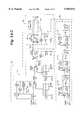
- FIGS. 3A and 3Btaken together, is a combination detailed component level circuit diagram/schematic block diagram showing the individual components of the RFID system of FIG. 2, as well as additional components of an RFID system in accordance with the present invention
- FIG. 4is a schematic block diagram of an intelligent tag suitable for use with the present invention.
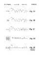
- FIGS. 5A-5Eare tag response signals at different stages in the system of FIGS. 3A and 3B;
- FIG. 6is a simplified circuit diagram of a portion of FIGS. 3A and 3B;
- FIG. 7is a diagram of the outputs of a flip-flop in FIG. 6;
- FIG. 8is a schematic block diagram of a conventional scheme for producing phase split signals to drive an RFID transmitter antenna.
- FIG. 9is a schematic block diagram of a scheme for producing phase split signals to drive an RFID transmitter antenna in accordance with the present invention.
- the system architecture of the RFID system in the present inventionincludes a plurality of elements for reducing noise within the RFID system.
- the resultant RFID systemhas better detection capabilities, or equivalently, a greater read range for RFID tags. Key elements are summarized herein as follows:
- the systemprovides a local oscillator with low amplitude and phase noise. Noise components are minimized by starting with a low noise crystal oscillator having an output frequency which is an integer multiple n of the desired RF field frequency, and then dividing this frequency by the integer multiple n.
- n2
- the RF field frequencyis 13.56 MHz.
- the crystal oscillatorhas an output frequency of 27.12 MHz.
- the output frequencyis passed through a frequency divider (a "divide by 2" circuit in this example) to obtain a reduced noise 13.56 MHz signal for driving the transmitter antenna.
- the same principlemay be used for values of n greater than 2.
- an oscillatoris selected which has an output frequency of 54.24 MHz and this signal is passed through a 4 ⁇ frequency divider (i.e., a "divide by 4" circuit) to obtain a reduced noise 13.56 MHz signal for driving the transmitter antenna.
- a 4 ⁇ frequency divideri.e., a "divide by 4" circuit
- Fiber opticsare used to communicate analog tag response signals from the output of the receiver circuit to the input of the tag response signal analyzing circuitry (which includes a digital signal processor (DSP)).
- DSPdigital signal processor
- the system architectureis thus physically separated into analog and digital sections.
- the fiber opticscreates electrical isolation between the two sections, breaking ground loops, stopping internal switching noise from the DSP from entering the sensitive front end detector (i.e., the receiver circuitry), and preventing common mode signals from interfering with the desired RFID tag signal.
- Filteringis provided on the DC power lines which prevents extraneous signals, either internal or external, from interfering with desired tag signals.
- the filteringis targeted toward high and low frequency interference, which may be common mode or differential.
- FIG. 2is a schematic block diagram of selected portions of an RFID system 16 depicted to selectively highlight the three above-identified elements of the present invention.
- FIGS. 3A and 3Btaken together, provide a combination expanded, component level circuit diagram/schematic block diagram of one preferred embodiment of the RFID system 16 having the selected portions shown in FIG. 2, as well as additional portions. The circuit components of FIGS. 3A and 3B are described in conjunction with the elements of FIG. 2.
- the system 16includes a transceiver module 18 (FIG. 3A), a tag response signal analyzing module 20 (FIG. 3B) and an optical interface in the form of an optical fiber interface 22 (FIGS. 3A and 3B).
- the transceiver module 18includes a conventional receiver circuit 24 having an AM receiver.
- the receiver circuit 24demodulates the data from the intelligent tag 28 (FIG. 4). Amplitude perturbations on the RF carrier are detected, amplified and limited by coupling energy directly from the receiver antenna. Detection, amplification and limiting are thus performed in the receiver circuit 24.
- the receiver circuit 24outputs a demodulated tag response signal upon detecting an article 26 tagged with an intelligent tag 28 in a detection zone 30.
- the transceiver module 18is connected to a conventional transmitter/receiver antenna assembly 32 which includes a transmitter loop antenna 34 for creating a detection zone and a receiver loop antenna 36 for picking up response signals transmitted from one or more intelligent tags 28.
- the antennas 34 and 36may be separated, or may be colocated (i.e., both arranged on the same physical antenna).
- the transceiver module 18is placed in close proximity to the driven antenna element(s).
- the antenna assembly 32may be arranged as shown in FIG. 1 or in any other conventional manner.
- the transmitter loop antenna 36has a predetermined fundamental field frequency. In the example described herein, the frequency is 13.56 MHz. However, the scope of the invention includes any frequency which is suitable for detecting resonant intelligent tags.
- the tag response signal analyzing module 20may be located in close proximity to the antenna assembly 32 and transceiver module 18, or it may be located remotely with respect to the antenna assembly 32 and transceiver module 18.
- the tag response signal analyzing module 20includes an optical input, an A/D converter 65, and a conventional digital signal processing circuit (hereafter, digital signal processor 38 or DSP 38) which processes the digitized and quantized analog tag response signal and outputs intelligent tag data therefrom.
- the DSP 38is preferably housed in a shielded box.
- the interface 22includes an optical transmitter 40, an optical receiver 42 and a fiber optic cable or optical fiber 44 connected at one end to the optical transmitter 40 and connected at the other end to the optical receiver 42.
- the optical transmitter 40 and optical receiver 42may be physically mounted on respective boards associated with the transceiver module 18 and tag response signal analyzing module 20 as shown in FIGS. 2, 3A and 3B, or they may be external to the boards associated with the transceiver module 18 and tag response signal analyzing module 20 (not shown).
- the optical fiber 44may be any suitable length for connecting the respective boards, and may have one or more repeaters or optical amplifiers connected along its path, if necessary to maintain signal strength.
- the optical fiber 44significantly reduces noise in the tag response signal by providing electrical isolation and breaking ground loops associated with hardwired connections, stopping internal switching noise from the DSP 38 from entering the receiver circuit 24, and preventing common mode signals from interfering with the desired tag response signal.
- the preferred resonant intelligent tag for use with the present inventionis a conventional RFID tag.
- FIG. 4shows general details of a sample RFID tag 28 suitable for use with the present invention.
- the intelligent tag 28includes a passive resonant radio frequency (RF) circuit 50 for detecting when the tag 28 is within a zone monitored by a reader or interrogator, as is well known in the art.
- RFradio frequency
- One well-known type of circuit 50has a coil antenna 52 and a capacitor 54 which together form a resonant circuit with a predetermined (operational) resonant frequency (i.e., the selected radio frequency).
- Power for the intelligent tag 28is derived from the antenna 52 in a conventional manner.
- the intelligent tag 28includes an integrated circuit (IC) 56 for providing "intelligence" to the intelligent tag 28.
- the IC 56is connected to the circuit 50.
- the IC 56includes a programmable memory 58, as described below, for storing bits of identification or other data.
- the IC 56outputs a data stream comprising stored data when sufficient power is applied thereto.
- the data streamcreates a series of data pulses by switching an extra capacitor (not shown) across the coil antenna 52 for the duration of the data pulses. This changes the resonant frequency of the RF circuit 50, detuning it from the operational frequency.
- the RF circuit 50instead of the RF circuit 50 returning a simple response signal at a single operational resonant frequency, it returns a modulated signal containing a packet of preprogrammed information from the memory 58.
- the packet of information(data pulses) is received and processed by interrogator receiving circuitry and is decoded (if necessary) to provide identification and/or other information about the tagged article.
- Other methods of using the data in the IC memory 58 to output identification data from the intelligent tag 28are within the scope of the invention.
- the IC 56is preferably also a passive device and is powered in the same manner as the RF circuit 50 (i.e., by using energy received at the antenna 52 from the interrogator transmitter signal).
- the intelligent tag 28is thus a so-called RFID tag.
- Other types of RFID tagsmay be used with the present invention. Examples of other RFID tags which have circuitry suitable for use as part of the circuitry of the intelligent tag 28 are shown in U.S. Pate. Nos. 5,446,447 (Carney et al.), 5,430,441 (Bickley et al.), and 5,347,263 (Carroll et al.).
- FIGS. 5A-5Eshow sample tag response signals originating from the intelligent tag 28 at the different stages of the circuit elements of FIGS. 2, 3A and 3B.
- FIG. 5Ashows a portion of the unprocessed demodulated analog tag response signal at the output of the receiver circuit 24, labeled in FIG. 3A and FIG. 5A as signal 60.
- a typical analog tag response signalmay have 154 bits and a peak voltage level in the range of about 50 millivolts.
- the signalis "analog" because it has a continuously variable voltage level and noise, compared to a digital signal which has clearly defined discrete values (e.g., 1, 2, 3, . . . ) which are ultimately expressed in groups of bits, and are represented by high and low logic levels.
- FIG. 5Bshows a portion of the tag response signal as it appears in the optical fiber 44 and after being processed by the optical transmitter 40.
- the tag response signal at this stageis labeled in FIGS. 3A and 3B, and in FIG. 5B as signal 62.
- the signal 62has the same waveform as the signal 60, but the amplitude represents light intensity, not voltage.
- FIG. 5Cshows a portion of the tag response signal as it appears at the output of the optical receiver 42 and before being input into the tag response signal analyzing module 20.
- the tag response signal at this stageis labeled in FIG. 3B and FIG. 5C as signal 64.
- the signal 64has the same waveform as the signal 62, but the amplitude now represents an analog electrical voltage.
- the signal 64is thus identical to the signal 60, assuming ideally operating conversion circuitry and a lossless optical fiber 44.
- the analog electrical voltageis quantized in an A/D converter 65 shown in FIG. 3B which converts the analog voltage to digital data for processing by the DSP 38.
- the signal at the output of the A/D converter 65is a sequence of 10 bit words, represented in FIG. 5D as discrete, quantized values of the signal 64 which are input into the DSP 38.
- FIG. 5Eshows a portion of the intelligent tag data 66 output from the DSP 38.
- This dataprovides the identification information of the intelligent tag 28 (e.g., RFID tag data in the case wherein the intelligent tag 28 is an RFID tag).
- the tag output signalis labeled in FIG. 3B and FIG. 5E as signal 66.
- FIGS. 5D and 5Edo not represent the signals shown in FIGS. 5A-5C at the same respective points in time, nor are the time periods in FIGS. 5D and 5E correlated with each other or with the time periods of FIGS. 5A-5C.
- FIGS. 5D and 5Eare provided to illustrate the digital characteristics of a tag response signal, compared to the analog nature of the signal in FIGS. 5A-5C.
- U.S. Pat. No. 5,288,980discloses that the communication link between an electronic data processor and a pass/not pass logic circuit may be a fiber optic cable.
- U.S. Pat. No. 5,440,300discloses a multiple embedded structure network wherein several smart structures embedded within panels are powered and interrogated by a network of conformal powering and data reception interrogation interface units which are connected by and serve as nodes along a common power/data bus cable.
- the cablemay be a fiber optic cable.
- FIGS. 2, 3A and 3Balso show the second highlighted noise-reducing element of the present invention, namely a low noise signal generator 68 for driving the transmitter of the antenna assembly 32 at its fundamental field frequency.
- the signal generatorincludes an oscillator 70 having an output frequency which is an integer multiple n of the fundamental field frequency, and a frequency divider 72 (hereafter, “divide by n circuit 72") connected to the oscillator output, wherein n ⁇ 2.
- the output of the signal generator 68is used to drive the transmitter of the antenna assembly 32 with the n-divided oscillator frequency.
- the output of the signal generator 68is connected to a resonant circuit driver or power driver circuit 86, which, in turn, drives the transmitter antenna 34.
- One preferred power driver circuit 86is a type of Class E amplifier disclosed in U.S. patent application Ser. No. 08/911,843, filed Aug. 15, 1997, entitled “Drive Circuit For Reactive Loads,” which is incorporated herein by reference.
- One embodiment of such a power driver circuit 86is shown in FIG. 3A.
- the scope of the inventionincludes any suitable switched amplifier which accepts a digital input, including conventional Class C, D or E amplifiers.
- the oscillator 70may be mounted to the transceiver module 18 as shown in FIG. 3A, or the oscillator 70 may be external to the transceiver module 18 (not shown). In the external configuration, the oscillator output may be received by fiber optic circuitry 76. If so, the transceiver module 18 uses circuitry 77 to sense a "drop out," or an absence of the external oscillator, to synchronize to neighboring transceiver modules 18, either in phase by using jumper J5, or 180 degrees out of phase by using jumper J4.
- FIG. 3Ashows a preferred embodiment of the present invention wherein the divide by n circuit 72 is implemented with one or more cascaded toggle flip-flops.
- nthe number of flip-flops.
- the field frequencyis 13.56 MHz in the illustrated example.
- an oscillator 70is chosen which has an output frequency of 27.12 MHz.
- nis preferably an even number.
- multiple flip-flopsmay be cascaded to create divide by 4, 6, 8, etc . . . circuits.
- the flip-flop output signalsare obtained from the Q and Q outputs of the final stage flip-flop.
- nis an odd number, the circuit implementation is more complicated.
- One odd number implementationuses a counter and decoder to decode counter outputs.
- the scope of the inventionincludes values of n ⁇ 2. A practical range of values for n is 16>n ⁇ 2.
- the theory behind the noise reducing function of the signal generator 68is that a frequency divider attenuates noise power in the drive signal but does not attenuate the signal power of the drive signal.
- nthe amplitude of the phase noise sidebands at any given frequency offset are divided in half, whereas the amplitude of the signal portion is not divided.
- the noise in the drive signal at a particular frequency offsetis ⁇ DS
- the resultant noise in the drive signal after being fed through the divide by 2 circuitis 1/2 ⁇ DS at the same frequency offset.
- the low noise oscillator scheme described abovesignificantly reduces noise in the RF field, thereby allowing the read range to be increased by a significant percentage compared to prior art RFID systems which do not use any such scheme. For example, a 10-20% improvement in detectability may be achieved using this scheme.
- FIGS. 2 and 3Aalso show the third highlighted noise-reducing element of the present invention, namely the use of filtering on the DC power lines.
- the tag response signal analyzing module 20provides isolated DC power to the transceiver module 18, which, in turn, uses the DC power to synthesize and drive RF currents in the transmitter antenna 34 at the fundamental field frequency.
- the DC power lines for the transceiver module 18contain high and low frequency common mode filters 76 and 78, and high and low frequency differential mode suppression filters 80.
- FIG. 3Aalso shows voltage regulators 82 and 84 for powering the circuits of the RFID system 16.
- FIG. 6is a simplified circuit diagram which highlights portions of the preferred embodiment of the present invention wherein one or more toggle flip-flops 72 (one flip-flop in the illustrated divide by 2 embodiment) provide the dual function of (1) frequency dividing, and (2) providing non-phase inverted and phase inverted output signals to drive a transmitter. (The circuitry of FIG. 6 is shown in detail in FIG. 3A.)
- the output of the divide by 2 circuitis the Q and Q outputs of the flip-flop 72.
- the two outputshave a 180 degree phase difference, and the same frequency, as illustrated in FIG. 7.
- the Q outputis labeled as having a 0 degree phase, and may be referred to as the "non-phase inverted output”
- the Q outputis labeled as having a 180 degree phase, and may be referred to as the "phase inverted output.”
- the resultant outputthus has a push-pull characteristic.
- the antenna 34produces a continuous wave signal.
- a continuous wave signalprovides better time opportunities for tag detection compared to a pulsed or burst wave scheme for a transmitter antenna, such as disclosed in FIG.
- FIG. 3 of U.S. Pat. No. 4,274,089discloses sending the Q output of a frequency dividing flip-flop to a transmitter of a resonant tag, the Q output (i.e., phase inverted output) is not sent to the tag transmitter.
- phase splitpush-pull
- a transformeris an analog device and generates significant noise, thereby defeating the goal of reducing system noise.
- the present inventionmaintains the drive signal in digital form as close as possible to the final stage and uses a digital device (flip-flop) to generate the phase split signals, thereby reducing the opportunities for noise to be generated in the system.
- FIGS. 8 and 9illustrate how the present invention uses digital signals as close as possible to the final stage to reduce noise in the drive signal circuitry.
- FIG. 8is a conventional scheme 90 for driving an RFID transmitter antenna to produce a continuous wave signal.
- an analog device 92such as a transformer, produces the phase split signals.
- the analog output of the transformeris amplified by a resonant circuit driver 94 which accepts an analog input, and the output of the driver is sent to the transmitter antenna 34.
- FIG. 9shows the scheme 96 in accordance with the present invention.
- a digital devicenamely one or more flip-flops 72, produces the phase split signals.
- the digital output of the flip-flop(s) 72is input to a switched amplifier 96, which may be any suitable Class C, D or E amplifier capable of accepting a digital input.
- a switched amplifier 96which may be any suitable Class C, D or E amplifier capable of accepting a digital input.
- One such amplifieris disclosed in U.S. patent application Ser. No. 08/911,843, filed Aug. 15, 1997, entitled "Drive Circuit For Reactive Loads, an implementation of which is shown in FIG. 3A (see power driver circuit 86).
- a less preferred embodiment of the RFID system 16which is within the scope of the present invention uses only one output or one phase of the flip-flop 72. This scheme is provides only one-half of the signal voltage for a given input voltage compared to the preferred two phase scheme, but still provides the desired signal noise reduction and the continuous wave.
- the RFID system 16uses an amplitude-modulated response signal.
- modulation schemesare within the scope of the invention, such as frequency modulation, pulse modulation, and phase modulation.
- optical interface disclosed hereinis an optical fiber interface.
- other optical or light interface schemesmay be used which permit light transmission and receiving of the analog tag response signal over a defined distance.
- the noise reduction schemesmay be used in RFID systems that employ other types of resonant intelligent tag.
- the noise reduction schemes described aboveimprove tag detection and allow for a significantly increased read range.
- the present inventionthus addresses a long-felt, and heretofore, unmet need in the industry for an RFID system with such improved capabilities.
Landscapes
- Engineering & Computer Science (AREA)
- Physics & Mathematics (AREA)
- Electromagnetism (AREA)
- General Physics & Mathematics (AREA)
- Signal Processing (AREA)
- Automation & Control Theory (AREA)
- Computer Security & Cryptography (AREA)
- Health & Medical Sciences (AREA)
- Computer Networks & Wireless Communication (AREA)
- Toxicology (AREA)
- Artificial Intelligence (AREA)
- Computer Vision & Pattern Recognition (AREA)
- Theoretical Computer Science (AREA)
- General Health & Medical Sciences (AREA)
- Near-Field Transmission Systems (AREA)
- Electronic Switches (AREA)
Abstract
Description
Claims (4)
Priority Applications (19)
| Application Number | Priority Date | Filing Date | Title |
|---|---|---|---|
| US09/122,121US5959531A (en) | 1998-07-24 | 1998-07-24 | Optical interface between receiver and tag response signal analyzer in RFID system for detecting low power resonant tags |
| ARP990103385AAR019377A1 (en) | 1998-07-24 | 1999-07-12 | RADIO FREQUENCY IDENTIFICATION PROVISION. |
| KR1020017000434AKR100660409B1 (en) | 1998-07-24 | 1999-07-13 | Wireless recognition system for detecting low power resonance tags |
| EP99935548AEP1099200B1 (en) | 1998-07-24 | 1999-07-13 | Optical interface between receiver and tag response signal analyser in RFID system for detecting low power resonant tags |
| AT99935548TATE281671T1 (en) | 1998-07-24 | 1999-07-13 | OPTICAL INTERFACE BETWEEN RECEIVER AND EVALUATION UNIT FOR RESPONSE SIGNALS OF A LABEL IN RFID SYSTEMS FOR DETECTING POWERFUL RESONANCE LABELS |
| DE69921658TDE69921658T2 (en) | 1998-07-24 | 1999-07-13 | Optical interface between receiver and evaluation unit for response signals of a label in RFID systems for the detection of low-power resonance tags |
| CNB998089621ACN1135509C (en) | 1998-07-24 | 1999-07-13 | Radio frequency identification system for detecting resonant smart tag-attached object |
| ES03020341TES2262929T3 (en) | 1998-07-24 | 1999-07-13 | LOW NOISE SIGNAL GENERATOR FOR USE IN A RADIO FREQUENCY IDENTIFICATION SYSTEM (RFID). |
| CA002338640ACA2338640C (en) | 1998-07-24 | 1999-07-13 | Rfid system for detecting low power resonant tags |
| CNB031408206ACN1238732C (en) | 1998-07-24 | 1999-07-13 | Low nose signal generator for radio-frequency recognition system |
| ES99935548TES2233058T3 (en) | 1998-07-24 | 1999-07-13 | OPTICAL INTERFACE BETWEEN RECEIVER AND ANALYZER OF SIGNAL RESPONSE OF A LABEL IN AN RFID RADIO FREQUENCY IDENTIFICATION SYSTEM TO DETECT LOW POWER RESONANT LABELS. |
| EP03020341AEP1376445B1 (en) | 1998-07-24 | 1999-07-13 | Low noise signal generator for use with an RFID system |
| DE69930975TDE69930975T2 (en) | 1998-07-24 | 1999-07-13 | Low-noise signal generator for use in an RFID system |
| CA002624853ACA2624853A1 (en) | 1998-07-24 | 1999-07-13 | Rfid system for detecting low power resonant tags |
| AT03020341TATE323910T1 (en) | 1998-07-24 | 1999-07-13 | LOW NOISE SIGNAL GENERATOR FOR USE IN AN RFID SYSTEM |
| AU51007/99AAU753617B2 (en) | 1998-07-24 | 1999-07-13 | Rfid system for detecting low power resonant tags |
| PCT/US1999/015884WO2000005692A1 (en) | 1998-07-24 | 1999-07-13 | Rfid system for detecting low power resonant tags |
| JP2000561598AJP4445672B2 (en) | 1998-07-24 | 1999-07-13 | High frequency identification system for low power resonant tag detection |
| TW088112550ATW434522B (en) | 1998-07-24 | 1999-07-30 | Optical interface between receiver and tag response signal analyzer in RFID system for detecting low power resonant tags |
Applications Claiming Priority (1)
| Application Number | Priority Date | Filing Date | Title |
|---|---|---|---|
| US09/122,121US5959531A (en) | 1998-07-24 | 1998-07-24 | Optical interface between receiver and tag response signal analyzer in RFID system for detecting low power resonant tags |
Publications (1)
| Publication Number | Publication Date |
|---|---|
| US5959531Atrue US5959531A (en) | 1999-09-28 |
Family
ID=22400755
Family Applications (1)
| Application Number | Title | Priority Date | Filing Date |
|---|---|---|---|
| US09/122,121Expired - LifetimeUS5959531A (en) | 1998-07-24 | 1998-07-24 | Optical interface between receiver and tag response signal analyzer in RFID system for detecting low power resonant tags |
Country Status (3)
| Country | Link |
|---|---|
| US (1) | US5959531A (en) |
| AR (1) | AR019377A1 (en) |
| TW (1) | TW434522B (en) |
Cited By (89)
| Publication number | Priority date | Publication date | Assignee | Title |
|---|---|---|---|---|
| US20020152604A1 (en)* | 2001-04-23 | 2002-10-24 | Debraal John Charles | Method and system for forming electrically conductive pathways |
| US20030027597A1 (en)* | 2001-07-31 | 2003-02-06 | Lagrotta James T. | Use of over-the-air optical link within a geographically distributed base station |
| WO2003030408A1 (en)* | 2001-10-02 | 2003-04-10 | Pharmaseq, Inc. | Microtransponder sensing system |
| US20030098783A1 (en)* | 1999-12-15 | 2003-05-29 | Frederic Pagnol | Transponder reading device |
| US20030183226A1 (en)* | 2000-07-15 | 2003-10-02 | Brand Peter John | Medicament dispenser |
| US6641035B1 (en)* | 2000-08-11 | 2003-11-04 | Matsushita Electric Industrial Co., Ltd. | Card made of fluorescent material and card reader for use with the card |
| US6641034B1 (en) | 2000-08-11 | 2003-11-04 | Matsushita Electric Industrial Co., Ltd. | Card reader with a light-emitting bezel |
| WO2004010885A1 (en)* | 2002-07-25 | 2004-02-05 | Diomed Inc. | Laser system |
| US20040061612A1 (en)* | 2002-09-26 | 2004-04-01 | Paradiso Joseph A. | Tag interrogation with observable response signal |
| US6724308B2 (en)* | 2000-08-11 | 2004-04-20 | Escort Memory Systems | RFID tracking method and system |
| US6737973B2 (en)* | 2001-10-15 | 2004-05-18 | 3M Innovative Properties Company | Amplifier modulation |
| US6758397B2 (en)* | 2001-03-31 | 2004-07-06 | Koninklijke Philips Electronics N.V. | Machine readable label reader system for articles with changeable status |
| US20040130445A1 (en)* | 2003-01-03 | 2004-07-08 | Edwin Graves | System and method for fiber optic communication with safety-related alarm systems |
| US6779246B2 (en) | 2001-04-23 | 2004-08-24 | Appleton Papers Inc. | Method and system for forming RF reflective pathways |
| US20050184872A1 (en)* | 2004-02-23 | 2005-08-25 | Clare Thomas J. | Identification marking and method for applying the identification marking to an item |
| US20050183817A1 (en)* | 2004-02-23 | 2005-08-25 | Eric Eckstein | Security tag system for fabricating a tag including an integrated surface processing system |
| US20050184873A1 (en)* | 2004-02-23 | 2005-08-25 | Eric Eckstein | Tag having patterned circuit elements and a process for making same |
| US20050183264A1 (en)* | 2004-02-23 | 2005-08-25 | Eric Eckstein | Method for aligning capacitor plates in a security tag and a capacitor formed thereby |
| US20050187837A1 (en)* | 2004-02-23 | 2005-08-25 | Eric Eckstein | Method and system for determining billing information in a tag fabrication process |
| US20050242953A1 (en)* | 2003-10-24 | 2005-11-03 | Toshiba Teli Corporation | Object tagged with RFID tag and device and method for processing it |
| US7009517B2 (en) | 2000-05-24 | 2006-03-07 | Glaxo Group Limited | Method for monitoring objects with transponders |
| US20060049259A1 (en)* | 1999-09-22 | 2006-03-09 | Sony Corporation | Information processing system, hand held cellular phone, and information processing method |
| US20060092013A1 (en)* | 2004-10-07 | 2006-05-04 | West Pharmaceutical Services, Inc. | Closure for a container |
| ES2253104A1 (en)* | 2004-10-20 | 2006-05-16 | Alberto Murgui Faubell | Resonant label detection system for antitheft equipment has receivers that are activated before and after series of pulses is generated to detect signal emitted by resonant circuits |
| US7091864B2 (en) | 2000-06-06 | 2006-08-15 | Glaxo Group Limited | Sample container with radiofrequency identifier tag |
| US7151456B2 (en) | 2000-02-26 | 2006-12-19 | Glaxo Group Limited | Medicament dispenser |
| US7258276B2 (en) | 2000-10-20 | 2007-08-21 | Promega Corporation | Radio frequency identification method and system of distributing products |
| US20070206701A1 (en)* | 2006-03-03 | 2007-09-06 | Applied Wireless Identification Group, Inc. | RFID reader with digital waveform encoding and digital decoding |
| US20070286599A1 (en)* | 2006-06-12 | 2007-12-13 | Michael Sauer | Centralized optical-fiber-based wireless picocellular systems and methods |
| WO2007051165A3 (en)* | 2005-10-27 | 2008-06-12 | Charles L Manto | System and method for providing certifiable electromagnetic pulse and rfi protection through mass-produced shielded containers and rooms |
| WO2008010884A3 (en)* | 2006-06-12 | 2008-06-26 | Corning Cable Sys Llc | Centralized optical-fiber-based rfid systems and methods |
| US7590354B2 (en) | 2006-06-16 | 2009-09-15 | Corning Cable Systems Llc | Redundant transponder array for a radio-over-fiber optical fiber cable |
| US20090259220A1 (en)* | 2008-04-09 | 2009-10-15 | Angiodynamics, Inc. | Treatment Devices and Methods |
| US7627250B2 (en) | 2006-08-16 | 2009-12-01 | Corning Cable Systems Llc | Radio-over-fiber transponder with a dual-band patch antenna system |
| US7661591B2 (en) | 2000-10-20 | 2010-02-16 | Promega Corporation | RF point of sale and delivery method and system using communication with remote computer and having features to read a large number of RF tags |
| US7704346B2 (en) | 2004-02-23 | 2010-04-27 | Checkpoint Systems, Inc. | Method of fabricating a security tag in an integrated surface processing system |
| US7710275B2 (en) | 2007-03-16 | 2010-05-04 | Promega Corporation | RFID reader enclosure and man-o-war RFID reader system |
| US7787823B2 (en) | 2006-09-15 | 2010-08-31 | Corning Cable Systems Llc | Radio-over-fiber (RoF) optical fiber cable system with transponder diversity and RoF wireless picocellular system using same |
| US7848654B2 (en) | 2006-09-28 | 2010-12-07 | Corning Cable Systems Llc | Radio-over-fiber (RoF) wireless picocellular system with combined picocells |
| US20110148636A1 (en)* | 2009-12-17 | 2011-06-23 | 3M Innovative Properties Company | Detection system |
| US20110200325A1 (en)* | 2010-02-15 | 2011-08-18 | Andrey Kobyakov | Dynamic Cell Bonding (DCB) for Radio-over-Fiber (RoF)-Based Networks and Communication Systems and Related Methods |
| US8111998B2 (en) | 2007-02-06 | 2012-02-07 | Corning Cable Systems Llc | Transponder systems and methods for radio-over-fiber (RoF) wireless picocellular systems |
| US8175459B2 (en) | 2007-10-12 | 2012-05-08 | Corning Cable Systems Llc | Hybrid wireless/wired RoF transponder and hybrid RoF communication system using same |
| US8548330B2 (en) | 2009-07-31 | 2013-10-01 | Corning Cable Systems Llc | Sectorization in distributed antenna systems, and related components and methods |
| US8644844B2 (en) | 2007-12-20 | 2014-02-04 | Corning Mobileaccess Ltd. | Extending outdoor location based services and applications into enclosed areas |
| USD710783S1 (en)* | 2013-03-13 | 2014-08-12 | Landscape Forms, Inc. | Bike rack |
| US8867919B2 (en) | 2007-07-24 | 2014-10-21 | Corning Cable Systems Llc | Multi-port accumulator for radio-over-fiber (RoF) wireless picocellular systems |
| US8873585B2 (en) | 2006-12-19 | 2014-10-28 | Corning Optical Communications Wireless Ltd | Distributed antenna system for MIMO technologies |
| US9037143B2 (en) | 2010-08-16 | 2015-05-19 | Corning Optical Communications LLC | Remote antenna clusters and related systems, components, and methods supporting digital data signal propagation between remote antenna units |
| US9042732B2 (en) | 2010-05-02 | 2015-05-26 | Corning Optical Communications LLC | Providing digital data services in optical fiber-based distributed radio frequency (RF) communication systems, and related components and methods |
| US9112611B2 (en) | 2009-02-03 | 2015-08-18 | Corning Optical Communications LLC | Optical fiber-based distributed antenna systems, components, and related methods for calibration thereof |
| US9178635B2 (en) | 2014-01-03 | 2015-11-03 | Corning Optical Communications Wireless Ltd | Separation of communication signal sub-bands in distributed antenna systems (DASs) to reduce interference |
| US9184843B2 (en) | 2011-04-29 | 2015-11-10 | Corning Optical Communications LLC | Determining propagation delay of communications in distributed antenna systems, and related components, systems, and methods |
| US9219879B2 (en) | 2009-11-13 | 2015-12-22 | Corning Optical Communications LLC | Radio-over-fiber (ROF) system for protocol-independent wired and/or wireless communication |
| US9240835B2 (en) | 2011-04-29 | 2016-01-19 | Corning Optical Communications LLC | Systems, methods, and devices for increasing radio frequency (RF) power in distributed antenna systems |
| US9247543B2 (en) | 2013-07-23 | 2016-01-26 | Corning Optical Communications Wireless Ltd | Monitoring non-supported wireless spectrum within coverage areas of distributed antenna systems (DASs) |
| US9258052B2 (en) | 2012-03-30 | 2016-02-09 | Corning Optical Communications LLC | Reducing location-dependent interference in distributed antenna systems operating in multiple-input, multiple-output (MIMO) configuration, and related components, systems, and methods |
| US9325429B2 (en) | 2011-02-21 | 2016-04-26 | Corning Optical Communications LLC | Providing digital data services as electrical signals and radio-frequency (RF) communications over optical fiber in distributed communications systems, and related components and methods |
| US9357551B2 (en) | 2014-05-30 | 2016-05-31 | Corning Optical Communications Wireless Ltd | Systems and methods for simultaneous sampling of serial digital data streams from multiple analog-to-digital converters (ADCS), including in distributed antenna systems |
| US9385810B2 (en) | 2013-09-30 | 2016-07-05 | Corning Optical Communications Wireless Ltd | Connection mapping in distributed communication systems |
| US9420542B2 (en) | 2014-09-25 | 2016-08-16 | Corning Optical Communications Wireless Ltd | System-wide uplink band gain control in a distributed antenna system (DAS), based on per band gain control of remote uplink paths in remote units |
| US9455784B2 (en) | 2012-10-31 | 2016-09-27 | Corning Optical Communications Wireless Ltd | Deployable wireless infrastructures and methods of deploying wireless infrastructures |
| US9525488B2 (en) | 2010-05-02 | 2016-12-20 | Corning Optical Communications LLC | Digital data services and/or power distribution in optical fiber-based distributed communications systems providing digital data and radio frequency (RF) communications services, and related components and methods |
| US9525472B2 (en) | 2014-07-30 | 2016-12-20 | Corning Incorporated | Reducing location-dependent destructive interference in distributed antenna systems (DASS) operating in multiple-input, multiple-output (MIMO) configuration, and related components, systems, and methods |
| US9531452B2 (en) | 2012-11-29 | 2016-12-27 | Corning Optical Communications LLC | Hybrid intra-cell / inter-cell remote unit antenna bonding in multiple-input, multiple-output (MIMO) distributed antenna systems (DASs) |
| US9602210B2 (en) | 2014-09-24 | 2017-03-21 | Corning Optical Communications Wireless Ltd | Flexible head-end chassis supporting automatic identification and interconnection of radio interface modules and optical interface modules in an optical fiber-based distributed antenna system (DAS) |
| US9621293B2 (en) | 2012-08-07 | 2017-04-11 | Corning Optical Communications Wireless Ltd | Distribution of time-division multiplexed (TDM) management services in a distributed antenna system, and related components, systems, and methods |
| US9647758B2 (en) | 2012-11-30 | 2017-05-09 | Corning Optical Communications Wireless Ltd | Cabling connectivity monitoring and verification |
| US9661781B2 (en) | 2013-07-31 | 2017-05-23 | Corning Optical Communications Wireless Ltd | Remote units for distributed communication systems and related installation methods and apparatuses |
| US9673904B2 (en) | 2009-02-03 | 2017-06-06 | Corning Optical Communications LLC | Optical fiber-based distributed antenna systems, components, and related methods for calibration thereof |
| US9681313B2 (en) | 2015-04-15 | 2017-06-13 | Corning Optical Communications Wireless Ltd | Optimizing remote antenna unit performance using an alternative data channel |
| US9715157B2 (en) | 2013-06-12 | 2017-07-25 | Corning Optical Communications Wireless Ltd | Voltage controlled optical directional coupler |
| US9729267B2 (en) | 2014-12-11 | 2017-08-08 | Corning Optical Communications Wireless Ltd | Multiplexing two separate optical links with the same wavelength using asymmetric combining and splitting |
| US9730228B2 (en) | 2014-08-29 | 2017-08-08 | Corning Optical Communications Wireless Ltd | Individualized gain control of remote uplink band paths in a remote unit in a distributed antenna system (DAS), based on combined uplink power level in the remote unit |
| US9775123B2 (en) | 2014-03-28 | 2017-09-26 | Corning Optical Communications Wireless Ltd. | Individualized gain control of uplink paths in remote units in a distributed antenna system (DAS) based on individual remote unit contribution to combined uplink power |
| US9807700B2 (en) | 2015-02-19 | 2017-10-31 | Corning Optical Communications Wireless Ltd | Offsetting unwanted downlink interference signals in an uplink path in a distributed antenna system (DAS) |
| US9948349B2 (en) | 2015-07-17 | 2018-04-17 | Corning Optical Communications Wireless Ltd | IOT automation and data collection system |
| US9974074B2 (en) | 2013-06-12 | 2018-05-15 | Corning Optical Communications Wireless Ltd | Time-division duplexing (TDD) in distributed communications systems, including distributed antenna systems (DASs) |
| US10096909B2 (en) | 2014-11-03 | 2018-10-09 | Corning Optical Communications Wireless Ltd. | Multi-band monopole planar antennas configured to facilitate improved radio frequency (RF) isolation in multiple-input multiple-output (MIMO) antenna arrangement |
| US10110308B2 (en) | 2014-12-18 | 2018-10-23 | Corning Optical Communications Wireless Ltd | Digital interface modules (DIMs) for flexibly distributing digital and/or analog communications signals in wide-area analog distributed antenna systems (DASs) |
| US10128951B2 (en) | 2009-02-03 | 2018-11-13 | Corning Optical Communications LLC | Optical fiber-based distributed antenna systems, components, and related methods for monitoring and configuring thereof |
| US10136200B2 (en) | 2012-04-25 | 2018-11-20 | Corning Optical Communications LLC | Distributed antenna system architectures |
| US10135533B2 (en) | 2014-11-13 | 2018-11-20 | Corning Optical Communications Wireless Ltd | Analog distributed antenna systems (DASS) supporting distribution of digital communications signals interfaced from a digital signal source and analog radio frequency (RF) communications signals |
| US10187151B2 (en) | 2014-12-18 | 2019-01-22 | Corning Optical Communications Wireless Ltd | Digital-analog interface modules (DAIMs) for flexibly distributing digital and/or analog communications signals in wide-area analog distributed antenna systems (DASs) |
| US10236924B2 (en) | 2016-03-31 | 2019-03-19 | Corning Optical Communications Wireless Ltd | Reducing out-of-channel noise in a wireless distribution system (WDS) |
| USRE47599E1 (en) | 2000-10-20 | 2019-09-10 | Promega Corporation | RF point of sale and delivery method and system using communication with remote computer and having features to read a large number of RF tags |
| US10560214B2 (en) | 2015-09-28 | 2020-02-11 | Corning Optical Communications LLC | Downlink and uplink communication path switching in a time-division duplex (TDD) distributed antenna system (DAS) |
| US10659163B2 (en) | 2014-09-25 | 2020-05-19 | Corning Optical Communications LLC | Supporting analog remote antenna units (RAUs) in digital distributed antenna systems (DASs) using analog RAU digital adaptors |
| US11178609B2 (en) | 2010-10-13 | 2021-11-16 | Corning Optical Communications LLC | Power management for remote antenna units in distributed antenna systems |
Families Citing this family (1)
| Publication number | Priority date | Publication date | Assignee | Title |
|---|---|---|---|---|
| TW201112126A (en) | 2009-09-18 | 2011-04-01 | Univ Nat Taiwan Science Tech | Radio frequency identification tag |
Citations (20)
| Publication number | Priority date | Publication date | Assignee | Title |
|---|---|---|---|---|
| US3737676A (en)* | 1971-11-18 | 1973-06-05 | J Fletcher | Low phase noise digital frequency divider |
| US3959737A (en)* | 1974-11-18 | 1976-05-25 | Engelmann Microwave Co. | Frequency synthesizer having fractional frequency divider in phase-locked loop |
| US4009455A (en)* | 1974-09-12 | 1977-02-22 | Matsushita Electric Industrial Co., Ltd. | Phase locked loop angle modulation system with large modulation index |
| US4274089A (en)* | 1978-05-19 | 1981-06-16 | U.S. Philips Corporation | Detection system |
| US4422053A (en)* | 1979-03-06 | 1983-12-20 | Racal-Dana Instruments Limited | Frequency modulator including frequency synthesizer |
| US4551712A (en)* | 1982-01-14 | 1985-11-05 | N.V. Nederlandsche Apparatenfabriek Nedap | Electronic detection system for detecting a responder including a frequency divider |
| US4623877A (en)* | 1983-06-30 | 1986-11-18 | Knogo Corporation | Method and apparatus for detection of targets in an interrogation zone |
| US4694475A (en)* | 1985-05-18 | 1987-09-15 | Deutsche Itt Industries Gmbh | Frequency divider circuit |
| US4710752A (en)* | 1986-08-08 | 1987-12-01 | Pitney Bowes Inc. | Apparatus and method for detecting a magnetic marker |
| US4975681A (en)* | 1989-12-07 | 1990-12-04 | Sensormatic Electronics Corporation | Interfering signal rejection circuitry and electronic article surveillance system and method employing same |
| US5038117A (en)* | 1990-01-23 | 1991-08-06 | Hewlett-Packard Company | Multiple-modulator fractional-N divider |
| US5121103A (en)* | 1988-07-29 | 1992-06-09 | Knogo Corporation | Load isolated article surveillance system and antenna assembly |
| US5151684A (en)* | 1991-04-12 | 1992-09-29 | Johnsen Edward L | Electronic inventory label and security apparatus |
| US5288980A (en)* | 1992-06-25 | 1994-02-22 | Kingsley Library Equipment Company | Library check out/check in system |
| US5349332A (en)* | 1992-10-13 | 1994-09-20 | Sensormatic Electronics Corportion | EAS system with requency hopping |
| US5353011A (en)* | 1993-01-04 | 1994-10-04 | Checkpoint Systems, Inc. | Electronic article security system with digital signal processing and increased detection range |
| US5382952A (en)* | 1992-01-22 | 1995-01-17 | Indala Corporation | Transponder for proximity identification system |
| US5414410A (en)* | 1993-02-11 | 1995-05-09 | Esselte Meto International Gmbh | Method and system for detecting a marker |
| US5440300A (en)* | 1992-11-25 | 1995-08-08 | Simmonds Precision Products, Inc. | Smart structure with non-contact power and data interface |
| US5517179A (en)* | 1995-05-18 | 1996-05-14 | Xlink Enterprises, Inc. | Signal-powered frequency-dividing transponder |
- 1998
- 1998-07-24USUS09/122,121patent/US5959531A/ennot_activeExpired - Lifetime
- 1999
- 1999-07-12ARARP990103385Apatent/AR019377A1/ennot_activeApplication Discontinuation
- 1999-07-30TWTW088112550Apatent/TW434522B/ennot_activeIP Right Cessation
Patent Citations (20)
| Publication number | Priority date | Publication date | Assignee | Title |
|---|---|---|---|---|
| US3737676A (en)* | 1971-11-18 | 1973-06-05 | J Fletcher | Low phase noise digital frequency divider |
| US4009455A (en)* | 1974-09-12 | 1977-02-22 | Matsushita Electric Industrial Co., Ltd. | Phase locked loop angle modulation system with large modulation index |
| US3959737A (en)* | 1974-11-18 | 1976-05-25 | Engelmann Microwave Co. | Frequency synthesizer having fractional frequency divider in phase-locked loop |
| US4274089A (en)* | 1978-05-19 | 1981-06-16 | U.S. Philips Corporation | Detection system |
| US4422053A (en)* | 1979-03-06 | 1983-12-20 | Racal-Dana Instruments Limited | Frequency modulator including frequency synthesizer |
| US4551712A (en)* | 1982-01-14 | 1985-11-05 | N.V. Nederlandsche Apparatenfabriek Nedap | Electronic detection system for detecting a responder including a frequency divider |
| US4623877A (en)* | 1983-06-30 | 1986-11-18 | Knogo Corporation | Method and apparatus for detection of targets in an interrogation zone |
| US4694475A (en)* | 1985-05-18 | 1987-09-15 | Deutsche Itt Industries Gmbh | Frequency divider circuit |
| US4710752A (en)* | 1986-08-08 | 1987-12-01 | Pitney Bowes Inc. | Apparatus and method for detecting a magnetic marker |
| US5121103A (en)* | 1988-07-29 | 1992-06-09 | Knogo Corporation | Load isolated article surveillance system and antenna assembly |
| US4975681A (en)* | 1989-12-07 | 1990-12-04 | Sensormatic Electronics Corporation | Interfering signal rejection circuitry and electronic article surveillance system and method employing same |
| US5038117A (en)* | 1990-01-23 | 1991-08-06 | Hewlett-Packard Company | Multiple-modulator fractional-N divider |
| US5151684A (en)* | 1991-04-12 | 1992-09-29 | Johnsen Edward L | Electronic inventory label and security apparatus |
| US5382952A (en)* | 1992-01-22 | 1995-01-17 | Indala Corporation | Transponder for proximity identification system |
| US5288980A (en)* | 1992-06-25 | 1994-02-22 | Kingsley Library Equipment Company | Library check out/check in system |
| US5349332A (en)* | 1992-10-13 | 1994-09-20 | Sensormatic Electronics Corportion | EAS system with requency hopping |
| US5440300A (en)* | 1992-11-25 | 1995-08-08 | Simmonds Precision Products, Inc. | Smart structure with non-contact power and data interface |
| US5353011A (en)* | 1993-01-04 | 1994-10-04 | Checkpoint Systems, Inc. | Electronic article security system with digital signal processing and increased detection range |
| US5414410A (en)* | 1993-02-11 | 1995-05-09 | Esselte Meto International Gmbh | Method and system for detecting a marker |
| US5517179A (en)* | 1995-05-18 | 1996-05-14 | Xlink Enterprises, Inc. | Signal-powered frequency-dividing transponder |
Cited By (178)
| Publication number | Priority date | Publication date | Assignee | Title |
|---|---|---|---|---|
| USRE45767E1 (en) | 1999-09-22 | 2015-10-20 | Sony Corporation | Information processing system, hand held cellular phone, and information processing method |
| US7299988B2 (en) | 1999-09-22 | 2007-11-27 | Sony Corporation | Information processing system, hand held cellular phone, and information processing method |
| US7458514B1 (en)* | 1999-09-22 | 2008-12-02 | Sony Corporation | Information processing system, hand held cellular phone, and information processing method |
| US20060049259A1 (en)* | 1999-09-22 | 2006-03-09 | Sony Corporation | Information processing system, hand held cellular phone, and information processing method |
| USRE43680E1 (en) | 1999-09-22 | 2012-09-25 | Sony Corporation | Information processing system, hand held cellular phone, and information processing method |
| US20030098783A1 (en)* | 1999-12-15 | 2003-05-29 | Frederic Pagnol | Transponder reading device |
| US7151456B2 (en) | 2000-02-26 | 2006-12-19 | Glaxo Group Limited | Medicament dispenser |
| US7009517B2 (en) | 2000-05-24 | 2006-03-07 | Glaxo Group Limited | Method for monitoring objects with transponders |
| US20070075141A1 (en)* | 2000-06-06 | 2007-04-05 | Glaxo Group Limited | Sample container with radiofrequency identifier tag |
| US7091864B2 (en) | 2000-06-06 | 2006-08-15 | Glaxo Group Limited | Sample container with radiofrequency identifier tag |
| US7191777B2 (en) | 2000-07-15 | 2007-03-20 | Glaxo Group Limited | Medicament dispenser |
| US20030183226A1 (en)* | 2000-07-15 | 2003-10-02 | Brand Peter John | Medicament dispenser |
| US20070163583A1 (en)* | 2000-07-15 | 2007-07-19 | Brand Peter J | Medicament dispenser |
| US7819116B2 (en) | 2000-07-15 | 2010-10-26 | Glaxo Group Limited | Medicament dispenser |
| US6724308B2 (en)* | 2000-08-11 | 2004-04-20 | Escort Memory Systems | RFID tracking method and system |
| US6641035B1 (en)* | 2000-08-11 | 2003-11-04 | Matsushita Electric Industrial Co., Ltd. | Card made of fluorescent material and card reader for use with the card |
| US6641034B1 (en) | 2000-08-11 | 2003-11-04 | Matsushita Electric Industrial Co., Ltd. | Card reader with a light-emitting bezel |
| US8231053B2 (en) | 2000-10-20 | 2012-07-31 | Promega Corporation | Radio frequency identification method and system of distributing products |
| US7735732B2 (en) | 2000-10-20 | 2010-06-15 | Promega Corporation | Radio frequency identification method and system of distributing products |
| US7258276B2 (en) | 2000-10-20 | 2007-08-21 | Promega Corporation | Radio frequency identification method and system of distributing products |
| USRE46326E1 (en) | 2000-10-20 | 2017-02-28 | Promega Corporation | RF point of sale and delivery method and system using communication with remote computer and having features to read a large number of RF tags |
| US7791479B2 (en) | 2000-10-20 | 2010-09-07 | Promega Corporation | RFID point of sale and delivery method and system |
| US7661591B2 (en) | 2000-10-20 | 2010-02-16 | Promega Corporation | RF point of sale and delivery method and system using communication with remote computer and having features to read a large number of RF tags |
| US7293705B2 (en) | 2000-10-20 | 2007-11-13 | Promega Corporation | Radio frequency identification method and system of distributing products |
| US7591421B2 (en) | 2000-10-20 | 2009-09-22 | Promega Corporation | Radio frequency identification method and system of distributing products |
| US8113425B2 (en) | 2000-10-20 | 2012-02-14 | Promega Corporation | RF point of sale and delivery method and system using communication with remote computer and having features to read a large number of RF tags |
| US7942321B2 (en) | 2000-10-20 | 2011-05-17 | Promega Corporation | Radio frequency identification method and system of disturbing products |
| US7784689B2 (en) | 2000-10-20 | 2010-08-31 | Promega Corporation | Radio frequency identification method and system of distributing products |
| USRE47599E1 (en) | 2000-10-20 | 2019-09-10 | Promega Corporation | RF point of sale and delivery method and system using communication with remote computer and having features to read a large number of RF tags |
| US8025228B2 (en) | 2000-10-20 | 2011-09-27 | Promega Corporation | RF point of sale and delivery method and system using communication with remote computer and having features to read a large number of RF tags |
| US7967199B2 (en) | 2000-10-20 | 2011-06-28 | Promega Corporation | Radio frequency identification method and system of distributing products |
| US6758397B2 (en)* | 2001-03-31 | 2004-07-06 | Koninklijke Philips Electronics N.V. | Machine readable label reader system for articles with changeable status |
| US6779246B2 (en) | 2001-04-23 | 2004-08-24 | Appleton Papers Inc. | Method and system for forming RF reflective pathways |
| US20050151700A1 (en)* | 2001-04-23 | 2005-07-14 | Appleton Papers Inc. | Method and system for forming electrically conductive pathways |
| US6892441B2 (en) | 2001-04-23 | 2005-05-17 | Appleton Papers Inc. | Method for forming electrically conductive pathways |
| US20020152604A1 (en)* | 2001-04-23 | 2002-10-24 | Debraal John Charles | Method and system for forming electrically conductive pathways |
| US20030027597A1 (en)* | 2001-07-31 | 2003-02-06 | Lagrotta James T. | Use of over-the-air optical link within a geographically distributed base station |
| WO2003030408A1 (en)* | 2001-10-02 | 2003-04-10 | Pharmaseq, Inc. | Microtransponder sensing system |
| US6737973B2 (en)* | 2001-10-15 | 2004-05-18 | 3M Innovative Properties Company | Amplifier modulation |
| US20040183591A1 (en)* | 2001-10-15 | 2004-09-23 | 3M Innovative Properties Company | Amplifier modulation |
| US6909326B2 (en) | 2001-10-15 | 2005-06-21 | 3M Innovative Properties Comapny | Amplifier modulation |
| GB2413212A (en)* | 2002-07-25 | 2005-10-19 | Diomed Inc | Laser system |
| WO2004010885A1 (en)* | 2002-07-25 | 2004-02-05 | Diomed Inc. | Laser system |
| US7907643B2 (en) | 2002-07-25 | 2011-03-15 | Angiodynamics, Inc. | Laser system |
| US20060089629A1 (en)* | 2002-07-25 | 2006-04-27 | Howe Christopher A | Laser system |
| GB2413212B (en)* | 2002-07-25 | 2006-06-21 | Diomed Inc | Laser system |
| US20090112194A1 (en)* | 2002-07-25 | 2009-04-30 | Christopher Andrew Howe | Laser system |
| US7483457B2 (en) | 2002-07-25 | 2009-01-27 | Angiodynamics, Inc. | Laser system |
| US20040061612A1 (en)* | 2002-09-26 | 2004-04-01 | Paradiso Joseph A. | Tag interrogation with observable response signal |
| US7109865B2 (en)* | 2002-09-26 | 2006-09-19 | Massachusetts Institute Of Technology | Tag interrogation with observable response signal |
| US6900726B2 (en) | 2003-01-03 | 2005-05-31 | Antronnix, Inc. | System and method for fiber optic communication with safety-related alarm systems |
| US20040130445A1 (en)* | 2003-01-03 | 2004-07-08 | Edwin Graves | System and method for fiber optic communication with safety-related alarm systems |
| US20050242953A1 (en)* | 2003-10-24 | 2005-11-03 | Toshiba Teli Corporation | Object tagged with RFID tag and device and method for processing it |
| US7474212B2 (en) | 2003-10-24 | 2009-01-06 | Kabushiki Kaisha Toshiba | Object tagged with RFID tag and device and method for processing it |
| US20060175003A1 (en)* | 2004-02-23 | 2006-08-10 | Eric Eckstein | Security tag and system for fabricating a tag including an integrated surface processing system |
| US20060185790A1 (en)* | 2004-02-23 | 2006-08-24 | Eric Eckstein | Security tag & method using a flowable material |
| US7116227B2 (en) | 2004-02-23 | 2006-10-03 | Checkpoint Systems, Inc. | Tag having patterned circuit elements and a process for making same |
| US7384496B2 (en) | 2004-02-23 | 2008-06-10 | Checkpoint Systems, Inc. | Security tag system for fabricating a tag including an integrated surface processing system |
| US7368033B2 (en) | 2004-02-23 | 2008-05-06 | Checkpoint Systems, Inc. | Security tag and system for fabricating a tag including an integrated surface processing system |
| US20050187837A1 (en)* | 2004-02-23 | 2005-08-25 | Eric Eckstein | Method and system for determining billing information in a tag fabrication process |
| US20050184873A1 (en)* | 2004-02-23 | 2005-08-25 | Eric Eckstein | Tag having patterned circuit elements and a process for making same |
| US8099335B2 (en) | 2004-02-23 | 2012-01-17 | Checkpoint Systems, Inc. | Method and system for determining billing information in a tag fabrication process |
| US20050183817A1 (en)* | 2004-02-23 | 2005-08-25 | Eric Eckstein | Security tag system for fabricating a tag including an integrated surface processing system |
| US7856708B2 (en) | 2004-02-23 | 2010-12-28 | Checkpoint Systems, Inc. | Process for forming at least a portion of a package or an envelope bearing a printed indicia |
| US7704346B2 (en) | 2004-02-23 | 2010-04-27 | Checkpoint Systems, Inc. | Method of fabricating a security tag in an integrated surface processing system |
| US20050183264A1 (en)* | 2004-02-23 | 2005-08-25 | Eric Eckstein | Method for aligning capacitor plates in a security tag and a capacitor formed thereby |
| US20050184872A1 (en)* | 2004-02-23 | 2005-08-25 | Clare Thomas J. | Identification marking and method for applying the identification marking to an item |
| US20070113966A1 (en)* | 2004-02-23 | 2007-05-24 | Checkpoint Systems, Inc. | Process for forming at least a portion of a package or an envelope bearing a printed indicia |
| US7119685B2 (en) | 2004-02-23 | 2006-10-10 | Checkpoint Systems, Inc. | Method for aligning capacitor plates in a security tag and a capacitor formed thereby |
| US7138919B2 (en) | 2004-02-23 | 2006-11-21 | Checkpoint Systems, Inc. | Identification marking and method for applying the identification marking to an item |
| US20060092013A1 (en)* | 2004-10-07 | 2006-05-04 | West Pharmaceutical Services, Inc. | Closure for a container |
| US7394383B2 (en) | 2004-10-07 | 2008-07-01 | West Pharmaceutical Services, Inc. | Closure for a container |
| ES2253104B1 (en)* | 2004-10-20 | 2007-07-16 | Alberto Murgui Faubell | SYSTEM FOR DETECTION OF RESONANT LABELS FOR ANTIHURT EQUIPMENT AND ASSOCIATED PROCEDURE. |
| ES2253104A1 (en)* | 2004-10-20 | 2006-05-16 | Alberto Murgui Faubell | Resonant label detection system for antitheft equipment has receivers that are activated before and after series of pulses is generated to detect signal emitted by resonant circuits |
| WO2007051165A3 (en)* | 2005-10-27 | 2008-06-12 | Charles L Manto | System and method for providing certifiable electromagnetic pulse and rfi protection through mass-produced shielded containers and rooms |
| US20070206701A1 (en)* | 2006-03-03 | 2007-09-06 | Applied Wireless Identification Group, Inc. | RFID reader with digital waveform encoding and digital decoding |
| WO2008010884A3 (en)* | 2006-06-12 | 2008-06-26 | Corning Cable Sys Llc | Centralized optical-fiber-based rfid systems and methods |
| US20070286599A1 (en)* | 2006-06-12 | 2007-12-13 | Michael Sauer | Centralized optical-fiber-based wireless picocellular systems and methods |
| US7590354B2 (en) | 2006-06-16 | 2009-09-15 | Corning Cable Systems Llc | Redundant transponder array for a radio-over-fiber optical fiber cable |
| US7627250B2 (en) | 2006-08-16 | 2009-12-01 | Corning Cable Systems Llc | Radio-over-fiber transponder with a dual-band patch antenna system |
| US7787823B2 (en) | 2006-09-15 | 2010-08-31 | Corning Cable Systems Llc | Radio-over-fiber (RoF) optical fiber cable system with transponder diversity and RoF wireless picocellular system using same |
| US7848654B2 (en) | 2006-09-28 | 2010-12-07 | Corning Cable Systems Llc | Radio-over-fiber (RoF) wireless picocellular system with combined picocells |
| US9130613B2 (en) | 2006-12-19 | 2015-09-08 | Corning Optical Communications Wireless Ltd | Distributed antenna system for MIMO technologies |
| US8873585B2 (en) | 2006-12-19 | 2014-10-28 | Corning Optical Communications Wireless Ltd | Distributed antenna system for MIMO technologies |
| US8111998B2 (en) | 2007-02-06 | 2012-02-07 | Corning Cable Systems Llc | Transponder systems and methods for radio-over-fiber (RoF) wireless picocellular systems |
| US7710275B2 (en) | 2007-03-16 | 2010-05-04 | Promega Corporation | RFID reader enclosure and man-o-war RFID reader system |
| US8258961B2 (en) | 2007-03-16 | 2012-09-04 | Promega Corporation | RFID reader enclosure and man-o-war RFID reader system |
| US8031072B2 (en) | 2007-03-16 | 2011-10-04 | Promega Corporation | RFID reader enclosure and man-o-war RFID reader system |
| US8867919B2 (en) | 2007-07-24 | 2014-10-21 | Corning Cable Systems Llc | Multi-port accumulator for radio-over-fiber (RoF) wireless picocellular systems |
| US8175459B2 (en) | 2007-10-12 | 2012-05-08 | Corning Cable Systems Llc | Hybrid wireless/wired RoF transponder and hybrid RoF communication system using same |
| US8718478B2 (en) | 2007-10-12 | 2014-05-06 | Corning Cable Systems Llc | Hybrid wireless/wired RoF transponder and hybrid RoF communication system using same |
| US8644844B2 (en) | 2007-12-20 | 2014-02-04 | Corning Mobileaccess Ltd. | Extending outdoor location based services and applications into enclosed areas |
| US20090259220A1 (en)* | 2008-04-09 | 2009-10-15 | Angiodynamics, Inc. | Treatment Devices and Methods |
| US10128951B2 (en) | 2009-02-03 | 2018-11-13 | Corning Optical Communications LLC | Optical fiber-based distributed antenna systems, components, and related methods for monitoring and configuring thereof |
| US9900097B2 (en) | 2009-02-03 | 2018-02-20 | Corning Optical Communications LLC | Optical fiber-based distributed antenna systems, components, and related methods for calibration thereof |
| US9673904B2 (en) | 2009-02-03 | 2017-06-06 | Corning Optical Communications LLC | Optical fiber-based distributed antenna systems, components, and related methods for calibration thereof |
| US9112611B2 (en) | 2009-02-03 | 2015-08-18 | Corning Optical Communications LLC | Optical fiber-based distributed antenna systems, components, and related methods for calibration thereof |
| US10153841B2 (en) | 2009-02-03 | 2018-12-11 | Corning Optical Communications LLC | Optical fiber-based distributed antenna systems, components, and related methods for calibration thereof |
| US8548330B2 (en) | 2009-07-31 | 2013-10-01 | Corning Cable Systems Llc | Sectorization in distributed antenna systems, and related components and methods |
| US9729238B2 (en) | 2009-11-13 | 2017-08-08 | Corning Optical Communications LLC | Radio-over-fiber (ROF) system for protocol-independent wired and/or wireless communication |
| US9219879B2 (en) | 2009-11-13 | 2015-12-22 | Corning Optical Communications LLC | Radio-over-fiber (ROF) system for protocol-independent wired and/or wireless communication |
| US9485022B2 (en) | 2009-11-13 | 2016-11-01 | Corning Optical Communications LLC | Radio-over-fiber (ROF) system for protocol-independent wired and/or wireless communication |
| US20110148636A1 (en)* | 2009-12-17 | 2011-06-23 | 3M Innovative Properties Company | Detection system |
| US9319138B2 (en) | 2010-02-15 | 2016-04-19 | Corning Optical Communications LLC | Dynamic cell bonding (DCB) for radio-over-fiber (RoF)-based networks and communication systems and related methods |
| US8275265B2 (en) | 2010-02-15 | 2012-09-25 | Corning Cable Systems Llc | Dynamic cell bonding (DCB) for radio-over-fiber (RoF)-based networks and communication systems and related methods |
| US8831428B2 (en) | 2010-02-15 | 2014-09-09 | Corning Optical Communications LLC | Dynamic cell bonding (DCB) for radio-over-fiber (RoF)-based networks and communication systems and related methods |
| US20110200325A1 (en)* | 2010-02-15 | 2011-08-18 | Andrey Kobyakov | Dynamic Cell Bonding (DCB) for Radio-over-Fiber (RoF)-Based Networks and Communication Systems and Related Methods |
| US9042732B2 (en) | 2010-05-02 | 2015-05-26 | Corning Optical Communications LLC | Providing digital data services in optical fiber-based distributed radio frequency (RF) communication systems, and related components and methods |
| US9853732B2 (en) | 2010-05-02 | 2017-12-26 | Corning Optical Communications LLC | Digital data services and/or power distribution in optical fiber-based distributed communications systems providing digital data and radio frequency (RF) communications services, and related components and methods |
| US9525488B2 (en) | 2010-05-02 | 2016-12-20 | Corning Optical Communications LLC | Digital data services and/or power distribution in optical fiber-based distributed communications systems providing digital data and radio frequency (RF) communications services, and related components and methods |
| US9270374B2 (en) | 2010-05-02 | 2016-02-23 | Corning Optical Communications LLC | Providing digital data services in optical fiber-based distributed radio frequency (RF) communications systems, and related components and methods |
| US9037143B2 (en) | 2010-08-16 | 2015-05-19 | Corning Optical Communications LLC | Remote antenna clusters and related systems, components, and methods supporting digital data signal propagation between remote antenna units |
| US10014944B2 (en) | 2010-08-16 | 2018-07-03 | Corning Optical Communications LLC | Remote antenna clusters and related systems, components, and methods supporting digital data signal propagation between remote antenna units |
| US11178609B2 (en) | 2010-10-13 | 2021-11-16 | Corning Optical Communications LLC | Power management for remote antenna units in distributed antenna systems |
| US11212745B2 (en) | 2010-10-13 | 2021-12-28 | Corning Optical Communications LLC | Power management for remote antenna units in distributed antenna systems |
| US11224014B2 (en) | 2010-10-13 | 2022-01-11 | Corning Optical Communications LLC | Power management for remote antenna units in distributed antenna systems |
| US11671914B2 (en) | 2010-10-13 | 2023-06-06 | Corning Optical Communications LLC | Power management for remote antenna units in distributed antenna systems |
| US8913892B2 (en) | 2010-10-28 | 2014-12-16 | Coring Optical Communications LLC | Sectorization in distributed antenna systems, and related components and methods |
| US10205538B2 (en) | 2011-02-21 | 2019-02-12 | Corning Optical Communications LLC | Providing digital data services as electrical signals and radio-frequency (RF) communications over optical fiber in distributed communications systems, and related components and methods |
| US9325429B2 (en) | 2011-02-21 | 2016-04-26 | Corning Optical Communications LLC | Providing digital data services as electrical signals and radio-frequency (RF) communications over optical fiber in distributed communications systems, and related components and methods |
| US9813164B2 (en) | 2011-02-21 | 2017-11-07 | Corning Optical Communications LLC | Providing digital data services as electrical signals and radio-frequency (RF) communications over optical fiber in distributed communications systems, and related components and methods |
| US10148347B2 (en) | 2011-04-29 | 2018-12-04 | Corning Optical Communications LLC | Systems, methods, and devices for increasing radio frequency (RF) power in distributed antenna systems |
| US9369222B2 (en) | 2011-04-29 | 2016-06-14 | Corning Optical Communications LLC | Determining propagation delay of communications in distributed antenna systems, and related components, systems, and methods |
| US9240835B2 (en) | 2011-04-29 | 2016-01-19 | Corning Optical Communications LLC | Systems, methods, and devices for increasing radio frequency (RF) power in distributed antenna systems |
| US9807722B2 (en) | 2011-04-29 | 2017-10-31 | Corning Optical Communications LLC | Determining propagation delay of communications in distributed antenna systems, and related components, systems, and methods |
| US9184843B2 (en) | 2011-04-29 | 2015-11-10 | Corning Optical Communications LLC | Determining propagation delay of communications in distributed antenna systems, and related components, systems, and methods |
| US9806797B2 (en) | 2011-04-29 | 2017-10-31 | Corning Optical Communications LLC | Systems, methods, and devices for increasing radio frequency (RF) power in distributed antenna systems |
| US9813127B2 (en) | 2012-03-30 | 2017-11-07 | Corning Optical Communications LLC | Reducing location-dependent interference in distributed antenna systems operating in multiple-input, multiple-output (MIMO) configuration, and related components, systems, and methods |
| US9258052B2 (en) | 2012-03-30 | 2016-02-09 | Corning Optical Communications LLC | Reducing location-dependent interference in distributed antenna systems operating in multiple-input, multiple-output (MIMO) configuration, and related components, systems, and methods |
| US10349156B2 (en) | 2012-04-25 | 2019-07-09 | Corning Optical Communications LLC | Distributed antenna system architectures |
| US10136200B2 (en) | 2012-04-25 | 2018-11-20 | Corning Optical Communications LLC | Distributed antenna system architectures |
| US9973968B2 (en) | 2012-08-07 | 2018-05-15 | Corning Optical Communications Wireless Ltd | Distribution of time-division multiplexed (TDM) management services in a distributed antenna system, and related components, systems, and methods |
| US9621293B2 (en) | 2012-08-07 | 2017-04-11 | Corning Optical Communications Wireless Ltd | Distribution of time-division multiplexed (TDM) management services in a distributed antenna system, and related components, systems, and methods |
| US9455784B2 (en) | 2012-10-31 | 2016-09-27 | Corning Optical Communications Wireless Ltd | Deployable wireless infrastructures and methods of deploying wireless infrastructures |
| US9531452B2 (en) | 2012-11-29 | 2016-12-27 | Corning Optical Communications LLC | Hybrid intra-cell / inter-cell remote unit antenna bonding in multiple-input, multiple-output (MIMO) distributed antenna systems (DASs) |
| US9647758B2 (en) | 2012-11-30 | 2017-05-09 | Corning Optical Communications Wireless Ltd | Cabling connectivity monitoring and verification |
| US10361782B2 (en) | 2012-11-30 | 2019-07-23 | Corning Optical Communications LLC | Cabling connectivity monitoring and verification |
| USD710783S1 (en)* | 2013-03-13 | 2014-08-12 | Landscape Forms, Inc. | Bike rack |
| US11291001B2 (en) | 2013-06-12 | 2022-03-29 | Corning Optical Communications LLC | Time-division duplexing (TDD) in distributed communications systems, including distributed antenna systems (DASs) |
| US9715157B2 (en) | 2013-06-12 | 2017-07-25 | Corning Optical Communications Wireless Ltd | Voltage controlled optical directional coupler |
| US9974074B2 (en) | 2013-06-12 | 2018-05-15 | Corning Optical Communications Wireless Ltd | Time-division duplexing (TDD) in distributed communications systems, including distributed antenna systems (DASs) |
| US11792776B2 (en) | 2013-06-12 | 2023-10-17 | Corning Optical Communications LLC | Time-division duplexing (TDD) in distributed communications systems, including distributed antenna systems (DASs) |
| US10292056B2 (en) | 2013-07-23 | 2019-05-14 | Corning Optical Communications LLC | Monitoring non-supported wireless spectrum within coverage areas of distributed antenna systems (DASs) |
| US9526020B2 (en) | 2013-07-23 | 2016-12-20 | Corning Optical Communications Wireless Ltd | Monitoring non-supported wireless spectrum within coverage areas of distributed antenna systems (DASs) |
| US9967754B2 (en) | 2013-07-23 | 2018-05-08 | Corning Optical Communications Wireless Ltd | Monitoring non-supported wireless spectrum within coverage areas of distributed antenna systems (DASs) |
| US9247543B2 (en) | 2013-07-23 | 2016-01-26 | Corning Optical Communications Wireless Ltd | Monitoring non-supported wireless spectrum within coverage areas of distributed antenna systems (DASs) |
| US9661781B2 (en) | 2013-07-31 | 2017-05-23 | Corning Optical Communications Wireless Ltd | Remote units for distributed communication systems and related installation methods and apparatuses |
| US9385810B2 (en) | 2013-09-30 | 2016-07-05 | Corning Optical Communications Wireless Ltd | Connection mapping in distributed communication systems |
| US9178635B2 (en) | 2014-01-03 | 2015-11-03 | Corning Optical Communications Wireless Ltd | Separation of communication signal sub-bands in distributed antenna systems (DASs) to reduce interference |
| US9775123B2 (en) | 2014-03-28 | 2017-09-26 | Corning Optical Communications Wireless Ltd. | Individualized gain control of uplink paths in remote units in a distributed antenna system (DAS) based on individual remote unit contribution to combined uplink power |
| US9807772B2 (en) | 2014-05-30 | 2017-10-31 | Corning Optical Communications Wireless Ltd. | Systems and methods for simultaneous sampling of serial digital data streams from multiple analog-to-digital converters (ADCs), including in distributed antenna systems |
| US9357551B2 (en) | 2014-05-30 | 2016-05-31 | Corning Optical Communications Wireless Ltd | Systems and methods for simultaneous sampling of serial digital data streams from multiple analog-to-digital converters (ADCS), including in distributed antenna systems |
| US9525472B2 (en) | 2014-07-30 | 2016-12-20 | Corning Incorporated | Reducing location-dependent destructive interference in distributed antenna systems (DASS) operating in multiple-input, multiple-output (MIMO) configuration, and related components, systems, and methods |
| US10256879B2 (en) | 2014-07-30 | 2019-04-09 | Corning Incorporated | Reducing location-dependent destructive interference in distributed antenna systems (DASS) operating in multiple-input, multiple-output (MIMO) configuration, and related components, systems, and methods |
| US9929786B2 (en) | 2014-07-30 | 2018-03-27 | Corning Incorporated | Reducing location-dependent destructive interference in distributed antenna systems (DASS) operating in multiple-input, multiple-output (MIMO) configuration, and related components, systems, and methods |
| US10397929B2 (en) | 2014-08-29 | 2019-08-27 | Corning Optical Communications LLC | Individualized gain control of remote uplink band paths in a remote unit in a distributed antenna system (DAS), based on combined uplink power level in the remote unit |
| US9730228B2 (en) | 2014-08-29 | 2017-08-08 | Corning Optical Communications Wireless Ltd | Individualized gain control of remote uplink band paths in a remote unit in a distributed antenna system (DAS), based on combined uplink power level in the remote unit |
| US9602210B2 (en) | 2014-09-24 | 2017-03-21 | Corning Optical Communications Wireless Ltd | Flexible head-end chassis supporting automatic identification and interconnection of radio interface modules and optical interface modules in an optical fiber-based distributed antenna system (DAS) |
| US9929810B2 (en) | 2014-09-24 | 2018-03-27 | Corning Optical Communications Wireless Ltd | Flexible head-end chassis supporting automatic identification and interconnection of radio interface modules and optical interface modules in an optical fiber-based distributed antenna system (DAS) |
| US10659163B2 (en) | 2014-09-25 | 2020-05-19 | Corning Optical Communications LLC | Supporting analog remote antenna units (RAUs) in digital distributed antenna systems (DASs) using analog RAU digital adaptors |
| US9788279B2 (en) | 2014-09-25 | 2017-10-10 | Corning Optical Communications Wireless Ltd | System-wide uplink band gain control in a distributed antenna system (DAS), based on per-band gain control of remote uplink paths in remote units |
| US9420542B2 (en) | 2014-09-25 | 2016-08-16 | Corning Optical Communications Wireless Ltd | System-wide uplink band gain control in a distributed antenna system (DAS), based on per band gain control of remote uplink paths in remote units |
| US10096909B2 (en) | 2014-11-03 | 2018-10-09 | Corning Optical Communications Wireless Ltd. | Multi-band monopole planar antennas configured to facilitate improved radio frequency (RF) isolation in multiple-input multiple-output (MIMO) antenna arrangement |
| US10523326B2 (en) | 2014-11-13 | 2019-12-31 | Corning Optical Communications LLC | Analog distributed antenna systems (DASS) supporting distribution of digital communications signals interfaced from a digital signal source and analog radio frequency (RF) communications signals |
| US10135533B2 (en) | 2014-11-13 | 2018-11-20 | Corning Optical Communications Wireless Ltd | Analog distributed antenna systems (DASS) supporting distribution of digital communications signals interfaced from a digital signal source and analog radio frequency (RF) communications signals |
| US10135561B2 (en) | 2014-12-11 | 2018-11-20 | Corning Optical Communications Wireless Ltd | Multiplexing two separate optical links with the same wavelength using asymmetric combining and splitting |
| US9729267B2 (en) | 2014-12-11 | 2017-08-08 | Corning Optical Communications Wireless Ltd | Multiplexing two separate optical links with the same wavelength using asymmetric combining and splitting |
| US10361783B2 (en) | 2014-12-18 | 2019-07-23 | Corning Optical Communications LLC | Digital interface modules (DIMs) for flexibly distributing digital and/or analog communications signals in wide-area analog distributed antenna systems (DASs) |
| US10523327B2 (en) | 2014-12-18 | 2019-12-31 | Corning Optical Communications LLC | Digital-analog interface modules (DAIMs) for flexibly distributing digital and/or analog communications signals in wide-area analog distributed antenna systems (DASs) |
| US10187151B2 (en) | 2014-12-18 | 2019-01-22 | Corning Optical Communications Wireless Ltd | Digital-analog interface modules (DAIMs) for flexibly distributing digital and/or analog communications signals in wide-area analog distributed antenna systems (DASs) |
| US10110308B2 (en) | 2014-12-18 | 2018-10-23 | Corning Optical Communications Wireless Ltd | Digital interface modules (DIMs) for flexibly distributing digital and/or analog communications signals in wide-area analog distributed antenna systems (DASs) |
| US10292114B2 (en) | 2015-02-19 | 2019-05-14 | Corning Optical Communications LLC | Offsetting unwanted downlink interference signals in an uplink path in a distributed antenna system (DAS) |
| US9807700B2 (en) | 2015-02-19 | 2017-10-31 | Corning Optical Communications Wireless Ltd | Offsetting unwanted downlink interference signals in an uplink path in a distributed antenna system (DAS) |
| US10009094B2 (en) | 2015-04-15 | 2018-06-26 | Corning Optical Communications Wireless Ltd | Optimizing remote antenna unit performance using an alternative data channel |
| US9681313B2 (en) | 2015-04-15 | 2017-06-13 | Corning Optical Communications Wireless Ltd | Optimizing remote antenna unit performance using an alternative data channel |
| US9948349B2 (en) | 2015-07-17 | 2018-04-17 | Corning Optical Communications Wireless Ltd | IOT automation and data collection system |
| US10560214B2 (en) | 2015-09-28 | 2020-02-11 | Corning Optical Communications LLC | Downlink and uplink communication path switching in a time-division duplex (TDD) distributed antenna system (DAS) |
| US10236924B2 (en) | 2016-03-31 | 2019-03-19 | Corning Optical Communications Wireless Ltd | Reducing out-of-channel noise in a wireless distribution system (WDS) |
Also Published As
| Publication number | Publication date |
|---|---|
| TW434522B (en) | 2001-05-16 |
| AR019377A1 (en) | 2002-02-13 |
Similar Documents
| Publication | Publication Date | Title |
|---|---|---|
| US5959531A (en) | Optical interface between receiver and tag response signal analyzer in RFID system for detecting low power resonant tags | |
| US5955950A (en) | Low noise signal generator for use with an RFID system | |
| US6130612A (en) | Antenna for RF tag with a magnetoelastic resonant core | |
| KR101222561B1 (en) | Eas reader detecting eas function from rfid device | |
| EP2543025B1 (en) | Method and system for reducing effect of interference in integrated metal detection/electronic article surveillance systems | |
| US8451126B2 (en) | Combination electronic article surveillance/radio frequency identification antenna and method | |
| CA2338640C (en) | Rfid system for detecting low power resonant tags | |
| US5315096A (en) | Deactivator for resonance labels | |
| EP1564701B1 (en) | A frequency-division marker for an electronic article surveillance system | |
| US20220309258A1 (en) | Methods and apparatuses for deterring unauthorized rfid scanners | |
| WO1994014143A1 (en) | Dual frequency tag using rf and microwave technology | |
| MXPA01000883A (en) | Rfid system for detecting low power resonant tags | |
| EP3355236B1 (en) | A method of reading a barcode and deactivating an electronic article surveillance tag | |
| AU2014208265A1 (en) | Combination electronic article surveillance/radio frequency identification antenna | |
| HK1149121A (en) | Combination electronic article surveillance/radio frequency identification antenna |
Legal Events
| Date | Code | Title | Description |
|---|---|---|---|
| AS | Assignment | Owner name:CHECKPOINT SYSTEMS, INC. (A CORP. OF PENNSYLVANIA) Free format text:ASSIGNMENT OF ASSIGNORS INTEREST;ASSIGNORS:GALLAGHER, WILLIAM F., III;BARBER, RUSSELL E.;REEL/FRAME:009345/0096 Effective date:19980722 | |
| STCF | Information on status: patent grant | Free format text:PATENTED CASE | |
| AS | Assignment | Owner name:FIRST UNION NATIONAL BANK, AS ADMINISTRATIVE AGENT Free format text:GUARANTEE AND COLLATERAL AGREEMENT;ASSIGNOR:CHECKPOINT SYSTEMS, INC.;REEL/FRAME:010668/0049 Effective date:19991209 | |
| FPAY | Fee payment | Year of fee payment:4 | |
| FPAY | Fee payment | Year of fee payment:8 | |
| AS | Assignment | Owner name:CHECKPOINT SYSTEMS, INC., NEW JERSEY Free format text:TERMINATION OF SECURITY INTEREST IN PATENTS;ASSIGNOR:WACHOVIA BANK, NATIONAL ASSOCIATION, FORMERLY KNOWN AS FIRST UNION NATIONAL BANK, AS ADMINISTRATIVE AGENT;REEL/FRAME:022562/0740 Effective date:20090413 | |
| AS | Assignment | Owner name:WACHOVIA BANK, NATIONAL ASSOCIATION, AS ADMINISTRA Free format text:NOTICE OF GRANT OF SECURITY INTEREST IN PATENTS;ASSIGNOR:CHECKPOINT SYSTEMS, INC.;REEL/FRAME:022634/0888 Effective date:20090430 | |
| AS | Assignment | Owner name:CHECKPOINT SYSTEMS, INC., NEW JERSEY Free format text:ASSIGNMENT OF ASSIGNORS INTEREST;ASSIGNOR:CHECKPOINT SYSTEMS, INC.;REEL/FRAME:022813/0440 Effective date:20090605 Owner name:MITSUBISHI MATERIAL CORPORATION, JAPAN Free format text:ASSIGNMENT OF ASSIGNORS INTEREST;ASSIGNOR:CHECKPOINT SYSTEMS, INC.;REEL/FRAME:022813/0440 Effective date:20090605 | |
| AS | Assignment | Owner name:CHECKPOINT SYSTEMS, INC., NEW JERSEY Free format text:TERMINATION OF SECURITY INTEREST IN PATENTS;ASSIGNOR:WELLS FARGO BANK, NATIONAL ASSOCIATION, SUCCESSOR-BY-MERGER TO WACHOVIA BANK, NATIONAL ASSOCIATION, AS ADMINISTRATIVE AGENT;REEL/FRAME:024723/0187 Effective date:20100722 | |
| FPAY | Fee payment | Year of fee payment:12 | |
| AS | Assignment | Owner name:WELLS FARGO BANK, NORTH CAROLINA Free format text:SECURITY AGREEMENT;ASSIGNOR:CHECKPOINT SYSTEMS, INC.;REEL/FRAME:028714/0552 Effective date:20120731 | |
| AS | Assignment | Owner name:BANK OF AMERICA, N.A., PENNSYLVANIA Free format text:SECURITY AGREEMENT;ASSIGNOR:CHECKPOINT SYSTEMS, INC.;REEL/FRAME:031805/0001 Effective date:20131211 | |
| AS | Assignment | Owner name:CHECKPOINT SYSTEMS, INC., NEW JERSEY Free format text:RELEASE BY SECURED PARTY;ASSIGNOR:WELLS FARGO BANK, NATIONAL ASSOCIATION;REEL/FRAME:031825/0545 Effective date:20131209 |